EP2822159A2 - Rotary drive - Google Patents
Rotary drive Download PDFInfo
- Publication number
- EP2822159A2 EP2822159A2 EP14002249.2A EP14002249A EP2822159A2 EP 2822159 A2 EP2822159 A2 EP 2822159A2 EP 14002249 A EP14002249 A EP 14002249A EP 2822159 A2 EP2822159 A2 EP 2822159A2
- Authority
- EP
- European Patent Office
- Prior art keywords
- electric motors
- rotary drive
- drive
- output devices
- drehanatrieb
- Prior art date
- Legal status (The legal status is an assumption and is not a legal conclusion. Google has not performed a legal analysis and makes no representation as to the accuracy of the status listed.)
- Withdrawn
Links
Images


Classifications
-
- H—ELECTRICITY
- H02—GENERATION; CONVERSION OR DISTRIBUTION OF ELECTRIC POWER
- H02K—DYNAMO-ELECTRIC MACHINES
- H02K7/00—Arrangements for handling mechanical energy structurally associated with dynamo-electric machines, e.g. structural association with mechanical driving motors or auxiliary dynamo-electric machines
- H02K7/10—Structural association with clutches, brakes, gears, pulleys or mechanical starters
- H02K7/116—Structural association with clutches, brakes, gears, pulleys or mechanical starters with gears
-
- H—ELECTRICITY
- H02—GENERATION; CONVERSION OR DISTRIBUTION OF ELECTRIC POWER
- H02K—DYNAMO-ELECTRIC MACHINES
- H02K16/00—Machines with more than one rotor or stator
Definitions
- the present invention relates to a rotary drive according to the preamble of claim 1 and a manufacturing method thereof.
- a rotary drive with an electric motor drive known, which acts on a driven sprocket on which a driving action of the electric motor drive is removable.
- the electromotive drive consists of an electric motor, which provides a pinion on its output shaft and further via transmission devices for a rotary drive of the driven sprocket.
- a high-performance electric motor is required for larger outputs, which is correspondingly large and difficult to handle.
- inaccuracies in the one electric motor have a negative effect on the rotary drive and may need to be compensated by complex controls.
- the present invention has and aims to provide a simple and economical rotary drive.
- the invention provides a rotary drive according to claim 1.
- a rotary drive includes an electromotive drive which acts on output devices on which a driving action of the electromotive drive is removable, wherein the electromotive drive includes a plurality of electric motors, which are combined to form a unit, and wherein all the electric motors of the plurality of electric motors jointly act on the output devices, which are connected downstream of the electric motors.
- the plurality of electric motors contains four electric motors and / or act on the electric motors of the plurality of electric motors in operation, the output devices jointly.
- the electromotive drive includes a plurality of identical electric motors and / or asynchronous electric motors.
- the electric motors of the plurality of electric motors with parallel output shafts are distributed around a central axis, and that the output shaft of each electric motor is provided with a pinion driven by the latter, which are part of the output devices, and the pinions of all electric motors mesh with a common output sprocket of the output devices. It is further preferred if the plurality of electric motors evenly distributed and / or evenly spaced and / or are arranged along a circular line concentric about the central axis. In a further development of this, it can be advantageously provided that the pinions and the driven sprocket of the output devices form a gearbox with predeterminable transmission or reduction. Another advantageous development is that the common output ring gear of all electric motors is mounted on a ball bearing.
- a controller for controlling the entirety of the electric motors is included.
- a common frequency converter which is controlled by the controller, can be contained for the entirety of the electric motors (11).
- two frequency inverters are included, which are controlled differently by the controller in order to ensure a backlash of the rotary drive.
- at least one position, angle or position sensor is included, which is coupled to the controller for actual value transmission, and that the controller is designed, the electric motors in dependence on at least one actual value and at least one set or set target value to set the rotary drive to the target value.
- the control is designed to act on the individual electric motors that the individual electric motors are uniformly loaded, and / or that the total torque of the electric motor drive is distributed synchronously to all electric motors.
- the object of the present invention is also achieved by a kit for assembling a Drehanatriebs according to the above designs, wherein for different powers of the electric motor drive electric motors of the same diameter and different winding lengths are included, and / or wherein a plurality of combinable components of the output devices for different assemblies the rotary drive and / or for different connections or combinations of rotary drive pickups, and / or as components of a transmission for the realization of various over- or reductions of the rotary drive are included.
- the object of the present invention is also achieved with a rack drive with a rotary drive according to the above designs, wherein the output devices at the end remote from the electric motors have a spur gear which meshes with a rack.
- FIG. 1 shows a schematic perspective view of the basic structure of the first embodiment of the rotary drive. 1
- the rotary drive 1 contains, like the Fig. 1 it can be seen, in this case a cylindrical shell 2, which forms a cylindrical housing 4 together with a lower part 3.
- a cylindrical shell 2 which forms a cylindrical housing 4 together with a lower part 3.
- the lower part 3 which may be formed, for example, simply as a circle or ring plate, mounting holes or general facilities (in the Fig. 1 not visible) may be provided.
- fastening means may be provided in or on the jacket 2.
- the fastening devices are chosen to suit the application.
- a retaining ring 5 is arranged at the other axial end of the shell or housing shell 4, which can also be referred to as the middle part, to which a plurality of electric motors (in the Fig. 1 not visible) is attached, as later in connection with a fourth embodiment according to the Fig. 6 is clarified in more detail.
- the plurality of electric motors is combined by the housing 4, which does not necessarily have cylindrical shape, as shown later by further embodiments, and / or the retaining ring 5 to form a unit B.
- the housing 4 may be fixedly connected to the lower part 3 and / or the retaining ring 5 or formed integrally.
- connection plate 6 On the side facing away from the jacket of the retaining ring 5, as in the first embodiment in the Fig. 1 can be seen, a connection plate 6 is provided with mounting holes 7, which allow the attachment of a driven part (not shown).
- the connection plate 6 with mounting holes 7 is generally part of the output devices A, which are connected downstream of the electric motors and are acted upon jointly by all electric motors.
- the mounting holes 7 for mounting a driven part (not shown) can also directly in a driven sprocket (in the Fig. 1 not visible) may be provided.
- the connecting plate 6 can be designed in an advantageous manner with respect to the driven sprocket and the retaining ring 5 in particular for closing the housing 4 and serve so that its interior (in the Fig. 1 not visible) from environmental influences, including dirt, is protected.
- the rotary drive 1 is designed according to the first embodiment with a hollow shaft 8, so that it can be used as a hollow shaft drive.
- the hollow shaft 8 is formed by an inner cylinder 9, either with respect to a rotational movement of output sprocket (in the Fig. 1 not visible) and possibly connecting plate 6 can be fixedly connected to the lower part 3, which can also be used in particular to allow an axially aligned mounting of the rotary drive 1, or in the rotational movement of the driven sprocket and possibly connecting plate 6 co-rotating with the Output gear ring and / or possibly the connection plate 6 may be connected and then represents an output shaft of the output devices A.
- the hollow shaft 8 is, as in the Fig. 1 can be seen through a circular opening 10 in the connection plate 6 to the defined output side of the rotary drive 1 open and allows the placement of a shaft (not shown) in any case from this drive side in the hollow shaft 8.
- the lower part 3 analogous to the circular opening 10 in the terminal plate 6 have a circular central opening (not visible) into which the hollow shaft 8 opens to the placement of a shaft (not shown) from the lower part 3 ago in the hollow shaft 8 or the passage of a shaft (not shown) through the allow entire rotary drive 1.
- housing 4 further components are housed, in connection with a second embodiment of the rotary drive 1 with reference to the Fig. 2 are explained in the in a schematic perspective view in general more details the basic construction of the rotary drive 1 of the second embodiment and also of the first embodiment according to the Fig. 1 are illustrated.
- the rotary drive 1 of the second embodiment according to the Fig. 2 as well as the rotary drive 1 of the first embodiment according to the Fig. 1 within the housing 4, contains a plurality of electric motors 11, which are arranged distributed with parallel output shafts 12 about a central axis 13. Further, the output shaft 12 of each electric motor 11 is provided with a pinion 14 driven by the latter. The pinions 14 of all electric motors 11 mesh with a common output sprocket 15, which is part of the output devices A in general.
- the output sprocket 15 may optionally have a smaller outer diameter as the outer diameter of the shell 2 and thus possibly completely housed within the housing 4, but may also have the same outer diameter as the shell 2 of the housing 4 and thus in the latter case together with the connection plate 6 rotatably protrude from the rest of the housing 4.
- the driven sprocket 15 and the connecting plate 6, which is also part of the output devices A in this embodiment, may also be integrally formed.
- the plurality of electric motors 11 otherwise, ie without a common housing 4 to fix in their relative positions to each other, thereby forming the electric motor drive 16 as a unit B.
- the electric motors 11 of an electromotive drive 16 are preferably arranged evenly distributed around the central axis 13.
- the electric motors 11 of an electromotive drive 16 are preferably uniformly spaced and / or arranged concentrically around the central axis 13 along a circular line are, that is, that the output shafts 12 of all electric motors 11 lie on a common circular line.
- 16 different electric motors with different individual electric motor diameters are summarized for certain performance curves of the electromotive drive, they would not be arranged at identical intervals and not all on a common concentric about the central axis 13 circle so that their pinion 14 mesh with the common output gear ring 15 can.
- the drive unit in the form of the rotary drive 1 advantageously particularly compact and can be achieved optimally short and / or slim design.
- a plurality of individual electric motors 11 are installed. These transmit their power via a gear in the form of the pinion 14 at the output, i. on the output shaft 12 to the common output sprocket 15 of the rotary drive 1.
- the common output sprocket 15 may be internally or externally toothed and is then arranged according to outside or within the pinion 14. The services of the individual electric motors 11 are thus combined to form a common output.
- the output sprocket 15 is internally toothed and, as can be seen from the relation of shape and position of the entirety of the electric motors 11, has a smaller outer diameter compared to the inner diameter of a housing 4 surrounding the entirety of the electric motors.
- the driven sprocket 15 in the rotary drive 1 of the second embodiment would thus be completely within a housing 4 when the rotary drive 1 of the second embodiment is equipped with such a housing 4.
- the Fig. 5 shows an embodiment of a functional principle of the rotary drive 1 for a backlash-free drive also based on the second embodiment of the rotary drive 1 according to the Fig. 2 ,
- each of the electric motors 11 can be without further mechanical measures and means a distortion of the rotary drive 1, ie the pinion 14 relative to the driven ring gear 15 and thus a bracing within the Antriebseinrichtugen A or 17 with appropriate design of the transmission itself.
- each of the electric motors 11 are simultaneously operated in opposite directions of rotation, as illustrated by the pinion 14 bent around arrows 18 and 19, which can be controlled and achieved by opposite polarity of individual electric motors 11.
- the backlash can be achieved with this technique already by a respect to all other n-1 electric motors in opposite directions operated electric motor.
- FIG. 6 In a schematic perspective view, details of the basic structure of a third basic embodiment of a rotary drive 1 are illustrated. In the following, only the features which are different in this third exemplary embodiment from other embodiments shown and described, and which in the illustration in FIG Fig. 6 go beyond the representations in the other figures. Incidentally, all other features of the invention according to the other embodiments may also be realized in this third embodiment.
- the desired performance can be achieved over a wide power range.
- different construction / winding lengths of the electric motors 11 allow the operation of a large power range in a simple and cost-effective manner.
- the rotary drive 1 to form a drive or assembly B a compact closed housing 4, in which the electric motors 11 are housed.
- FIGS Fig. 7 clarified.
- the Fig. 7 shows in a schematic perspective sectional view of details of the basic structure of the fourth embodiment of the rotary drive 1. It will be discussed below only on the features that are different in this fourth embodiment shown in other and described embodiments, and in the illustration in the Fig. 7 go beyond the representations in the other figures. Incidentally, all other features of the invention may also be realized in this fourth embodiment.
- FIGS. 8, 9 and 10 show further details of the fourth embodiment according to the Fig. 7 in a schematic sectional view or in two partial schematic perspective sectional views.
- the rotary drive 1 contains as a unit B, the housing 4 with the cylindrical shell 2 and the annular lower part 3 and the connection plate 6, with the integrally formed the inner cylinder 9 for the hollow shaft 8.
- the connection plate 6 is provided with mounting holes 7 for mounting a driven part (not shown) and is part of the drive devices A.
- the electric motors 11 are arranged in a circle with each parallel output shafts 12 between the casing 2 and the inner cylinder 9.
- the output shafts 12 of the electric motors 11 pass through corresponding openings (not designated) in the retaining ring 5, to which the electric motors 11 are directly or indirectly suitably fixed, and carry at their free, facing away from the electric motors 11 ends each have a pinion 14.
- Das is achieved for the output shafts 12 and for the entire rotary drive 1, a rigid and stable storage, so the support for the thus constructed systems no additional storage is required.
- the pinions 14 at the ends of the output shafts 12 are so to speak “sunk” in the retaining ring 5.
- the pinions 14 and the retaining ring 5 of the internally toothed driven sprocket 15 is housed in the present case, which also does not project beyond the axial extent of the retaining ring 5, meshes with its internal teeth with all pinions 14 and with respect to the resulting during operation of the electric motors 11 rotational movement of the Output gear ring 15 fixed retaining ring 5 is mounted by means of a ball bearing 21 with balls 22.
- the Fig. 7 and 8th show the same state in section, but once in perspective and once in frontal view.
- the retaining ring 5 is shown with its relation to the electric motor 11 and the output shaft 12 and pinion 14 and the output sprocket 15 and the ball bearing 21.
- the Fig. 10 shows the same partial view as the Fig. 9 , but in the Fig. 10 opposite the Fig. 9 the electric motor 11 and the output shaft 12 and pinion 14 in favor of better visibility of the internally toothed driven ring gear 15 and the identification of the implementation of the output shaft 12 through the retaining ring 5 (in comparison of the two figures of FIGS. 9 and 10 ) is omitted.
- the Fig. 11 shows in a schematic perspective sectional view of details of the basic structure of a fifth embodiment of a rotary drive. 1
- FIG. 11 Based on a fifth embodiment of a rotary drive 1, a version with an externally toothed driven sprocket 15.
- the externally toothed driven sprocket 15 is mounted via a ball bearing 23 with balls 24 on an inner cylinder collar 25 on the flange 20 of the retaining ring 5.
- the inner cylinder collar 25 is corresponding to the bearing or bearing ring for the ball bearing 23 and thus for the externally toothed driven ring gear 15 in the fifth embodiment of the rotary drive 1 according to the Fig. 11 ,
- the bearing or storage ring can simultaneously be a housing part of the housing 4 of the rotary drive 1, which advantageously saves space and the rigidity and stability of the entire rotary drive 1 is improved.
- the retaining ring 5 may be formed for the electric motors 11 and the conclusion of the housing 4 only from the flange 20 and the internally toothed driven ring gear 15 have the same outer diameter as the casing 2 of the housing 4 and in the axial direction directly to the casing. 2 connect the housing 4.
- a ball bearing for supporting the internally toothed driven ring gear 15 may for example be provided between this and the flange 20 and / or the jacket 2 of the housing 4.
- the driven sprocket 15 and the terminal plate 6 may be integrally formed as part of the output devices A or the driven sprocket 15 directly have a configuration so that it fulfills the function and effect of the terminal plate 6 equal ,
- a bearing for the driven ring gear 15 between the latter and the flange 20 of the retaining ring 5 can be selected both internally and externally toothed execution of the driven ring gear 15, then the driven ring gear 15 axially fixed in a suitable manner becomes.
- the rotary drive 1 for the output gear ring 15 includes a bearing, with which preferably all load arising due to the system consisting of rotary drive 1 and thus driven components in the application, are collected in the corresponding embodiments of the rotary drive can.
- the aim is that the storage is carried out as stiff as possible.
- the use of a four-point bearing or a cross roller bearing is called for a rigid bearing.
- a tilting of the bearing due to a moment load should be kept as low as possible. It is advantageous if the largest possible bearing diameter is used, which is achieved by design for a separate from the output gear ring 15 storage best and easiest with an internally toothed driven ring gear 15. That this is possible in connection with the fixed bearing or storage ring in the form of the retaining ring 5 as part of the housing 4 as a particularly space-saving storage solution, has already been explained. Equally advantageous in terms of a space-saving, compact design has an effect if the movable bearing or bearing ring is formed directly by the driven sprocket 15 as a component of the transmission 17, with corresponding advantages are achieved with both internally and externally toothed driven sprocket 15.
- the output side of the rotary drive 1, so the electric motors 11 in the area in front of the output shafts 12 or possibly the jacket 2 of the housing 4 in front of the driven ring gear 5 or the connection plate 6 very solid externally mounted or mounted so that no further external bearings for on the rotary drive 1 constructed or connected units are required.
- a liquid cooling is provided by liquid channels 26 in the casing 2 of the housing 4 of the assembly B in this rotary drive 1, in particular to improve the life and the continuous operation of the rotary drive 1.
- a measuring system for position or position determination eg rotation angle of the output devices A or the output shafts 12 of the electric motors 11
- a seal of the housing 4 to the rotary drive in particular for use suitable in the food industry.
- a measuring system for position or position determination eg rotation angle of the output devices A or the output shafts 12 of the electric motors 11
- a seal of the housing 4 to the rotary drive in particular for use suitable in the food industry.
- the housing 4 is dimensioned in any inventive design with advantage in terms of its rigidity due to its wall thickness so that no further additional external bearing or bearing shaft for the rotary drive 1 is required.
- the load of the constructed system of rotary drive 1 and components driven therefrom can be introduced directly via the rotary drive 1 into the basic structure of the installation location of the rotary drive 1.
- This can advantageously be realized a modular system.
- the overall performance of the rotary drive 1 is determined by the individual powers of the plurality of electric motors 11 and their number.
- identical motors, in particular asynchronous motors, are used in a series, whereby lower costs for the individual electric motors 11 and thus the entire rotary drive 1 can be achieved as a result of the corresponding number of pieces during production.
- Rotary drives 1 according to the invention can be used, for example, and advantageously as rack drives (see later in connection with FIGS FIGS. 18 and 19 ) are used.
- Another use of the rotary drive 1 according to the invention is in combination with large Spur gears for, inter alia, rotary joints (not shown in the figures).
- a rotary drive 1 can also contain a plurality of electric motors 11, which are not all identical in construction.
- the electric motors 11 installed in a rotary drive 1 there may also be differences in the design, in the equipment in the performance data and / or in the properties.
- One or more of the electric motors 11 of a rotary drive 1 may be different than one or more of the remaining electric motors 11 of this rotary drive 1.
- an electric motor 11 may be equipped in one or both directions with an additional rotary encoder (not shown), which is referred to as a resolver by some motor manufacturers and by means of which a feedback for control can be obtained.
- one or more of the electric motors 11 may be equipped with a temperature monitoring switch (not shown).
- one or more of the electric motors 11 of a rotary drive 1 can thus be different with respect to the other electric motor (s) 11 of this rotary drive 1, specifically with regard to design, equipment, performance and / or other properties.
- the design is also not limited to the use of two different types of electric motors 11 in a rotary drive.
- the retaining ring 5 with the cylindrical jacket 2 can be a common, in particular integral component, and / or that the jacket 2 is connected to the lower part 3 may be a common, in particular integral component.
- the housing 4 can also be constructed differently than the shell, base and retaining ring.
- the jacket does not have to be cylindrical and can also be divided, for example, in the longitudinal and / or transverse direction
- the rotary actuator 1 according to the invention also fulfills the need for direct drives, as e.g. also be increasingly used in the field of rack drives.
- the rotary drive according to the invention provides in particular a compact drive or assembly B, which combines in preferred embodiments, not only the electric motor drive 16 with the electric motors 11, but also equal to the transmission unit 17 of the output devices A in the assembly B.
- the rotary drive 11 according to the invention also allows in particular the powerful and accurate positioning of the drive.
- the novel rotary drive 1 allows, for example, as a rack drive a highly powerful accurate positioning.
- a backlash-free spur or a control of the electric motors by means of opposition to the backlash there is even the possibility to keep the entire drive train continuously backlash.
- the drive can also be operated with a standard standard spur gear.
- CNC programs in DIN66025 language may e.g. in several independent channels.
- PLC / motion control and visualization functions can be programmed with CoDeSys V3.
- the smmx controller can also realize touch panel and WEB visualizations.
- the electric motors 11 are asynchronous electric motors or asynchronous motors. Experiments have shown that all motors then have a uniform power consumption and the system works in a simple and cost-effective manner. Synchronous motors, servomotors, etc. would require more complex controls to operate.
- the position i. measured the angle (on) position.
- a linear measuring system on individual axes which drives a rack drive with the rotary drive, are used for position detection for the control of the rotary drive 1 as an actual value detection.
- any implementation of a storage control can be used.
- the Fig. 15 shows an overall view of a further ninth embodiment of the rotary drive according to the invention 1 with the housing 4 and the terminal plate 6, the representative is visible for the output devices A.
- the housing 4 of this rotary drive to form the assembly B no cylindrical shell, but a jacket 2, which consists of four parallel aligned and merging Zylindermantel vomieri former, each of which is suitable and fit, exactly one electric motor 11 (see FIGS. 16 and 17 ) to surround.
- the housing 4 and in particular of the shell 2 is not important for the realization and use of the advantages of the rotary drive 1 according to the invention.
- the housing 4 is designed as space-saving as possible, in particular with regard to the environment of use of the rotary drive 1 and / or for example cooling requirements of the rotary drive 1, such as with cooling fins (not shown).
- cooling fins not shown.
- FIG. 15 are still mounting feet M only as an example for attaching or setting up the rotary drive 1 can be seen.
- Fig. 16 are the electric motors 11 of the rotary drive 1 from the Fig. 15 to see with the pinions 14 and the output gear ring 15 as components of the output devices A.
- an electric motor 11 is omitted and another driven sprocket 15 is mounted, which forms one side of a front bearing disc 29 of an output shaft passing through the rotary drive 1 30, which has a rear side bearing disc 31 on the driven sprocket 15 opposite side of the rotary drive 1, so that a hollow shaft construction realized is, through which the output shaft 30 passes.
- the bearings for the front bearing disc 29 and the rear bearing disc 31 are for the sake of clarity and, since those skilled in such bearings are readily known, omitted.
- the Fig. 18 shows a rack drive 32 with a rotary drive 1, for example according to the Fig. 15 a rack gear 34 with a rotary drive 1, which has a backlash for worry-free 35, is in the Fig. 19 shown, so that a completely continuous backlash-free drive train S can be realized, wherein in the embodiment shown in the Fig. 19 is shown, the housing 4 and correspondingly housed therein electric motors 11 shorter than in the embodiment according to the Fig. 18 are and therefore because of the correspondingly shorter winding of the electric motors 11 have less power, ie, that alone through the length of the design, the performance can be specified.
- the rack and pinion drive 32 and 24 can also be regarded as a modification or continuation of the simple rotary drive 1. In the FIGS. 18 and 19 Accordingly, in each case a rack 36 is shown, with which the respective spur gear 33 and 35 meshes.
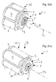
- the representations in the Fig. 20a / 21 a and 20b / 21 b correspond to the representations in the FIGS. 15 and 16 and show rotary actuators 1 with different power values alone due to their different lengths, ie concretely due to the different winding lengths for the respective electric motors 11 used.
- the Fig. 22 shows in isolation in perspective an example of a housing shell 2, which is not simply cylindrical, as in the embodiment of the Fig. 1 but consists of a plurality of individual cylinders, which are connected to each other and do not define a common interior for all electric motors 11 together, but for each electric motor 11 provide a separate receiving space, so that the electric motors would not require own individual housing.
- individual sub-cylinders could be used, which merge into one another and form a common interior space for all electric motors 11.
- Each of these two housing configurations can in the embodiments according to the Fig. 15 . 18 . 19 . 20a and 21 a be used.
- the rotary drive 1 is preferably designed so that only the length of the electric motors 11 or more precisely their windings is changed in a series or from a kit. Due to the different lengths of winding lengths in electric motors 11 different rotary actuators 1 different achievements can be realized solely by otherwise identical types. These windings are not shown separately in the figures of the drawing, as they are known to those skilled in the art without further and clear.
- the rotary actuators 1 are shown in the figures with output shafts as ISO flange, this is not limiting. Of course, for example, a Wellenstumpel with keyway or teeth etc. possible. Also, the shaft can be designed as a hollow shaft. Furthermore, it is advantageous to store the output shaft stiff.
- the rotary drive 1 can be realized both with an air cooling, as well as with a water cooling.
- a separate position measuring system can be combined with the rotary drive or integrated into it and thus a position determination and position adjustment can be realized.
- the position determination can be carried out on the rotary drive downstream mechanical components, on the output gear or on the output shaft of the rotary drive or on one or more of the combined motors and optionally serve via a motor control of the above already some example, or preferred embodiments have been used for position adjustment.
- the main innovation of the rotary drive 1 is that it is an electric motor drive 16 which contains a plurality of single common electric motors 11 to form a unitary compact electromotive drive 16 in a unit B, in particular in a common housing 4 or housing composite.
- the rotary drive 1 according to the invention can be provided as a modular system, which enables particularly economical realizations.
- this modular system there are in a simple manner different sizes and variants of the rotary drive 1.
- Variants such as different designs for the output shaft or other components of the output devices A are offered in the modular system as standard solutions. For particularly shorter designs or special mounting requirements there is also the possibility of using a hollow shaft.
Abstract
Die Erfindung betrifft einen Drehantrieb (1) mit einem elektromotorischen Antrieb (16), der auf Abtriebseinrichtungen (A) wirkt, an denen eine Antriebswirkung des elektromotorischen Antriebs (16) abnehmbar ist, wobei der elektromotorische Antrieb (16) eine Mehrzahl von Elektromotoren (11) enthält, die zu einer Baueinheit zusammengefasst sind, und dass alle Elektromotoren (11) der Mehrzahl von Elektromotoren (11) gemeinschaftlich an den Abtriebseinrichtungen (A) angreifen, die den Elektromotoren (11) nachgeschaltet sind. Ferner betrifft die Erfindung einen Bausatz zum Zusammenstellen eines Drehanatriebs (1) nach einem der vorhergehenden Ansprüche, wobei für unterschiedliche Leistungen des elektromotorischen Antriebs (16) Elektromotoren (11) gleichen Durchmessers und unterschiedlicher Wicklungslängen enthalten sind, und/oder wobei eine Mehrzahl von kombinierbaren Bestandteilen der Abtriebseinrichtungen (A) für unterschiedliche Montagen des Drehantriebs (1) und/oder für unterschiedliche Anschlüsse oder Kombinationen von Drehantriebsabnehmern, und/oder als Bestandteile eines Getriebes (17) zur Realisierung verschiedener Über- oder Untersetzungen des Drehantriebs (1) enthalten sind. Schließlich betrifft die Erfindung noch einen Zahnstangenantrieb (32; 34) mit einem Drehantrieb (1), wobei die Abtriebseinrichtungen (A) am von den Elektromotoren (11) abgewandten Ende ein Stirnrad (33; 35) aufweisen, das mit einer Zahnstange (36) kämmt.The invention relates to a rotary drive (1) having an electromotive drive (16) which acts on output devices (A) on which a drive effect of the electromotive drive (16) is removable, wherein the electromotive drive (16) comprises a plurality of electric motors (11 ), which are combined to form a structural unit, and that all the electric motors (11) of the plurality of electric motors (11) jointly act on the output devices (A), which are connected downstream of the electric motors (11). Furthermore, the invention relates to a kit for assembling a Drehanatriebs (1) according to one of the preceding claims, wherein for different powers of the electric motor drive (16) electric motors (11) of the same diameter and different winding lengths are included, and / or wherein a plurality of combinable components the output devices (A) for different assemblies of the rotary drive (1) and / or for different connections or combinations of rotary drive pickups, and / or as components of a transmission (17) for realizing various over or under ratios of the rotary drive (1) are included. Finally, the invention also relates to a rack drive (32, 34) with a rotary drive (1), wherein the output devices (A) at the end facing away from the electric motors (11) end a spur gear (33, 35) which with a rack (36) combs.
Description
Die vorliegende Erfindung betrifft einen Drehantrieb nach dem Oberbegriff des Anspruches 1 und ein Herstellungsverfahren dafür.The present invention relates to a rotary drive according to the preamble of
Beispielsweise aus der
Die vorliegende Erfindung hat und erreicht das Ziel, einen einfachen und wirtschaftlichen Drehantrieb bereitzustellen.The present invention has and aims to provide a simple and economical rotary drive.
Dazu schafft die Erfindung einen Drehantrieb nach Anspruhc 1. Ein solcher Drehantrieb enthält einen elektromotorischen Antrieb, der auf Abtriebseinrichtungen wirkt, an denen eine Antriebswirkung des elektromotorischen Antriebs abnehmbar ist, wobei der elektromotorische Antrieb eine Mehrzahl von Elektromotoren enthält, die zu einer Baueinheit zusammengefasst sind, und wobei alle Elektromotoren der Mehrzahl von Elektromotoren gemeinschaftlich an den Abtriebseinrichtungen angreifen, die den Elektromotoren nachgeschaltet sind.The invention provides a rotary drive according to
Bevorzugt enthält die Mehrzahl von Elektromotoren vier Elektromotoren und/oder beaufschlagen die Elektromotoren der Mehrzahl von Elektromotoren im Betrieb die Abtriebseinrichtungen gemeinschaftlich.Preferably, the plurality of electric motors contains four electric motors and / or act on the electric motors of the plurality of electric motors in operation, the output devices jointly.
Vorzugsweise ist ferner vorgesehen, dass der elektromotorische Antrieb eine Mehrzahl von baugleichen Elektromotoren und/oder asynchronen Elektromotoren enthält.Preferably, it is further provided that the electromotive drive includes a plurality of identical electric motors and / or asynchronous electric motors.
Weiterhin kann mit Vorzug vorgesehen sein, dass die Elektromotoren der Mehrzahl von Elektromotoren mit parallelen Ausgangswellen um eine Zentralachse verteilt angeordnet sind, und dass die Ausgangswelle eines jeden Elektromotors mit einem von letzterem angetriebenen Ritzel versehen ist, die Bestandteil der Abtriebseinrichtungen sind, und die Ritzel aller Elektromotoren mit einem gemeinsamen Abtriebszahnkranz der Abtriebseinrichtungen kämmen. Dabei ist es ferner bevorzugt, wenn die Mehrzahl von Elektromotoren gleichmäßig verteilt und/oder gleichmäßig beabstandet und/oder längs einer Kreislinie konzentrisch um die Zentralachse angeordnet sind. In Weiterbildung davon kann mit Vorteil vorgesehen sein, die Ritzel und der Abtriebszahnkranz der Abtriebseinrichtungen ein Getriebe mit vorgebbarer Über- oder Untersetzung bilden. Eine andere vorteilhafte Weiterbildung besteht darin, dass der gemeinsame Abtriebszahnkranz aller Elektromotoren über ein Kugellager gelagert ist.Furthermore, it can be provided with preference that the electric motors of the plurality of electric motors with parallel output shafts are distributed around a central axis, and that the output shaft of each electric motor is provided with a pinion driven by the latter, which are part of the output devices, and the pinions of all electric motors mesh with a common output sprocket of the output devices. It is further preferred if the plurality of electric motors evenly distributed and / or evenly spaced and / or are arranged along a circular line concentric about the central axis. In a further development of this, it can be advantageously provided that the pinions and the driven sprocket of the output devices form a gearbox with predeterminable transmission or reduction. Another advantageous development is that the common output ring gear of all electric motors is mounted on a ball bearing.
Ferner kann mit Vorzug vorgesehen sein, dass eine Steuerung zum Steuern der Gesamtheit der Elektromotoren enthalten ist. In Weiterbildung davon kann für die Gesamtheit der Elektromotoren (11) ein gemeinsamer Frequenzumrichter enthalten sein, der von der Steuerung angesteuert wird. Alternativ gibt es eine für spezielle Anwendungen oder Bauarten bevorzugte Ausgestaltung, gemäß der für die Gesamtheit der Elektromotoren zwei Frequenzumrichter enthalten sind, die von der Steuerung unterschiedlich angesteuert werden, um eine Spielfreiheit des Drehantriebs zu gewährleisten. Noch eine vorteilhafte Weiterbildung besteht darin, dass wenigstens ein Positions-, Winkel- oder Lagesensor enthalten ist, der mit der Steuerung zur Ist-Wert-Übertragung gekoppelt ist, und dass die Steuerung ausgelegt ist, die Elektromotoren in Abhängigkeit von wenigstens einem Ist-Wert und wenigstens einem festlegbaren oder festgelegten Soll-Wert zu steuern, um den Drehantrieb auf den Soll-Wert einzustellen. Ferner kann mit Vorteil zusätzlich oder alternativ vorgesehen sein, dass die Steuerung ausgelegt ist, so auf die einzelnen Elektromotoren einzuwirken, dass die einzelnen Elektromotoren gleichmäßig belastet werden, und/oder dass das Gesamtdrehmoment des elektromotorischen Antriebs auf alle Elektromotoren synchron verteilt wird.Further, it may be preferable that a controller for controlling the entirety of the electric motors is included. In a further development thereof, a common frequency converter, which is controlled by the controller, can be contained for the entirety of the electric motors (11). Alternatively, there is a preferred embodiment for specific applications or designs, according to which for the totality of the electric motors two frequency inverters are included, which are controlled differently by the controller in order to ensure a backlash of the rotary drive. Yet another advantageous development is that at least one position, angle or position sensor is included, which is coupled to the controller for actual value transmission, and that the controller is designed, the electric motors in dependence on at least one actual value and at least one set or set target value to set the rotary drive to the target value. Furthermore, it can advantageously be additionally or alternatively provided that the control is designed to act on the individual electric motors that the individual electric motors are uniformly loaded, and / or that the total torque of the electric motor drive is distributed synchronously to all electric motors.
Das Ziel der vorliegenden Erfindung wird auch durch einen Bausatz zum Zusammenstellen eines Drehanatriebs gemäß den vorstehenden Gestaltungen erreicht, wobei für unterschiedliche Leistungen des elektromotorischen Antriebs Elektromotoren gleichen Durchmessers und unterschiedlicher Wicklungslängen enthalten sind, und/oder wobei eine Mehrzahl von kombinierbaren Bestandteilen der Abtriebseinrichtungen für unterschiedliche Montagen des Drehantriebs und/oder für unterschiedliche Anschlüsse oder Kombinationen von Drehantriebsabnehmern, und/oder als Bestandteile eines Getriebes zur Realisierung verschiedener Über- oder Untersetzungen des Drehantriebs enthalten sind.The object of the present invention is also achieved by a kit for assembling a Drehanatriebs according to the above designs, wherein for different powers of the electric motor drive electric motors of the same diameter and different winding lengths are included, and / or wherein a plurality of combinable components of the output devices for different assemblies the rotary drive and / or for different connections or combinations of rotary drive pickups, and / or as components of a transmission for the realization of various over- or reductions of the rotary drive are included.
Ferner wird das Ziel der vorliegenden Erfindung auch mit einem Zahnstangenantrieb mit einem Drehantrieb gemäß den vorstehenden Gestaltungen erreicht, wobei die Abtriebseinrichtungen am von den Elektromotoren abgewandten Ende ein Stirnrad aufweisen, das mit einer Zahnstange kämmt.Further, the object of the present invention is also achieved with a rack drive with a rotary drive according to the above designs, wherein the output devices at the end remote from the electric motors have a spur gear which meshes with a rack.
Weitere bevorzugte und vorteilhafte Weiterbildungen der Erfindung ergeben sich aus den jeweils abhängigen Ansprüchen und deren Kombinationen sowie aus der nachfolgenden Beschreibung einzelner Ausführungsbeispiele der Erfindung.Further preferred and advantageous developments of the invention will become apparent from the respective dependent claims and their combinations as well as from the following description of individual embodiments of the invention.
Die Erfindung wird anhand von Ausführungsbeispielen nachfolgend unter Bezugnahme auf die Zeichnung lediglich exemplarisch näher erläutert, in der
- Fig. 1
- in einer schematischen perspektivischen Ansicht den Grundaufbau ein erstes Ausführungsbeispiel des Drehantriebs veranschaulicht,
- Fig. 2
- in einer schematischen perspektivischen Ansicht Einzelheiten des Grundaufbaus eines zweiten Ausführungsbeispiels des Drehantriebs veranschaulicht,
- Fig. 3
- in einer schematischen Draufsicht ein erstes Funktionsprinzip des zweiten Ausführungsbeispiels des Drehantriebs für einen linksdrehenden Antrieb veranschaulicht,
- Fig. 4
- in einer schematischen Draufsicht ein erstes Funktionsprinzip des zweiten Ausführungsbeispiels des Drehantriebs für einen rechtsdrehenden Antrieb veranschaulicht,
- Fig. 5
- in einer schematischen Draufsicht ein erstes Funktionsprinzip des zweiten Ausführungsbeispiels des Drehantriebs für einen spielfreien Antrieb veranschaulicht,
- Fig. 6
- in einer schematischen perspektivischen Ansicht Einzelheiten des Grundaufbaus eines dritten Ausführungsbeispiels eines Drehantriebs veranschaulicht,
- Fig. 7
- in einer schematischen perspektivischen Schnittansicht Einzelheiten des Grundaufbaus eines vierten Ausführungsbeispiels eines Drehantriebs veranschaulicht,
- Fig. 8
- in einer schematischen Schnittansicht die Einzelheiten des Grundaufbaus des vierten Ausführungsbeispiels eines Drehantriebs gemäß der
Fig. 7 veranschaulicht, - Fig. 9
- in einer schematischen perspektivischen teilweisen Schnittansicht weitere Einzelheiten des Grundaufbaus des vierten Ausführungsbeispiels eines Drehantriebs gemäß den
Fig. 7 und8 veranschaulicht, - Fig. 10
- in einer schematischen perspektivischen teilweisen Schnittansicht noch weitere Einzelheiten des Grundaufbaus des vierten Ausführungsbeispiels eines Drehantriebs gemäß den
Fig. 7 bis 9 veranschaulicht, - Fig. 11
- in einer schematischen perspektivischen Schnittansicht Einzelheiten des Grundaufbaus eines fünften Ausführungsbeispiels eines Drehantriebs veranschaulicht,
- Fig. 12
- in einer schematischen Draufsicht Einzelheiten des Grundaufbaus eines sechsten Ausführungsbeispiels eines Drehantriebs veranschaulicht,
- Fig. 13
- in einer schematischen perspektivischen Ansicht Einzelheiten des Grundaufbaus eines siebten Ausführungsbeispiels eines Drehantriebs veranschaulicht,
- Fig. 14
- in einer schematischen perspektivischen Ansicht Einzelheiten des Grundaufbaus eines achten Ausführungsbeispiels eines Drehantriebs veranschaulicht,
- Fig. 15
- in einer schematischen perspektivischen Ansicht Einzelheiten des Grundaufbaus eines achten Ausführungsbeispiels eines Drehantriebs veranschaulicht,
- Fig. 16
- in einer schematischen perspektivischen Ansicht Einzelheiten des Grundaufbaus des Ausführungsbeispiels des Drehantriebs aus der
Fig. 15 mit weggelassenem Gehäuse veranschaulicht, - Fig. 17
- in einer schematischen perspektivischen Ansicht Einzelheiten des Grundaufbaus des Ausführungsbeispiels des Drehantriebs aus der
Fig. 15 mit weggelassenem Gehäuse und einer Abwandlung bei Abtriebseinrichtungen veranschaulicht, - Fig. 18
- ein erstes Ausführungsbeispiel eines Zahnstangenantriebs mit einem Drehantrieb nach der Erfindung in einer schematischen perspektivischen Ansicht zeigt,
- Fig. 19
- ein zweites Ausführungsbeispiel eines Zahnstangenantriebs mit einem Drehantrieb nach der Erfindung in einer schematischen perspektivischen Ansicht zeigt,
- Fig. 20a/b
- in einer schematischen perspektivischen Ansicht Einzelheiten des Grundaufbaus eines weiteren Ausführungsbeispiels eines Drehantriebs mit und ohne Gehäuse veranschaulicht,
- Fig. 21a/b
- in einer schematischen perspektivischen Ansicht Einzelheiten des Grundaufbaus noch eines weiteren Ausführungsbeispiels eines Drehantriebs mit und ohne Gehäuse veranschaulicht, um Leistungsunterschiede zu dem Ausführungsbeispiel gemäß den
Fig. 21a /b zu veranschaulichen, und - Fig. 22
- in Alleinstellung perspektivisch ein Beispiel eines Gehäusemantels eines weiteren Ausführungsbeispiels des Drehantriebs zeigt.
- Fig. 1
- in a schematic perspective view of the basic structure illustrates a first embodiment of the rotary drive,
- Fig. 2
- in a schematic perspective view illustrates details of the basic structure of a second embodiment of the rotary drive,
- Fig. 3
- illustrated in a schematic plan view of a first operating principle of the second embodiment of the rotary drive for a left-handed drive,
- Fig. 4
- in a schematic plan view illustrates a first operating principle of the second embodiment of the rotary drive for a clockwise drive,
- Fig. 5
- illustrated in a schematic plan view of a first operating principle of the second embodiment of the rotary drive for a backlash-free drive,
- Fig. 6
- shows in a schematic perspective view details of the basic structure of a third embodiment of a rotary drive,
- Fig. 7
- in a schematic perspective sectional view illustrates details of the basic structure of a fourth embodiment of a rotary drive,
- Fig. 8
- in a schematic sectional view of the details of the basic structure of the fourth embodiment of a rotary drive according to the
Fig. 7 illustrates - Fig. 9
- in a schematic perspective partial sectional view of further details of the basic structure of the fourth embodiment of a rotary drive according to the
Fig. 7 and8th illustrates - Fig. 10
- in a schematic perspective partial sectional view of further details of the basic structure of the fourth embodiment of a rotary drive according to the
Fig. 7 to 9 illustrates - Fig. 11
- in a schematic perspective sectional view illustrates details of the basic structure of a fifth embodiment of a rotary drive,
- Fig. 12
- in a schematic plan view illustrates details of the basic structure of a sixth embodiment of a rotary drive,
- Fig. 13
- in a schematic perspective view illustrates details of the basic structure of a seventh embodiment of a rotary drive,
- Fig. 14
- in a schematic perspective view of details of the basic structure of an eighth embodiment of a rotary drive illustrates
- Fig. 15
- in a schematic perspective view of details of the basic structure of an eighth embodiment of a rotary drive illustrates
- Fig. 16
- in a schematic perspective view of details of the basic structure of the embodiment of the rotary drive from the
Fig. 15 illustrated with omitted housing, - Fig. 17
- in a schematic perspective view of details of the basic structure of the embodiment of the rotary drive from the
Fig. 15 illustrated with omitted housing and a modification in output devices, - Fig. 18
- shows a first embodiment of a rack drive with a rotary drive according to the invention in a schematic perspective view,
- Fig. 19
- shows a second embodiment of a rack drive with a rotary drive according to the invention in a schematic perspective view,
- Fig. 20a / b
- illustrated in a schematic perspective view of details of the basic structure of a further embodiment of a rotary drive with and without housing,
- Fig. 21a / b
- Illustrated in a schematic perspective view of details of the basic structure of yet another embodiment of a rotary drive with and without housing to performance differences from the embodiment according to the
Fig. 21a / b to illustrate, and - Fig. 22
- in perspective, an example of a housing shell of another embodiment of the rotary drive shows in perspective.
Anhand der nachfolgend beschriebenen und in den Zeichnungen dargestellten Ausführungs- und Anwendungsbeispiele wird die Erfindung lediglich exemplarisch näher erläutert, d.h. sie ist nicht auf diese Ausführungs- und Anwendungsbeispiele beschränkt. Verfahrens- und Vorrichtungsmerkmale ergeben sich jeweils analog auch aus Vorrichtungs- bzw. Verfahrensbeschreibungen.With reference to the embodiments and examples of application described below and illustrated in the drawings, the invention will be explained only by way of example, that is, it is not limited to these embodiments and applications. Process and device features result analogously also from device or process descriptions.
Einzelne Merkmale, die im Zusammenhang mit einem konkreten Ausführungsbeispiel angeben und/oder dargestellt sind, sind nicht auf dieses Ausführungsbeispiel oder die Kombination mit den übrigen Merkmalen dieses Ausführungsbeispiels beschränkt, sondern können im Rahmen des technisch Möglichen, mit jeglichen anderen Varianten, auch wenn sie in den vorliegenden Unterlagen nicht gesondert behandelt sind, kombiniert werden.Individual features that are indicated and / or illustrated in connection with a specific embodiment, are not limited to this embodiment or the combination with the other features of this embodiment, but may in the context of the technically possible, with any other variants, even if they are in are not treated separately.
Gleiche Bezugszeichen in den einzelnen Figuren und Abbildungen der Zeichnung bezeichnen gleiche oder ähnliche oder gleich oder ähnlich wirkende Komponenten. Anhand der Darstellungen in der Zeichnung werden auch solche Merkmale deutlich, die nicht mit Bezugszeichen versehen sind, unabhängig davon, ob solche Merkmale nachfolgend beschrieben sind oder nicht. Andererseits sind auch Merkmale, die in der vorliegenden Beschreibung enthalten, aber nicht in der Zeichnung sichtbar oder dargestellt sind, ohne weiteres für einen Fachmann verständlich.The same reference numerals in the individual figures and illustrations of the drawing designate the same or similar or the same or similar components. On the basis of the representations in the drawing, those features are also clear, which are not provided with reference numerals, regardless of whether such features are described below or not. On the other hand, features that are included in the present description but are not visible or illustrated in the drawing will be readily understood by those skilled in the art.
In den
Der Drehantrieb 1 enthält, wie der
Entgegengesetzt zum Unterteil 3 ist am anderen axialen Ende des Mantels oder Gehäusemantels 4, der auch als Gehäusemittelteil bezeichnet werden kann, ein Haltering 5 angeordnet, an dem eine Mehrzahl von Elektromotoren (in der
Auf der vom Mantel abgewandten Seite des Halterings 5 ist, wie bei dem ersten Ausführungsbeispiel in der
Ferner ist der Drehantrieb 1 gemäß dem ersten Ausführungsbeispiel mit einer Hohlwelle 8 gestaltet, so dass er als Hohlwellenantrieb eingesetzt werden kann. Allgemein wird die Hohlwelle 8 durch einen Innenzylinder 9 gebildet, der entweder bezüglich einer Drehbewegung von Abtriebszahnkranz (in der
Die Hohlwelle 8 ist, wie in der
In dem Gehäuse 4 sind weitere Komponenten untergebracht, die im Zusammenhang mit einem zweiten Ausführungsbeispiel des Drehantriebs 1 unter Bezugnahme auf die
Der Drehantrieb 1 des zweiten Ausführungsbeispiels gemäß der
Die Einheit aus der Mehrzahl von Elektromotoren 11, wie z.B. gemäß der
Wie durch die einheitliche Darstellung der einzelnen Elektromotoren 11 in der
Für die Anzahl und Anordnung der Elektromotoren 11 gilt allgemein, dass die Elektromotoren 11 eines elektromotorischen Antriebs 16 bevorzugt gleichmäßig verteilt um die Zentralachse 13 angeordnet sind. Alternativ oder zusätzlich kann auch als allgemeine Regel realisiert sein, dass die Elektromotoren 11 eines elektromotorischen Antriebs 16 vorzugsweise gleichmäßig beabstandet und/oder längs einer Kreislinie konzentrisch um die Zentralachse 13 angeordnet sind, d.h., dass die Ausgangswellen 12 aller Elektromotoren 11 auf einer gemeinsamen Kreislinie liegen. Sollten beispielsweise für bestimmte Leistungskurven des elektromotorischen Antriebs 16 unterschiedliche Elektromotoren mit unterschiedlichen individuellen Elektromotordurchmessern zusammengefasst werden, so würden sie nicht in identischen Abständen und nicht alle auf einer gemeinsamen um die Zentralachse 13 konzentrischen Kreislinie angeordnet sein, damit ihre Ritzel 14 mit dem gemeinsamen Abtriebszahnkranz 15 kämmen können.For the number and arrangement of the
Damit sind in dem Drehantrieb 1 der elektromotorische Antrieb 16 mit der Mehrzahl von Elektromotoren 11 und ein Getriebe 17 aus den Ritzeln 14 und dem Abtriebszahnkranz 15 zu einer kompakten Einheit insbesondere mit dem Gehäuse 4 zusammengefasst. Durch diese kombinierte Bauart von Getriebe 17 und elektromotorischem Antrieb 16 mit den Elektromotoren 11 baut die Antriebseinheit in Form des Drehantriebs 1 in vorteilhafter Weise besonders kompakt und kann eine optimal kurze und/oder schlanke Bauform erreicht werden.Thus, in the
In dem Drehantrieb 1 sind somit mehrere einzelne Elektromotoren 11 verbaut. Diese übertragen ihre Leistung jeweils über ein Zahnrad in Form des Ritzels 14 am Abtrieb, d.h. an der Ausgangswelle 12 auf den gemeinsamen Abtriebszahnkranz 15 des Drehantriebs 1. Der gemeinsame Abtriebszahnkranz 15 kann innen- oder außenverzahnt sein und ist dann entsprechend außerhalb bzw. innerhalb der Ritzel 14 angeordnet. Die Leistungen der einzelnen Elektromotoren 11 werden somit zu einer gemeinsamen Ausgangsleistung zusammengefasst.In the
Der Vollständigkeit halber wird noch darauf hingewiesen, dass bei dem Drehantrieb 1 des zweiten Ausführungsbeispiels in der
In den
Wie in den
Die
Durch den Einsatz mehrerer Elektromotoren 11 kann ohne weitere mechanische Maßnahmen und Mittel ein Verspannen des Drehantriebs 1, d.h. der Ritzel 14 gegenüber dem Abtriebszahnkranz 15 und somit ein Verspannen innerhalb der Antriebseinrichtugen A oder bei entsprechender Bauart des Getriebes 17 selbst, ermöglicht werden. Dazu werden einzelne der Elektromotoren 11 gleichzeitig in entgegengesetzte Drehrichtungen betrieben, wie die um die Ritzel 14 herum gebogenen Pfeile 18 und 19 verdeutlichen, was durch entgegengesetzte Polung einzelner Elektromotoren 11 gesteuert und erreicht werden kann. Bei n Elektromotoren kann die Spielfreiheit mit dieser Technik bereits durch einen bezüglich allen anderen n-1 Elektromotoren gegenläufig betriebenen Elektromotor erreicht werden. Dies ermöglicht einen spielfreien Drehantrieb 1 und damit eine spielfreie Positionierung der Ausgangsseite, d.h. von Abtriebszahnkranz 15 und ggf. Anschlussplatte 6. Aufgrund dieser Möglichkeit können Zahnräder als Ritzel 14 und als Abtriebszahnkranz 15 mit niedriger Qualität und insbesondere größeren Maßtoleranzen eingesetzt werden, was den Drehantrieb 1 kostengünstiger macht. Eine entsprechende Steuerung ist optional, d.h. dass der erfindungsgemäße Drehantrieb 1 grundsätzlich auch ohne eine derart realisierte Spielfreiheit von Vorteil ist.By using a plurality of
In der
Beim dritten Ausführungsbeispiel gemäß der
Durch Variation der Anzahl der Antriebs- oder Elektromotoren 11 kann in einem großen Leistungsbereich die gewünschte Leistung erreicht werden. Vorteilhafterweise wird angestrebt, dass in einer gleichen Baureihe immer die gleichen Elektromotoren 11 zum Einsatz kommen und so aufgrund der Herstellung einer gesteigerten Stückzahl die Elektromotoren 11 kostengünstigst bereitgestellt werden können. Aber auch unterschiedliche Bau-/Wicklungslängen der Elektromotoren 11 ermöglichen die Bedienung eines großen Leistungsbereichs auf einfach und kostengünstige Weise.By varying the number of drive or
Wie schon im Zusammenhang mit dem ersten Ausführungsbeispiel gemäß der
Die
Der Drehantrieb 1 gemäß dem vierten Ausführungsbeispiel enthält als Baueinheit B das Gehäuse 4 mit dem zylindrischen Mantel 2 und dem ringförmigen Unterteil 3 sowie der Anschlussplatte 6, mit der integral der Innenzylinder 9 für die Hohlwelle 8 ausgebildet ist. Die Anschlussplatte 6 ist mit Montagebohrungen 7 zur Befestigung eines anzutreibenden Teils (nicht dargestellt) versehen und ist Bestandteil der Antriebseinrichtungen A.The
Im Inneren des Gehäuses 4 und damit der Baueinheit B sind die Elektromotoren 11 kreisartig mit jeweils zueinander parallelen Ausgangswellen 12 zwischen dem Mantel 2 und dem Innenzylinder 9 angeordnet. Die Ausgangswellen 12 der Elektromotoren 11 gehen durch entsprechende Öffnungen (nicht bezeichnet) in dem Haltering 5 hindurch, an dem die Elektromotoren 11 direkt oder indirekt geeignet befestigt sind, und tragen an ihren freien, von den Elektromotoren 11 abgewandten Enden jeweils ein Ritzel 14. Dadurch wird für die Ausgangswellen 12 sowie für den gesamten Drehantrieb 1 eine steife und stabile Lagerung erreicht, so das zur Abstützung solchermaßen aufgebauten Systeme keine zusätzliche Lagerung erforderlich ist.Inside the
Nachfolgend wird auf den weiteren konstruktiven Aufbau des Drehantriebs 1 eingegangen. Die Ritzel 14 an den Enden der Ausgangswellen 12 sind in dem Haltering 5 sozusagen "versenkt". Zwischen den Ritzeln 14 und dem Haltering 5 ist der im vorliegenden Fall innenverzahnte Abtriebszahnkranz 15 untergebracht, der ebenfalls nicht über die axiale Ausdehnung des Halterings 5 vorsteht, mit seiner Innenverzahnung mit allen Ritzeln 14 kämmt und am bezüglich der beim Betrieb der Elektromotoren 11 entstehenden Drehbewegung des Abtriebszahnkranzes 15 feststehenden Haltering 5 mittels eines Kugellagers 21 mit Kugeln 22 gelagert ist. An den Haltering 5 schließt sich in Axialrichtung (definiert in allen Figuren der vorliegenden Unterlagen durch den zylindrischen Mantel 2 des Gehäuses 4 sowie den Innenzylinder 9 der Hohlwelle 8 oder einfach durch die Zentralachse 13) die Abschlussplatte 6 an, die, damit sie sich mit dem Abtriebszahnkranz 15 mitdreht, wenn dieser über die Ausgangswellen 12 und Ritzel 14 der Elektromotoren 11 drehangetrieben wird, fest mit dem Abtriebszahnkranz 15 verbunden ist, so dass die Ausgangswellen 12 und Ritzel 14 der Elektromotoren 11 und die Abschlussplatte 6 (bie diesem Ausführungsbeispiel samt Innenzylinder 9) insgesamt die Abtriebseinrichtungen A bilden. Durch die integrale Bauweise von Abschlussplatte 6 und Innenzylinder 9 liegt beim Betrieb des Drehantriebs 1 eine sich entsprechend drehende Hohlwelle 8 vor.Subsequently, the further structural design of the
Die
Die
In vergleichbarer Darstellung zur
Ferner sind, wie der Vergleich der Abbildungen der
Für sowohl das vierte Ausführungsbeispiel gemäß den
Insbesondere bei einem innenverzahnten Abtriebszahnkranz 15 gemäß dem in den
Wie schon erwähnt wurde, hier aber nochmals betont wird, können der Abtriebszahnkranz 15 und die Anschlussplatte 6 als Bestandteil der Abtriebseinrichtungen A integral ausgebildet sein oder kann der Abtriebszahnkranz 15 direkt eine Ausgestaltung haben, so dass er die Funktion und Wirkung der Anschlussplatte 6 gleich mit erfüllt.As already mentioned, but here again emphasized, the driven
Ferner sind auch Bauarten ohne Kugellager 21 oder 23 oder mit Lagerungen zwischen Abtriebszahnkranz 15 und Flansch 20 und/oder Mantel 2 des Gehäuses 4 möglich. Dabei kann auch vorgesehen werden, dass eine Abstützung des Abtriebszahnkranzes 15 über ein Lager durch entsprechende Führung und Festlegung des Abtriebszahnkranzes 15 nicht erforderlich ist. Lager können insbesondere auch dann entfallen, wenn keine entsprechenden oder besonderen Kräfte von der Abtriebsseite her auf den Abtriebszahnkranz 15 wirken. Bei Bauarten mit Lagern sind diese nicht auf Ausführungen mit Kugellagern beschränkt, sondern können auch Gleitlager, Rollenlager oder Wälzlager eingesetzt werden. Auch diesbezüglich kann der Fachmann ohne selbst erfinderisch tätig werden zu müssen mit seinem Fachwissen ohne weiteres selbst die geeignete Technik auswählen und einsetzen.Furthermore, designs without
Aus Platzspargründen in Radialrichtung des Gehäuses 4 des Drehantriebs 1 kann ein Lager für den Abtriebszahnkranz 15 zwischen letzterem und dem Flansch 20 des Halterings 5 sowohl bei innen- als auch außenverzahnter Ausführung des Abtriebszahnkranzes 15 gewählt werden, wobei dann der Abtriebszahnkranz 15 in geeigneter Weise axial festgelegt wird.For space-saving reasons in the radial direction of the
Allgemein ist somit bei den entsprechenden Ausführungsbeispielen des Drehantriebs 1 bedarfsgemäß vorgesehen, dass der Drehantrieb 1 für den Abtriebszahnkranz 15 eine Lagerung beinhaltet, mit der bevorzugt alle Belastung, die aufgrund des aufgebauten Systems bestehend aus Drehantrieb 1 und damit angetriebenen Komponenten im Einsatzfall entstehen, aufgefangen werden können. Vorzugsweise wird angestrebt, dass die Lagerung möglichst steif ausgeführt wird. Lediglich als eine bevorzugte Ausgestaltung wird für eine steife Lagerung der Einsatz eines Vierpunktlagers bzw. eines Kreuzrollenlagers genannt.In general, therefore, the
Ein Verkippen der Lagerung aufgrund einer Momentenbelastung sollte so gering wie möglich gehalten werden. Vorteilhaft dafür ist es, wenn ein möglichst großer Lagerdurchmesser verwendet wird, was bauartbedingt für eine vom Abtriebszahnkranz 15 getrennte Lagerung am besten und einfachsten mit einem innenverzahnten Abtriebszahnkranz 15 erreicht wird. Dass dies im Zusammenhang mit dem feststehenden Lager- oder Lagerungsring in Form des Halterings 5 als Teil des Gehäuses 4 als besonders platzsparende Lagerlösung möglich ist, wurde bereits erläutert. Ebenso vorteilhaft im Hinblick auf eine platzsparende, kompakte Bauweise wirkt sich aus, wenn der bewegliche Lager- oder Lagerungsring direkt durch den Abtriebszahnkranz 15 als Komponente des Getriebes 17 gebildet ist, wobei entsprechende Vorteile sowohl mit innen- als auch außenverzahntem Abtriebszahnkranz 15 erreicht werden.A tilting of the bearing due to a moment load should be kept as low as possible. It is advantageous if the largest possible bearing diameter is used, which is achieved by design for a separate from the
Eine Lagerung wird, wie erläutert wurde, somit im Bereich des Getriebes 17 verbaut. Zusätzlich kann zur weiteren Absicherung bei Bedarf gegen ein Verkippen ein zweites Lager im Bereich des zum Getriebe 17 entgegengesetzten axialen Ende des Drehantriebs 1 beispielsweise zwischen Innenzylinder 9 der Hohlwelle 8 und dem Unterteil 3 angebracht werden, wenn der Innenzylinder 9 z.B. mit dem Abtriebszahnkranz 15 verbunden zu den Abtriebseinrichtungen gehört.As has been explained, storage is thus installed in the area of the
Vorzugsweise wird die Ausgangsseite des Drehantriebs 1, also die Elektromotoren 11 im Bereich vor den Ausgangswellen 12 oder ggf. der Mantel 2 des Gehäuses 4 vor dem Abtriebszahnkranz 5 oder der Anschlussplatte 6 sehr massiv extern befestigt oder gelagert, so dass keine weitere externe Lagerungen für die auf dem Drehantrieb 1 aufgebauten oder daran angeschlossenen Einheiten erforderlich sind.Preferably, the output side of the
Anhand der
Bei dem Drehantrieb 1 gemäß der vorliegenden Erfindungen können ferner beispielsweise ein Messsystem zur Lage- oder Positionsbestimmung (z.B. Drehwinkel der Abtriebseinrichtungen A oder der Ausgangswellen 12 der Elektromotoren 11) und/oder eine Abdichtung des Gehäuses 4 vorgesehen sein, um den Drehantrieb insbesondere für den Einsatz in der Lebensmittelindustrie geeignet zu machen. Im Präzessionsbereich werden mit Vorzug Befestigungen des Drehantriebs und/oder Lager in dem Getriebe 17 mit Vorspannung eingesetzt.In the
Das Gehäuse 4 ist bei jeglicher erfindungsgemäßer Bauart mit Vorteil im Hinblick auf seine Steifigkeit aufgrund seiner Wandstärker so dimensioniert, dass keine weitere zusätzliche externe Lagerung bzw. Lagerwelle für den Drehantrieb 1 erforderlich ist. Die Belastung des aufgebauten Systems aus Drehantrieb 1 und davon angetriebenen Komponenten kann direkt über den Drehantrieb 1 in die Grundstruktur des Montageortes des Drehantriebs 1 eingeleitet werden.The
Wie anhand der bisherigen Beschreibung deutlich wurde, liegt ein besonderer Vorteil des Drehantriebs 1 in der Verwendung einer Baueinheit B mit einer Mehrzahl von Elektromotoren 11, die gemeinschaftlich auf einen gemeinsamen Abtriebszahnkranz 15 oder allgemein Abtriebseinrichtungen A wirken. Damit kann vorteilhafterweise ein Baukastensystem realisiert werden. Die Gesamtleistung des Drehantriebs 1 wird durch die Einzelleistungen der Mehrzahl von Elektromotoren 11 und deren Anzahl festgelegt. Vorteilhafterweise kommen in einer Baureihe gleiche Motoren, insbesondere Asynchronmotoren, zum Einsatz, wodurch infolge der entsprechenden Stückzahl bei der Herstellung niedrigere Kosten für die einzelnen Elektromotoren 11 und damit den gesamten Drehantrieb 1 erreicht werden können.As was apparent from the previous description, a particular advantage of the
Erfindungsgemäße Drehantriebe 1 können beispielsweise und mit Vorteil als Zahnstangenantriebe (siehe später im Zusammenhang mit den
In Kombination mit einer Steuerung der Elektromotoren 11 für einen spielfreien Betrieb gemäß der Beschreibung zur
Vorstehend wurden als vorzugsweise Ausgestaltungen und im Rahmen von Ausführungsbeispielen Drehantriebe 1 mit einer Mehrzahl von baugleichen Elektromotoren 11 angegeben. Dies beinhaltet insbesondere explizit auch, dass ein erfindungsgemäßer Drehantrieb 1 auch eine Mehrzahl von Elektromotoren 11 enthalten kann, die nicht alle baugleich sind. Bei den in einem Drehantrieb 1 verbauten Elektromotoren 11 können auch Unterschiede in der Bauform, bei der Ausstattung bei den Leistungsdaten und/oder bei den Eigenschaften bestehen. Einer oder mehrere von den Elektromotoren 11 eines Drehantriebs 1 kann/können anders sein als ein oder mehrere der übrigen Elektromotoren 11 dieses Drehantriebs 1.Above were as preferred embodiments and in the context of embodiments of
So kann zum Beispiel ein Elektromotor 11 in einer oder in beiden Drehrichtung(en) mit einem zusätzlichen Drehgeber (nicht gezeigt) ausgestattet sein, der von einigen Motorherstellern als Resolver bezeichnet wird und mittels dem eine Rückmeldung zur Steuerung erhalten werden kann. Alternativ oder zusätzlich kann einer oder können mehrere der Elektromotoren 11 mit einem Temperaturüberwachungsschalter (nicht gezeigt) ausgestattet sein. Zusammengefasst kann/können somit einer oder mehrere der Elektromotoren 11 eines Drehantriebs 1 bezüglich dem oder den übrigen Elektromotor(en) 11 dieses Drehantriebs 1 verschieden sein, und zwar hinsichtlich Bauform, Ausstattung, Leistung und/oder sonstigen Eigenschaften. Die Gestaltung ist auch nicht auf die Verwendung von zwei unterschiedlichen Arten von Elektromotoren 11 bei einem Drehantrieb beschränkt.Thus, for example, an
Der Vollständigkeit halber wird auch noch darauf hingewiesen, dass bei den entsprechenden Ausführungsbeispielen der Halterring 5 mit dem zylindrischen Mantel 2 ein gemeinsames, insbesondere integrales Bauteil sein kann, und/oder dass der Mantel 2 mit dem Unterteil 3 ein gemeinsames, insbesondere integrales Bauteil sein kann. Außerdem kann das Gehäuse 4 auch anders als aus Mantel, Unterteil und Haltering aufgebaut sein. Der Mantel muss nicht zylindrisch sein und kann z.B. auch in Längs- und/oder Querrichtung geteilt seinFor the sake of completeness, it is also pointed out that in the corresponding exemplary embodiments, the retaining
Der erfindungsgemäße Drehantrieb 1 erfüllt auch den Bedarf an Direktantrieben, wie sie z.B. auch im Bereich der Zahnstangenantriebe immer häufiger eingesetzt werden. Dazu schafft der erfindungsgemäße Drehantrieb insbesondere eine kompakte Antriebs- oder Baueinheit B, die bei bevorzugten Ausgestaltungen nicht nur den elektromotorischer Antrieb 16 mit den Elektromotoren 11, sondern auch gleich noch die Getriebeeinheit 17 der Abtriebseinrichtungen A in der Baueinheit B kombiniert. Dabei ermöglicht der erfindungsgemäße Drehantrieb 11 insbesondere auch die kraftvolle und genaue Positionierung des Antriebes.The
Der neuartige erfindungsgemäße Drehantrieb 1 ermöglicht beispielsweise als Zahnstangenantrieb eine höchst kraftvolle genaue Positionierung. Im gemeinsamen Einsatz mit einem spielfreien Stirnrad oder einer Steuerung der Elektromotoren mittels Gegenläufigkeit zur Spielfreiheit besteht sogar die Möglichkeit, den kompletten Antriebsstrang durchgehend spielfrei zu halten. Natürlich kann der Antrieb aber auch mit einem gewöhnlichen Standard-Stirnrad betrieben werden.The novel
Bei bevorzugten Ausführungsformen
- sind im Inneren eines Gehäuses oder einer Gehäusekombination des Drehantriebs 1
mehrere Elektromotoren 11 verbaut; diese bündeln ihre Leistung auf gemeinsame Abtriebseinrichtungen A, wie z.B. eine gemeinsame Ausgangswelle, - wird die Leistung der einzelnen Elektromotoren 11 somit zu einer gemeinsamen Ausgangsleistung zusammengefasst,
- werden z.B. in
einem Drehantrieb 1 alsZahnstangenantrieb vier Elektromotoren 11 verbaut, - kann durch geeignete
Wahl von Ritzeln 14 und Abtriebszahnkranz 15, der innenverzahnt oder außenverzahnt, d.h. als Zahnrad gestaltet sein kann, eine geforderte Übersetzung/Untersetzung eines daraus gebildeten Getriebes 17 realisiert werden, das Bestandteil der gemeinsamen Abtriebseinrichtungen A desDrehantriebs 1 und vorzugsweise auch Bestandteil der Baueinheit B desDrehantriebs 1 ist, - kann zusätzlich das
mit dem Drehantrieb 1 erzielbare Drehmoment durch Auswahl unterschiedlicher Übersetzungen indem Getriebe 17 je nach Kundenwunsch angepasst werden, und/oder - wird die Motor- und Getriebeeinheit, d.h. der elektromotorische Antrieb 16
und das Getriebe 17, in einem gemeinsamen Gehäuse 4 oder einem Verbund von Einzelgehäusen zu einer Baueinheit B zusammengepackt; dies ermöglicht eine höchst kompakte platzsparende Bauform.
- are inside a housing or a housing combination of the
rotary drive 1 moreelectric motors 11 installed; These combine their power to common output devices A, such as a common output shaft, - the power of the individual
electric motors 11 is thus combined to a common output power, - For example, four
electric motors 11 are installed in arotary drive 1 as a rack drive, - can be realized by a suitable choice of
pinions 14 and drivenring gear 15, the internally toothed or externally toothed, ie designed as a gear, a required translation / reduction of agear 17 formed therefrom, the component of the common output devices A of therotary drive 1 and preferably also part of Assembly B of therotary drive 1 is, - In addition, the achievable with the
rotary drive 1 torque can be adjusted by selecting different ratios in thetransmission 17 depending on the customer, and / or - the motor and gear unit, ie the
electric motor drive 16 and thegear 17, are packed together in acommon housing 4 or a composite of individual housings to form a unit B; This allows a very compact space-saving design.
Mit besonderem Vorteil können bei weiteren bevorzugten Ausgestaltungen des erfindungsgemäßen Drehantriebs 1 geeignete Ansteuerungen der einzelnen Elektromotoren 11 realisiert werden. Durch offene Automatisierungsplattformen hat der Anwender die Möglichkeit, eigenes Maschinen-Know-How zu integrieren. CNC-Programme in DIN66025-Sprache (G- / M-Befehle) können z.B. in mehreren unabhängigen Kanälen ablaufen. Beispielsweise können SPS- / Motion Control- und Visualisierungsfunktionen mit CoDeSys V3 programmiert werden. So lassen sich z.B. über die Steuerung smmx auch Touch-Panel- und WEB-Visualisierungen realisieren.With particular advantage, suitable controls of the individual
Bei bevorzugten Ausführungsformen der Ansteuerungen kann vorgesehen sein:
- hinsichtlich der Auswahl der Steuerungskomponenten kann es sich um handelsübliche Frequenzumrichter handeln,
- hinsichtlich der Auswahl der Steuerungskomponenten kann es sich z.B. um die Standardsteuerung smmx von der Firma SM Motion Control http://www.smmotioncontrol.de/produkte/steuerungen/smmx handeln, eine frei programmierbare einfache Steuerung, die eine ständige Ist-Soll-Wert-Abfrage hinsichtlich der Winkellage/Drehlage von Motor(en) und/oder Wellen/Ritzeln/Zahnrädern durchführt und direkt beispielsweise einen Frequenzumrichter ansteuert, der dann die Motoren mit Strom beaufschlägt, falls der Drehwinkel korrigiert werden soll,
- passende Regler-Parameter können im Rahmen der Programmierung der Steuerung eingestellt werden, wobei vorzugsweise eine Steuerungsmaske vorgesehen ist, mit der der Anwender im Einrichtbetrieb des Drehantriebs 1 die Parameter verstellen kann; damit kann eine Art mathematische Beziehung zwischen einer Eingangsgröße (z.B. Winkelsensor am Antrieb) und einer Ausgangsgröße an der Steuerung (z.B. Ansteuerung eines Frequenzumrichters) beschrieben werden, und/oder die Regelparameter können vom Verhalten des Gesamtsystems (z.B. bewegte Masse, Massenträgheiten etc.) abhängig sein und/oder können je nach Kundenanwendung speziell angepasst werden,
- zwei Frequenzumrichter können unterschiedlich von der Steuerung angesteuert werden, um
den Drehantrieb 1 für eine Spielfreiheit ansteuern und einen entsprechenden RegelAlgorithmus durchführen zu können, den die Steuerung in einem solchen Fall realisiert, - die einzelnen Elektromotoren 11 werden gleichmäßig belastet,
- das Gesamtdrehmoment wird auf alle Elektromotoren 11 synchron verteilt, und/oder
alle Elektromotoren 11 haben zusammen einen gemeinsamen Frequenzumrichter.
- with regard to the selection of the control components may be commercially available frequency converter,
- With regard to the selection of the control components, it can be, for example, the smmx standard controller from SM Motion Control http://www.smmotioncontrol.de/produkte/steuerungen/smmx , a freely programmable simple controller that provides a constant actual setpoint value Query with respect to the angular position / rotational position of motor (s) and / or shafts / pinions / gears and directly, for example, drives a frequency converter, which then supplies power to the motors, if the rotation angle is to be corrected,
- suitable controller parameters can be set as part of the programming of the controller, wherein preferably a control mask is provided with which the user can adjust the parameters in Einrichtbetrieb the
rotary actuator 1; Thus, a kind of mathematical relationship between an input variable (eg angle sensor on the drive) and an output variable on the controller (eg control of a frequency converter) can be described, and / or the control parameters depending on the behavior of the overall system (eg moving mass, inertia, etc.) be and / or can be customized according to the customer's application, - two frequency inverters can be controlled differently by the control in order to control the
rotary drive 1 for a backlash and to be able to execute a corresponding control algorithm, which the control realizes in such a case, - the individual
electric motors 11 are loaded evenly, - the total torque is distributed synchronously to all
electric motors 11, and / or - all
electric motors 11 together have a common frequency converter.
Vorzugsweise handelt es sich bei den Elektromotoren 11 um asynchrone Elektromotoren oder Asynchronmotoren. Versuche haben ergeben, dass alle Motoren dann eine gleichmäßige Stromaufnahme haben und das System auf einfach und kostengünstige Weise funktioniert. Synchronmotoren, Servomotoren etc. würden zum Funktionieren aufwendigere Steuerungen erfordern.Preferably, the
Gemäß weiteren bevorzugten Ausführungsbeispielen wird an der Ausgangs- oder Abtriebswelle des elektromotorischen Antriebes 16, oder an einer anderen geeigneten Komponente der Abtriebseinrichtungen A mit einem handelsüblichen Winkelsensor die Position, d.h. die Winkel(ein)stellung gemessen. Die ist aber nicht zwingend notwendig, sondern es kann z.B. auch ein Linearmesssystem an einzelnen Verfahrachsen, welche ein Zahnstangenantrieb mit dem Drehantrieb antreibt, zur Positionserfassung für die Steuerung des Drehantriebs 1 als Ist-Wert-Erfassung eingesetzt werden. Ganz allgemein kann jegliche Realisierung einer Lagerregelung zum Einsatz kommen.According to further preferred embodiments, at the output or output shaft of the
In den
Die
In der
Die
Die Darstellungen in den
Die
Der Drehantrieb 1 wird vorzugsweise so konzipiert, dass in einer Baureihe oder aus einem Bausatz nur die Länge der Elektromotoren 11 oder genauer deren Wicklungen geändert wird. Durch die unterschiedlich langen Wicklungslängen bei Elektromotoren 11 verschiedener Drehantriebe 1 können alleinig dadurch bei ansonsten gleichen Bauarten verschiedene Leistungen realisiert werden. Diese Wicklungen sind in den Fig. der Zeichnung nicht gesondert dargestellt, da sie einem Fachmann ohne weitere bekannt und klar sind.The
Alle Teile an der Vorderseite des Drehantriebes 1, wo die Getriebeeinheit oder das Getriebe 17 unter Zusammenfassung der Elektromotoren 11 liegt, also gemäß de Ausführungsbeispielen der Haltering 5 sowie die Rückseite (Unterteil 3) (vergleiche
Soweit die Ausführungsbeispiele der Drehantriebe 1 in den Figuren mit Abgangswellen als ISO-Flansch dargestellt sind, ist dies nicht beschränkend. Natürlich ist beispielsweise auch ein Wellenstumpel mit Passfedernut oder Verzahnung etc. möglich. Auch kann die Welle als Hohlwelle ausgeführt werden. Ferner ist es von Vorteil, die Abtriebswelle steif zu lagern.As far as the embodiments of the
Der Drehantrieb 1 kann sowohl mit einer Luftkühlung, als auch mit einer Wasserkühlung realisiert werden.The
Ferner kann ein gesondertes Positionsmesssystem mit dem Drehantrieb kombiniert oder in diesen integriert werden und damit eine Positionsbestimmung und Positionseinstellung realisiert werden. Die Positionsbestimmung kann dabei an dem Drehantrieb nachgeschalteten Mechanikkomponenten, am Abtriebszahnrad oder an der Abtriebswelle des Drehantriebs oder an einem oder mehreren der zusammengefassten Motoren erfolgen und ggf. über eine Motorsteuerung, von der vorstehend bereits einige beispielsweise oder bevorzugte Ausgestaltungen erläutert wurden, zur Positionseinstellung dienen.Furthermore, a separate position measuring system can be combined with the rotary drive or integrated into it and thus a position determination and position adjustment can be realized. The position determination can be carried out on the rotary drive downstream mechanical components, on the output gear or on the output shaft of the rotary drive or on one or more of the combined motors and optionally serve via a motor control of the above already some example, or preferred embodiments have been used for position adjustment.
Generell gesprochen liegt die Hauptinovation des Drehantriebs 1 darin, das es sich um einen elektromotorischen Antrieb 16 handelt, der mehrere einzelne gemeinsam wirkende Elektromotoren 11 zur Bildung eines einheitlichen kompakten elektromotorischen Antriebs 16 in einer Baueinheit B insbesondere in einem gemeinsamen Gehäuse 4 oder Gehäuseverbund enthält.Generally speaking, the main innovation of the
Mit besonderem Vorteil kann der erfindungsgemäße Drehantrieb 1 als ein Baukastensystem bereitgestellt werden, was besonders wirtschaftliche Realisierungen ermöglicht. In diesem Baukastensystem gibt es auf einfache Weise unterschiedliche Größen und Varianten des Drehantriebs 1. Varianten wie zum Beispiel verschiedene Bauformen für die Abtriebswelle oder andere Komponenten der Abtriebseinrichtungen A werden im Baukastensystem als Standardlösungen angeboten. Für insbesondere kürzere Bauformen oder spezielle Anbringungserfordernisse besteht auch die Möglichkeit des Einsatzes einer Hohlwelle.With particular advantage, the
Die Erfindung ist anhand der Ausführungsbeispiele in der Beschreibung und in der Zeichnung lediglich exemplarisch dargestellt und nicht darauf beschränkt, sondern umfasst alle Variationen, Modifikationen, Substitutionen und Kombinationen, die der Fachmann den vorliegenden Unterlagen insbesondere im Rahmen der Ansprüche und der allgemeinen Darstellungen in der Einleitung dieser Beschreibung sowie der Beschreibung der Ausführungsbeispiele entnehmen und mit seinem fachmännischen Wissen sowie dem Stand der Technik kombinieren kann. Insbesondere sind alle einzelnen Merkmale und Ausgestaltungsmöglichkeiten der Erfindung kombinierbar.The invention is illustrated by way of example only and not by way of example in the description and the drawing, but includes all variations, modifications, substitutions and combinations that the skilled person the present documents in particular in the context of the claims and the general representations in the introduction This description and the description of the embodiments can be found and combined with his expert knowledge and the prior art. In particular, all individual features and design options of the invention can be combined.
Claims (15)
Applications Claiming Priority (2)
| Application Number | Priority Date | Filing Date | Title |
|---|---|---|---|
| DE202013005840 | 2013-07-01 | ||
| DE202014004481 | 2014-06-04 |
Publications (2)
| Publication Number | Publication Date |
|---|---|
| EP2822159A2 true EP2822159A2 (en) | 2015-01-07 |
| EP2822159A3 EP2822159A3 (en) | 2016-01-20 |
Family
ID=51062618
Family Applications (1)
| Application Number | Title | Priority Date | Filing Date |
|---|---|---|---|
| EP14002249.2A Withdrawn EP2822159A3 (en) | 2013-07-01 | 2014-07-01 | Rotary drive |
Country Status (1)
| Country | Link |
|---|---|
| EP (1) | EP2822159A3 (en) |
Cited By (3)
| Publication number | Priority date | Publication date | Assignee | Title |
|---|---|---|---|---|
| EP3104503A1 (en) | 2015-06-08 | 2016-12-14 | WMH Herion Antriebstechnik GmbH | Rotary drive with no play |
| WO2017167617A1 (en) * | 2016-03-30 | 2017-10-05 | Deregallera Holdings Ltd | In-wheel electric motor unit |
| EP4184764A4 (en) * | 2020-09-23 | 2024-01-24 | Samsung Electronics Co Ltd | Electronic apparatus including flexible display |
Citations (1)
| Publication number | Priority date | Publication date | Assignee | Title |
|---|---|---|---|---|
| DE102006046694A1 (en) | 2006-09-29 | 2008-04-03 | Siemens Ag | Drive system with hollow shaft motor and gearbox |
Family Cites Families (12)
| Publication number | Priority date | Publication date | Assignee | Title |
|---|---|---|---|---|
| US4691119A (en) * | 1985-06-20 | 1987-09-01 | Westinghouse Electric Corp. | Permanent magnet alternator power generation system |
| GB2235246A (en) * | 1989-06-20 | 1991-02-27 | Epic Prod Ltd | A drive system for a pump/compressor |
| JPH0946969A (en) * | 1995-08-02 | 1997-02-14 | Kichinosuke Nagashio | Electric motor unit |
| DE19714784A1 (en) * | 1997-04-10 | 1998-10-22 | Danfoss As | Compact drive |
| US6700272B1 (en) * | 1997-09-30 | 2004-03-02 | Emf 97 Elektro-Maschinen-Vertrieb-Magnettechnik- Und Forschungs Gmbh | Reluctance motor with gearless step-down without electronic control of rotating field |
| CN1623265A (en) * | 2002-01-30 | 2005-06-01 | 约翰尼斯·弗雷德里克·威塞尔斯 | Electric motor and vehicle powered thereby |
| US8232700B2 (en) * | 2008-12-19 | 2012-07-31 | Pratt & Whitney Canada Corp. | Multi-rotor electric machine |
| CA2773362A1 (en) * | 2009-08-14 | 2011-02-17 | Convergent Power, Inc. | Pulsed multi-rotor constant air gap motor cluster |
| DE102010035088A1 (en) * | 2010-08-21 | 2012-03-08 | Audi Ag | Wheel suspension for a motor vehicle |
| GB2491365A (en) * | 2011-05-31 | 2012-12-05 | Mclaren Automotive Ltd | Reluctance machines |
| CN102303537A (en) * | 2011-06-23 | 2012-01-04 | 方子林 | Electric vehicle with two-way operating circulation generator |
| GB2490816A (en) * | 2012-06-28 | 2012-11-14 | David Francis Mchale | Electricity Generating Unit |
-
2014
- 2014-07-01 EP EP14002249.2A patent/EP2822159A3/en not_active Withdrawn
Patent Citations (1)
| Publication number | Priority date | Publication date | Assignee | Title |
|---|---|---|---|---|
| DE102006046694A1 (en) | 2006-09-29 | 2008-04-03 | Siemens Ag | Drive system with hollow shaft motor and gearbox |
Cited By (3)
| Publication number | Priority date | Publication date | Assignee | Title |
|---|---|---|---|---|
| EP3104503A1 (en) | 2015-06-08 | 2016-12-14 | WMH Herion Antriebstechnik GmbH | Rotary drive with no play |
| WO2017167617A1 (en) * | 2016-03-30 | 2017-10-05 | Deregallera Holdings Ltd | In-wheel electric motor unit |
| EP4184764A4 (en) * | 2020-09-23 | 2024-01-24 | Samsung Electronics Co Ltd | Electronic apparatus including flexible display |
Also Published As
| Publication number | Publication date |
|---|---|
| EP2822159A3 (en) | 2016-01-20 |
Similar Documents
| Publication | Publication Date | Title |
|---|---|---|
| DE602004003081T2 (en) | Motor vehicle steering system | |
| DE102009029532B4 (en) | Steering valve with planetary gear | |
| DE102016004787B4 (en) | Driving device for a robot and method for its manufacture | |
| EP3121485B1 (en) | Compact electric linear drive for a gear rack, in particular of a hydraulic valve, and method for fitting it | |
| DE102017217907B4 (en) | Robot arm with a robot hand drive device | |
| EP3238874B1 (en) | Drilling machine, drilling machine system and use of a drilling machine | |
| EP1967761A2 (en) | Planetary gear unit | |
| EP1626202A1 (en) | Reduction gearing and drive mechanism comprising the reduction gearing | |
| WO2011006774A1 (en) | Drive device of a vehicle component, particularly a body hatch | |
| DE19931818A1 (en) | Multi-stage spur gear | |
| WO2014187540A1 (en) | Shaft-hub connection and gear motor | |
| EP2822159A2 (en) | Rotary drive | |
| DE112006001242T5 (en) | Multi-drive motor | |
| EP2210714B1 (en) | Manipulator with an external rotor motor | |
| EP2398698B1 (en) | Boat drive comprising a control device | |
| EP3104503B1 (en) | Rotary drive with no play | |
| EP3513099B1 (en) | Gearbox-side motor end shield | |
| EP1781965B1 (en) | Housing gearbox and gearbox assembly | |
| DE102019204069A1 (en) | Actuator unit for a motor vehicle steering system | |
| DD263639A5 (en) | LINEAR DRIVE UNIT | |
| EP2538526B1 (en) | Alternating current drive engine and components of same | |
| DE202012005741U1 (en) | High precision drive unit | |
| WO2019158407A1 (en) | Tandem drive device | |
| EP0999567A1 (en) | Gear transmission for switches having at least two transmission steps | |
| DE19809014C2 (en) | Double crank drive |
Legal Events
| Date | Code | Title | Description |
|---|---|---|---|
| PUAI | Public reference made under article 153(3) epc to a published international application that has entered the european phase |
Free format text: ORIGINAL CODE: 0009012 |
|
| 17P | Request for examination filed |
Effective date: 20140701 |
|
| AK | Designated contracting states |
Kind code of ref document: A2 Designated state(s): AL AT BE BG CH CY CZ DE DK EE ES FI FR GB GR HR HU IE IS IT LI LT LU LV MC MK MT NL NO PL PT RO RS SE SI SK SM TR |
|
| AX | Request for extension of the european patent |
Extension state: BA ME |
|
| PUAL | Search report despatched |
Free format text: ORIGINAL CODE: 0009013 |
|
| AK | Designated contracting states |
Kind code of ref document: A3 Designated state(s): AL AT BE BG CH CY CZ DE DK EE ES FI FR GB GR HR HU IE IS IT LI LT LU LV MC MK MT NL NO PL PT RO RS SE SI SK SM TR |
|
| AX | Request for extension of the european patent |
Extension state: BA ME |
|
| RIC1 | Information provided on ipc code assigned before grant |
Ipc: H02K 16/00 20060101AFI20151211BHEP Ipc: H02K 7/116 20060101ALI20151211BHEP |
|
| STAA | Information on the status of an ep patent application or granted ep patent |
Free format text: STATUS: THE APPLICATION IS DEEMED TO BE WITHDRAWN |
|
| 18D | Application deemed to be withdrawn |
Effective date: 20160721 |