EP2822152A1 - Concentrated distribution member and manufacturing method therefor - Google Patents
Concentrated distribution member and manufacturing method therefor Download PDFInfo
- Publication number
- EP2822152A1 EP2822152A1 EP13755074.5A EP13755074A EP2822152A1 EP 2822152 A1 EP2822152 A1 EP 2822152A1 EP 13755074 A EP13755074 A EP 13755074A EP 2822152 A1 EP2822152 A1 EP 2822152A1
- Authority
- EP
- European Patent Office
- Prior art keywords
- busbar
- pair
- arms
- center axis
- coil
- Prior art date
- Legal status (The legal status is an assumption and is not a legal conclusion. Google has not performed a legal analysis and makes no representation as to the accuracy of the status listed.)
- Granted
Links
- 238000009826 distribution Methods 0.000 title claims abstract description 41
- 238000004519 manufacturing process Methods 0.000 title claims description 4
- 238000005452 bending Methods 0.000 claims abstract description 18
- 238000004804 winding Methods 0.000 claims abstract description 17
- 238000000034 method Methods 0.000 claims description 5
- 238000010276 construction Methods 0.000 abstract description 2
- 238000005520 cutting process Methods 0.000 description 6
- 238000002788 crimping Methods 0.000 description 3
- 238000009434 installation Methods 0.000 description 2
- 230000007935 neutral effect Effects 0.000 description 2
- 230000015572 biosynthetic process Effects 0.000 description 1
- 230000000694 effects Effects 0.000 description 1
- 239000011810 insulating material Substances 0.000 description 1
- 239000000463 material Substances 0.000 description 1
- 238000012986 modification Methods 0.000 description 1
- 230000004048 modification Effects 0.000 description 1
- 239000011347 resin Substances 0.000 description 1
- 229920005989 resin Polymers 0.000 description 1
- 238000000638 solvent extraction Methods 0.000 description 1
Images



Classifications
-
- H—ELECTRICITY
- H02—GENERATION; CONVERSION OR DISTRIBUTION OF ELECTRIC POWER
- H02K—DYNAMO-ELECTRIC MACHINES
- H02K3/00—Details of windings
- H02K3/04—Windings characterised by the conductor shape, form or construction, e.g. with bar conductors
- H02K3/28—Layout of windings or of connections between windings
-
- H—ELECTRICITY
- H02—GENERATION; CONVERSION OR DISTRIBUTION OF ELECTRIC POWER
- H02K—DYNAMO-ELECTRIC MACHINES
- H02K3/00—Details of windings
- H02K3/46—Fastening of windings on the stator or rotor structure
- H02K3/52—Fastening salient pole windings or connections thereto
- H02K3/521—Fastening salient pole windings or connections thereto applicable to stators only
- H02K3/522—Fastening salient pole windings or connections thereto applicable to stators only for generally annular cores with salient poles
-
- H—ELECTRICITY
- H01—ELECTRIC ELEMENTS
- H01R—ELECTRICALLY-CONDUCTIVE CONNECTIONS; STRUCTURAL ASSOCIATIONS OF A PLURALITY OF MUTUALLY-INSULATED ELECTRICAL CONNECTING ELEMENTS; COUPLING DEVICES; CURRENT COLLECTORS
- H01R2201/00—Connectors or connections adapted for particular applications
- H01R2201/22—Connectors or connections adapted for particular applications for transformers or coils
-
- H—ELECTRICITY
- H01—ELECTRIC ELEMENTS
- H01R—ELECTRICALLY-CONDUCTIVE CONNECTIONS; STRUCTURAL ASSOCIATIONS OF A PLURALITY OF MUTUALLY-INSULATED ELECTRICAL CONNECTING ELEMENTS; COUPLING DEVICES; CURRENT COLLECTORS
- H01R39/00—Rotary current collectors, distributors or interrupters
- H01R39/02—Details for dynamo electric machines
- H01R39/32—Connections of conductor to commutator segment
-
- H—ELECTRICITY
- H02—GENERATION; CONVERSION OR DISTRIBUTION OF ELECTRIC POWER
- H02K—DYNAMO-ELECTRIC MACHINES
- H02K2203/00—Specific aspects not provided for in the other groups of this subclass relating to the windings
- H02K2203/09—Machines characterised by wiring elements other than wires, e.g. bus rings, for connecting the winding terminations
Definitions
- the present invention relates to a concentrated power-distribution member for a concentrated winding motor.
- An end of the coil wound around a stator coil of a concentrated winding motor is connected to, for example, a ring-shaped busbar held in a holding member positioned along an outer circumference of the stator.
- JP 2010-141953 A published by the Japan Patent Office, proposes a concentrated power-distribution member comprising a busbar and a coil connection terminal for connecting coil ends.
- the coil connection terminal comprises an erected portion erected from the busbar along a rotation axis direction of the motor, a horizontal portion that is bent by 90° from a leading end of the erected portion and extends toward the rotation axis of the motor, and a vertical portion bent by 90° from the leading end of the horizontal portion and erected in parallel with the rotation axis of the motor.
- a holding portion is formed in a leading end of the vertical portion to form a U-shape as seen along the rotation axis of the motor. The end of the stator coil is held within the U-shape.
- the busbar and the coil connection terminal are formed by cutting a single band-shaped member.
- the coil connection terminal is bent by 90° at each of the interfaces between the erected portion and the horizontal portion and between the horizontal portion and the vertical portion.
- the holding portion is formed in a U-shaped cross section by bending, by 90°, each of a pair of wing portions extending to both sides from the vertical portion in a T-shape toward the center of the motor along a bending line parallel to the rotation axis of the motor.
- this invention provides a concentrated power-distribution member for a concentrated winding motor, comprising a ring-shaped busbar having a center axis and a coil connection terminal formed in one-piece with the busbar to hold a coil winding end positioned in an inner side of the busbar.
- the coil connection terminal comprises an erected portion that has a leading end and extends from the busbar in parallel with the center axis, a pair of arms extending from the leading end toward the center axis, and a coil end holding portion provided in leading ends of the pair of arms.
- the pair of arms is constructed by a pair of wing portions that extend from the leading end of the erected portion to both sides of a tangential direction of the busbar and are bent toward the center axis along a bending line parallel to the center axis.
- a concentrated power-distribution member according to an embodiment of this disclosure is applied to a power-distributing portion 1 of a stator of a three-phase alternating current concentrated winding motor.
- the stator is provided with a plurality of stator coils in an inner side of the power-distributing portion 1 in the figure.
- the power-distributing portion 1 is provided with a plurality of sets of coil connection terminals 3 as many as the number obtained by dividing a total number of the stator coils by three, which is the number of phases of the alternating current.
- Each set of the coil connection terminals 3 comprises a total of four coil connection terminals 3 including three coil connection terminals 3 connected to one ends of U-phase, V-phase, and W-phase coils, and a single neutral-phase coil connection terminal 3 connected to the another ends of the U-phase, V-phase, and W-phase coils.
- the coil connection terminals 3 for each phase are connected to a common busbar 6.
- the busbar 6 is a ring-shaped member.
- Four busbars 6 for a U-phase, a V-phase, a W-phase, and a neutral phase are held in annular grooves of a cylindrical holding member 2 formed of an insulating material in a state where the busbars 6 are insulated with each other.
- the U-phase, V-phase, and W-phase busbars 6 are connected to corresponding feed lines of each phase via busbar power electric terminals 5 fixed to the holding member 2.
- the power-distributing portion 1 is fixed to a motor casing using bolts inserted through installation bosses 4.
- the busbars 6 of each phase have a partially cut ring shape.
- Each busbar 6 is provided with a single busbar power electric terminal 5 and a plurality of coil connection terminals 3 arranged with a constant angular interval.
- the busbar power electric terminal 5 is provided with a bolt hole 7 for locking the busbar 6 to the holding member 2.
- FIG. 3 shows a case where the coil connection terminal 3 is formed in one-piece with the busbar 6 for the V-phase.
- the busbars 6 of each phase are fitted to the annular grooves formed in the holding member 2 concentrically with respect to a center axis.
- the center axis of the busbar 6 corresponds to a rotation axis of the motor.
- Gaps between the busbars 6 of each phase are insulated by a partitioning wall 8 that defines the annular groove.
- the busbar 6 is fixed to the inside of the annular grove by an insulating resin material 9 filled in the holding member 2.
- a vertical direction in the figure refers to a direction of the center axis of the busbar 6.
- each of the coil connection terminals 3 comprises an erected portion 11 extending from the busbar 6 in parallel with the center axis and a pair of arms 12 extending toward the center axis from the erected portion 11.
- the pair of arms 12 comprises a base portion 12A, a narrow portion 12B, and a holding portion 12C.
- the pair of arms 12 is formed by bending wing-like members protruding from both sides of the erected portion 11 in tangential directions of the busbar 6, along a bending line parallel to the center axis of the busbar 6 toward the center axis. Narrow portions 12B adjoining each other are formed in the middle of the pair of arms 12. A portion extending from the erected portion 11 to the narrow portion 12B corresponds to the base portion 12A of the pair of arms 12. In addition, a portion positioned in the leading end side from the narrow portion 12B of the pair of arms 12 corresponds to the holding portion 12C.
- the holding portion 12C comprises forked leading ends 122 and a base end 121 closed by the narrow portion 12B, thereby forming a U-shape.
- the coil connection terminal 3 is formed in one-piece with the busbar 6 together with the busbar power electric terminal 5 by cutting a band-shaped member 100 in advance. That is, as illustrated in FIG. 5 , the wing portions 120 that form a pair of arms 12 afterwards and the erected portion 11 are cut from the busbar 6 in an approximately T-shape. The busbar power electric terminal 5 is also cut to protrude in the same direction.
- the busbar 6 thus formed in one-piece with the busbar power electric terminal 5 and a plurality of coil connection terminals 3 in advance is curved in a cylindrical shape and is fixed to the tubular groove of the holding member 2.
- the busbar power electric terminal 5 is bent by 90° toward the center axis of the busbar 6. As a result, the bolt hole 7 overlaps the screw hole formed in a predetermined position of the holding member 2, and the busbar 6 is positioned in the holding member 2 using a bolt installed through the bolt hole 7.
- the coil connection terminal 3 is fabricated in the shape of FIG. 4 through the following process.
- the wing portion 120 protruding from both side surfaces of the erected portion 11 to the side direction in parallel with the busbar 6 is bent by 90° along the bending line parallel to the center axis of the busbar 6 curved in a cylindrical shape.
- a pair of arms 12 extending from the erected portion 11 toward the center axis is formed in the busbar 6 in the cylindrical shape.
- the narrow portion 12B is formed by facing a pair of arms 12 to each other and crimping middle portions of the pair of arms 12 using a tool.
- the base portion 12A and the holding portion 12C are formed.
- the concentrated power-distribution member including the busbar 6, the busbar power electric terminal 5, and a plurality of coil connection terminals 3 formed in one-piece in this manner is prepared for each of the U-phase, the V-phase, and the W-phase and is fixed to the corresponding annular groove of the holding member 2.
- a concentrated power-distribution member including the busbar 6 and a plurality of coil connection terminals 3 is prepared for a neutral phase and is fixed to the corresponding annular groove of the holding member 2.
- a length of the pair of arms 12 is different depending on a position of the tubular groove inside the holding member 2.
- a distance to the coil becomes long. Therefore, for the concentrated power-distribution member arranged in the annular groove closer to the outer circumference of the holding member 2, a length of the arm 12, specifically, the base portion 12A of the arm 12 is set to be longer.
- the power-distributing portion 1 is fixed to the motor casing using bolts inserted through the installation bosses 4.
- a coil winding end is fixed to the holding portion 12C as follows. Specifically, while the coil end is guided to the inner side of the fixing portion 12C having the U-shape, electrodes are connected to both outer sides of the forked leading ends 122, and a voltage is applied thereto. An electric current flows through the base end 121 of the fixing portion 12C and generates heat due to an electric resistance of the base end 121. This heat is transferred to the forked leading ends 122 and is used to melt a coat of the coil end. The coil obtained by removing the coat in this manner is fused to the forked leading end 122. This process is called "fusing.”
- a pair of arms 12 are obtained by forming a pair of wing portions 120 extending to both sides from the erected portion 11 that extends from the busbar 6 in the direction along the rotation axis of the motor in advance, and bending the wing portions 120 toward the center axis along the bending line parallel to the center axis of the busbar 6 curved in a cylindrical shape.
- the coil end holding portion 12C for fixing the coil end is provided in the leading ends of a pair of arms 12.
- the coil connection terminal 3 has a simple shape having less bending portions, a structure of the concentrated power-distribution member is simplified. This makes it possible to reduce a manufacturing cost of the concentrated power-distribution member.
- the narrow portion 12B and the base end 121 of the holding portion 12C are formed by crimping the middle of the pair of arms 12, it is possible to easily form the holding portion 12C for fixing the coil end.
- the concentrated power-distribution member including the busbar 6 and the plurality of coil connection terminals 3 is formed by cutting a single sheet of the band-shaped member 100, it is possible to form the concentrated power-distribution member with a low cost.
- the arm 12 exists as the wing portion 120 protruding to the side direction from the erected portion 11. For this reason, it is not necessary to increase a width of the band-shaped member 100 for forming the arm 12. This also contributes to a reduction in a manufacturing cost of the concentrated power-distribution member.
- the concentrated power-distribution member according to this embodiment is provided with a folding portion 15 in one of the arms 12 of the coil connection terminal 3.
- the narrow portion 12B formed in a pair of arms 12 of the coil connection terminal 3 serves as the base end 121 of the holding portion 12C.
- the folding portion 15 serves as the base end 121 of the holding portion 12C.
- the coil connection terminal 3 is formed in one-piece with the busbar 6 by cutting the band-shaped member 100.
- a protrusion 150 protruding toward the busbar 6 is formed as the folding portion 15 in one of the wing portions 120.
- the protrusion 150 is folded in a U-shape such that a leading end of the protrusion 150 is inserted into a gap between the pair of arms 12.
- the folding portion 15 formed in this manner serves as a base end 121 of the holding portion 12C.
- the protrusion 150 for the folding portion 15 is formed to extend from the wing portion 120 toward the busbar 6 when the concentrated power-distribution member is formed by cutting the band-shaped member 100. Therefore, the folding portion 15 can be formed without increasing a width of the band-shaped member 100.
- Tokugan 2012-40256 The contents of Tokugan 2012-40256 , with a filing date of February 27 2012 in Japan, are hereby incorporated by reference.
- the folding portions 15 may be formed in both the pair of arms 12.
- the pair of arms 12 are formed by bending a pair of wing portions 120, the protrusions 150 serving as the folding portions 15 are folded such that each of the protrusions 150 is inserted into the inner side of the pair of arms 12.
- this invention makes it possible to reduce a dimension of the concentrated winding motor in the direction of the rotation axis.
- a concentrated winding motor is particularly advantageous when it is mounted on a vehicle having a limited space.
Landscapes
- Engineering & Computer Science (AREA)
- Power Engineering (AREA)
- Insulation, Fastening Of Motor, Generator Windings (AREA)
- Windings For Motors And Generators (AREA)
Abstract
Description
- The present invention relates to a concentrated power-distribution member for a concentrated winding motor.
- An end of the coil wound around a stator coil of a concentrated winding motor is connected to, for example, a ring-shaped busbar held in a holding member positioned along an outer circumference of the stator.
-
JP 2010-141953 A - The coil connection terminal comprises an erected portion erected from the busbar along a rotation axis direction of the motor, a horizontal portion that is bent by 90° from a leading end of the erected portion and extends toward the rotation axis of the motor, and a vertical portion bent by 90° from the leading end of the horizontal portion and erected in parallel with the rotation axis of the motor. A holding portion is formed in a leading end of the vertical portion to form a U-shape as seen along the rotation axis of the motor. The end of the stator coil is held within the U-shape.
- The busbar and the coil connection terminal are formed by cutting a single band-shaped member. The coil connection terminal is bent by 90° at each of the interfaces between the erected portion and the horizontal portion and between the horizontal portion and the vertical portion. The holding portion is formed in a U-shaped cross section by bending, by 90°, each of a pair of wing portions extending to both sides from the vertical portion in a T-shape toward the center of the motor along a bending line parallel to the rotation axis of the motor.
- In the concentrated power-distribution member according to the prior art, three bending portions are provided in the coil connection terminal. As a result, a dimension of the concentrated power-distribution member inevitably increases in the direction of the rotation axis. As the dimension of the concentrated power-distribution member increases, a dimension of the electric motor inevitably increases.
- It is therefore an object of this invention to reduce a dimension of a concentrated power-distribution member used in a concentrated winding motor in a direction of a rotation axis the motor.
- In order to achieve the above object, this invention provides a concentrated power-distribution member for a concentrated winding motor, comprising a ring-shaped busbar having a center axis and a coil connection terminal formed in one-piece with the busbar to hold a coil winding end positioned in an inner side of the busbar.
- The coil connection terminal comprises an erected portion that has a leading end and extends from the busbar in parallel with the center axis, a pair of arms extending from the leading end toward the center axis, and a coil end holding portion provided in leading ends of the pair of arms. The pair of arms is constructed by a pair of wing portions that extend from the leading end of the erected portion to both sides of a tangential direction of the busbar and are bent toward the center axis along a bending line parallel to the center axis.
- The details as well as other features and advantages of this invention are set forth in the remainder of the specification and are shown in the accompanying drawings.
-
-
FIG. 1 is a perspective view of essential parts of a stator power-distributing portion of an electric motor including a concentrated power-distribution member according to an embodiment of this invention; -
FIG. 2 is a perspective view of the concentrated power-distribution member; -
FIG. 3 is a cross-sectional view of the concentrated power-distribution member, taken along a line III-III ofFIG. 1 ; -
FIG. 4 is an enlarged perspective view of essential parts of the concentrated power-distribution member; -
FIG. 5 is a plan view of the concentrated power-distribution member before bending; -
FIG. 6 is a perspective view of essential parts of the concentrated power-distribution member according to another embodiment of this invention; -
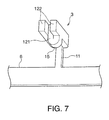
FIG. 7 is a perspective view of essential parts of the concentrated power-distribution member according to the another embodiment of this invention as seen from another direction; and -
FIG. 8 is a plan view of the concentrated power-distribution member before bending according to the another embodiment of this disclosure. - Referring to
FIG. 1 of the drawings, a concentrated power-distribution member according to an embodiment of this disclosure is applied to a power-distributing portion 1 of a stator of a three-phase alternating current concentrated winding motor. - The stator is provided with a plurality of stator coils in an inner side of the power-distributing portion 1 in the figure. The power-distributing portion 1 is provided with a plurality of sets of
coil connection terminals 3 as many as the number obtained by dividing a total number of the stator coils by three, which is the number of phases of the alternating current. Each set of thecoil connection terminals 3 comprises a total of fourcoil connection terminals 3 including threecoil connection terminals 3 connected to one ends of U-phase, V-phase, and W-phase coils, and a single neutral-phasecoil connection terminal 3 connected to the another ends of the U-phase, V-phase, and W-phase coils. - The
coil connection terminals 3 for each phase are connected to acommon busbar 6. Thebusbar 6 is a ring-shaped member. Fourbusbars 6 for a U-phase, a V-phase, a W-phase, and a neutral phase are held in annular grooves of acylindrical holding member 2 formed of an insulating material in a state where thebusbars 6 are insulated with each other. - The U-phase, V-phase, and W-
phase busbars 6 are connected to corresponding feed lines of each phase via busbar powerelectric terminals 5 fixed to theholding member 2. - The power-distributing portion 1 is fixed to a motor casing using bolts inserted through
installation bosses 4. - Referring to
FIG. 2 , thebusbars 6 of each phase have a partially cut ring shape. Eachbusbar 6 is provided with a single busbar powerelectric terminal 5 and a plurality ofcoil connection terminals 3 arranged with a constant angular interval. The busbar powerelectric terminal 5 is provided with abolt hole 7 for locking thebusbar 6 to theholding member 2. - Referring to
FIG. 3 , thecoil connection terminal 3 is formed in one-piece with thebusbar 6.FIG. 3 shows a case where thecoil connection terminal 3 is formed in one-piece with thebusbar 6 for the V-phase. Thebusbars 6 of each phase are fitted to the annular grooves formed in theholding member 2 concentrically with respect to a center axis. The center axis of thebusbar 6 corresponds to a rotation axis of the motor. Gaps between thebusbars 6 of each phase are insulated by a partitioningwall 8 that defines the annular groove. In addition, thebusbar 6 is fixed to the inside of the annular grove by an insulating resin material 9 filled in theholding member 2. A vertical direction in the figure refers to a direction of the center axis of thebusbar 6. - Referring to
FIG. 4 , each of thecoil connection terminals 3 comprises anerected portion 11 extending from thebusbar 6 in parallel with the center axis and a pair ofarms 12 extending toward the center axis from theerected portion 11. The pair ofarms 12 comprises abase portion 12A, anarrow portion 12B, and aholding portion 12C. - The pair of
arms 12 is formed by bending wing-like members protruding from both sides of theerected portion 11 in tangential directions of thebusbar 6, along a bending line parallel to the center axis of thebusbar 6 toward the center axis.Narrow portions 12B adjoining each other are formed in the middle of the pair ofarms 12. A portion extending from theerected portion 11 to thenarrow portion 12B corresponds to thebase portion 12A of the pair ofarms 12. In addition, a portion positioned in the leading end side from thenarrow portion 12B of the pair ofarms 12 corresponds to theholding portion 12C. Theholding portion 12C comprises forked leadingends 122 and abase end 121 closed by thenarrow portion 12B, thereby forming a U-shape. - Referring to
FIG. 5 , thecoil connection terminal 3 is formed in one-piece with thebusbar 6 together with the busbar powerelectric terminal 5 by cutting a band-shapedmember 100 in advance. That is, as illustrated inFIG. 5 , thewing portions 120 that form a pair ofarms 12 afterwards and theerected portion 11 are cut from thebusbar 6 in an approximately T-shape. The busbar powerelectric terminal 5 is also cut to protrude in the same direction. Thebusbar 6 thus formed in one-piece with the busbar powerelectric terminal 5 and a plurality ofcoil connection terminals 3 in advance is curved in a cylindrical shape and is fixed to the tubular groove of theholding member 2. The busbar powerelectric terminal 5 is bent by 90° toward the center axis of thebusbar 6. As a result, thebolt hole 7 overlaps the screw hole formed in a predetermined position of theholding member 2, and thebusbar 6 is positioned in theholding member 2 using a bolt installed through thebolt hole 7. - Meanwhile, the
coil connection terminal 3 is fabricated in the shape ofFIG. 4 through the following process. - First, the
wing portion 120 protruding from both side surfaces of theerected portion 11 to the side direction in parallel with thebusbar 6 is bent by 90° along the bending line parallel to the center axis of thebusbar 6 curved in a cylindrical shape. As a result, a pair ofarms 12 extending from theerected portion 11 toward the center axis is formed in thebusbar 6 in the cylindrical shape. Thenarrow portion 12B is formed by facing a pair ofarms 12 to each other and crimping middle portions of the pair ofarms 12 using a tool. As a result of formation of thenarrow portion 12B, thebase portion 12A and the holdingportion 12C are formed. - The concentrated power-distribution member including the
busbar 6, the busbar powerelectric terminal 5, and a plurality ofcoil connection terminals 3 formed in one-piece in this manner is prepared for each of the U-phase, the V-phase, and the W-phase and is fixed to the corresponding annular groove of the holdingmember 2. In addition, a concentrated power-distribution member including thebusbar 6 and a plurality ofcoil connection terminals 3 is prepared for a neutral phase and is fixed to the corresponding annular groove of the holdingmember 2. - It is noted that a length of the pair of
arms 12 is different depending on a position of the tubular groove inside the holdingmember 2. As the concentrated power-distribution member is arranged in the annular groove closer to the outer circumference of the holdingmember 2, a distance to the coil becomes long. Therefore, for the concentrated power-distribution member arranged in the annular groove closer to the outer circumference of the holdingmember 2, a length of thearm 12, specifically, thebase portion 12A of thearm 12 is set to be longer. - After the concentrated power-distribution members of each phase are fixed in this manner, the power-distributing portion 1 is fixed to the motor casing using bolts inserted through the
installation bosses 4. - A coil winding end is fixed to the holding
portion 12C as follows. Specifically, while the coil end is guided to the inner side of the fixingportion 12C having the U-shape, electrodes are connected to both outer sides of the forked leadingends 122, and a voltage is applied thereto. An electric current flows through thebase end 121 of the fixingportion 12C and generates heat due to an electric resistance of thebase end 121. This heat is transferred to the forked leadingends 122 and is used to melt a coat of the coil end. The coil obtained by removing the coat in this manner is fused to the forked leadingend 122. This process is called "fusing." - As described above, in the concentrated power-distribution member according to this invention, a pair of
arms 12 are obtained by forming a pair ofwing portions 120 extending to both sides from the erectedportion 11 that extends from thebusbar 6 in the direction along the rotation axis of the motor in advance, and bending thewing portions 120 toward the center axis along the bending line parallel to the center axis of thebusbar 6 curved in a cylindrical shape. In addition, the coilend holding portion 12C for fixing the coil end is provided in the leading ends of a pair ofarms 12. - According to this construction, there is no portion protruding from the erected
portion 11 in the direction of the center axis in the pair ofarms 12. The coilend holding portion 12C provided in the leading end of the pair ofarms 12 also does not protrude farther from the erectedportion 11 in the direction along the center axis. As a result, a dimension of thecoil connection terminal 3 in direction of the rotation axis of the motor is substantially equal to the dimension of the erectedportion 11 in the same direction. Therefore, it is possible to suppress the dimension of the concentrated power-distribution member in the direction of the rotation axis. - As a result, a preferable effect is obtained in miniaturizing the concentrated winding motor that uses the concentrated power-distribution member. Since the
coil connection terminal 3 has a simple shape having less bending portions, a structure of the concentrated power-distribution member is simplified. This makes it possible to reduce a manufacturing cost of the concentrated power-distribution member. - Further, the
narrow portion 12B and thebase end 121 of the holdingportion 12C are formed by crimping the middle of the pair ofarms 12, it is possible to easily form the holdingportion 12C for fixing the coil end. Since the concentrated power-distribution member including thebusbar 6 and the plurality ofcoil connection terminals 3 is formed by cutting a single sheet of the band-shapedmember 100, it is possible to form the concentrated power-distribution member with a low cost. Moreover, as illustrated inFIG. 5 , at the time of cutting, thearm 12 exists as thewing portion 120 protruding to the side direction from the erectedportion 11. For this reason, it is not necessary to increase a width of the band-shapedmember 100 for forming thearm 12. This also contributes to a reduction in a manufacturing cost of the concentrated power-distribution member. - Next, another embodiment of this invention will be described.
- Referring to
FIGS. 6 and7 , the concentrated power-distribution member according to this embodiment is provided with afolding portion 15 in one of thearms 12 of thecoil connection terminal 3. - In the first embodiment, the
narrow portion 12B formed in a pair ofarms 12 of thecoil connection terminal 3 serves as thebase end 121 of the holdingportion 12C. However, according to this embodiment, the foldingportion 15 serves as thebase end 121 of the holdingportion 12C. - Referring to
FIG. 8 , similar to the first embodiment, thecoil connection terminal 3 is formed in one-piece with thebusbar 6 by cutting the band-shapedmember 100. In this case, aprotrusion 150 protruding toward thebusbar 6 is formed as thefolding portion 15 in one of thewing portions 120. When the pair ofarms 12 is formed by bending thewing portions 120 protruding to the side direction from both sides of the erectedportion 11 to be in parallel with each other, theprotrusion 150 is folded in a U-shape such that a leading end of theprotrusion 150 is inserted into a gap between the pair ofarms 12. The foldingportion 15 formed in this manner serves as abase end 121 of the holdingportion 12C. - In this case, since the
folding portion 15 and thearm 12 that does not have theprotrusion 150 are not fixed to each other, an electric resistance increases in a contact portion. However, in the fusing process described above for fixing the coil winding end to the holdingportion 12C, if an inward pressure is applied from both outer sides of theleading end 122 when a voltage is applied to the forked leadingends 122 of the holdingportion 12C, a contact resistance between the foldingportion 15 and thearm 12 that does not have theprotrusion 150 is reduced so that fusing can be performed. - According to this embodiment, a crimping process for forming the
narrow portion 12B is not necessary. In addition, theprotrusion 150 for thefolding portion 15 is formed to extend from thewing portion 120 toward thebusbar 6 when the concentrated power-distribution member is formed by cutting the band-shapedmember 100. Therefore, the foldingportion 15 can be formed without increasing a width of the band-shapedmember 100. - The contents of Tokugan
2012-40256 - Although the invention has been described above with reference to certain embodiments, the invention is not limited to the embodiments described above. Modifications and variations of the embodiments described above will occur to those skilled in the art, within the scope of the claims.
- For example, the
folding portions 15 may be formed in both the pair ofarms 12. In this case, when the pair ofarms 12 are formed by bending a pair ofwing portions 120, theprotrusions 150 serving as thefolding portions 15 are folded such that each of theprotrusions 150 is inserted into the inner side of the pair ofarms 12. - As described above, this invention makes it possible to reduce a dimension of the concentrated winding motor in the direction of the rotation axis. Such a concentrated winding motor is particularly advantageous when it is mounted on a vehicle having a limited space.
- The embodiments of this invention in which an exclusive property or privilege is claimed are defined as follows:
Claims (6)
- A concentrated power-distribution member for a concentrated winding motor, comprising:a ring-shaped busbar having a center axis; anda coil connection terminal formed in one-piece with the busbar to hold a coil winding end positioned in an inner side of the busbar,wherein the coil connection terminal comprises
an erected portion that extends from the busbar in parallel with the center axis, the erected portion having a leading end and;
a pair of arms extending from the leading end toward the center axis, the pair of arms being constituted by a pair of wing portions that extends from the leading end of the erected portion to both sides of a tangential direction of the busbar and are bent toward the center axis along a bending line parallel to the center axis; and
a coil end holding portion provided in the leading ends of the pair of arms. - The concentrated power-distribution member according to claim 1, wherein a narrow portion is formed by deforming a middle part of the pair of arms to adjoin each other to cause the coil end holding portion to be provided in the leading end sides of the pair of arms from the narrow portion and form a fork-shape.
- The concentrated power-distribution member according to claim 1, wherein the coil connection terminal further comprises a folding portion in a shape of a folded protrusion that protrudes from the pair of wing portions and folded into a U-shape to cause a leading end of the folding portion to be gripped by the pair of arms, and the coil end holding portion is formed in the arms of the leading end side from the folding portion.
- The concentrated power-distribution member according to claim 3, wherein the protrusion is constructed by a member protruding toward the busbar from one of the pair of wing portions.
- The concentrated power-distribution member according to any one of claims 1 to 4, wherein the busbar and the coil connection terminal are formed as a band-shaped member cut and bent in a predetermined shape.
- A method of manufacturing a concentrated power-distribution member for a concentrated winding motor, the concentrated power-distribution member comprising a ring-shaped busbar having a center axis, a coil connection terminal formed in one-piece with the busbar to hold a coil winding end positioned in an inner side of the busbar, an erected portion that extends in parallel with the rotation axis from the busbar and has a leading end and, and a pair of arms extending from the leading end toward the center axis, the method comprising:forming a pair of wing portions extending to both sides of a tangential direction of the busbar from the leading end of the erected portion in advance;forming a pair of arms by bending the pair of wing portions toward the center axis along a bending line parallel to the center axis; andproviding a coil end holding portion in the leading ends of the pair of arms.
Applications Claiming Priority (2)
| Application Number | Priority Date | Filing Date | Title |
|---|---|---|---|
| JP2012040256 | 2012-02-27 | ||
| PCT/JP2013/054902 WO2013129377A1 (en) | 2012-02-27 | 2013-02-26 | Concentrated distribution member and manufacturing method therefor |
Publications (3)
| Publication Number | Publication Date |
|---|---|
| EP2822152A1 true EP2822152A1 (en) | 2015-01-07 |
| EP2822152A4 EP2822152A4 (en) | 2016-01-27 |
| EP2822152B1 EP2822152B1 (en) | 2016-09-28 |
Family
ID=49082574
Family Applications (1)
| Application Number | Title | Priority Date | Filing Date |
|---|---|---|---|
| EP13755074.5A Not-in-force EP2822152B1 (en) | 2012-02-27 | 2013-02-26 | Concentrated power-distribution member for concentrated winding motor |
Country Status (5)
| Country | Link |
|---|---|
| US (1) | US9484782B2 (en) |
| EP (1) | EP2822152B1 (en) |
| JP (1) | JP5773057B2 (en) |
| CN (1) | CN104137393B (en) |
| WO (1) | WO2013129377A1 (en) |
Cited By (1)
| Publication number | Priority date | Publication date | Assignee | Title |
|---|---|---|---|---|
| WO2016177536A1 (en) * | 2015-05-04 | 2016-11-10 | Zf Friedrichshafen Ag | Stator for an electrical machine having a potted interconnection device, and electrical machine having such a stator |
Families Citing this family (15)
| Publication number | Priority date | Publication date | Assignee | Title |
|---|---|---|---|---|
| JP6073703B2 (en) * | 2013-02-22 | 2017-02-01 | 住友電装株式会社 | Centralized power distribution member of motor |
| JP6073702B2 (en) * | 2013-02-22 | 2017-02-01 | 住友電装株式会社 | Centralized power distribution member of motor |
| JP6262163B2 (en) * | 2014-03-14 | 2018-01-17 | サンコール株式会社 | Bus ring unit |
| JP6307326B2 (en) * | 2014-03-31 | 2018-04-04 | 本田技研工業株式会社 | Rotating electric machine stator |
| JP6540172B2 (en) * | 2015-04-07 | 2019-07-10 | 日産自動車株式会社 | Manufacturing method of bus ring |
| EP3343737B1 (en) * | 2015-08-27 | 2020-08-19 | Nissan Motor Co., Ltd. | Method for manufacturing terminal member, method for connecting terminal member and conductive member, terminal member, and wiring member |
| DE102016209523A1 (en) | 2016-06-01 | 2017-12-07 | Zf Friedrichshafen Ag | Stator of an electrical machine with a connection device for stator coils and electrical machine with such a stator |
| DE102016224542A1 (en) * | 2016-12-08 | 2018-06-14 | Bayerische Motoren Werke Aktiengesellschaft | Switching ring for a stator of a rotary electric machine |
| DE112018005525T5 (en) * | 2017-09-28 | 2020-07-02 | Nidec Corporation | ENGINE AND METHOD FOR PRODUCING THE ENGINE |
| DE102018102033A1 (en) * | 2018-01-30 | 2019-08-01 | Ebm-Papst St. Georgen Gmbh & Co. Kg | Stator device with interconnected end plate for an electric motor and use of the stator device |
| DE102020000232A1 (en) * | 2020-01-16 | 2021-07-22 | Wieland-Werke Aktiengesellschaft | Contact device of a stator, stator and electrical machine |
| JP7441072B2 (en) * | 2020-02-25 | 2024-02-29 | 株式会社Subaru | stator |
| US11626766B2 (en) * | 2020-05-22 | 2023-04-11 | Hitachi Astemo, Ltd. | Power connection with overmolded axially adjusted connecting rings |
| KR102488606B1 (en) * | 2020-07-21 | 2023-01-13 | 현대모비스 주식회사 | Bus bar unit for motor |
| JP2024142040A (en) * | 2023-03-29 | 2024-10-10 | 愛知電機株式会社 | Electric motor |
Family Cites Families (8)
| Publication number | Priority date | Publication date | Assignee | Title |
|---|---|---|---|---|
| JPH06233483A (en) * | 1993-01-29 | 1994-08-19 | Honda Motor Co Ltd | Connection structure of coil winding in stator |
| DE19924325A1 (en) | 1998-06-19 | 1999-12-23 | Mannesmann Sachs Ag | Coil connection device for rotary electrical machine winding coils |
| JP2008312393A (en) * | 2007-06-15 | 2008-12-25 | Asmo Co Ltd | Bus bar device and brushless motor |
| JP4340740B2 (en) | 2007-07-19 | 2009-10-07 | トヨタ自動車株式会社 | Connection wire used for stator of electric motor, stator provided with the connection wire, and method of bending the connection wire |
| JP4924595B2 (en) * | 2008-12-09 | 2012-04-25 | 日産自動車株式会社 | Concentrated power distribution member for concentrated winding motor |
| US7806711B2 (en) * | 2009-02-27 | 2010-10-05 | American Power Conversion Corporation | Electrical connector |
| KR101146447B1 (en) * | 2010-11-22 | 2012-05-18 | 뉴모텍(주) | Bus-bar having connection tap for improving coil connection |
| JP5991172B2 (en) * | 2012-06-07 | 2016-09-14 | 日立金属株式会社 | Manufacturing method of electric motor |
-
2013
- 2013-02-26 EP EP13755074.5A patent/EP2822152B1/en not_active Not-in-force
- 2013-02-26 US US14/379,607 patent/US9484782B2/en not_active Expired - Fee Related
- 2013-02-26 WO PCT/JP2013/054902 patent/WO2013129377A1/en not_active Ceased
- 2013-02-26 JP JP2014502239A patent/JP5773057B2/en not_active Expired - Fee Related
- 2013-02-26 CN CN201380011261.7A patent/CN104137393B/en not_active Expired - Fee Related
Cited By (4)
| Publication number | Priority date | Publication date | Assignee | Title |
|---|---|---|---|---|
| WO2016177536A1 (en) * | 2015-05-04 | 2016-11-10 | Zf Friedrichshafen Ag | Stator for an electrical machine having a potted interconnection device, and electrical machine having such a stator |
| CN107580744A (en) * | 2015-05-04 | 2018-01-12 | Zf腓特烈斯哈芬股份公司 | Stator for electric machine with casted terminal arrangement and electric machine with such stator |
| CN107580744B (en) * | 2015-05-04 | 2020-03-13 | Zf腓特烈斯哈芬股份公司 | Stator for an electric machine and electric machine having such a stator |
| DE102015208186B4 (en) | 2015-05-04 | 2023-06-07 | Zf Friedrichshafen Ag | Stator for an electrical machine with a cast connection device and electrical machine with such a stator |
Also Published As
| Publication number | Publication date |
|---|---|
| US20150008775A1 (en) | 2015-01-08 |
| JPWO2013129377A1 (en) | 2015-07-30 |
| EP2822152B1 (en) | 2016-09-28 |
| CN104137393B (en) | 2016-11-09 |
| WO2013129377A1 (en) | 2013-09-06 |
| US9484782B2 (en) | 2016-11-01 |
| WO2013129377A9 (en) | 2013-10-24 |
| EP2822152A4 (en) | 2016-01-27 |
| JP5773057B2 (en) | 2015-09-02 |
| CN104137393A (en) | 2014-11-05 |
Similar Documents
| Publication | Publication Date | Title |
|---|---|---|
| EP2822152B1 (en) | Concentrated power-distribution member for concentrated winding motor | |
| EP3007319B1 (en) | Rotary electric machine, and manufacturing method therefor | |
| EP2182614B1 (en) | Wiring component for motor coil | |
| EP3154162B1 (en) | Terminal block connection structure in rotary electric machine | |
| US9318814B2 (en) | Wire connection member, wire connection structure and annular power distribution member | |
| JP5652004B2 (en) | Distribution structure parts and manufacturing method thereof | |
| EP3476021B1 (en) | Stator and motor having the same | |
| US9419487B2 (en) | Rotary electric machine | |
| US9577498B2 (en) | Stator for rotary electric machine and method for manufacturing the stator | |
| CN104335456B (en) | The manufacture method of stator and stator | |
| EP3038235A1 (en) | Rotary electric machine stator and manufacturing method of same | |
| US9887601B2 (en) | Stator of rotary electric machine | |
| JP2014079090A (en) | Bus ring for rotary electric machine stator | |
| US20230208237A1 (en) | Terminal device for a stator of an electric machine, electric drive for a vehicle and method for manufacturing an electric drive for a vehicle | |
| US8659201B2 (en) | Stator for electric rotating machine | |
| EP3079233A1 (en) | Electric power collection/distribution ring and electric motor | |
| JP5818771B2 (en) | Rotating electric machine stator | |
| JP4465396B2 (en) | Distribution connection structure for rotating electrical machine and method for manufacturing distribution connection structure for rotating electrical machine | |
| US9124158B2 (en) | Phase separator insulator for electric machine stator | |
| EP3079232A1 (en) | Electric power collection/distribution ring and electric motor | |
| JP2024125747A (en) | Armature | |
| KR20200079641A (en) | Motor |
Legal Events
| Date | Code | Title | Description |
|---|---|---|---|
| PUAI | Public reference made under article 153(3) epc to a published international application that has entered the european phase |
Free format text: ORIGINAL CODE: 0009012 |
|
| 17P | Request for examination filed |
Effective date: 20140926 |
|
| AK | Designated contracting states |
Kind code of ref document: A1 Designated state(s): AL AT BE BG CH CY CZ DE DK EE ES FI FR GB GR HR HU IE IS IT LI LT LU LV MC MK MT NL NO PL PT RO RS SE SI SK SM TR |
|
| AX | Request for extension of the european patent |
Extension state: BA ME |
|
| DAX | Request for extension of the european patent (deleted) | ||
| RA4 | Supplementary search report drawn up and despatched (corrected) |
Effective date: 20160108 |
|
| RIC1 | Information provided on ipc code assigned before grant |
Ipc: H02K 3/52 20060101AFI20151223BHEP |
|
| REG | Reference to a national code |
Ref country code: DE Ref legal event code: R079 Ref document number: 602013012211 Country of ref document: DE Free format text: PREVIOUS MAIN CLASS: H02K0003180000 Ipc: H02K0003520000 |
|
| GRAP | Despatch of communication of intention to grant a patent |
Free format text: ORIGINAL CODE: EPIDOSNIGR1 |
|
| RIC1 | Information provided on ipc code assigned before grant |
Ipc: H01R 39/32 20060101ALN20160411BHEP Ipc: H02K 3/52 20060101AFI20160411BHEP |
|
| INTG | Intention to grant announced |
Effective date: 20160519 |
|
| GRAS | Grant fee paid |
Free format text: ORIGINAL CODE: EPIDOSNIGR3 |
|
| GRAA | (expected) grant |
Free format text: ORIGINAL CODE: 0009210 |
|
| RAP1 | Party data changed (applicant data changed or rights of an application transferred) |
Owner name: NISSAN MOTOR CO., LTD. |
|
| RIN1 | Information on inventor provided before grant (corrected) |
Inventor name: ARAI, KENJI |
|
| AK | Designated contracting states |
Kind code of ref document: B1 Designated state(s): AL AT BE BG CH CY CZ DE DK EE ES FI FR GB GR HR HU IE IS IT LI LT LU LV MC MK MT NL NO PL PT RO RS SE SI SK SM TR |
|
| REG | Reference to a national code |
Ref country code: GB Ref legal event code: FG4D |
|
| REG | Reference to a national code |
Ref country code: CH Ref legal event code: EP |
|
| REG | Reference to a national code |
Ref country code: AT Ref legal event code: REF Ref document number: 833497 Country of ref document: AT Kind code of ref document: T Effective date: 20161015 |
|
| REG | Reference to a national code |
Ref country code: IE Ref legal event code: FG4D |
|
| REG | Reference to a national code |
Ref country code: DE Ref legal event code: R096 Ref document number: 602013012211 Country of ref document: DE |
|
| REG | Reference to a national code |
Ref country code: LT Ref legal event code: MG4D |
|
| PG25 | Lapsed in a contracting state [announced via postgrant information from national office to epo] |
Ref country code: LT Free format text: LAPSE BECAUSE OF FAILURE TO SUBMIT A TRANSLATION OF THE DESCRIPTION OR TO PAY THE FEE WITHIN THE PRESCRIBED TIME-LIMIT Effective date: 20160928 Ref country code: RS Free format text: LAPSE BECAUSE OF FAILURE TO SUBMIT A TRANSLATION OF THE DESCRIPTION OR TO PAY THE FEE WITHIN THE PRESCRIBED TIME-LIMIT Effective date: 20160928 Ref country code: FI Free format text: LAPSE BECAUSE OF FAILURE TO SUBMIT A TRANSLATION OF THE DESCRIPTION OR TO PAY THE FEE WITHIN THE PRESCRIBED TIME-LIMIT Effective date: 20160928 Ref country code: HR Free format text: LAPSE BECAUSE OF FAILURE TO SUBMIT A TRANSLATION OF THE DESCRIPTION OR TO PAY THE FEE WITHIN THE PRESCRIBED TIME-LIMIT Effective date: 20160928 Ref country code: NO Free format text: LAPSE BECAUSE OF FAILURE TO SUBMIT A TRANSLATION OF THE DESCRIPTION OR TO PAY THE FEE WITHIN THE PRESCRIBED TIME-LIMIT Effective date: 20161228 |
|
| REG | Reference to a national code |
Ref country code: NL Ref legal event code: MP Effective date: 20160928 |
|
| REG | Reference to a national code |
Ref country code: AT Ref legal event code: MK05 Ref document number: 833497 Country of ref document: AT Kind code of ref document: T Effective date: 20160928 |
|
| REG | Reference to a national code |
Ref country code: FR Ref legal event code: PLFP Year of fee payment: 5 |
|
| PG25 | Lapsed in a contracting state [announced via postgrant information from national office to epo] |
Ref country code: SE Free format text: LAPSE BECAUSE OF FAILURE TO SUBMIT A TRANSLATION OF THE DESCRIPTION OR TO PAY THE FEE WITHIN THE PRESCRIBED TIME-LIMIT Effective date: 20160928 Ref country code: LV Free format text: LAPSE BECAUSE OF FAILURE TO SUBMIT A TRANSLATION OF THE DESCRIPTION OR TO PAY THE FEE WITHIN THE PRESCRIBED TIME-LIMIT Effective date: 20160928 Ref country code: GR Free format text: LAPSE BECAUSE OF FAILURE TO SUBMIT A TRANSLATION OF THE DESCRIPTION OR TO PAY THE FEE WITHIN THE PRESCRIBED TIME-LIMIT Effective date: 20161229 Ref country code: NL Free format text: LAPSE BECAUSE OF FAILURE TO SUBMIT A TRANSLATION OF THE DESCRIPTION OR TO PAY THE FEE WITHIN THE PRESCRIBED TIME-LIMIT Effective date: 20160928 |
|
| PG25 | Lapsed in a contracting state [announced via postgrant information from national office to epo] |
Ref country code: EE Free format text: LAPSE BECAUSE OF FAILURE TO SUBMIT A TRANSLATION OF THE DESCRIPTION OR TO PAY THE FEE WITHIN THE PRESCRIBED TIME-LIMIT Effective date: 20160928 Ref country code: RO Free format text: LAPSE BECAUSE OF FAILURE TO SUBMIT A TRANSLATION OF THE DESCRIPTION OR TO PAY THE FEE WITHIN THE PRESCRIBED TIME-LIMIT Effective date: 20160928 |
|
| PG25 | Lapsed in a contracting state [announced via postgrant information from national office to epo] |
Ref country code: SK Free format text: LAPSE BECAUSE OF FAILURE TO SUBMIT A TRANSLATION OF THE DESCRIPTION OR TO PAY THE FEE WITHIN THE PRESCRIBED TIME-LIMIT Effective date: 20160928 Ref country code: AT Free format text: LAPSE BECAUSE OF FAILURE TO SUBMIT A TRANSLATION OF THE DESCRIPTION OR TO PAY THE FEE WITHIN THE PRESCRIBED TIME-LIMIT Effective date: 20160928 Ref country code: PT Free format text: LAPSE BECAUSE OF FAILURE TO SUBMIT A TRANSLATION OF THE DESCRIPTION OR TO PAY THE FEE WITHIN THE PRESCRIBED TIME-LIMIT Effective date: 20170130 Ref country code: BG Free format text: LAPSE BECAUSE OF FAILURE TO SUBMIT A TRANSLATION OF THE DESCRIPTION OR TO PAY THE FEE WITHIN THE PRESCRIBED TIME-LIMIT Effective date: 20161228 Ref country code: PL Free format text: LAPSE BECAUSE OF FAILURE TO SUBMIT A TRANSLATION OF THE DESCRIPTION OR TO PAY THE FEE WITHIN THE PRESCRIBED TIME-LIMIT Effective date: 20160928 Ref country code: SM Free format text: LAPSE BECAUSE OF FAILURE TO SUBMIT A TRANSLATION OF THE DESCRIPTION OR TO PAY THE FEE WITHIN THE PRESCRIBED TIME-LIMIT Effective date: 20160928 Ref country code: CZ Free format text: LAPSE BECAUSE OF FAILURE TO SUBMIT A TRANSLATION OF THE DESCRIPTION OR TO PAY THE FEE WITHIN THE PRESCRIBED TIME-LIMIT Effective date: 20160928 Ref country code: IS Free format text: LAPSE BECAUSE OF FAILURE TO SUBMIT A TRANSLATION OF THE DESCRIPTION OR TO PAY THE FEE WITHIN THE PRESCRIBED TIME-LIMIT Effective date: 20170128 Ref country code: BE Free format text: LAPSE BECAUSE OF FAILURE TO SUBMIT A TRANSLATION OF THE DESCRIPTION OR TO PAY THE FEE WITHIN THE PRESCRIBED TIME-LIMIT Effective date: 20160928 Ref country code: ES Free format text: LAPSE BECAUSE OF FAILURE TO SUBMIT A TRANSLATION OF THE DESCRIPTION OR TO PAY THE FEE WITHIN THE PRESCRIBED TIME-LIMIT Effective date: 20160928 |
|
| REG | Reference to a national code |
Ref country code: DE Ref legal event code: R097 Ref document number: 602013012211 Country of ref document: DE |
|
| PG25 | Lapsed in a contracting state [announced via postgrant information from national office to epo] |
Ref country code: IT Free format text: LAPSE BECAUSE OF FAILURE TO SUBMIT A TRANSLATION OF THE DESCRIPTION OR TO PAY THE FEE WITHIN THE PRESCRIBED TIME-LIMIT Effective date: 20160928 |
|
| PG25 | Lapsed in a contracting state [announced via postgrant information from national office to epo] |
Ref country code: DK Free format text: LAPSE BECAUSE OF FAILURE TO SUBMIT A TRANSLATION OF THE DESCRIPTION OR TO PAY THE FEE WITHIN THE PRESCRIBED TIME-LIMIT Effective date: 20160928 |
|
| PLBE | No opposition filed within time limit |
Free format text: ORIGINAL CODE: 0009261 |
|
| STAA | Information on the status of an ep patent application or granted ep patent |
Free format text: STATUS: NO OPPOSITION FILED WITHIN TIME LIMIT |
|
| 26N | No opposition filed |
Effective date: 20170629 |
|
| PG25 | Lapsed in a contracting state [announced via postgrant information from national office to epo] |
Ref country code: MC Free format text: LAPSE BECAUSE OF FAILURE TO SUBMIT A TRANSLATION OF THE DESCRIPTION OR TO PAY THE FEE WITHIN THE PRESCRIBED TIME-LIMIT Effective date: 20160928 |
|
| REG | Reference to a national code |
Ref country code: CH Ref legal event code: PL |
|
| PG25 | Lapsed in a contracting state [announced via postgrant information from national office to epo] |
Ref country code: CH Free format text: LAPSE BECAUSE OF NON-PAYMENT OF DUE FEES Effective date: 20170228 Ref country code: LI Free format text: LAPSE BECAUSE OF NON-PAYMENT OF DUE FEES Effective date: 20170228 |
|
| REG | Reference to a national code |
Ref country code: IE Ref legal event code: MM4A |
|
| PG25 | Lapsed in a contracting state [announced via postgrant information from national office to epo] |
Ref country code: SI Free format text: LAPSE BECAUSE OF FAILURE TO SUBMIT A TRANSLATION OF THE DESCRIPTION OR TO PAY THE FEE WITHIN THE PRESCRIBED TIME-LIMIT Effective date: 20160928 |
|
| PG25 | Lapsed in a contracting state [announced via postgrant information from national office to epo] |
Ref country code: LU Free format text: LAPSE BECAUSE OF NON-PAYMENT OF DUE FEES Effective date: 20170226 |
|
| REG | Reference to a national code |
Ref country code: FR Ref legal event code: PLFP Year of fee payment: 6 |
|
| PG25 | Lapsed in a contracting state [announced via postgrant information from national office to epo] |
Ref country code: IE Free format text: LAPSE BECAUSE OF NON-PAYMENT OF DUE FEES Effective date: 20170226 |
|
| PG25 | Lapsed in a contracting state [announced via postgrant information from national office to epo] |
Ref country code: MT Free format text: LAPSE BECAUSE OF NON-PAYMENT OF DUE FEES Effective date: 20170226 |
|
| PG25 | Lapsed in a contracting state [announced via postgrant information from national office to epo] |
Ref country code: AL Free format text: LAPSE BECAUSE OF FAILURE TO SUBMIT A TRANSLATION OF THE DESCRIPTION OR TO PAY THE FEE WITHIN THE PRESCRIBED TIME-LIMIT Effective date: 20160928 |
|
| PG25 | Lapsed in a contracting state [announced via postgrant information from national office to epo] |
Ref country code: HU Free format text: LAPSE BECAUSE OF FAILURE TO SUBMIT A TRANSLATION OF THE DESCRIPTION OR TO PAY THE FEE WITHIN THE PRESCRIBED TIME-LIMIT; INVALID AB INITIO Effective date: 20130226 |
|
| PG25 | Lapsed in a contracting state [announced via postgrant information from national office to epo] |
Ref country code: CY Free format text: LAPSE BECAUSE OF FAILURE TO SUBMIT A TRANSLATION OF THE DESCRIPTION OR TO PAY THE FEE WITHIN THE PRESCRIBED TIME-LIMIT Effective date: 20160928 |
|
| PG25 | Lapsed in a contracting state [announced via postgrant information from national office to epo] |
Ref country code: MK Free format text: LAPSE BECAUSE OF FAILURE TO SUBMIT A TRANSLATION OF THE DESCRIPTION OR TO PAY THE FEE WITHIN THE PRESCRIBED TIME-LIMIT Effective date: 20160928 |
|
| PG25 | Lapsed in a contracting state [announced via postgrant information from national office to epo] |
Ref country code: TR Free format text: LAPSE BECAUSE OF FAILURE TO SUBMIT A TRANSLATION OF THE DESCRIPTION OR TO PAY THE FEE WITHIN THE PRESCRIBED TIME-LIMIT Effective date: 20160928 |
|
| PGFP | Annual fee paid to national office [announced via postgrant information from national office to epo] |
Ref country code: GB Payment date: 20200219 Year of fee payment: 8 Ref country code: DE Payment date: 20200211 Year of fee payment: 8 |
|
| PGFP | Annual fee paid to national office [announced via postgrant information from national office to epo] |
Ref country code: FR Payment date: 20200113 Year of fee payment: 8 |
|
| REG | Reference to a national code |
Ref country code: DE Ref legal event code: R119 Ref document number: 602013012211 Country of ref document: DE |
|
| GBPC | Gb: european patent ceased through non-payment of renewal fee |
Effective date: 20210226 |
|
| PG25 | Lapsed in a contracting state [announced via postgrant information from national office to epo] |
Ref country code: GB Free format text: LAPSE BECAUSE OF NON-PAYMENT OF DUE FEES Effective date: 20210226 Ref country code: FR Free format text: LAPSE BECAUSE OF NON-PAYMENT OF DUE FEES Effective date: 20210228 Ref country code: DE Free format text: LAPSE BECAUSE OF NON-PAYMENT OF DUE FEES Effective date: 20210901 |