EP2822086B1 - Liquid holding body for lithium secondary batteries, and lithium secondary battery - Google Patents
Liquid holding body for lithium secondary batteries, and lithium secondary battery Download PDFInfo
- Publication number
- EP2822086B1 EP2822086B1 EP12870046.5A EP12870046A EP2822086B1 EP 2822086 B1 EP2822086 B1 EP 2822086B1 EP 12870046 A EP12870046 A EP 12870046A EP 2822086 B1 EP2822086 B1 EP 2822086B1
- Authority
- EP
- European Patent Office
- Prior art keywords
- fibrous layer
- lithium secondary
- porosity
- electrolyte holder
- layer
- Prior art date
- Legal status (The legal status is an assumption and is not a legal conclusion. Google has not performed a legal analysis and makes no representation as to the accuracy of the status listed.)
- Active
Links
- WHXSMMKQMYFTQS-UHFFFAOYSA-N Lithium Chemical compound [Li] WHXSMMKQMYFTQS-UHFFFAOYSA-N 0.000 title claims description 68
- 229910052744 lithium Inorganic materials 0.000 title claims description 68
- 239000007788 liquid Substances 0.000 title 1
- 239000003792 electrolyte Substances 0.000 claims description 81
- 239000008151 electrolyte solution Substances 0.000 claims description 32
- 239000013543 active substance Substances 0.000 claims description 26
- 239000000463 material Substances 0.000 claims description 24
- 229910001416 lithium ion Inorganic materials 0.000 claims description 20
- HBBGRARXTFLTSG-UHFFFAOYSA-N Lithium ion Chemical compound [Li+] HBBGRARXTFLTSG-UHFFFAOYSA-N 0.000 claims description 18
- 229920003043 Cellulose fiber Polymers 0.000 claims description 16
- 239000003575 carbonaceous material Substances 0.000 claims description 12
- 238000010030 laminating Methods 0.000 claims description 8
- 239000004627 regenerated cellulose Substances 0.000 claims description 7
- 229920003002 synthetic resin Polymers 0.000 claims description 7
- 239000000057 synthetic resin Substances 0.000 claims description 7
- 238000010009 beating Methods 0.000 claims description 4
- 229910003002 lithium salt Inorganic materials 0.000 claims description 4
- 159000000002 lithium salts Chemical class 0.000 claims description 4
- 238000004804 winding Methods 0.000 claims description 4
- 229930014626 natural product Natural products 0.000 claims description 2
- 239000012466 permeate Substances 0.000 claims description 2
- 239000010410 layer Substances 0.000 description 155
- 239000000835 fiber Substances 0.000 description 25
- 230000000052 comparative effect Effects 0.000 description 21
- 239000003795 chemical substances by application Substances 0.000 description 20
- 210000001787 dendrite Anatomy 0.000 description 16
- OKTJSMMVPCPJKN-UHFFFAOYSA-N Carbon Chemical compound [C] OKTJSMMVPCPJKN-UHFFFAOYSA-N 0.000 description 15
- -1 polyethylene Polymers 0.000 description 14
- 239000000123 paper Substances 0.000 description 13
- 238000001556 precipitation Methods 0.000 description 11
- 239000011230 binding agent Substances 0.000 description 10
- 239000000203 mixture Substances 0.000 description 10
- 239000002904 solvent Substances 0.000 description 10
- 229910045601 alloy Inorganic materials 0.000 description 8
- 239000000956 alloy Substances 0.000 description 8
- 229910052799 carbon Inorganic materials 0.000 description 8
- 239000011888 foil Substances 0.000 description 8
- 239000000779 smoke Substances 0.000 description 8
- 239000011267 electrode slurry Substances 0.000 description 7
- RYGMFSIKBFXOCR-UHFFFAOYSA-N Copper Chemical compound [Cu] RYGMFSIKBFXOCR-UHFFFAOYSA-N 0.000 description 6
- 229910052782 aluminium Inorganic materials 0.000 description 6
- XAGFODPZIPBFFR-UHFFFAOYSA-N aluminium Chemical compound [Al] XAGFODPZIPBFFR-UHFFFAOYSA-N 0.000 description 6
- 239000011889 copper foil Substances 0.000 description 6
- 238000000034 method Methods 0.000 description 6
- 239000000843 powder Substances 0.000 description 6
- 239000004698 Polyethylene Substances 0.000 description 5
- 238000007599 discharging Methods 0.000 description 5
- 229920000573 polyethylene Polymers 0.000 description 5
- 239000002131 composite material Substances 0.000 description 4
- 239000006185 dispersion Substances 0.000 description 4
- 239000002657 fibrous material Substances 0.000 description 4
- 230000020169 heat generation Effects 0.000 description 4
- 229910052751 metal Inorganic materials 0.000 description 4
- 239000007773 negative electrode material Substances 0.000 description 4
- 235000011837 pasties Nutrition 0.000 description 4
- 239000003495 polar organic solvent Substances 0.000 description 4
- 239000007774 positive electrode material Substances 0.000 description 4
- 229910052493 LiFePO4 Inorganic materials 0.000 description 3
- 239000006230 acetylene black Substances 0.000 description 3
- 239000002041 carbon nanotube Substances 0.000 description 3
- 229910021393 carbon nanotube Inorganic materials 0.000 description 3
- 239000006258 conductive agent Substances 0.000 description 3
- 239000004020 conductor Substances 0.000 description 3
- 230000007423 decrease Effects 0.000 description 3
- 239000002184 metal Substances 0.000 description 3
- 230000001376 precipitating effect Effects 0.000 description 3
- 239000000243 solution Substances 0.000 description 3
- OIFBSDVPJOWBCH-UHFFFAOYSA-N Diethyl carbonate Chemical compound CCOC(=O)OCC OIFBSDVPJOWBCH-UHFFFAOYSA-N 0.000 description 2
- KMTRUDSVKNLOMY-UHFFFAOYSA-N Ethylene carbonate Chemical compound O=C1OCCO1 KMTRUDSVKNLOMY-UHFFFAOYSA-N 0.000 description 2
- 229910032387 LiCoO2 Inorganic materials 0.000 description 2
- 229910002097 Lithium manganese(III,IV) oxide Inorganic materials 0.000 description 2
- SECXISVLQFMRJM-UHFFFAOYSA-N N-Methylpyrrolidone Chemical compound CN1CCCC1=O SECXISVLQFMRJM-UHFFFAOYSA-N 0.000 description 2
- 239000004743 Polypropylene Substances 0.000 description 2
- 229920000297 Rayon Polymers 0.000 description 2
- XUIMIQQOPSSXEZ-UHFFFAOYSA-N Silicon Chemical compound [Si] XUIMIQQOPSSXEZ-UHFFFAOYSA-N 0.000 description 2
- RTAQQCXQSZGOHL-UHFFFAOYSA-N Titanium Chemical compound [Ti] RTAQQCXQSZGOHL-UHFFFAOYSA-N 0.000 description 2
- 229910000147 aluminium phosphate Inorganic materials 0.000 description 2
- 238000004364 calculation method Methods 0.000 description 2
- 229920002678 cellulose Polymers 0.000 description 2
- 239000001913 cellulose Substances 0.000 description 2
- 150000001875 compounds Chemical class 0.000 description 2
- 238000010276 construction Methods 0.000 description 2
- 238000000354 decomposition reaction Methods 0.000 description 2
- 230000003247 decreasing effect Effects 0.000 description 2
- 230000018109 developmental process Effects 0.000 description 2
- 238000001035 drying Methods 0.000 description 2
- 230000000694 effects Effects 0.000 description 2
- 239000007772 electrode material Substances 0.000 description 2
- 125000002573 ethenylidene group Chemical group [*]=C=C([H])[H] 0.000 description 2
- JBTWLSYIZRCDFO-UHFFFAOYSA-N ethyl methyl carbonate Chemical compound CCOC(=O)OC JBTWLSYIZRCDFO-UHFFFAOYSA-N 0.000 description 2
- 230000002349 favourable effect Effects 0.000 description 2
- 150000002222 fluorine compounds Chemical class 0.000 description 2
- 238000005470 impregnation Methods 0.000 description 2
- 239000012784 inorganic fiber Substances 0.000 description 2
- 238000004898 kneading Methods 0.000 description 2
- 239000002655 kraft paper Substances 0.000 description 2
- 238000003475 lamination Methods 0.000 description 2
- 229910021450 lithium metal oxide Inorganic materials 0.000 description 2
- 229910001496 lithium tetrafluoroborate Inorganic materials 0.000 description 2
- 229910044991 metal oxide Inorganic materials 0.000 description 2
- 150000004706 metal oxides Chemical class 0.000 description 2
- 229910052914 metal silicate Inorganic materials 0.000 description 2
- 230000005012 migration Effects 0.000 description 2
- 238000013508 migration Methods 0.000 description 2
- 238000002156 mixing Methods 0.000 description 2
- 239000010450 olivine Substances 0.000 description 2
- 229910052609 olivine Inorganic materials 0.000 description 2
- NBIIXXVUZAFLBC-UHFFFAOYSA-N phosphoric acid Substances OP(O)(O)=O NBIIXXVUZAFLBC-UHFFFAOYSA-N 0.000 description 2
- 229920005672 polyolefin resin Polymers 0.000 description 2
- 229920001155 polypropylene Polymers 0.000 description 2
- 239000002244 precipitate Substances 0.000 description 2
- 238000003825 pressing Methods 0.000 description 2
- RUOJZAUFBMNUDX-UHFFFAOYSA-N propylene carbonate Chemical compound CC1COC(=O)O1 RUOJZAUFBMNUDX-UHFFFAOYSA-N 0.000 description 2
- 239000002964 rayon Substances 0.000 description 2
- 229920005989 resin Polymers 0.000 description 2
- 239000011347 resin Substances 0.000 description 2
- 230000000452 restraining effect Effects 0.000 description 2
- 230000000717 retained effect Effects 0.000 description 2
- 238000011076 safety test Methods 0.000 description 2
- 229910052710 silicon Inorganic materials 0.000 description 2
- 239000010703 silicon Substances 0.000 description 2
- 239000006104 solid solution Substances 0.000 description 2
- 238000009987 spinning Methods 0.000 description 2
- 238000006467 substitution reaction Methods 0.000 description 2
- 239000004925 Acrylic resin Substances 0.000 description 1
- 229920000178 Acrylic resin Polymers 0.000 description 1
- 244000198134 Agave sisalana Species 0.000 description 1
- 235000011624 Agave sisalana Nutrition 0.000 description 1
- 229910000838 Al alloy Inorganic materials 0.000 description 1
- 235000017166 Bambusa arundinacea Nutrition 0.000 description 1
- 235000017491 Bambusa tulda Nutrition 0.000 description 1
- 229920000742 Cotton Polymers 0.000 description 1
- 229910000733 Li alloy Inorganic materials 0.000 description 1
- 229910009723 Li2FePO4 Inorganic materials 0.000 description 1
- 229910010085 Li2MnO3-LiMO2 Inorganic materials 0.000 description 1
- 229910010099 Li2MnO3—LiMO2 Inorganic materials 0.000 description 1
- 229910011279 LiCoPO4 Inorganic materials 0.000 description 1
- 229910010584 LiFeO2 Inorganic materials 0.000 description 1
- 229910010740 LiFeSiO4 Inorganic materials 0.000 description 1
- 229910000668 LiMnPO4 Inorganic materials 0.000 description 1
- 229910001290 LiPF6 Inorganic materials 0.000 description 1
- 229910000857 LiTi2(PO4)3 Inorganic materials 0.000 description 1
- 229920001407 Modal (textile) Polymers 0.000 description 1
- 240000000907 Musa textilis Species 0.000 description 1
- 244000082204 Phyllostachys viridis Species 0.000 description 1
- 235000015334 Phyllostachys viridis Nutrition 0.000 description 1
- VYPSYNLAJGMNEJ-UHFFFAOYSA-N Silicium dioxide Chemical compound O=[Si]=O VYPSYNLAJGMNEJ-UHFFFAOYSA-N 0.000 description 1
- NINIDFKCEFEMDL-UHFFFAOYSA-N Sulfur Chemical compound [S] NINIDFKCEFEMDL-UHFFFAOYSA-N 0.000 description 1
- ATJFFYVFTNAWJD-UHFFFAOYSA-N Tin Chemical compound [Sn] ATJFFYVFTNAWJD-UHFFFAOYSA-N 0.000 description 1
- GWEVSGVZZGPLCZ-UHFFFAOYSA-N Titan oxide Chemical compound O=[Ti]=O GWEVSGVZZGPLCZ-UHFFFAOYSA-N 0.000 description 1
- JFBZPFYRPYOZCQ-UHFFFAOYSA-N [Li].[Al] Chemical compound [Li].[Al] JFBZPFYRPYOZCQ-UHFFFAOYSA-N 0.000 description 1
- FDLZQPXZHIFURF-UHFFFAOYSA-N [O-2].[Ti+4].[Li+] Chemical compound [O-2].[Ti+4].[Li+] FDLZQPXZHIFURF-UHFFFAOYSA-N 0.000 description 1
- 239000002253 acid Substances 0.000 description 1
- 239000000654 additive Substances 0.000 description 1
- 230000000996 additive effect Effects 0.000 description 1
- 239000000853 adhesive Substances 0.000 description 1
- 230000001070 adhesive effect Effects 0.000 description 1
- 150000001412 amines Chemical class 0.000 description 1
- QVGXLLKOCUKJST-UHFFFAOYSA-N atomic oxygen Chemical compound [O] QVGXLLKOCUKJST-UHFFFAOYSA-N 0.000 description 1
- 239000011425 bamboo Substances 0.000 description 1
- 125000002915 carbonyl group Chemical group [*:2]C([*:1])=O 0.000 description 1
- 125000003178 carboxy group Chemical group [H]OC(*)=O 0.000 description 1
- 239000000919 ceramic Substances 0.000 description 1
- 238000004140 cleaning Methods 0.000 description 1
- 239000011248 coating agent Substances 0.000 description 1
- 238000000576 coating method Methods 0.000 description 1
- 229920001577 copolymer Polymers 0.000 description 1
- 125000004122 cyclic group Chemical group 0.000 description 1
- 230000018044 dehydration Effects 0.000 description 1
- 238000006297 dehydration reaction Methods 0.000 description 1
- 230000006866 deterioration Effects 0.000 description 1
- IEJIGPNLZYLLBP-UHFFFAOYSA-N dimethyl carbonate Chemical compound COC(=O)OC IEJIGPNLZYLLBP-UHFFFAOYSA-N 0.000 description 1
- 239000000428 dust Substances 0.000 description 1
- 230000005611 electricity Effects 0.000 description 1
- 238000009791 electrochemical migration reaction Methods 0.000 description 1
- 239000004744 fabric Substances 0.000 description 1
- UQSQSQZYBQSBJZ-UHFFFAOYSA-N fluorosulfonic acid Chemical group OS(F)(=O)=O UQSQSQZYBQSBJZ-UHFFFAOYSA-N 0.000 description 1
- 125000000524 functional group Chemical group 0.000 description 1
- 239000003365 glass fiber Substances 0.000 description 1
- 239000012535 impurity Substances 0.000 description 1
- 238000009413 insulation Methods 0.000 description 1
- 230000002427 irreversible effect Effects 0.000 description 1
- 239000001989 lithium alloy Substances 0.000 description 1
- GELKBWJHTRAYNV-UHFFFAOYSA-K lithium iron phosphate Chemical compound [Li+].[Fe+2].[O-]P([O-])([O-])=O GELKBWJHTRAYNV-UHFFFAOYSA-K 0.000 description 1
- MCVFFRWZNYZUIJ-UHFFFAOYSA-M lithium;trifluoromethanesulfonate Chemical compound [Li+].[O-]S(=O)(=O)C(F)(F)F MCVFFRWZNYZUIJ-UHFFFAOYSA-M 0.000 description 1
- 230000014759 maintenance of location Effects 0.000 description 1
- 229910052748 manganese Inorganic materials 0.000 description 1
- 150000002739 metals Chemical class 0.000 description 1
- 239000000178 monomer Substances 0.000 description 1
- 229910052759 nickel Inorganic materials 0.000 description 1
- 239000011255 nonaqueous electrolyte Substances 0.000 description 1
- 239000003960 organic solvent Substances 0.000 description 1
- 229910052760 oxygen Inorganic materials 0.000 description 1
- 239000001301 oxygen Substances 0.000 description 1
- 239000002245 particle Substances 0.000 description 1
- 230000000149 penetrating effect Effects 0.000 description 1
- 230000035699 permeability Effects 0.000 description 1
- 229920003207 poly(ethylene-2,6-naphthalate) Polymers 0.000 description 1
- 229920006122 polyamide resin Polymers 0.000 description 1
- 229920001707 polybutylene terephthalate Polymers 0.000 description 1
- 229920001225 polyester resin Polymers 0.000 description 1
- 239000004645 polyester resin Substances 0.000 description 1
- 239000011112 polyethylene naphthalate Substances 0.000 description 1
- 229920013716 polyethylene resin Polymers 0.000 description 1
- 229920000139 polyethylene terephthalate Polymers 0.000 description 1
- 239000005020 polyethylene terephthalate Substances 0.000 description 1
- 229920000642 polymer Polymers 0.000 description 1
- 238000006116 polymerization reaction Methods 0.000 description 1
- 229920000098 polyolefin Polymers 0.000 description 1
- 239000011148 porous material Substances 0.000 description 1
- 230000008929 regeneration Effects 0.000 description 1
- 238000011069 regeneration method Methods 0.000 description 1
- 230000002040 relaxant effect Effects 0.000 description 1
- 239000011163 secondary particle Substances 0.000 description 1
- 239000004065 semiconductor Substances 0.000 description 1
- 229910052814 silicon oxide Inorganic materials 0.000 description 1
- 239000002356 single layer Substances 0.000 description 1
- 239000002002 slurry Substances 0.000 description 1
- 229910021384 soft carbon Inorganic materials 0.000 description 1
- 238000003860 storage Methods 0.000 description 1
- 125000001273 sulfonato group Chemical group [O-]S(*)(=O)=O 0.000 description 1
- 125000000542 sulfonic acid group Chemical group 0.000 description 1
- 229910052717 sulfur Inorganic materials 0.000 description 1
- 239000011593 sulfur Substances 0.000 description 1
- 239000004094 surface-active agent Substances 0.000 description 1
- 239000000725 suspension Substances 0.000 description 1
- 238000010998 test method Methods 0.000 description 1
- OGIDPMRJRNCKJF-UHFFFAOYSA-N titanium oxide Inorganic materials [Ti]=O OGIDPMRJRNCKJF-UHFFFAOYSA-N 0.000 description 1
- 125000000391 vinyl group Chemical group [H]C([*])=C([H])[H] 0.000 description 1
- 229920002554 vinyl polymer Polymers 0.000 description 1
Images
Classifications
-
- H—ELECTRICITY
- H01—ELECTRIC ELEMENTS
- H01M—PROCESSES OR MEANS, e.g. BATTERIES, FOR THE DIRECT CONVERSION OF CHEMICAL ENERGY INTO ELECTRICAL ENERGY
- H01M10/00—Secondary cells; Manufacture thereof
- H01M10/05—Accumulators with non-aqueous electrolyte
- H01M10/058—Construction or manufacture
- H01M10/0585—Construction or manufacture of accumulators having only flat construction elements, i.e. flat positive electrodes, flat negative electrodes and flat separators
-
- H—ELECTRICITY
- H01—ELECTRIC ELEMENTS
- H01M—PROCESSES OR MEANS, e.g. BATTERIES, FOR THE DIRECT CONVERSION OF CHEMICAL ENERGY INTO ELECTRICAL ENERGY
- H01M10/00—Secondary cells; Manufacture thereof
- H01M10/04—Construction or manufacture in general
- H01M10/0431—Cells with wound or folded electrodes
-
- H—ELECTRICITY
- H01—ELECTRIC ELEMENTS
- H01M—PROCESSES OR MEANS, e.g. BATTERIES, FOR THE DIRECT CONVERSION OF CHEMICAL ENERGY INTO ELECTRICAL ENERGY
- H01M10/00—Secondary cells; Manufacture thereof
- H01M10/05—Accumulators with non-aqueous electrolyte
- H01M10/052—Li-accumulators
-
- H—ELECTRICITY
- H01—ELECTRIC ELEMENTS
- H01M—PROCESSES OR MEANS, e.g. BATTERIES, FOR THE DIRECT CONVERSION OF CHEMICAL ENERGY INTO ELECTRICAL ENERGY
- H01M10/00—Secondary cells; Manufacture thereof
- H01M10/05—Accumulators with non-aqueous electrolyte
- H01M10/052—Li-accumulators
- H01M10/0525—Rocking-chair batteries, i.e. batteries with lithium insertion or intercalation in both electrodes; Lithium-ion batteries
-
- H—ELECTRICITY
- H01—ELECTRIC ELEMENTS
- H01M—PROCESSES OR MEANS, e.g. BATTERIES, FOR THE DIRECT CONVERSION OF CHEMICAL ENERGY INTO ELECTRICAL ENERGY
- H01M10/00—Secondary cells; Manufacture thereof
- H01M10/05—Accumulators with non-aqueous electrolyte
- H01M10/056—Accumulators with non-aqueous electrolyte characterised by the materials used as electrolytes, e.g. mixed inorganic/organic electrolytes
- H01M10/0564—Accumulators with non-aqueous electrolyte characterised by the materials used as electrolytes, e.g. mixed inorganic/organic electrolytes the electrolyte being constituted of organic materials only
- H01M10/0566—Liquid materials
-
- H—ELECTRICITY
- H01—ELECTRIC ELEMENTS
- H01M—PROCESSES OR MEANS, e.g. BATTERIES, FOR THE DIRECT CONVERSION OF CHEMICAL ENERGY INTO ELECTRICAL ENERGY
- H01M10/00—Secondary cells; Manufacture thereof
- H01M10/05—Accumulators with non-aqueous electrolyte
- H01M10/058—Construction or manufacture
-
- H—ELECTRICITY
- H01—ELECTRIC ELEMENTS
- H01M—PROCESSES OR MEANS, e.g. BATTERIES, FOR THE DIRECT CONVERSION OF CHEMICAL ENERGY INTO ELECTRICAL ENERGY
- H01M10/00—Secondary cells; Manufacture thereof
- H01M10/05—Accumulators with non-aqueous electrolyte
- H01M10/058—Construction or manufacture
- H01M10/0587—Construction or manufacture of accumulators having only wound construction elements, i.e. wound positive electrodes, wound negative electrodes and wound separators
-
- H—ELECTRICITY
- H01—ELECTRIC ELEMENTS
- H01M—PROCESSES OR MEANS, e.g. BATTERIES, FOR THE DIRECT CONVERSION OF CHEMICAL ENERGY INTO ELECTRICAL ENERGY
- H01M4/00—Electrodes
- H01M4/02—Electrodes composed of, or comprising, active material
- H01M4/13—Electrodes for accumulators with non-aqueous electrolyte, e.g. for lithium-accumulators; Processes of manufacture thereof
- H01M4/133—Electrodes based on carbonaceous material, e.g. graphite-intercalation compounds or CFx
-
- H—ELECTRICITY
- H01—ELECTRIC ELEMENTS
- H01M—PROCESSES OR MEANS, e.g. BATTERIES, FOR THE DIRECT CONVERSION OF CHEMICAL ENERGY INTO ELECTRICAL ENERGY
- H01M4/00—Electrodes
- H01M4/02—Electrodes composed of, or comprising, active material
- H01M4/36—Selection of substances as active materials, active masses, active liquids
- H01M4/58—Selection of substances as active materials, active masses, active liquids of inorganic compounds other than oxides or hydroxides, e.g. sulfides, selenides, tellurides, halogenides or LiCoFy; of polyanionic structures, e.g. phosphates, silicates or borates
- H01M4/583—Carbonaceous material, e.g. graphite-intercalation compounds or CFx
- H01M4/587—Carbonaceous material, e.g. graphite-intercalation compounds or CFx for inserting or intercalating light metals
-
- H—ELECTRICITY
- H01—ELECTRIC ELEMENTS
- H01M—PROCESSES OR MEANS, e.g. BATTERIES, FOR THE DIRECT CONVERSION OF CHEMICAL ENERGY INTO ELECTRICAL ENERGY
- H01M50/00—Constructional details or processes of manufacture of the non-active parts of electrochemical cells other than fuel cells, e.g. hybrid cells
- H01M50/40—Separators; Membranes; Diaphragms; Spacing elements inside cells
- H01M50/409—Separators, membranes or diaphragms characterised by the material
- H01M50/411—Organic material
- H01M50/414—Synthetic resins, e.g. thermoplastics or thermosetting resins
-
- H—ELECTRICITY
- H01—ELECTRIC ELEMENTS
- H01M—PROCESSES OR MEANS, e.g. BATTERIES, FOR THE DIRECT CONVERSION OF CHEMICAL ENERGY INTO ELECTRICAL ENERGY
- H01M50/00—Constructional details or processes of manufacture of the non-active parts of electrochemical cells other than fuel cells, e.g. hybrid cells
- H01M50/40—Separators; Membranes; Diaphragms; Spacing elements inside cells
- H01M50/409—Separators, membranes or diaphragms characterised by the material
- H01M50/411—Organic material
- H01M50/429—Natural polymers
- H01M50/4295—Natural cotton, cellulose or wood
-
- H—ELECTRICITY
- H01—ELECTRIC ELEMENTS
- H01M—PROCESSES OR MEANS, e.g. BATTERIES, FOR THE DIRECT CONVERSION OF CHEMICAL ENERGY INTO ELECTRICAL ENERGY
- H01M50/00—Constructional details or processes of manufacture of the non-active parts of electrochemical cells other than fuel cells, e.g. hybrid cells
- H01M50/40—Separators; Membranes; Diaphragms; Spacing elements inside cells
- H01M50/409—Separators, membranes or diaphragms characterised by the material
- H01M50/44—Fibrous material
-
- H—ELECTRICITY
- H01—ELECTRIC ELEMENTS
- H01M—PROCESSES OR MEANS, e.g. BATTERIES, FOR THE DIRECT CONVERSION OF CHEMICAL ENERGY INTO ELECTRICAL ENERGY
- H01M50/00—Constructional details or processes of manufacture of the non-active parts of electrochemical cells other than fuel cells, e.g. hybrid cells
- H01M50/40—Separators; Membranes; Diaphragms; Spacing elements inside cells
- H01M50/409—Separators, membranes or diaphragms characterised by the material
- H01M50/449—Separators, membranes or diaphragms characterised by the material having a layered structure
-
- H—ELECTRICITY
- H01—ELECTRIC ELEMENTS
- H01M—PROCESSES OR MEANS, e.g. BATTERIES, FOR THE DIRECT CONVERSION OF CHEMICAL ENERGY INTO ELECTRICAL ENERGY
- H01M50/00—Constructional details or processes of manufacture of the non-active parts of electrochemical cells other than fuel cells, e.g. hybrid cells
- H01M50/40—Separators; Membranes; Diaphragms; Spacing elements inside cells
- H01M50/489—Separators, membranes, diaphragms or spacing elements inside the cells, characterised by their physical properties, e.g. swelling degree, hydrophilicity or shut down properties
- H01M50/491—Porosity
-
- H—ELECTRICITY
- H01—ELECTRIC ELEMENTS
- H01M—PROCESSES OR MEANS, e.g. BATTERIES, FOR THE DIRECT CONVERSION OF CHEMICAL ENERGY INTO ELECTRICAL ENERGY
- H01M4/00—Electrodes
- H01M4/02—Electrodes composed of, or comprising, active material
- H01M2004/026—Electrodes composed of, or comprising, active material characterised by the polarity
- H01M2004/027—Negative electrodes
-
- H—ELECTRICITY
- H01—ELECTRIC ELEMENTS
- H01M—PROCESSES OR MEANS, e.g. BATTERIES, FOR THE DIRECT CONVERSION OF CHEMICAL ENERGY INTO ELECTRICAL ENERGY
- H01M50/00—Constructional details or processes of manufacture of the non-active parts of electrochemical cells other than fuel cells, e.g. hybrid cells
- H01M50/40—Separators; Membranes; Diaphragms; Spacing elements inside cells
- H01M50/409—Separators, membranes or diaphragms characterised by the material
- H01M50/431—Inorganic material
- H01M50/434—Ceramics
- H01M50/437—Glass
-
- H—ELECTRICITY
- H01—ELECTRIC ELEMENTS
- H01M—PROCESSES OR MEANS, e.g. BATTERIES, FOR THE DIRECT CONVERSION OF CHEMICAL ENERGY INTO ELECTRICAL ENERGY
- H01M50/00—Constructional details or processes of manufacture of the non-active parts of electrochemical cells other than fuel cells, e.g. hybrid cells
- H01M50/40—Separators; Membranes; Diaphragms; Spacing elements inside cells
- H01M50/489—Separators, membranes, diaphragms or spacing elements inside the cells, characterised by their physical properties, e.g. swelling degree, hydrophilicity or shut down properties
-
- Y—GENERAL TAGGING OF NEW TECHNOLOGICAL DEVELOPMENTS; GENERAL TAGGING OF CROSS-SECTIONAL TECHNOLOGIES SPANNING OVER SEVERAL SECTIONS OF THE IPC; TECHNICAL SUBJECTS COVERED BY FORMER USPC CROSS-REFERENCE ART COLLECTIONS [XRACs] AND DIGESTS
- Y02—TECHNOLOGIES OR APPLICATIONS FOR MITIGATION OR ADAPTATION AGAINST CLIMATE CHANGE
- Y02E—REDUCTION OF GREENHOUSE GAS [GHG] EMISSIONS, RELATED TO ENERGY GENERATION, TRANSMISSION OR DISTRIBUTION
- Y02E60/00—Enabling technologies; Technologies with a potential or indirect contribution to GHG emissions mitigation
- Y02E60/10—Energy storage using batteries
-
- Y—GENERAL TAGGING OF NEW TECHNOLOGICAL DEVELOPMENTS; GENERAL TAGGING OF CROSS-SECTIONAL TECHNOLOGIES SPANNING OVER SEVERAL SECTIONS OF THE IPC; TECHNICAL SUBJECTS COVERED BY FORMER USPC CROSS-REFERENCE ART COLLECTIONS [XRACs] AND DIGESTS
- Y02—TECHNOLOGIES OR APPLICATIONS FOR MITIGATION OR ADAPTATION AGAINST CLIMATE CHANGE
- Y02P—CLIMATE CHANGE MITIGATION TECHNOLOGIES IN THE PRODUCTION OR PROCESSING OF GOODS
- Y02P70/00—Climate change mitigation technologies in the production process for final industrial or consumer products
- Y02P70/50—Manufacturing or production processes characterised by the final manufactured product
Definitions
- the present invention relates to a holder for holding an electrolyte for use in a lithium secondary battery and the lithium secondary battery using the holder.
- the lithium secondary battery formed by using a material capable of absorbing and discharging lithium ions is capable of restraining precipitation of dendrite to a higher extent than a lithium battery in which the negative electrode is formed by using metallic lithium. Therefore the lithium secondary battery has been supplied to the market as a battery having enhanced safety.
- the development of the lithium secondary battery is advanced for industrial use including a case in which the lithium secondary battery is mounted on a vehicle and a case in which it is used as a stationary power source. It is a big problem to allow the lithium secondary battery to have a high output (in charging and discharging it at high current) and a long life, even though it is repeatingly charged and discharged at high current.
- the above-described devices have improved the performance of the lithium secondary battery in allowing the lithium secondary battery to be charged and discharged at high current, but were insufficient as a measure for prolonging the life of the lithium secondary battery. Therefore the substitution mixing ratio of metal elements of lithium metal oxides used to form the positive electrode and substitution of doped metals have been investigated.
- an alloy composition the addition of a conductive material, and a binding agent devised to restrain the volume expansion of an alloy.
- a separator to be interposed between the cathode and the anode a polyethylene film having a porosity of about 40% is mainly used.
- JP-A-2007018861 discloses a separator for battery, the porosity of the separator is changed in thickness direction of the separator.
- JP-A-2011233354 discloses a separator comprising a center part, and a surface part whose porosity is larger than that of the center part 2.
- the above-described proposed means as disclosed in the patent document 1 are capable of increasing the cycle life up to 2000 to 3000 cycle level from hundreds of cycles, the means are insufficient for increasing the cycle life to 10 to 20 years and 10000 to 20000 cycles in the case where the lithium secondary battery is used to mount it on vehicles or stationary.
- a method of relaxing the volume expansion of the alloy by increasing the adhesive force of the binding agent of the alloy-based negative electrode there is an increase in the use amount of the binding agent when it is used as the technique of making the active substance consisting of the alloy fine and preventing the active substance from separating from the electricity collection foil.
- a produced battery does not meet a designed capacity, and the cost increases.
- it is difficult for the proposed means to satisfy the demanded performance to such an extent that batteries can be used for industrial application.
- the cellulose fibers excellent in its impregnation property are utilized as the separator.
- the separator consisting of the cellulose easily holds the electrolytic solution as compared with the separator consisting of the polyethylene film.
- the separator has a single-layer construction having a constant porosity, the porosity thereof cannot be adjusted at the interface between the separator and the positive and negative electrodes in conformity to the properties of the positive and negative electrodes, and the electrolytic solution is liable to migrate to a battery can. Thereby there is a case in which solution shortage cannot be sufficiently prevented.
- the art disclosed in the patent document 2 assumes that the lithium titanium oxide, having a lithium ion occlusion potential of not less than 0.2V (vs. Li/Li + ), which is capable of preventing the precipitation of dendrite is used as the negative electrode active substance.
- a negative electrode active substance such as a carbon material is used.
- the present invention has been made to cope with the above-described problems. It is an object of the present invention to provide an electrolyte holder for a lithium secondary battery capable of holding an electrolytic solution inside electrodes or at an interface between a separator and each of the electrodes, preventing solution shortage inside the electrodes, and restraining dendrite from precipitating and growing and also provide the lithium secondary battery, using the electrolyte holder, which is capable of achieving a cycle life to such an extent that the lithium secondary battery can be used for industrial application.
- the invention provides and electrolyte holder as claimed in claim 1 and a lithium secondary battery including the electrolyte holder as claimed in claim 9.
- a porosity of a fibrous layer A constructing an interface between the fibrous layer A and the anode is set to 50% to 60%
- a porosity of a fibrous layer B constructing an interface between the fibrous layer B and the cathode is set to 70% to 80%.
- the electrolyte holder has (1) a two-layer structure consisting of the fibrous layer A and the fibrous layer B or (2) a three-layer structure consisting of the fibrous layer A, the fibrous layer B, and a film layer, made of synthetic resin, which is disposed between the fibrous layer A and the fibrous layer B.
- the fibrous layers are formed by using beaten regenerated fibers as a main material thereof.
- An active substance for use in the anode is a carbon material.
- the electrolyte holder of the present invention for the lithium secondary battery has a multi-layer structure composed of at least two hydrophilic fibrous layers having different porosities.
- the average porosity of the entire fibrous layer is set to not less than 50% and is thus higher than that of conventional film separators. Therefore the electrolyte holder of the present invention is capable of holding a larger amount of the electrolytic solution than the conventional film separators.
- the electrolyte holder of the present invention has the multi-layer structure having fibrous layers composed of different porosities. Therefore according to the properties of the active substance surfaces of the electrode plates, it is possible to appropriately set the porosities of the fibrous layers adjacent to the electrode plates.
- lithium ions are capable of easily migrating at the interface between the positive electrode and one fibrous layer and the interface between the negative electrode and the other fibrous layer, while the battery is being charged and discharged, and thus it is possible to maintain the migration state of the lithium ions at the above-described interfaces. Therefore the battery can be charged and discharged at high current, the retention amount of the electrolytic solution is unlikely to change at the above-described interfaces, the electrolytic solution little moves from the electrolyte holder to the wall of a battery can. Thus it is possible to prevent the occurrence of electrolyte shortage inside the electrodes and the above-described interfaces.
- the electrolyte holder is so constructed that the entire electrolyte holder has a high porosity and that the fibrous layer having a low porosity is disposed at the side of the anode, it is possible to restrain the metallic lithium dendrite from precipitating and growing on the surface of the negative electrode, while the battery is being charged and discharged at high current.
- the electrolyte holder as the separator, it is possible to greatly reduce the electric resistances of electrode materials, charge and discharge the battery at high current, and improve the cycle life characteristics.
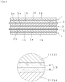
- Fig. 1 is a sectional view showing a lithium secondary battery using an electrolyte holder of the present invention and a partly enlarged view thereof.
- the porosity of an electrolyte holder to be used as a separator to have a sufficiently high porosity in conformity to the porosity of the surface of an active substances of its positive and negative electrodes. This is to facilitate the migration of lithium ions and improve the electrolytic solution holding performance of the electrolyte holder at an interface between the electrolytic solution and each electrode. Metallic lithium dendrite will precipitate on the surface of the negative electrode. The higher the porosity of the electrolyte holder is, the more easily the dendrite precipitates and grows, which makes it easy for a short circuit to occur.
- the electrolyte holder of the present invention has a high porosity as a whole and a multi-layer structure in which a fibrous layer having a lowporosity is disposed at the side of an anode to restrain the precipitation and growth of the metallic lithium dendrite on the surface of the negative electrode when the lithium secondary battery is charged and discharged at high current and particularly when the lithium secondary battery is charged at high current and thereby prevent a short circuit from occurring in the battery.
- the electrolyte holder of the present invention is used as the separator for the lithium secondary battery in which an organic electrolytic solution is permeated into an electrode group formed by winding the cathode and the anode or by laminating the cathode and the anode one upon another with the separator being interposed therebetween to repeatingly occlude and discharge lithium ions.
- Fig. 1 is a sectional view showing an example of the lithium secondary battery of the present invention and a partly enlarged view thereof.
- Fig. 1 particularly shows a sectional view of an electrode group formed by laminating the cathode, the anode, and the electrolyte holder one upon another. As shown in Fig.
- the lithium secondary battery of the present invention has the electrode group formed by laminating an anode 1 having an anode mixed agent layer 1b and a foil-shaped anode collector 1a and a cathode 2 having a cathode mixed agent layer 2b and a foil-shaped cathode collector 2a one upon another via an electrolyte holder 3 serving as the separator.
- the electrode group constructed by laminating the cathode, the anode, and the electrolyte holder one upon another the electrode group constructed by winding the anode and the cathode via the electrolyte holder is exemplified.
- the electrode group is immersed in the electrolytic solution inside a closed battery case (drawing is not shown).
- the electrolyte holder consists of a multi-layer structure having at least two fibrous layers.
- the fibrous layers are laminated one upon another in parallel with the cathode and anode.
- the layers (A, B) may be laminated one upon another by interposing another layer such as a film layer therebetween.
- Each fibrous layer consists of a hydrophilic fibrous material and has a porous portion (gap between fibers) capable of holding the organic electrolytic solution therein.
- the fibrous material consists of nonwoven cloth formed by using a fiber material which will be described later as a material therefor or consists of paper formed by using the fiber material.
- the porosities of the fibrous layers are different from each other.
- the organic electrolytic solution has a high affinity for the hydrophilic electrolyte holder. Therefore the electrolyte holder can be easily impregnated with the organic electrolytic solution and is capable of easily holding it.
- the film layer is added to the fibrous layers as necessary to improve the safety of the battery by preventing a short circuit and heat generation from occurring inside the battery, when the porosities of the fibrous layers are set high.
- a synthetic resin film consisting of polyolefin resin such as polyethylene resin and polypropylene resin are exemplified.
- the thickness of the entire electrolyte holder is 20 to 100 ⁇ m. It is possible to appropriately determine the thickness of each fibrous layer constructing the electrolyte holder within a range in which the entire thickness of the entire electrolyte holder falls within the above-described range. The thicknesses of the fibrous layers may be equal to one another or different from one another.
- the average porosity of the entire fibrous layer thereof is set to not less than 50%.
- the average porosity of the entire fibrous layer means an average value calculated from the porosity of each fibrous layer.
- the plane sizes of the fibrous layers are equal to each other, and the thicknesses of the fibrous layers can be appropriately determined.
- the average porosity ⁇ can be calculated based on the above-described calculation method.
- the porosity of each fibrous layer can be calculated as described below.
- the electrolyte holder is so constructed that the porosity of the fibrous layer disposed at the interface between the fibrous layer and the anode is set smaller than that of the fibrous layer disposed at the interface between the fibrous layer and the cathode .
- the description of "the porosity of the fibrous layer disposed at the interface between the fibrous layer and the anode is set smaller than that of the fibrous layer disposed at the interface between the fibrous layer and the cathode" means that when attention is paid to arbitrary two layers constructing the electrolyte holder, the two layers are separated into the layer forming the interface between it and the cathode and the layer forming the interface between it and the anode according to a positional relationship between the electrode plates and each fibrous layer.
- the porosity of the layer forming the interface between it and the anode is lower than that of the layer forming the interface between it and the cathode. That is, the porosity of the fibrous layer near to the anode is set low, whereas the porosity of the fibrous layer near to the cathode is set high.
- the porosity of each fibrous layer is so set that not less than 50% can be secured as the average porosity of the entire fibrous layer. Describing the specific range of the porosity of each fibrous layer, the porosity of a fibrous layer A which is adjacent to the anode and constructs the interface between the fibrous layer A and the anode is set to 40% to 80% and that of a fibrous layer B which is adjacent to the cathode and constructs the interface between the fibrous layer B and the cathode to 60% to 90%.
- the porosities of the fibrous layers A and B By setting the porosities of the fibrous layers A and B to the above-described range, it is possible to maintain the mobile state of the lithium ions at the interface between the fibrous layer B and the positive electrode and the interface between the fibrous layer A and the negative electrode while the battery is being charged and discharged.
- the porosity of the fibrous layer A exceeds 80%, there is a fear that the precipitation and growth of the dendrite cannot be restrained.
- the porosity of the fibrous layer A is less than 40%, the amount of the organic electrolytic solution to be retained thereby is smaller than that to be retained thereby when the porosity thereof is not less than 40%. Thus there is a fear that electrolyte shortage occurs in a short cycle life.
- the porosity of the fibrous layer B is high. But when the porosity thereof exceeds 90%, the fibrous layer B has a low tensile strength. Thereby the fibrous layer B cannot be practically used.
- the electrolyte holder retains a large amount of the organic electrolytic solution and thus the occurrence of the shortage of the organic electrolytic solution can be prevented to a higher extent.
- Both inorganic fibers and organic fibers are known in the art as a main material of the fibrous layers, provided that the inorganic and organic fibers have hydrophilic and electric insulation properties. It is possible to use non-hydrophilic fibers after subjecting the surfaces thereof to hydrophilic treatment of introducing oxygen and/or a sulfur-containing functional group (a sulfonic acid group, a sulfonate group, a sulfo-fluoride group, a carboxyl group, a carbonyl group) into the surfaces thereof, introducing graft-polymerized hydrophilic monomers thereinto or attaching a surface active agent to the surfaces thereof.
- a sulfur-containing functional group a sulfonic acid group, a sulfonate group, a sulfo-fluoride group, a carboxyl group, a carbonyl group
- Examples of the inorganic fibers known in the art include glass fibers, ceramic fibers, and the like.
- Examples of the organic fibers known in the art include natural fibers such as cellulose, regenerated fibers reproduced and refined from the natural fibers, and synthetic resin fibers.
- Examples of materials of the synthetic resin fibers include polyester resin such as polyethylene terephthalate, polybutylene terephthalate, and polyethylene naphthalate; polyolefin resin such as polyethylene, polypropylene; copolymers thereof; polyamide resin; acrylic resin; and vinyl resin. These fibers may be used singly or in combination of not less than two kinds.
- regenerated cellulose fibers derived from natural products are used in the present invention as the main material for the fibrous layer because these fibers are hydrophilic and heat-resistant without separately treating the surfaces thereof.
- Materials of the cellulose fibers are not limited to specific ones, but needle-leaf kraft pulp, broad-leaf kraft pulp, Manila hemp pulp, sisal hemp pulp, bamboo pulp, esparto pulp, and cotton pulp are listed.
- regenerated cellulose fibers regenerated cellulose fibers (polynosic rayon) having a high polymerization degree formed by using low acid solvent spinning and solvent spinning rayon formed by using an amine oxide based organic solvent are exemplified.
- the cellulose fibers are used after removing impurities therefrom by means of cleaning, dehydration or dust removal.
- these fibers are beaten with a beater to form a high-density fibrous layer.
- the fibrous layer has a high density, a high tensile strength, and a high ionic permeability.
- the beating degree JIS P 8121 is set to a range in which the porosity of the present invention is ensured. It is possible to use the beaten fibers and other fibers by mixing them with each other.
- the fibrous layer can be produced by using the above-described fibers as its main material with a paper machine such as a fourdrinier paper machine, a tanmo machine or a cylinder paper machine.
- a paper machine such as a fourdrinier paper machine, a tanmo machine or a cylinder paper machine.
- the fibrous layers are allowed to adhere to one another with high adhesion.
- the electrolyte holder To allow the structure of the electrolyte holder to restrain the precipitation and growth of the dendrite and be simple and have an excellent productivity, it is preferable to form the electrolyte holder as a two-layer structure consisting of the fibrous layer A constructing the interface between it and the anode and the fibrous layer B constructing the interface between it and the cathode (see Fig. 1 ) or as a three-layer structure having one synthetic resin film layer disposed between the fibrous layers A and B as necessary.
- the anode 1 consists of the foil-shaped anode collector 1a and the anode mixed agent layer 1b formed on both surfaces thereof.
- the anode mixed agent layer 1b is formed by kneading a main material, serving as an active substance, which is capable of occluding and discharging lithium ions, a binding agent, and a dispersion solvent to form a pasty mixture and thereafter applying the pasty mixture to both surfaces of the foil-shaped anode collector 1a.
- a copper foil is used owing to its electrochemical property, foil shape processability, and its cost.
- Examples of materials capable of occluding and discharging the lithium ions include a carbon material, a lithium-aluminum alloy, a silicon-based alloy or a tin-based lithium alloy, oxide mixtures thereof, and lithium titanate. Of these materials, it is preferable to use the carbon material because it has a small irreversible capacity. But in recent years, lithium titanate, silicon oxide, and a metallurgical silicon mixture have come to be used as materials having a high capacity.
- the electrolyte holder of the present invention can be used when any negative electrode active substance is used.
- the use of the electrolyte holder is especially effective when an active substance used occludes lithium ions at a lithium ion occlusion potential falling in a range in which the precipitation of the dendrite of the lithium ions occurs. That is, it is preferable to apply the electrolyte holder to the case in which the active substance which occludes the lithium ions at a potential lower than a lithium ion occlusion potential of 0.2V (vs. Li/Li + ).
- a carbon material is exemplified.
- the cathode 2 consists of the foil-shaped cathode collector 2a and the cathode mixed agent layer 2b formed on both surfaces thereof.
- the cathode mixed agent layer 2b is formed by kneading a main material, serving as an active substance, which consists of laminar or spinel-shaped lithium-containing metal oxide or solid solutions thereof, a lithium-containing metal phosphoric acid compound or a lithium-containing metal silicate, fluorides thereof or a lithium-containing compound, a binding agent, and a dispersion solvent to form a pasty mixture and thereafter applying the pasty mixture to both surfaces of the foil-shaped cathode collector 2a.
- a main material serving as an active substance, which consists of laminar or spinel-shaped lithium-containing metal oxide or solid solutions thereof, a lithium-containing metal phosphoric acid compound or a lithium-containing metal silicate, fluorides thereof or a lithium-containing compound, a binding agent, and a dispersion solvent to form a pasty mixture and
- LiCoO 2 Li(Ni/Co/Mn)O 2 , and LiMn 2 O 4 are listed.
- LiFePO 4 LiCoPO 4 , and LiMnPO 4 are listed.
- LiFeSiO 4 LiFeSiO 4 is exemplified.
- fluorides thereof Li 2 FePO 4 ⁇ F is exemplified.
- LiTi 2 (PO 4 ) 3 , and LiFeO 2 are listed. Of these materials, it is preferable to use LiCoO 2 , Li(Ni/Co/Mn)O 2 , LiMn 2 O 4 , and LiFePO 4 are listed.
- the cathode collector it is preferable to set the density of the cathode mixed agent layer 1.8 to 3.6g/cc. Except for except the anode collector, it is preferable to set the density of the anode mixed agent layer to 1.2 to 1.7g/cc.
- the densities of both the positive and anode mixed agent layers are out of the above-described range, i.e., when the densities thereof are lower than the lower limit, the adhesiveness between the mixed agent consisting of the active substance and the current collector deteriorates. Thus there is a fear that the cyclic performance deteriorates.
- the porosity of the anode mixed agent layer is higher than that of the cathode mixed agent layer.
- the porosity of the fibrous layer forming the interface between it and the negative electrode is set low and yet a high porosity (not less than 50%) is secured for the entire fibrous layer.
- the electrolyte holder of the present invention is applicable to arbitrary positive and negative electrode materials other than the above-described ones.
- the battery As an effective combination of the positive and negative electrode materials which allows the output characteristic of the lithium secondary battery to be improved, the battery to have a long life, and in addition the battery to have a high-capacity material as a small and light battery, to be mounted on vehicles, the development of which will be demanded in the future, the following combination is devised in the present invention. That is, to form the cathode mixed agent layer of the cathode, olivine type LiPePO 4 formed by coating a powder surface having a long life, a low cost, and a high safety with conductive carbon is used as a main material thereof.
- Acetylene black and carbon nanotube both of which are conductive carbon are bonded to the main material.
- a carbon material consisting of graphite powder, coated with conductive carbon, to which acetylene black and carbon nanotube both of which are conductive carbon are bonded By using the electrolyte holder of the present invention as the separator between the positive electrode material combined with the negative electrode material, it is possible to restrain the precipitation and growth of the dendrite of the metallic lithium and prevent a short circuit from occurring inside the battery.
- the organic electrolytic solution in which the above-described electrode group is immersed it is preferable to use a nonaqueous electrolytic solution containing lithium salts or ionic conduction polymers.
- polar organic solvents are exemplified.
- the polar organic solvents include ethylene carbonate (EC), propylene carbonate (PC), diethyl carbonate (DEC), dimethyl carbonate (DMC), and methyl ethyl carbonate (MEC) . These polar organic solvents have affinity for the hydrophilic electrolyte holder.
- lithium salts soluble in the above-described solvents examples include lithium hexafluorophosphate (LiPF 6 ), lithium tetrafluoroborate ((LiBF 4 ), and lithium trifluoromethanesulfonate (LiSO 3 CF 3 ).
- the lithium secondary battery having the construction shown in Fig. 1 may be so constructed that a plurality of holes penetrating through the foil-shaped anode collector 1a and the foil-shaped cathode collector 2a is formed and that the peripheries of the holes are projected toward at least one surface of each of the foil-shaped anode and cathode collectors.
- the cathode of the lithium secondary battery was produced by a method described below.
- Olivine type lithium iron phosphate the surface of which was coated with conductive carbon whose secondary particle diameter was 2 to 3 ⁇ m was used as a positive electrode active substance .
- N-methylpyrrolidone was added to the mixture of the positive electrode active substance, the conductive agent, and the binding agent.
- the components were kneaded to prepare a cathode mixed agent (positive electrode slurry).
- An aluminum foil having a thickness of 20 ⁇ m and a width of 150mm was prepared.
- the positive electrode slurry was applied to both surfaces of the aluminum foil and dried. Thereafter the aluminum foil was pressed and cut to obtain the cathode for the lithium secondary battery.
- the total thickness of the positive electrode obtained by applying the positive electrode slurry to both surfaces of the aluminum foil, drying the positive electrode slurry, and pressing the aluminum foil was 160 ⁇ m.
- Acetylene black and carbon nanotube serving as a conductive agent were added to 90 parts by weight of a carbon material (soft carbon), the surface of which was coated with carbon to obtain composite powders.
- a binding agent five parts by weight of vinylidene polyfluoride was added to 95 parts by weight of the composite powders as a binding agent.
- N-methylpyrrolidone was added to the mixture consisting of the composite powders and the binding agent.
- the components were kneaded to prepare an anode mixed agent (negative electrode slurry).
- a copper foil having a thickness of 10 ⁇ m and a width of 150mm was prepared.
- the negative electrode slurry was applied to the copper foil and dried. Thereafter the copper foil was pressed and cut to obtain the anode for the lithium secondary battery.
- the total thickness of the negative electrode obtained by applying the negative electrode slurry to both surfaces of the copper foil, drying the slurry, and pressing the copper foil was 120 ⁇ m.
- a pouch type battery of 3.4V-500 mAh was produced experimentally.
- two fibrous layers, made of cellulose fibers were pasted to each other with an on-machine .
- One fibrous layer forming the interface between it and the positive electrode had a porosity of 80% and a thickness of 40 ⁇ m.
- the other fibrous layer forming the interface between it and the negative electrode had a porosity of 60% and a thickness of 40 ⁇ m.
- the two fibrous layers were bonded to each other by using an on-machine.
- the obtained electrolyte holder had an average porosity of 70% and a total thickness of 80 ⁇ m.
- cellulose fibers solvent spun regenerated cellulose fiber was used. After the cellulose fibers were beaten to a predetermined beating degree, two-layer paper was formed by using a fourdrinier-cylinder combination paper machine. The fibrous layer of the two-layer paper formed by using a fourdrinier paper machine had a porosity of 60%. The fibrous layer of the two-layer paper formed by using a cylinder paper machine had a porosity of 80%.
- a battery was experimentally produced by using the cathode and anode of the example 1 and a one-layer polyethylene film separator serving as electrolyte holder.
- the film separator had a thickness of 80 ⁇ m and a porosity of 40%.
- a battery similar to that of the comparative example 1 was experimentally produced by using the cathode and anode of the example 1 and a one-layer separator, consisting of cellulose fibers, which served the electrolyte holder.
- the separator had a thickness of 80 ⁇ m and a porosity of 45%.
- a battery similar to that of the comparative example 1 was experimentally produced by using the cathode and anode of the example 1 and a two-layer separator, consisting of cellulose fibers, which served as the electrolyte holder and had an average porosity of 40%.
- One fibrous layer forming the interface between it and the positive electrode had a porosity of 50% and a thickness of 40 ⁇ m.
- the other fibrous layer forming the interface between it and the negative electrode had a porosity of 30% and a thickness of 40 ⁇ m.
- a battery similar to that of the comparative example 1 was experimentally produced by using the cathode and anode of the example 1 and a two-layer separator, consisting of cellulose fibers, which served as the electrolyte holder and had an average porosity of 70%.
- One fibrous layer forming the interface between it and the positive electrode had a porosity of 80% and a thickness of 30 ⁇ m.
- the other fibrous layer forming the interface between it and the negative electrode had a porosity of 60% and a thickness of 30 ⁇ m.
- one polyolefin film layer was interposed between the two fibrous layers and pasted thereto.
- the obtained separator or electrolyte holder had a total thickness of 80 ⁇ m.
- the discharge capacity of each of five kinds of the batteries of the example 1 and 2 and the comparative examples 1 through 3 was measured by flowing constant currents of 0.5A and 15A therethrough until the voltage thereof dropped to 2.0V to calculate the ratio of the discharge capacity of each battery when it was discharged at 15A to the discharge capacity thereof when it was discharged at 0.5A. After each battery was charged at 50%, it was discharged at 0.1A, 0.5A, 1A, 1.5A, and 2.5A for 10 seconds from the time when the circuit was opened to measure the voltage thereof after the lapse of 10 seconds.
- the slopes of the lines were found by using a least-squares method to obtain DC resistance values when the batteries were charged at 50%.
- the obtained values of the slopes of the lines, namely, the obtained DC resistance values were compared with one another.
- the positive electrode consisted of LiFePO 4 .
- ignition did not occur.
- smoke emission partly occurred owing to the precipitation of the dendrite of the metallic lithium at the negative electrode.
- any of the fibrous electrolyte holders no ignition or smoke emission occurred. It has been found that heat generation caused by the precipitation of the dendrite and by the decomposition of the electrolytic solution was restrained to a higher extent in the fibrous electrolyte holders of the examples of the present invention than in the electrolyte holder of the comparative example 2 having a low porosity.
- the film restrained the precipitation of the dendrite and heat generation to a higher extent. It is conceivable that the fibrous electrolyte holder allowed a larger amount of the electrolytic solution to permeate thereinto than the separator made of the film and thus the electrolytic solution to have an improved heat conduction, which restrained heat generation.
- the lithium secondary battery using the electrolyte holder of the present invention can be repeatingly charged and discharged at high current and has a cycle life of 10000 to 20000 and a service life of 10 to 20 years and thus can be used in industrial applications.
- the lithium secondary battery of the present invention can be mounted on vehicles and used as a stationary type.
Description
- The present invention relates to a holder for holding an electrolyte for use in a lithium secondary battery and the lithium secondary battery using the holder.
- The lithium secondary battery formed by using a material capable of absorbing and discharging lithium ions is capable of restraining precipitation of dendrite to a higher extent than a lithium battery in which the negative electrode is formed by using metallic lithium. Therefore the lithium secondary battery has been supplied to the market as a battery having enhanced safety. In recent years, the development of the lithium secondary battery is advanced for industrial use including a case in which the lithium secondary battery is mounted on a vehicle and a case in which it is used as a stationary power source. It is a big problem to allow the lithium secondary battery to have a high output (in charging and discharging it at high current) and a long life, even though it is repeatingly charged and discharged at high current.
- To overcome this problem, there have been improvements including an increase in the capacity of a positive electrode material composed of a lithium metal oxide and in the capacity of the negative electrode material composed of a carbon-based material, a material containing a titanium oxide or an alloy-based material to allow high current to flow through the lithium secondary battery. The diameters of active substance particles are decreased to increase the specific surface area of the active substance and in addition the electrodes are so designed as to increase the areas thereof so that the current density load of the lithium secondary battery can be decreased.
- The above-described devices have improved the performance of the lithium secondary battery in allowing the lithium secondary battery to be charged and discharged at high current, but were insufficient as a measure for prolonging the life of the lithium secondary battery. Therefore the substitution mixing ratio of metal elements of lithium metal oxides used to form the positive electrode and substitution of doped metals have been investigated. There has been proposed an additive devised to prevent a resistance film from being generated by the decomposition of an electrolytic solution at the negative electrode composed of a carbon-based material. To improve the performance of the negative electrode composed of an alloy-based material having a semiconductor property, there has been also proposed an alloy composition, the addition of a conductive material, and a binding agent devised to restrain the volume expansion of an alloy. For example, the electrode of the secondary battery composed of the active substance powders, the electrode material formed from the carbon material and attaching to the surface of the active substance powders, and the fibrous conductive material combined with the conductive material is known (see
patent document 1 =JP-A-20080277128 - As a separator to be interposed between the cathode and the anode, a polyethylene film having a porosity of about 40% is mainly used. In addition, to improve high-temperature storage performance and output characteristics in the range from high temperatures to low temperatures, there is proposed the separator consisting of cellulose fibers heat-resistant and excellent in impregnation performance for a nonaqueous electrolyte (
patent document 2 =JP-A-2009081048
JP-A-2007018861
JP-A-2011233354 center part 2. - Although the above-described proposed means as disclosed in the
patent document 1 are capable of increasing the cycle life up to 2000 to 3000 cycle level from hundreds of cycles, the means are insufficient for increasing the cycle life to 10 to 20 years and 10000 to 20000 cycles in the case where the lithium secondary battery is used to mount it on vehicles or stationary. In a method of relaxing the volume expansion of the alloy by increasing the adhesive force of the binding agent of the alloy-based negative electrode, there is an increase in the use amount of the binding agent when it is used as the technique of making the active substance consisting of the alloy fine and preventing the active substance from separating from the electricity collection foil. Thus a produced battery does not meet a designed capacity, and the cost increases. Thus it is difficult for the proposed means to satisfy the demanded performance to such an extent that batteries can be used for industrial application. - Of proposals hitherto made, many of them is related to the main material of the secondary battery. A certain level of effect can be expected. But examining the cause of a decrease of the life of battery and failure thereof, in many cases, it has been found that the decrease of the life of the battery is caused by a minute short circuit between electrodes and solution shortage inside the electrodes rather than the deterioration of the active substance which is the main material of the electrodes.
- In the proposal disclosed in the
patent document 2, the cellulose fibers excellent in its impregnation property are utilized as the separator. The separator consisting of the cellulose easily holds the electrolytic solution as compared with the separator consisting of the polyethylene film. But the separator has a single-layer construction having a constant porosity, the porosity thereof cannot be adjusted at the interface between the separator and the positive and negative electrodes in conformity to the properties of the positive and negative electrodes, and the electrolytic solution is liable to migrate to a battery can. Thereby there is a case in which solution shortage cannot be sufficiently prevented. The art disclosed in thepatent document 2 assumes that the lithium titanium oxide, having a lithium ion occlusion potential of not less than 0.2V (vs. Li/Li+), which is capable of preventing the precipitation of dendrite is used as the negative electrode active substance. Thus it is difficult to apply the art of thepatent document 2 to a case in which a negative electrode active substance such as a carbon material is used. - The present invention has been made to cope with the above-described problems. It is an object of the present invention to provide an electrolyte holder for a lithium secondary battery capable of holding an electrolytic solution inside electrodes or at an interface between a separator and each of the electrodes, preventing solution shortage inside the electrodes, and restraining dendrite from precipitating and growing and also provide the lithium secondary battery, using the electrolyte holder, which is capable of achieving a cycle life to such an extent that the lithium secondary battery can be used for industrial application.
- The invention provides and electrolyte holder as claimed in
claim 1 and a lithium secondary battery including the electrolyte holder as claimed in claim 9. - A porosity of a fibrous layer A constructing an interface between the fibrous layer A and the anode is set to 50% to 60%, and a porosity of a fibrous layer B constructing an interface between the fibrous layer B and the cathode is set to 70% to 80%. The electrolyte holder has (1) a two-layer structure consisting of the fibrous layer A and the fibrous layer B or (2) a three-layer structure consisting of the fibrous layer A, the fibrous layer B, and a film layer, made of synthetic resin, which is disposed between the fibrous layer A and the fibrous layer B.
- The fibrous layers are formed by using beaten regenerated fibers as a main material thereof. An active substance for use in the anode is a carbon material.
- The electrolyte holder of the present invention for the lithium secondary battery has a multi-layer structure composed of at least two hydrophilic fibrous layers having different porosities. The average porosity of the entire fibrous layer is set to not less than 50% and is thus higher than that of conventional film separators. Therefore the electrolyte holder of the present invention is capable of holding a larger amount of the electrolytic solution than the conventional film separators. In addition, the electrolyte holder of the present invention has the multi-layer structure having fibrous layers composed of different porosities. Therefore according to the properties of the active substance surfaces of the electrode plates, it is possible to appropriately set the porosities of the fibrous layers adjacent to the electrode plates. By forming the fibrous layers having the porosities according to the properties of the active substance surfaces, lithium ions are capable of easily migrating at the interface between the positive electrode and one fibrous layer and the interface between the negative electrode and the other fibrous layer, while the battery is being charged and discharged, and thus it is possible to maintain the migration state of the lithium ions at the above-described interfaces. Therefore the battery can be charged and discharged at high current, the retention amount of the electrolytic solution is unlikely to change at the above-described interfaces, the electrolytic solution little moves from the electrolyte holder to the wall of a battery can. Thus it is possible to prevent the occurrence of electrolyte shortage inside the electrodes and the above-described interfaces. Furthermore because the electrolyte holder is so constructed that the entire electrolyte holder has a high porosity and that the fibrous layer having a low porosity is disposed at the side of the anode, it is possible to restrain the metallic lithium dendrite from precipitating and growing on the surface of the negative electrode, while the battery is being charged and discharged at high current. Thereby by using the electrolyte holder as the separator, it is possible to greatly reduce the electric resistances of electrode materials, charge and discharge the battery at high current, and improve the cycle life characteristics.
-
Fig. 1 is a sectional view showing a lithium secondary battery using an electrolyte holder of the present invention and a partly enlarged view thereof. - In the lithium secondary battery, it is preferable to allow the porosity of an electrolyte holder to be used as a separator to have a sufficiently high porosity in conformity to the porosity of the surface of an active substances of its positive and negative electrodes. This is to facilitate the migration of lithium ions and improve the electrolytic solution holding performance of the electrolyte holder at an interface between the electrolytic solution and each electrode. Metallic lithium dendrite will precipitate on the surface of the negative electrode. The higher the porosity of the electrolyte holder is, the more easily the dendrite precipitates and grows, which makes it easy for a short circuit to occur. In consideration of this problem, the electrolyte holder of the present invention has a high porosity as a whole and a multi-layer structure in which a fibrous layer having a lowporosity is disposed at the side of an anode to restrain the precipitation and growth of the metallic lithium dendrite on the surface of the negative electrode when the lithium secondary battery is charged and discharged at high current and particularly when the lithium secondary battery is charged at high current and thereby prevent a short circuit from occurring in the battery.
- The electrolyte holder of the present invention is used as the separator for the lithium secondary battery in which an organic electrolytic solution is permeated into an electrode group formed by winding the cathode and the anode or by laminating the cathode and the anode one upon another with the separator being interposed therebetween to repeatingly occlude and discharge lithium ions.
- An example of the lithium secondary battery using the electrolyte holder of the present invention therefor is described below with reference to the drawings.
Fig. 1 is a sectional view showing an example of the lithium secondary battery of the present invention and a partly enlarged view thereof.Fig. 1 particularly shows a sectional view of an electrode group formed by laminating the cathode, the anode, and the electrolyte holder one upon another. As shown inFig. 1 , the lithium secondary battery of the present invention has the electrode group formed by laminating ananode 1 having an anode mixedagent layer 1b and a foil-shaped anode collector 1a and acathode 2 having a cathode mixed agent layer 2b and a foil-shaped cathode collector 2a one upon another via anelectrolyte holder 3 serving as the separator. In addition to the electrode group constructed by laminating the cathode, the anode, and the electrolyte holder one upon another, the electrode group constructed by winding the anode and the cathode via the electrolyte holder is exemplified. The electrode group is immersed in the electrolytic solution inside a closed battery case (drawing is not shown). - Initially the
electrolyte holder 3 is described in detail below. - The electrolyte holder consists of a multi-layer structure having at least two fibrous layers. The fibrous layers are laminated one upon another in parallel with the cathode and anode. As shown in
Fig. 1 , as lamination methods, in addition to lamination of layers (A, B) by directly contacting the layers (A, B) each other, the layers (A, B) may be laminated one upon another by interposing another layer such as a film layer therebetween. Each fibrous layer consists of a hydrophilic fibrous material and has a porous portion (gap between fibers) capable of holding the organic electrolytic solution therein. The fibrous material consists of nonwoven cloth formed by using a fiber material which will be described later as a material therefor or consists of paper formed by using the fiber material. The porosities of the fibrous layers are different from each other. By adopting the multi-layer structure consisting of a plurality of fibrous layers having different porosities, it is possible to appropriately set the porosities of the fibrous layers adjacent to the electrode plates according to the properties (configuration and porosity) of the surface of the active substance of each electrode plate and maintain amobile state of lithium ions on the interface between one fibrous layer and the positive electrode and the interface between the other fibrous layer and the negative electrode while the battery is being charged and discharged. - Because a polar organic solvent is used as the solvent of the organic electrolytic solution of the lithium secondary battery, the organic electrolytic solution has a high affinity for the hydrophilic electrolyte holder. Therefore the electrolyte holder can be easily impregnated with the organic electrolytic solution and is capable of easily holding it.
- The film layer is added to the fibrous layers as necessary to improve the safety of the battery by preventing a short circuit and heat generation from occurring inside the battery, when the porosities of the fibrous layers are set high. As the film layer which can be used in the present invention, a synthetic resin film consisting of polyolefin resin such as polyethylene resin and polypropylene resin are exemplified.
- The thickness of the entire electrolyte holder is 20 to 100µm. It is possible to appropriately determine the thickness of each fibrous layer constructing the electrolyte holder within a range in which the entire thickness of the entire electrolyte holder falls within the above-described range. The thicknesses of the fibrous layers may be equal to one another or different from one another.
- In the electrolyte holder, the average porosity of the entire fibrous layer thereof is set to not less than 50%. By setting the porosity thereof to not less than 50%, it is possible to hold a large amount of the organic electrolytic solution at the gap between fibers of the holder and prevent the occurrence of the shortage of the organic electrolytic solution. "The average porosity of the entire fibrous layer" means an average value calculated from the porosity of each fibrous layer. The plane sizes of the fibrous layers are equal to each other, and the thicknesses of the fibrous layers can be appropriately determined. Thus in the case where the electrolyte holder consists of a first layer (porosity: X, thickness: a) and a second layer (porosity: Y, thickness: b), an average porosity α can be calculated based on the following equation:

- In the case where the thickness of the first layer is equal to that of the second layer, the average porosity α is as follows: α = (X+Y) /2. In the case where the electrolyte holder consists of not less than three layers, the average porosity α can be calculated based on the above-described calculation method.
- The porosity of each fibrous layer can be calculated as described below. A certain volume (actual volume: V, actual weight: W) is taken out of each fibrous layer to set it as a specimen. Supposing that a true density of the fiber forming the fibrous layer is A, the occupation volume of the fiber of the specimen is W/A. By subtracting the occupation volume W/A of the fiber from the actual volume of V, the volume of pores is found according to calculations. Therefore the porosity (%) = 100 × (V-W/A)/V. This can be expressed as 100 × (1 - (W/V)/A). Because W/V is an apparent density of the specimen, the porosity can be calculated as: the porosity (%) = 100 × (1 - apparent density/true density of fiber).
- The electrolyte holder is so constructed that the porosity of the fibrous layer disposed at the interface between the fibrous layer and the anode is set smaller than that of the fibrous layer disposed at the interface between the fibrous layer and the cathode . The description of "the porosity of the fibrous layer disposed at the interface between the fibrous layer and the anode is set smaller than that of the fibrous layer disposed at the interface between the fibrous layer and the cathode" means that when attention is paid to arbitrary two layers constructing the electrolyte holder, the two layers are separated into the layer forming the interface between it and the cathode and the layer forming the interface between it and the anode according to a positional relationship between the electrode plates and each fibrous layer. In this case, the porosity of the layer forming the interface between it and the anode is lower than that of the layer forming the interface between it and the cathode. That is, the porosity of the fibrous layer near to the anode is set low, whereas the porosity of the fibrous layer near to the cathode is set high. By disposing the fibrous layer having a low porosity at the side of the anode, it is possible to restrain the dendrite of the metallic lithium from precipitating and growing on the surface of the negative electrode while the battery is being charged and discharged at high current and especially when the battery is charged at high current. Consequently it is possible to prevent a short circuit from occurring inside the battery.
- The porosity of each fibrous layer is so set that not less than 50% can be secured as the average porosity of the entire fibrous layer. Describing the specific range of the porosity of each fibrous layer, the porosity of a fibrous layer A which is adjacent to the anode and constructs the interface between the fibrous layer A and the anode is set to 40% to 80% and that of a fibrous layer B which is adjacent to the cathode and constructs the interface between the fibrous layer B and the cathode to 60% to 90%. By setting the porosities of the fibrous layers A and B to the above-described range, it is possible to maintain the mobile state of the lithium ions at the interface between the fibrous layer B and the positive electrode and the interface between the fibrous layer A and the negative electrode while the battery is being charged and discharged. When the porosity of the fibrous layer A exceeds 80%, there is a fear that the precipitation and growth of the dendrite cannot be restrained. When the porosity of the fibrous layer A is less than 40%, the amount of the organic electrolytic solution to be retained thereby is smaller than that to be retained thereby when the porosity thereof is not less than 40%. Thus there is a fear that electrolyte shortage occurs in a short cycle life. It is preferable that the porosity of the fibrous layer B is high. But when the porosity thereof exceeds 90%, the fibrous layer B has a low tensile strength. Thereby the fibrous layer B cannot be practically used.
- It is more favorable to set the porosity of the fibrous layer A to 50% to 60% and that of the fibrous layer B to 70% to 80%. By setting the porosity of the fibrous layer A whose porosity should be set smallest to not less than 50%, namely, by setting porosities of all the fibrous layers to not less than 50%, the electrolyte holder retains a large amount of the organic electrolytic solution and thus the occurrence of the shortage of the organic electrolytic solution can be prevented to a higher extent.
- Both inorganic fibers and organic fibers are known in the art as a main material of the fibrous layers, provided that the inorganic and organic fibers have hydrophilic and electric insulation properties. It is possible to use non-hydrophilic fibers after subjecting the surfaces thereof to hydrophilic treatment of introducing oxygen and/or a sulfur-containing functional group (a sulfonic acid group, a sulfonate group, a sulfo-fluoride group, a carboxyl group, a carbonyl group) into the surfaces thereof, introducing graft-polymerized hydrophilic monomers thereinto or attaching a surface active agent to the surfaces thereof.
- Examples of the inorganic fibers known in the art include glass fibers, ceramic fibers, and the like. Examples of the organic fibers known in the art include natural fibers such as cellulose, regenerated fibers reproduced and refined from the natural fibers, and synthetic resin fibers. Examples of materials of the synthetic resin fibers include polyester resin such as polyethylene terephthalate, polybutylene terephthalate, and polyethylene naphthalate; polyolefin resin such as polyethylene, polypropylene; copolymers thereof; polyamide resin; acrylic resin; and vinyl resin. These fibers may be used singly or in combination of not less than two kinds.
- Of these materials, regenerated cellulose fibers derived from natural products are used in the present invention as the main material for the fibrous layer because these fibers are hydrophilic and heat-resistant without separately treating the surfaces thereof. Materials of the cellulose fibers are not limited to specific ones, but needle-leaf kraft pulp, broad-leaf kraft pulp, Manila hemp pulp, sisal hemp pulp, bamboo pulp, esparto pulp, and cotton pulp are listed. As the regenerated cellulose fibers, regenerated cellulose fibers (polynosic rayon) having a high polymerization degree formed by using low acid solvent spinning and solvent spinning rayon formed by using an amine oxide based organic solvent are exemplified. The cellulose fibers are used after removing impurities therefrom by means of cleaning, dehydration or dust removal.
- To prevent the occurrence of a short circuit, these fibers are beaten with a beater to form a high-density fibrous layer. By beating the fibers, the fibrous layer has a high density, a high tensile strength, and a high ionic permeability. When the density of the fibrous layer is too high, the gap between fibers decreases and thus a predetermined porosity cannot be maintained. Therefore the beating degree (JIS P 8121) is set to a range in which the porosity of the present invention is ensured. It is possible to use the beaten fibers and other fibers by mixing them with each other.
- The fibrous layer can be produced by using the above-described fibers as its main material with a paper machine such as a fourdrinier paper machine, a tanmo machine or a cylinder paper machine. In addition, by laminating fibrous layers having different porosities one upon another with a fourdrinier-cylinder combination paper machine composed of the fourdrinier paper machine combined with the cylinder paper machine, the fibrous layers are allowed to adhere to one another with high adhesion.
- To allow the structure of the electrolyte holder to restrain the precipitation and growth of the dendrite and be simple and have an excellent productivity, it is preferable to form the electrolyte holder as a two-layer structure consisting of the fibrous layer A constructing the interface between it and the anode and the fibrous layer B constructing the interface between it and the cathode (see
Fig. 1 ) or as a three-layer structure having one synthetic resin film layer disposed between the fibrous layers A and B as necessary. - Structures of the electrodes other than that of the
electrolyte holder 3 are described in detail below. - The
anode 1 consists of the foil-shaped anode collector 1a and the anodemixed agent layer 1b formed on both surfaces thereof. The anodemixed agent layer 1b is formed by kneading a main material, serving as an active substance, which is capable of occluding and discharging lithium ions, a binding agent, and a dispersion solvent to form a pasty mixture and thereafter applying the pasty mixture to both surfaces of the foil-shaped anode collector 1a. As the foil-shaped anode collector 1a, a copper foil is used owing to its electrochemical property, foil shape processability, and its cost. - Examples of materials capable of occluding and discharging the lithium ions include a carbon material, a lithium-aluminum alloy, a silicon-based alloy or a tin-based lithium alloy, oxide mixtures thereof, and lithium titanate. Of these materials, it is preferable to use the carbon material because it has a small irreversible capacity. But in recent years, lithium titanate, silicon oxide, and a metallurgical silicon mixture have come to be used as materials having a high capacity.
- The electrolyte holder of the present invention can be used when any negative electrode active substance is used. The use of the electrolyte holder is especially effective when an active substance used occludes lithium ions at a lithium ion occlusion potential falling in a range in which the precipitation of the dendrite of the lithium ions occurs. That is, it is preferable to apply the electrolyte holder to the case in which the active substance which occludes the lithium ions at a potential lower than a lithium ion occlusion potential of 0.2V (vs. Li/Li+). As such a negative electrode active substance, a carbon material is exemplified.
- The
cathode 2 consists of the foil-shaped cathode collector 2a and the cathode mixed agent layer 2b formed on both surfaces thereof. The cathode mixed agent layer 2b is formed by kneading a main material, serving as an active substance, which consists of laminar or spinel-shaped lithium-containing metal oxide or solid solutions thereof, a lithium-containing metal phosphoric acid compound or a lithium-containing metal silicate, fluorides thereof or a lithium-containing compound, a binding agent, and a dispersion solvent to form a pasty mixture and thereafter applying the pasty mixture to both surfaces of the foil-shaped cathode collector 2a. As the foil-shaped cathode collector 2a, an aluminum foil is used owing to its performance. - As the laminar or spinel-shaped lithium-containing metal oxide, LiCoO2, Li(Ni/Co/Mn)O2, and LiMn2O4 are listed. As the solid solutions thereof, Li2MnO3-LiMO2(M = Ni, Co, Mn) . As the lithium-containing metal phosphoric acid compound, LiFePO4, LiCoPO4, and LiMnPO4 are listed. As the lithium-containing metal silicate, LiFeSiO4 is exemplified. As the fluorides thereof, Li2FePO4·F is exemplified. As the lithium-containing compound, LiTi2(PO4)3, and LiFeO2 are listed. Of these materials, it is preferable to use LiCoO2, Li(Ni/Co/Mn)O2, LiMn2O4, and LiFePO4 are listed.
- Except for the cathode collector, it is preferable to set the density of the cathode mixed agent layer 1.8 to 3.6g/cc. Except for except the anode collector, it is preferable to set the density of the anode mixed agent layer to 1.2 to 1.7g/cc. When the densities of both the positive and anode mixed agent layers are out of the above-described range, i.e., when the densities thereof are lower than the lower limit, the adhesiveness between the mixed agent consisting of the active substance and the current collector deteriorates. Thus there is a fear that the cyclic performance deteriorates. When the densities thereof are higher than the upper limit, the porousness of each electrode plate is not secured, and the diffusibility of the electrolytic solution is restrained. As a result, there is a fear that the performance of the battery deteriorates when the battery is charged and discharged at high current. In the case where the density of the cathode mixed agent layer and that of the anode mixed agent layer are set in the above-described range, the porosity of the anode mixed agent layer is higher than that of the cathode mixed agent layer. Thus in the electrolyte holder, it is preferable to set the porosity of the fibrous layer forming the interface between it and the negative electrode higher than that of the fibrous layer forming the interface between it and the positive electrode. In the present invention, to restrain the precipitation and growth of the dendrite of the metallic lithium, the porosity of the fibrous layer forming the interface between it and the negative electrode is set low and yet a high porosity (not less than 50%) is secured for the entire fibrous layer.
- The electrolyte holder of the present invention is applicable to arbitrary positive and negative electrode materials other than the above-described ones. As an effective combination of the positive and negative electrode materials which allows the output characteristic of the lithium secondary battery to be improved, the battery to have a long life, and in addition the battery to have a high-capacity material as a small and light battery, to be mounted on vehicles, the development of which will be demanded in the future, the following combination is devised in the present invention. That is, to form the cathode mixed agent layer of the cathode, olivine type LiPePO4 formed by coating a powder surface having a long life, a low cost, and a high safety with conductive carbon is used as a main material thereof. Acetylene black and carbon nanotube both of which are conductive carbon are bonded to the main material. To form the anode mixed agent layer opposed to the cathode, in consideration of a high capacity, a high regeneration, and a long life, it is most favorable to use a carbon material consisting of graphite powder, coated with conductive carbon, to which acetylene black and carbon nanotube both of which are conductive carbon are bonded. By using the electrolyte holder of the present invention as the separator between the positive electrode material combined with the negative electrode material, it is possible to restrain the precipitation and growth of the dendrite of the metallic lithium and prevent a short circuit from occurring inside the battery.
- In the lithium secondary battery, as the organic electrolytic solution in which the above-described electrode group is immersed, it is preferable to use a nonaqueous electrolytic solution containing lithium salts or ionic conduction polymers.
- As a nonaqueous solvent of the nonaqueous electrolytic solution containing the lithium salts, polar organic solvents are exemplified. Examples of the polar organic solvents include ethylene carbonate (EC), propylene carbonate (PC), diethyl carbonate (DEC), dimethyl carbonate (DMC), and methyl ethyl carbonate (MEC) . These polar organic solvents have affinity for the hydrophilic electrolyte holder.
- Examples of the lithium salts soluble in the above-described solvents include lithium hexafluorophosphate (LiPF6), lithium tetrafluoroborate ((LiBF4), and lithium trifluoromethanesulfonate (LiSO3CF3).
- In addition, the lithium secondary battery having the construction shown in
Fig. 1 may be so constructed that a plurality of holes penetrating through the foil-shaped anode collector 1a and the foil-shaped cathode collector 2a is formed and that the peripheries of the holes are projected toward at least one surface of each of the foil-shaped anode and cathode collectors. - The cathode of the lithium secondary battery was produced by a method described below.
- Olivine type lithium iron phosphate, the surface of which was coated with conductive carbon whose secondary particle diameter was 2 to 3µm was used as a positive electrode active substance . Eight parts by weight of a conductive agent consisting of a mixture of conductive carbon and conductive carbon composite and six parts by weight of a binding agent consisting of vinylidene polyfluoride were added to 86 parts by weight of the above-described active substance. As a dispersion solvent, N-methylpyrrolidone was added to the mixture of the positive electrode active substance, the conductive agent, and the binding agent. The components were kneaded to prepare a cathode mixed agent (positive electrode slurry). An aluminum foil having a thickness of 20µm and a width of 150mm was prepared. The positive electrode slurry was applied to both surfaces of the aluminum foil and dried. Thereafter the aluminum foil was pressed and cut to obtain the cathode for the lithium secondary battery. The total thickness of the positive electrode obtained by applying the positive electrode slurry to both surfaces of the aluminum foil, drying the positive electrode slurry, and pressing the aluminum foil was 160µm.
- Thereafter an anode for the lithium secondary battery was produced by a method described below.
- Acetylene black and carbon nanotube serving as a conductive agent were added to 90 parts by weight of a carbon material (soft carbon), the surface of which was coated with carbon to obtain composite powders. As a binding agent, five parts by weight of vinylidene polyfluoride was added to 95 parts by weight of the composite powders as a binding agent. Thereafter as a dispersion solvent, N-methylpyrrolidone was added to the mixture consisting of the composite powders and the binding agent. The components were kneaded to prepare an anode mixed agent (negative electrode slurry). A copper foil having a thickness of 10µm and a width of 150mm was prepared. The negative electrode slurry was applied to the copper foil and dried. Thereafter the copper foil was pressed and cut to obtain the anode for the lithium secondary battery. The total thickness of the negative electrode obtained by applying the negative electrode slurry to both surfaces of the copper foil, drying the slurry, and pressing the copper foil was 120µm.
- By using the cathode and anode, a pouch type battery of 3.4V-500 mAh was produced experimentally. As a separator and an electrolyte holder interposed between the cathode and anode, two fibrous layers, made of cellulose fibers, were pasted to each other with an on-machine . One fibrous layer forming the interface between it and the positive electrode had a porosity of 80% and a thickness of 40µm. The other fibrous layer forming the interface between it and the negative electrode had a porosity of 60% and a thickness of 40µm. The two fibrous layers were bonded to each other by using an on-machine. Thus the obtained electrolyte holder had an average porosity of 70% and a total thickness of 80µm. As the cellulose fibers, solvent spun regenerated cellulose fiber was used. After the cellulose fibers were beaten to a predetermined beating degree, two-layer paper was formed by using a fourdrinier-cylinder combination paper machine. The fibrous layer of the two-layer paper formed by using a fourdrinier paper machine had a porosity of 60%. The fibrous layer of the two-layer paper formed by using a cylinder paper machine had a porosity of 80%.
- A battery was experimentally produced by using the cathode and anode of the example 1 and a one-layer polyethylene film separator serving as electrolyte holder. The film separator had a thickness of 80µm and a porosity of 40%.
- A battery similar to that of the comparative example 1 was experimentally produced by using the cathode and anode of the example 1 and a one-layer separator, consisting of cellulose fibers, which served the electrolyte holder. The separator had a thickness of 80µm and a porosity of 45%.
- A battery similar to that of the comparative example 1 was experimentally produced by using the cathode and anode of the example 1 and a two-layer separator, consisting of cellulose fibers, which served as the electrolyte holder and had an average porosity of 40%. One fibrous layer forming the interface between it and the positive electrode had a porosity of 50% and a thickness of 40µm. The other fibrous layer forming the interface between it and the negative electrode had a porosity of 30% and a thickness of 40µm.
- A battery similar to that of the comparative example 1 was experimentally produced by using the cathode and anode of the example 1 and a two-layer separator, consisting of cellulose fibers, which served as the electrolyte holder and had an average porosity of 70%. One fibrous layer forming the interface between it and the positive electrode had a porosity of 80% and a thickness of 30µm. The other fibrous layer forming the interface between it and the negative electrode had a porosity of 60% and a thickness of 30µm. In consideration of safety, one polyolefin film layer was interposed between the two fibrous layers and pasted thereto. The obtained separator or electrolyte holder had a total thickness of 80µm.
- The discharge capacity of each of five kinds of the batteries of the example 1 and 2 and the comparative examples 1 through 3 was measured by flowing constant currents of 0.5A and 15A therethrough until the voltage thereof dropped to 2.0V to calculate the ratio of the discharge capacity of each battery when it was discharged at 15A to the discharge capacity thereof when it was discharged at 0.5A. After each battery was charged at 50%, it was discharged at 0.1A, 0.5A, 1A, 1.5A, and 2.5A for 10 seconds from the time when the circuit was opened to measure the voltage thereof after the lapse of 10 seconds. Based on an I-V characteristic line obtained by plotting the relationship between a current value with respect to a voltage drop from an open circuit voltage when discharge current flowed through each battery, the slopes of the lines were found by using a least-squares method to obtain DC resistance values when the batteries were charged at 50%. The obtained values of the slopes of the lines, namely, the obtained DC resistance values were compared with one another.
- By using the five kinds of the batteries, a cycle life test was conducted at 25 degrees C. In a discharge and charge condition in which each battery was discharged at 1.5A (4.0 to 2.0V) and charged at a constant current of 1.5A and a constant voltage of 4.0V (charging finished at 0.025A). Suspension was taken for 10 minutes between the charging and discharging operations. The life of each battery was determined in terms of a cycle number at which the discharge capacity thereof reached 70% of an initial capacity thereof. The results of the charge and discharge test are shown in tables 1 through 3 shown below.
[Table 1] Results of comparison of ratio of discharge capacity at 15A to discharge capacity at 0.5A Battery number Ratio between discharge capacities (%) Comparative example 1 15 Comparative example 2 21 Comparative example 3 68 Example 1 55 Example 2 42 [Table 2] Results of comparison among DC resistances when batteries were charged at 50% Battery number DC resistance (mΩ) Comparative example 1 74 Comparative example 2 62 Comparative example 3 20 Example 1 46 Example 2 51 [Table 3] Results of cycle life test in which batteries were charged and discharged Battery number Cycle number when discharge capacity reached 70% Comparative example 1 1700 Comparative example 2 4500 Comparative example 3 5900 Example 1 16000 Example 2 14000 - As shown in tables 1 through 3, by using the electrolyte holder of the present invention, it is possible to provide batteries to be mounted on vehicles or stationary batteries which have a low electric resistance, a high output, and a long life. It is considered that this is attributable to an abundant electrolytic solution secured by the hydrophilic fibrous electrolyte holder at the interface between one fibrous layer and the positive electrode and the interface between the other fibrous layer and the negative electrode and thereby the state of ionic migration of the lithium ions at the interfaces is maintained for a long time.
- An overcharge safety test was conducted. As the test method, smoke emission, ignition, and the temperature rise of each battery were examined when a full charge state was changed to a 300% overcharge state with each battery being hung in air inside a constant temperature bath. Table 4 shows the results.
[Table 4] Results of overcharge safety test Battery number State when batteries were overcharged by 300 % Comparative example 1 Smoke emission occurred. Comparative example 2 No smoke emission nor ignition occurred. Temperature:80 degrees C Comparative example 3 No smoke emission nor ignition occurred. Temperature:50 degrees C Example 1 No smoke emission nor ignition occurred. Temperature:50 degrees C Example 2 No smoke emission nor ignition occurred. Temperature:40 degrees C - In the battery using a conventional film separator (comparative example 1) consisting of polyethylene, the positive electrode consisted of LiFePO4. Thus ignition did not occur. But smoke emission partly occurred owing to the precipitation of the dendrite of the metallic lithium at the negative electrode. On the other hand, in any of the fibrous electrolyte holders, no ignition or smoke emission occurred. It has been found that heat generation caused by the precipitation of the dendrite and by the decomposition of the electrolytic solution was restrained to a higher extent in the fibrous electrolyte holders of the examples of the present invention than in the electrolyte holder of the comparative example 2 having a low porosity. In the fibrous electrolyte holder of the example 2 having the film layer interposed between the two fibrous fibrous layers, the film restrained the precipitation of the dendrite and heat generation to a higher extent. It is conceivable that the fibrous electrolyte holder allowed a larger amount of the electrolytic solution to permeate thereinto than the separator made of the film and thus the electrolytic solution to have an improved heat conduction, which restrained heat generation.
- The lithium secondary battery using the electrolyte holder of the present invention can be repeatingly charged and discharged at high current and has a cycle life of 10000 to 20000 and a service life of 10 to 20 years and thus can be used in industrial applications. For example, the lithium secondary battery of the present invention can be mounted on vehicles and used as a stationary type.
-
- 1: anode
- 1a: anode collector
- 1b: anode mixed agent layer
- 2: cathode
- 2a: cathode collector
- 2b: cathode mixed agent layer
- 3: electrolyte holder
Claims (10)
- An electrolyte holder for use in a lithium secondary battery in which an organic electrolytic solution is permeated or immersed in an electrode group formed by winding a cathode and an anode or by laminating said cathode and said anode one upon another with said electrolyte holder serving as a separator being interposed therebetween to repeatingly occlude and discharge lithium ions,
wherein said electrolyte holder consists of a multi-layer structure having at least two hydrophilic regenerated cellulose fibrous layers having different porosities and are derived from natural products, wherein the regenerated cellulose fibrous layers consist of paper formed after beating regenerated cellulose fibers;
wherein a porosity of said fibrous layer (A) disposed at an interface between said fibrous layer (A) and said anode is set smaller than that of said fibrous layer (B) disposed at an interface between said fibrous layer (B) and said cathode;
wherein a porosity of the fibrous layer (A) is set to 40% to 80% and a porosity of the fibrous layer B is set to 60% to 90%; and
wherein an average porosity of said entire fibrous layer is set to not less than 50%. - The electrolyte holder for use in a lithium secondary battery according to claim 1, wherein a porosity of a fibrous layer A constructing an interface between said fibrous layer A and said anode is set to 50% to 60% and a porosity of a fibrous layer B constructing an interface between said fibrous layer B and said cathode is set to 70% to 80%.
- The electrolyte holder for use in a lithium secondary batter according to claim 1, wherein said multi-layer structure are formed by laminating fibrous layers having different porosities.
- The electrolyte holder for use in a lithium secondary batter according to claim 1, wherein an active substance for use in said anode is a carbon material.
- The electrolyte holder for use in a lithium secondary battery according to claim 2, wherein said electrolyte holder has a two-layer structure consisting of said fibrous layer A and said fibrous layer B.
- The electrolyte holder for use in a lithium secondary battery according to claim 1, wherein said electrolyte holder has at least one film layer of synthetic resin.
- The electrolyte holder for use in a lithium secondary battery according to claim 2, wherein said electrolyte holder has a three-layer structure consisting of said fibrous layer A, said fibrous layer B, and a film layer, made of synthetic resin, which is disposed between said fibrous layer A and said fibrous layer B.
- The electrolyte holder for use in a lithium secondary batter according to claim 1, wherein said fibrous layers are formed by using cellulose fibers as a main material thereof;
a porosity of a fibrous layer constructing an interface between said fibrous layer and said anode is set to 40% to 80%, and a porosity of a fibrous layer constructing an interface between said fibrous layer and said cathode is set to 60% to 90%; and
an active substance for use in said anode is a carbon material. - A lithium secondary battery comprising an electrode group formed by winding a cathode and an anode or laminating said cathode and said anode one upon another with an electrolyte holder serving as a separator being interposed therebetween; and an organic electrolytic solution which permeates said electrode group or in which said electrode group is immersed to repeatingly occlude and discharge lithium ions;
wherein said electrolyte holder is an electrolyte holder, for a lithium secondary batter, according to any one preceding claim. - A lithium secondary battery as claimed in claim 9, wherein said organic electrolytic solution is a non-aqueous electrolytic solution containing lithium salts.
Priority Applications (1)
| Application Number | Priority Date | Filing Date | Title |
|---|---|---|---|
| PL12870046T PL2822086T3 (en) | 2012-02-28 | 2012-03-19 | Liquid holding body for lithium secondary batteries, and lithium secondary battery |
Applications Claiming Priority (2)
| Application Number | Priority Date | Filing Date | Title |
|---|---|---|---|
| JP2012041928A JP5754004B2 (en) | 2012-02-28 | 2012-02-28 | Lithium secondary battery liquid holder and lithium secondary battery |
| PCT/JP2012/056998 WO2013128652A1 (en) | 2012-02-28 | 2012-03-19 | Liquid holding body for lithium secondary batteries, and lithium secondary battery |
Publications (3)
| Publication Number | Publication Date |
|---|---|
| EP2822086A1 EP2822086A1 (en) | 2015-01-07 |
| EP2822086A4 EP2822086A4 (en) | 2015-10-21 |
| EP2822086B1 true EP2822086B1 (en) | 2018-09-05 |
Family
ID=49081894
Family Applications (1)
| Application Number | Title | Priority Date | Filing Date |
|---|---|---|---|
| EP12870046.5A Active EP2822086B1 (en) | 2012-02-28 | 2012-03-19 | Liquid holding body for lithium secondary batteries, and lithium secondary battery |
Country Status (11)
| Country | Link |
|---|---|
| US (1) | US10230089B2 (en) |
| EP (1) | EP2822086B1 (en) |
| JP (1) | JP5754004B2 (en) |
| KR (1) | KR101930984B1 (en) |
| CN (1) | CN104137321B (en) |
| CA (1) | CA2865586C (en) |
| HU (1) | HUE041720T2 (en) |
| IN (1) | IN2014DN07087A (en) |
| PL (1) | PL2822086T3 (en) |
| RU (1) | RU2593596C2 (en) |
| WO (1) | WO2013128652A1 (en) |
Families Citing this family (15)
| Publication number | Priority date | Publication date | Assignee | Title |
|---|---|---|---|---|
| JP6395837B2 (en) | 2013-08-21 | 2018-09-26 | ハイドロ−ケベック | Cathode material for lithium secondary battery |
| US10727465B2 (en) | 2013-11-15 | 2020-07-28 | Semiconductor Energy Laboratory Co., Ltd. | Nonaqueous secondary battery |
| WO2015140902A1 (en) * | 2014-03-17 | 2015-09-24 | 株式会社東芝 | Nonaqueous electrolyte secondary battery and battery pack |
| JP5971279B2 (en) | 2014-05-30 | 2016-08-17 | エス・イー・アイ株式会社 | Method for producing electrode material |
| KR101628562B1 (en) * | 2014-12-08 | 2016-06-08 | 현대자동차주식회사 | Anode for lithium air battery |
| JP6213506B2 (en) * | 2015-03-18 | 2017-10-18 | トヨタ自動車株式会社 | Nonaqueous electrolyte secondary battery |
| KR101894134B1 (en) * | 2015-03-30 | 2018-09-04 | 주식회사 엘지화학 | A multi-layered separator based cellulose |
| JP6649022B2 (en) * | 2015-09-28 | 2020-02-19 | ニッポン高度紙工業株式会社 | Separator for electrochemical device and electrochemical device |
| US10367181B2 (en) | 2015-10-30 | 2019-07-30 | Panasonic Intellectual Property Management Co., Ltd. | Lithium-ion battery |
| KR102553087B1 (en) * | 2015-12-21 | 2023-07-06 | 에스케이온 주식회사 | Lithium secondary battery |
| JP7043162B2 (en) * | 2016-03-22 | 2022-03-29 | 住友金属鉱山株式会社 | A method for manufacturing a lithium-ion secondary battery for evaluation, and a lithium-ion secondary battery for evaluation. |
| KR101984724B1 (en) * | 2016-09-09 | 2019-05-31 | 주식회사 엘지화학 | Lithium-sulfur battery |
| US10673093B1 (en) * | 2018-12-06 | 2020-06-02 | Chongqing Jinkang Energy Vehicle Co., Ltd. | Electric vehicle lithium batteries having non-uniform anode layer |
| CN111933993B (en) * | 2020-08-21 | 2021-12-28 | 东莞市德瑞精密设备有限公司 | Soft packet of power battery patting mechanism |
| CN113991108A (en) * | 2021-08-30 | 2022-01-28 | 宁波维科电池有限公司 | High-performance lithium ion battery cell |
Citations (2)
| Publication number | Priority date | Publication date | Assignee | Title |
|---|---|---|---|---|
| US2942053A (en) * | 1956-07-10 | 1960-06-21 | Electric Storage Battery Co | Electric battery |
| US20110223486A1 (en) * | 2010-03-12 | 2011-09-15 | Xiaomin Zhang | Biaxially oriented porous membranes, composites, and methods of manufacture and use |
Family Cites Families (10)
| Publication number | Priority date | Publication date | Assignee | Title |
|---|---|---|---|---|
| US2734095A (en) * | 1956-02-07 | Plate separator for storage batteries | ||
| NL248424A (en) * | 1959-02-18 | |||
| US6562511B2 (en) * | 1999-12-09 | 2003-05-13 | Ntk Powerdex, Inc. | Battery separator for Li-Ion and/or Li-Ion polymer battery |
| US7604895B2 (en) | 2004-03-29 | 2009-10-20 | Lg Chem, Ltd. | Electrochemical cell with two types of separators |
| JP2007018861A (en) * | 2005-07-07 | 2007-01-25 | Nissan Motor Co Ltd | Separator for battery and battery using this |
| JP4946006B2 (en) * | 2005-11-04 | 2012-06-06 | 東レ株式会社 | Composite porous membrane and method for producing the same |
| JP5118877B2 (en) | 2007-04-27 | 2013-01-16 | トヨタ自動車株式会社 | Secondary battery |
| JP4445537B2 (en) * | 2007-09-26 | 2010-04-07 | 株式会社東芝 | Secondary battery, battery pack and car |
| JP5418391B2 (en) | 2010-04-27 | 2014-02-19 | 日産自動車株式会社 | Separator |
| JP2010199083A (en) * | 2010-04-28 | 2010-09-09 | Sharp Corp | Lithium secondary battery |
-
2012
- 2012-02-28 JP JP2012041928A patent/JP5754004B2/en not_active Expired - Fee Related
- 2012-03-19 EP EP12870046.5A patent/EP2822086B1/en active Active
- 2012-03-19 KR KR1020147027018A patent/KR101930984B1/en active IP Right Grant
- 2012-03-19 PL PL12870046T patent/PL2822086T3/en unknown
- 2012-03-19 CN CN201280070804.8A patent/CN104137321B/en not_active Expired - Fee Related
- 2012-03-19 CA CA2865586A patent/CA2865586C/en active Active
- 2012-03-19 US US14/381,542 patent/US10230089B2/en active Active
- 2012-03-19 IN IN7087DEN2014 patent/IN2014DN07087A/en unknown
- 2012-03-19 WO PCT/JP2012/056998 patent/WO2013128652A1/en active Application Filing
- 2012-03-19 HU HUE12870046A patent/HUE041720T2/en unknown
- 2012-03-19 RU RU2014138991/07A patent/RU2593596C2/en active
Patent Citations (2)
| Publication number | Priority date | Publication date | Assignee | Title |
|---|---|---|---|---|
| US2942053A (en) * | 1956-07-10 | 1960-06-21 | Electric Storage Battery Co | Electric battery |
| US20110223486A1 (en) * | 2010-03-12 | 2011-09-15 | Xiaomin Zhang | Biaxially oriented porous membranes, composites, and methods of manufacture and use |
Also Published As
| Publication number | Publication date |
|---|---|
| EP2822086A4 (en) | 2015-10-21 |
| RU2593596C2 (en) | 2016-08-10 |
| WO2013128652A1 (en) | 2013-09-06 |
| CA2865586A1 (en) | 2013-09-06 |
| JP5754004B2 (en) | 2015-07-22 |
| CA2865586C (en) | 2019-09-17 |
| CN104137321B (en) | 2017-03-01 |
| US20150010798A1 (en) | 2015-01-08 |
| IN2014DN07087A (en) | 2015-04-10 |
| KR101930984B1 (en) | 2018-12-19 |
| HUE041720T2 (en) | 2019-05-28 |
| RU2014138991A (en) | 2016-04-20 |
| PL2822086T3 (en) | 2019-01-31 |
| JP2013178934A (en) | 2013-09-09 |
| EP2822086A1 (en) | 2015-01-07 |
| CN104137321A (en) | 2014-11-05 |
| US10230089B2 (en) | 2019-03-12 |
| KR20140144193A (en) | 2014-12-18 |
Similar Documents
| Publication | Publication Date | Title |
|---|---|---|
| EP2822086B1 (en) | Liquid holding body for lithium secondary batteries, and lithium secondary battery | |
| US9413003B2 (en) | Electrode material for lithium secondary battery and lithium secondary battery | |
| KR101520210B1 (en) | Lithium ion secondary battery | |
| CN110556611A (en) | Pre-lithiation of negative electrodes for high performance capacitor-assisted batteries | |
| JP4519796B2 (en) | Square lithium secondary battery | |
| JP6193285B2 (en) | Negative electrode for lithium ion secondary battery, lithium ion secondary battery, battery pack and car | |
| KR101875254B1 (en) | Nonaqueous secondary battery | |
| KR20150050512A (en) | An organic-inoranic composite porous layer, a seperator and an electrode structure comprising the same | |
| KR20120000708A (en) | Negative electrode for electrochemical device, the preparation method thereof and electrochemical device comprising the same | |
| KR20180016917A (en) | Lithium secondary battery | |
| JP2013105680A (en) | Secondary battery | |
| JP5999433B2 (en) | Nonaqueous electrolyte secondary battery and manufacturing method thereof | |
| JP6008188B2 (en) | Non-aqueous electrolyte secondary battery | |
| WO2018131094A1 (en) | Electrochemical device | |
| KR20150082467A (en) | Electrodes for lithium secondary battery and lithium secondary battery | |
| JP5488990B2 (en) | Lithium ion secondary battery | |
| WO2014119332A1 (en) | Non-aqueous electrolyte secondary battery separator and non-aqueous electrolyte secondary battery | |
| US20220181624A1 (en) | Low porosity electrodes and related methods | |
| US20220336843A1 (en) | Honeycomb type lithium ion battery | |
| JP6846570B2 (en) | Manufacturing method of non-aqueous electrolyte secondary battery and non-aqueous electrolyte secondary battery | |
| JP2021157900A (en) | Lithium ion secondary battery | |
| CN116364848A (en) | Negative electrode sheet and secondary battery | |
| CN117178420A (en) | Separator and cylindrical secondary battery using the same | |
| TW201939796A (en) | Electrode and secondary battery | |
| JP2018092764A (en) | Secondary cell |
Legal Events
| Date | Code | Title | Description |
|---|---|---|---|
| PUAI | Public reference made under article 153(3) epc to a published international application that has entered the european phase |
Free format text: ORIGINAL CODE: 0009012 |
|
| 17P | Request for examination filed |
Effective date: 20140807 |
|
| AK | Designated contracting states |
Kind code of ref document: A1 Designated state(s): AL AT BE BG CH CY CZ DE DK EE ES FI FR GB GR HR HU IE IS IT LI LT LU LV MC MK MT NL NO PL PT RO RS SE SI SK SM TR |
|
| AX | Request for extension of the european patent |
Extension state: BA ME |
|
| DAX | Request for extension of the european patent (deleted) | ||
| REG | Reference to a national code |
Ref country code: DE Ref legal event code: R079 Ref document number: 602012050835 Country of ref document: DE Free format text: PREVIOUS MAIN CLASS: H01M0010058700 Ipc: H01M0002160000 |
|
| RA4 | Supplementary search report drawn up and despatched (corrected) |
Effective date: 20150923 |
|
| RIC1 | Information provided on ipc code assigned before grant |
Ipc: H01M 10/052 20100101ALI20150917BHEP Ipc: H01M 4/587 20100101ALI20150917BHEP Ipc: H01M 10/0566 20100101ALI20150917BHEP Ipc: H01M 2/16 20060101AFI20150917BHEP Ipc: H01M 10/0587 20100101ALI20150917BHEP Ipc: H01M 10/0525 20100101ALI20150917BHEP Ipc: H01M 10/0585 20100101ALI20150917BHEP |
|
| STAA | Information on the status of an ep patent application or granted ep patent |
Free format text: STATUS: EXAMINATION IS IN PROGRESS |
|
| 17Q | First examination report despatched |
Effective date: 20170303 |
|
| GRAP | Despatch of communication of intention to grant a patent |
Free format text: ORIGINAL CODE: EPIDOSNIGR1 |
|
| STAA | Information on the status of an ep patent application or granted ep patent |
Free format text: STATUS: GRANT OF PATENT IS INTENDED |
|
| INTG | Intention to grant announced |
Effective date: 20180430 |
|
| GRAS | Grant fee paid |
Free format text: ORIGINAL CODE: EPIDOSNIGR3 |
|
| GRAA | (expected) grant |
Free format text: ORIGINAL CODE: 0009210 |
|
| STAA | Information on the status of an ep patent application or granted ep patent |
Free format text: STATUS: THE PATENT HAS BEEN GRANTED |
|
| AK | Designated contracting states |
Kind code of ref document: B1 Designated state(s): AL AT BE BG CH CY CZ DE DK EE ES FI FR GB GR HR HU IE IS IT LI LT LU LV MC MK MT NL NO PL PT RO RS SE SI SK SM TR |
|
| REG | Reference to a national code |
Ref country code: GB Ref legal event code: FG4D |
|
| REG | Reference to a national code |
Ref country code: CH Ref legal event code: EP |
|
| REG | Reference to a national code |
Ref country code: AT Ref legal event code: REF Ref document number: 1038890 Country of ref document: AT Kind code of ref document: T Effective date: 20180915 |
|
| REG | Reference to a national code |
Ref country code: IE Ref legal event code: FG4D |
|
| REG | Reference to a national code |
Ref country code: DE Ref legal event code: R096 Ref document number: 602012050835 Country of ref document: DE |
|
| REG | Reference to a national code |
Ref country code: NL Ref legal event code: MP Effective date: 20180905 |
|
| REG | Reference to a national code |
Ref country code: LT Ref legal event code: MG4D |
|
| PG25 | Lapsed in a contracting state [announced via postgrant information from national office to epo] |
Ref country code: BG Free format text: LAPSE BECAUSE OF FAILURE TO SUBMIT A TRANSLATION OF THE DESCRIPTION OR TO PAY THE FEE WITHIN THE PRESCRIBED TIME-LIMIT Effective date: 20181205 Ref country code: GR Free format text: LAPSE BECAUSE OF FAILURE TO SUBMIT A TRANSLATION OF THE DESCRIPTION OR TO PAY THE FEE WITHIN THE PRESCRIBED TIME-LIMIT Effective date: 20181206 Ref country code: NO Free format text: LAPSE BECAUSE OF FAILURE TO SUBMIT A TRANSLATION OF THE DESCRIPTION OR TO PAY THE FEE WITHIN THE PRESCRIBED TIME-LIMIT Effective date: 20181205 Ref country code: SE Free format text: LAPSE BECAUSE OF FAILURE TO SUBMIT A TRANSLATION OF THE DESCRIPTION OR TO PAY THE FEE WITHIN THE PRESCRIBED TIME-LIMIT Effective date: 20180905 Ref country code: RS Free format text: LAPSE BECAUSE OF FAILURE TO SUBMIT A TRANSLATION OF THE DESCRIPTION OR TO PAY THE FEE WITHIN THE PRESCRIBED TIME-LIMIT Effective date: 20180905 Ref country code: LT Free format text: LAPSE BECAUSE OF FAILURE TO SUBMIT A TRANSLATION OF THE DESCRIPTION OR TO PAY THE FEE WITHIN THE PRESCRIBED TIME-LIMIT Effective date: 20180905 Ref country code: FI Free format text: LAPSE BECAUSE OF FAILURE TO SUBMIT A TRANSLATION OF THE DESCRIPTION OR TO PAY THE FEE WITHIN THE PRESCRIBED TIME-LIMIT Effective date: 20180905 |
|
| REG | Reference to a national code |
Ref country code: AT Ref legal event code: MK05 Ref document number: 1038890 Country of ref document: AT Kind code of ref document: T Effective date: 20180905 |
|
| PG25 | Lapsed in a contracting state [announced via postgrant information from national office to epo] |
Ref country code: AL Free format text: LAPSE BECAUSE OF FAILURE TO SUBMIT A TRANSLATION OF THE DESCRIPTION OR TO PAY THE FEE WITHIN THE PRESCRIBED TIME-LIMIT Effective date: 20180905 Ref country code: LV Free format text: LAPSE BECAUSE OF FAILURE TO SUBMIT A TRANSLATION OF THE DESCRIPTION OR TO PAY THE FEE WITHIN THE PRESCRIBED TIME-LIMIT Effective date: 20180905 Ref country code: HR Free format text: LAPSE BECAUSE OF FAILURE TO SUBMIT A TRANSLATION OF THE DESCRIPTION OR TO PAY THE FEE WITHIN THE PRESCRIBED TIME-LIMIT Effective date: 20180905 |
|
| PG25 | Lapsed in a contracting state [announced via postgrant information from national office to epo] |
Ref country code: AT Free format text: LAPSE BECAUSE OF FAILURE TO SUBMIT A TRANSLATION OF THE DESCRIPTION OR TO PAY THE FEE WITHIN THE PRESCRIBED TIME-LIMIT Effective date: 20180905 Ref country code: NL Free format text: LAPSE BECAUSE OF FAILURE TO SUBMIT A TRANSLATION OF THE DESCRIPTION OR TO PAY THE FEE WITHIN THE PRESCRIBED TIME-LIMIT Effective date: 20180905 Ref country code: EE Free format text: LAPSE BECAUSE OF FAILURE TO SUBMIT A TRANSLATION OF THE DESCRIPTION OR TO PAY THE FEE WITHIN THE PRESCRIBED TIME-LIMIT Effective date: 20180905 Ref country code: RO Free format text: LAPSE BECAUSE OF FAILURE TO SUBMIT A TRANSLATION OF THE DESCRIPTION OR TO PAY THE FEE WITHIN THE PRESCRIBED TIME-LIMIT Effective date: 20180905 Ref country code: ES Free format text: LAPSE BECAUSE OF FAILURE TO SUBMIT A TRANSLATION OF THE DESCRIPTION OR TO PAY THE FEE WITHIN THE PRESCRIBED TIME-LIMIT Effective date: 20180905 Ref country code: IS Free format text: LAPSE BECAUSE OF FAILURE TO SUBMIT A TRANSLATION OF THE DESCRIPTION OR TO PAY THE FEE WITHIN THE PRESCRIBED TIME-LIMIT Effective date: 20190105 |
|
| REG | Reference to a national code |
Ref country code: HU Ref legal event code: AG4A Ref document number: E041720 Country of ref document: HU |
|
| PG25 | Lapsed in a contracting state [announced via postgrant information from national office to epo] |
Ref country code: PT Free format text: LAPSE BECAUSE OF FAILURE TO SUBMIT A TRANSLATION OF THE DESCRIPTION OR TO PAY THE FEE WITHIN THE PRESCRIBED TIME-LIMIT Effective date: 20190105 Ref country code: SK Free format text: LAPSE BECAUSE OF FAILURE TO SUBMIT A TRANSLATION OF THE DESCRIPTION OR TO PAY THE FEE WITHIN THE PRESCRIBED TIME-LIMIT Effective date: 20180905 Ref country code: SM Free format text: LAPSE BECAUSE OF FAILURE TO SUBMIT A TRANSLATION OF THE DESCRIPTION OR TO PAY THE FEE WITHIN THE PRESCRIBED TIME-LIMIT Effective date: 20180905 |
|
| REG | Reference to a national code |
Ref country code: DE Ref legal event code: R097 Ref document number: 602012050835 Country of ref document: DE |
|
| PLBE | No opposition filed within time limit |
Free format text: ORIGINAL CODE: 0009261 |
|
| STAA | Information on the status of an ep patent application or granted ep patent |
Free format text: STATUS: NO OPPOSITION FILED WITHIN TIME LIMIT |
|
| PG25 | Lapsed in a contracting state [announced via postgrant information from national office to epo] |
Ref country code: DK Free format text: LAPSE BECAUSE OF FAILURE TO SUBMIT A TRANSLATION OF THE DESCRIPTION OR TO PAY THE FEE WITHIN THE PRESCRIBED TIME-LIMIT Effective date: 20180905 |
|
| 26N | No opposition filed |
Effective date: 20190606 |
|
| PG25 | Lapsed in a contracting state [announced via postgrant information from national office to epo] |
Ref country code: SI Free format text: LAPSE BECAUSE OF FAILURE TO SUBMIT A TRANSLATION OF THE DESCRIPTION OR TO PAY THE FEE WITHIN THE PRESCRIBED TIME-LIMIT Effective date: 20180905 |
|
| PG25 | Lapsed in a contracting state [announced via postgrant information from national office to epo] |
Ref country code: MC Free format text: LAPSE BECAUSE OF FAILURE TO SUBMIT A TRANSLATION OF THE DESCRIPTION OR TO PAY THE FEE WITHIN THE PRESCRIBED TIME-LIMIT Effective date: 20180905 |
|
| REG | Reference to a national code |
Ref country code: CH Ref legal event code: PL |
|
| PG25 | Lapsed in a contracting state [announced via postgrant information from national office to epo] |
Ref country code: LU Free format text: LAPSE BECAUSE OF NON-PAYMENT OF DUE FEES Effective date: 20190319 |
|
| PG25 | Lapsed in a contracting state [announced via postgrant information from national office to epo] |
Ref country code: IE Free format text: LAPSE BECAUSE OF NON-PAYMENT OF DUE FEES Effective date: 20190319 Ref country code: CH Free format text: LAPSE BECAUSE OF NON-PAYMENT OF DUE FEES Effective date: 20190331 Ref country code: LI Free format text: LAPSE BECAUSE OF NON-PAYMENT OF DUE FEES Effective date: 20190331 |
|
| PG25 | Lapsed in a contracting state [announced via postgrant information from national office to epo] |
Ref country code: TR Free format text: LAPSE BECAUSE OF FAILURE TO SUBMIT A TRANSLATION OF THE DESCRIPTION OR TO PAY THE FEE WITHIN THE PRESCRIBED TIME-LIMIT Effective date: 20180905 |
|
| PG25 | Lapsed in a contracting state [announced via postgrant information from national office to epo] |
Ref country code: MT Free format text: LAPSE BECAUSE OF NON-PAYMENT OF DUE FEES Effective date: 20190319 |
|
| REG | Reference to a national code |
Ref country code: DE Ref legal event code: R079 Ref document number: 602012050835 Country of ref document: DE Free format text: PREVIOUS MAIN CLASS: H01M0002160000 Ipc: H01M0050409000 |
|
| PG25 | Lapsed in a contracting state [announced via postgrant information from national office to epo] |
Ref country code: CY Free format text: LAPSE BECAUSE OF FAILURE TO SUBMIT A TRANSLATION OF THE DESCRIPTION OR TO PAY THE FEE WITHIN THE PRESCRIBED TIME-LIMIT Effective date: 20180905 |
|
| PGFP | Annual fee paid to national office [announced via postgrant information from national office to epo] |
Ref country code: HU Payment date: 20220329 Year of fee payment: 11 Ref country code: GB Payment date: 20220310 Year of fee payment: 11 Ref country code: DE Payment date: 20220309 Year of fee payment: 11 |
|
| PGFP | Annual fee paid to national office [announced via postgrant information from national office to epo] |
Ref country code: PL Payment date: 20220311 Year of fee payment: 11 Ref country code: IT Payment date: 20220310 Year of fee payment: 11 Ref country code: FR Payment date: 20220308 Year of fee payment: 11 Ref country code: CZ Payment date: 20220314 Year of fee payment: 11 Ref country code: BE Payment date: 20220321 Year of fee payment: 11 |
|
| PG25 | Lapsed in a contracting state [announced via postgrant information from national office to epo] |
Ref country code: MK Free format text: LAPSE BECAUSE OF FAILURE TO SUBMIT A TRANSLATION OF THE DESCRIPTION OR TO PAY THE FEE WITHIN THE PRESCRIBED TIME-LIMIT Effective date: 20180905 |
|
| REG | Reference to a national code |
Ref country code: DE Ref legal event code: R119 Ref document number: 602012050835 Country of ref document: DE |
|
| PG25 | Lapsed in a contracting state [announced via postgrant information from national office to epo] |
Ref country code: CZ Free format text: LAPSE BECAUSE OF NON-PAYMENT OF DUE FEES Effective date: 20230319 |
|
| GBPC | Gb: european patent ceased through non-payment of renewal fee |
Effective date: 20230319 |
|
| REG | Reference to a national code |
Ref country code: BE Ref legal event code: MM Effective date: 20230331 |
|
| PG25 | Lapsed in a contracting state [announced via postgrant information from national office to epo] |
Ref country code: GB Free format text: LAPSE BECAUSE OF NON-PAYMENT OF DUE FEES Effective date: 20230319 |
|
| PG25 | Lapsed in a contracting state [announced via postgrant information from national office to epo] |
Ref country code: HU Free format text: LAPSE BECAUSE OF NON-PAYMENT OF DUE FEES Effective date: 20230320 Ref country code: GB Free format text: LAPSE BECAUSE OF NON-PAYMENT OF DUE FEES Effective date: 20230319 Ref country code: FR Free format text: LAPSE BECAUSE OF NON-PAYMENT OF DUE FEES Effective date: 20230331 Ref country code: DE Free format text: LAPSE BECAUSE OF NON-PAYMENT OF DUE FEES Effective date: 20231003 |
|
| PG25 | Lapsed in a contracting state [announced via postgrant information from national office to epo] |
Ref country code: BE Free format text: LAPSE BECAUSE OF NON-PAYMENT OF DUE FEES Effective date: 20230331 |