EP2821875A2 - Route planning method, route planning unit, and autonomous mobile device - Google Patents
Route planning method, route planning unit, and autonomous mobile device Download PDFInfo
- Publication number
- EP2821875A2 EP2821875A2 EP20140166030 EP14166030A EP2821875A2 EP 2821875 A2 EP2821875 A2 EP 2821875A2 EP 20140166030 EP20140166030 EP 20140166030 EP 14166030 A EP14166030 A EP 14166030A EP 2821875 A2 EP2821875 A2 EP 2821875A2
- Authority
- EP
- European Patent Office
- Prior art keywords
- route
- area
- travel
- obstacle
- travel route
- Prior art date
- Legal status (The legal status is an assumption and is not a legal conclusion. Google has not performed a legal analysis and makes no representation as to the accuracy of the status listed.)
- Withdrawn
Links
Images


Classifications
-
- G—PHYSICS
- G05—CONTROLLING; REGULATING
- G05D—SYSTEMS FOR CONTROLLING OR REGULATING NON-ELECTRIC VARIABLES
- G05D1/00—Control of position, course or altitude of land, water, air, or space vehicles, e.g. automatic pilot
- G05D1/02—Control of position or course in two dimensions
-
- G—PHYSICS
- G05—CONTROLLING; REGULATING
- G05D—SYSTEMS FOR CONTROLLING OR REGULATING NON-ELECTRIC VARIABLES
- G05D1/00—Control of position, course or altitude of land, water, air, or space vehicles, e.g. automatic pilot
- G05D1/02—Control of position or course in two dimensions
- G05D1/021—Control of position or course in two dimensions specially adapted to land vehicles
- G05D1/0268—Control of position or course in two dimensions specially adapted to land vehicles using internal positioning means
- G05D1/0274—Control of position or course in two dimensions specially adapted to land vehicles using internal positioning means using mapping information stored in a memory device
-
- G—PHYSICS
- G05—CONTROLLING; REGULATING
- G05D—SYSTEMS FOR CONTROLLING OR REGULATING NON-ELECTRIC VARIABLES
- G05D1/00—Control of position, course or altitude of land, water, air, or space vehicles, e.g. automatic pilot
- G05D1/02—Control of position or course in two dimensions
- G05D1/021—Control of position or course in two dimensions specially adapted to land vehicles
- G05D1/0212—Control of position or course in two dimensions specially adapted to land vehicles with means for defining a desired trajectory
- G05D1/0217—Control of position or course in two dimensions specially adapted to land vehicles with means for defining a desired trajectory in accordance with energy consumption, time reduction or distance reduction criteria
-
- G—PHYSICS
- G05—CONTROLLING; REGULATING
- G05D—SYSTEMS FOR CONTROLLING OR REGULATING NON-ELECTRIC VARIABLES
- G05D1/00—Control of position, course or altitude of land, water, air, or space vehicles, e.g. automatic pilot
- G05D1/02—Control of position or course in two dimensions
- G05D1/021—Control of position or course in two dimensions specially adapted to land vehicles
- G05D1/0231—Control of position or course in two dimensions specially adapted to land vehicles using optical position detecting means
- G05D1/0238—Control of position or course in two dimensions specially adapted to land vehicles using optical position detecting means using obstacle or wall sensors
- G05D1/024—Control of position or course in two dimensions specially adapted to land vehicles using optical position detecting means using obstacle or wall sensors in combination with a laser
-
- G—PHYSICS
- G05—CONTROLLING; REGULATING
- G05D—SYSTEMS FOR CONTROLLING OR REGULATING NON-ELECTRIC VARIABLES
- G05D1/00—Control of position, course or altitude of land, water, air, or space vehicles, e.g. automatic pilot
- G05D1/02—Control of position or course in two dimensions
- G05D1/021—Control of position or course in two dimensions specially adapted to land vehicles
- G05D1/0268—Control of position or course in two dimensions specially adapted to land vehicles using internal positioning means
- G05D1/0272—Control of position or course in two dimensions specially adapted to land vehicles using internal positioning means comprising means for registering the travel distance, e.g. revolutions of wheels
Abstract
Description
- The present invention relates to a route planning method and a route planning device for planning a travel route, and an autonomous mobile device.
- Conventionally, known is an autonomous mobile device which autonomously travels from the starting point (starting position) to the destination (goal position) along a planned route while avoiding contact with obstacles. As this kind of autonomous mobile device, a mobile robot (autonomous mobile device) which autonomously controls the travel speed and travel direction according to ambient environmental conditions (ambient brightness and the like, for example) is disclosed in
Patent Document 1. This mobile robot travels at a fast speed if the ambient environmental conditions are favorable, and drops its travel speed if the ambient environmental conditions are inferior in order to avoid contact with obstacles. - Meanwhile, when planning an autonomous travel route, for example, SLAM (Simultaneous Localization and Mapping) technology or the like is used to generate an environmental map (map showing an area containing obstacles and an area that does not contain obstacles) in which an xy plane is subject to grid division, a movable area is extracted from the foregoing environmental map, and the starting position and goal position instructed by the user are connected along the movable area in order to plan the travel route.
- Here, upon extracting a movable area from the environmental map, a method of extending (expanding) the boundary of the obstacle area in an amount corresponding to the size of the autonomous mobile device so that the size of the autonomous mobile device can be viewed as a point, is being used. As this kind of method of extending the boundary of the obstacle area, a method using a potential function is described in
Patent Document 2. According to the method described inPatent Document 2, foremost, a potential function having a certain potential value in the obstacle area and which monotonically decreases according to the distance from the obstacle area is considered, and a potential field in which the sum of the value calculated with the potential function relative to the respective grids of the movable area as the potential value of that location is created. Subsequently, by using this potential field, an area in which the potential value becomes a predetermined threshold or more is added as a new obstacle area to the original obstacle area. Moreover, an area in which the potential value becomes less than a predetermined threshold is deemed a new movable area. - More specifically, with this route generation method, the travel route is generated according to the following routine.
- 1. A topographic map is generated with topographic data obtained as a result of the distance measurement using a laser range finder.
- 2. A potential field is generated so that an obstacle area becomes a ridge and a travelable area becomes a valley relative to the generated topographic map. An area in which the potential value becomes a predetermined value or greater, is redefined as an obstacle area. An area in which the potential value becomes less than a predetermined value is redefined as a travelable area.
- 3. The overall travelable area is divided into partial areas that are represented as an aggregate of intervals of other directions which are different from the reference direction that corresponds one-on-one to the respective coordinates of the reference direction as a result of dividing the travelable area at the branching or connecting points of the travelable area relative to the reference direction, and expressing the result as a graph structure with the partial areas as the node and the connection relation between the partial area as the arc.
- 4. The route length of the polygonal route connecting the starting point, the pass points selected theretofore, and the goal point is considered as the distance predictive value. The halfway passage area sequence and the pass point sequence of the route from the starting point to the goal point are searched and decided based on the graph structure so as to minimize the route length.
- 5. The collision check of the polygonal route connecting the pass points and the obstacle area is performed using the interval information of the nodes of the graph structure, and a polygonal route that will not collide with the obstacle area is generated by adding, to the polygonal apex sequence, the boundary point sequence corresponding to the portion that will collide with the obstacle area on the polygonal route or the point sequence with an appropriate offset provided thereto.
- [Patent Document 1] Japanese Patent Application Laid-open No.
2007-213111 - [Patent Document 2] Japanese Patent Application Laid-open No.
H7-129238 - Here, the control cycle and the control delay cannot be set to zero upon performing the travel control of the autonomous mobile device. Thus, the actual behavior of an autonomous mobile device is subject to a slight error (response lag) relative to the intended behavior. Note that this error becomes more prominent as the travel speed increases. Meanwhile, the clearance (width of passage) of the route on which the autonomous mobile device travels is not always constant. Thus, with the mobile robot described in
Patent Document 1, in cases where the autonomous mobile device passes through, for example, a narrow passage (route) or avoids an obstacle in a narrow passage, there was a possibility that it would come in contact with the obstacle due to the influence of the foregoing error. Accordingly, under circumstances where it is only known that the autonomous mobile device can pass through the pass-through point on the route, it was necessary to travel at a slow speed in order to reduce the foregoing error regardless of whether the passage (route) was sufficiently wide or narrow. - According to the foregoing route generation method, the route is planned by determining that it can be passed through if the potential value is less than a predetermined threshold, but no consideration is given to comprehending, in advance, the clearance (width of passage) of the planned route. Specifically, although the route clearance at the pass-through points on the travel route is often different for each pass-through point, with the foregoing route generation method, it was not possible to comprehend, in advance, the route clearance of each pass-through point on the planned travel route. Thus, in consideration of the control cycle and control delay, it was necessary to travel at a slow speed even at locations where the route has clearance in the same manner upon traveling on a route with no clearance.
- Moreover, according to the foregoing route generation method, it is possible to generate a polygonal route that does not collide with the obstacle area. Nevertheless, with this method, since a polygonal route that will not collide with the obstacle area is generated by adding, to the polygonal apex sequence, the boundary point sequence corresponding to the portion that will collide with the obstacle area on the polygonal route or the point sequence with an appropriate offset provided thereto, depending on the shape of the obstacle area, there is a possibility that a polygonal route of a complex shape (for example a zigzag route, a route with sharp bends, and so on) may be generated. Thus, there was a possibility that the generated travel route would not necessarily be a shape that is suitable for the travel of the autonomous mobile device from the perspective of the motion performance (motion characteristics) of the autonomous mobile device. Specifically, cases where the autonomous mobile device could not actually travel along the generated polygonal route, or would vibrate upon traveling along the generated polygonal route may have occurred.
- The present invention was devised in view of the foregoing problems. Thus, an object of this invention is to provide a route planning method, a route planning device, and an autonomous mobile device comprising the foregoing route planning device capable of comprehending, in advance, a route clearance of a pass-through point on a planned travel route.
- Moreover, another object of this invention is to provide a route planning device capable of planning a travel route on which an autonomous mobile device which travels along a travel route can travel more smoothly, and an autonomous mobile device comprising the foregoing route planning device.
- In addition, yet another object of this invention is to provide an autonomous mobile device capable of performing appropriate travel control according to a route clearance of a travel route.
- The route planning method according to the present invention comprises an environmental map acquisition step of acquiring an environmental map showing an obstacle area in which an obstacle exists, an extended area generation step of generating a plurality of extended areas by extending stepwise an outline of the obstacle area contained in the environmental map acquired in the environmental map acquisition step, an integrated map generation step of generating an integrated map by superposing and integrating the plurality of extended areas generated in the extended area generation step, a movable area extraction step of extracting a movable area from the integrated map generated in the integrated map generation step, and a route planning step of planning a travel route from the movable area extracted in the movable area extraction step and acquiring a route clearance at a pass-through point according to an extended area on the integrated map to which the pass-through point on the travel route belongs.
- Moreover, the route planning device according to the present invention comprises an environmental map acquisition means for acquiring an environmental map showing an obstacle area in which an obstacle exists, an extended area generation means for generating a plurality of extended areas by extending stepwise an outline of the obstacle area contained in the environmental map acquired by the environmental map acquisition means, an integrated map generation means for generating an integrated map by superposing and integrating the plurality of extended areas generated by the extended area generation means, a movable area extraction means for extracting a movable area from the integrated map generated by the integrated map generation means, and a route planning means for planning a travel route from the movable area extracted by the movable area extraction means and acquiring a route clearance at a pass-through point according to an extended area on the integrated map to which the pass-through point on the travel route belongs.
- According to the route planning method and the route planning device of the present invention, the plurality of extended areas generated as a result of the outline of the obstacle area being extended stepwise are superposed and integrated, and the integrated map is thereby generated. Specifically, the boundary (outline) of the respective extended areas on the integrated map is disposed according to the distance from the obstacle area. Thus, upon planning the travel route to pass through a movable area extracted from the integrated map, it is possible to comprehend the route clearance of the pass-through point from the extended area on the integrated map to which the pass-through point on the travel route belongs. Accordingly, it is possible to comprehend, in advance (at the route planning stage), the route clearance of the pass-through point on the planned travel route. Moreover, since it is possible to comprehend the route clearance from the extended area to which the pass-through point belongs, the route clearance of the pass-through point can be recognized with lesser amount of operation.
- Preferably, the route planning method according to the present invention is a route planning method of planning a travel route used by an autonomous mobile device which travels along the travel route, and, in the foregoing extended area generation step, the outline of the obstacle area is extended in an amount corresponding to a radius of the autonomous mobile device, and the outline of the extended obstacle area is additionally extended stepwise in a predetermined range of extension.
- Moreover, preferably, the route planning device according to the present invention is a route planning device for planning a travel route used by an autonomous mobile device which travels along the travel route, and, the foregoing extended area generation means extends the outline of the obstacle area in an amount corresponding to a radius of the autonomous mobile device, and additionally extends stepwise the outline of the extended obstacle area in a predetermined range of extension.
- In the foregoing case, since the outline of the obstacle area is foremost extended in an amount corresponding to the radius of the autonomous mobile device, the size of the autonomous mobile device relative to the outline of the extended obstacle area can be viewed as a point upon extracting the movable area. Moreover, since the outline of the extended obstacle area is further extended in a predetermined range of extension, the route clearance of the pass-through point on the travel route can be comprehended, with the foregoing range of extension as a unit, as a multiple of the range of extension.
- With the route planning method according to the present invention, preferably, the foregoing predetermined range of extension is the radius of the autonomous mobile device. Moreover, with the autonomous mobile device according to the present invention, preferably, the foregoing predetermined range of extension is the radius of the autonomous mobile device.
- In the foregoing case, since the outline of the extended obstacle area is extended stepwise in an amount corresponding to each radius of the autonomous mobile device, the route clearance of the pass-through point on the travel route can be comprehended as a multiple of the radius of the autonomous mobile device. Moreover, by unifying the range of extension with the radius of the autonomous mobile device, the operation load of the control device can be reduced.
- The autonomous mobile device according to the present invention is an autonomous mobile device which travels along a planned travel route in an ambient environment, and comprises any one of the foregoing route planning devices.
- Since the autonomous mobile device of the present invention comprises any one of the foregoing route planning devices, the route clearance of each pass-through point can be comprehended in advance. Accordingly, for example, an appropriate travel speed according to the route clearance of each pass-through point can be set in advance for each pass-through point.
- The route planning device according to the present invention comprises an environmental map acquisition means for acquiring an environmental map showing an obstacle area in which an obstacle exists, a movable area extraction means for extracting a movable area from the environmental map acquired by the environmental map acquisition means, a route planning means for planning a travel route from the movable area extracted by the movable area extraction means, and a linearization means for linearizing the travel route planned with the route planning means without interfering with the obstacle area.
- According to the route planning device of the present invention, the travel route that was planned to pass through the movable area extracted from the environmental map is linearized without interfering with the obstacle area. Thus, for example, even in cases where a zigzag travel route is planned by the route planning means, the travel route can be linearized within a range that it will not come in contact with an obstacle. Consequently, it is possible to plan a travel route on which an autonomous mobile device which travels along a travel route can travel more smoothly.
- With the route planning device according to the present invention, preferably, the linearization means extracts two points on the travel route, connects the two points with a straight line, and, when the connected straight line does not interfere with the obstacle area, re-sets the straight line as a travel route which connects the two points.
- In the foregoing case, if the straight line connecting the two points on the extracted travel route does not interfere with the obstacle area, the straight line connecting the two points is re-set as the travel route. Thus, the travel route can be linearized appropriately and reliably without interfering with the obstacle area.
- Moreover, when the straight line connecting the two points does not interfere with the obstacle area, preferably, the foregoing linearization means fixes one point of the two points, and sequentially changes the other point of the two points to a point that is more distant from the one point until the straight line connecting the two points interferes with the obstacle area.
- According to the foregoing configuration, the travel route can be linearized to a greater degree within a range that it will not interfere with the obstacle area.
- In addition, preferably, the foregoing linearization means linearizes the travel route repeatedly from one end point to the other end point of the travel route.
- According to the foregoing configuration, the entire travel route can be linearized from one end point (starting point, for example) to the other end point (goal point, for example) of the travel route.
- The route planning device according to the present invention comprises an environmental map acquisition means for acquiring an environmental map showing an obstacle area in which an obstacle exists, a movable area extraction means for extracting a movable area from the environmental map acquired by the environmental map acquisition means, a route planning means for planning a travel route from the movable area extracted by the movable area extraction means, and a smoothing means for smoothing the travel route planned with the route planning means without interfering with the obstacle area.
- According to the route planning device of the present invention, the travel route that was planned to pass through the movable area extracted with the environmental map is smoothed without interfering with the obstacle area. Thus, for example, even in cases where a travel route with a sharp angle is planned by the route planning means, the travel route can be smoothed within a range that it will not come in contact with an obstacle. Consequently, it is possible to plan a travel route on which an autonomous mobile device which travels along a travel route can travel more smoothly.
- With the route planning device according to the present invention, preferably, the smoothing means extracts a point on the travel route and two points on the travel route sandwiching the point, connects the two points with a straight line, and, when the connected straight line does not interfere with the obstacle area, re-sets the straight line as a travel route which connects the two points.
- According to the foregoing configuration, when the straight line connecting the two points sandwiching the point on the extracted travel route does not interfere with the obstacle area, the straight line connecting the two points is re-set as the travel route. Thus, the travel route can be smoothed appropriately and reliably without interfering with the obstacle area.
- Moreover, if the straight line connecting the two points does not interfere with the obstacle area, preferably, the foregoing smoothing means fixes the point sandwiched by the two points, and sequentially changes each of the two points to a point that is more distant from the point until the straight line connecting the two points interferes with the obstacle area.
- According to the foregoing configuration, the travel route can be smoothed to a greater degree within a range that it will not interfere with the obstacle area.
- In addition, preferably, the foregoing smoothing means smoothes the travel route, repeatedly, from one end point to the other end point of the travel route.
- According to the foregoing configuration, the entire travel route can be smoothed from one end point (starting point, for example) to the other end point (goal point, for example) of the travel route.
- Preferably, the route planning device according to the present invention further comprises a smoothing means for smoothing the travel route linearized by the foregoing linearization means without interfering with the obstacle area.
- In the foregoing case, since the travel route is linearized and additionally smoothed thereafter, the travel route can be simplified even further. Thus, for example, even in cases where the travel route is planned with complicated bends by the route planning means, the travel route can be simplified within a range that it will not come in contact with an obstacle. Consequently, it is possible to plan a travel route on which an autonomous mobile device which travels along a travel route can travel more smoothly.
- With the route planning device according to the present invention, preferably, the smoothing means extracts a point on the linearized travel route and two points on the linearized travel route sandwiching the point, connects the two points with a straight line, and, when the connected straight line does not interfere with the obstacle area, re-sets the straight line as a travel route which connects the two points.
- In the foregoing case, if the straight line connecting the two points sandwiching the point on the linearized travel route does not interfere with the obstacle area, the straight line connecting the two points is re-set as the travel route. Thus, the linearized travel route can be smoothed appropriately and reliably without interfering with the obstacle area.
- The autonomous mobile device according to the present invention is an autonomous mobile device which travels along a planned travel route in an ambient environment, and comprises any one of the foregoing route planning devices.
- Since the autonomous mobile device of the present invention comprises any one of the foregoing route planning devices, it is possible to acquire a travel route that was linearized and/or smoothed without interfering with the obstacle; specifically, the travel route with a shape of being more appropriate for the travel of the autonomous mobile device. Consequently, the autonomous mobile device can travel more smoothly upon traveling along the travel route planned with the autonomous mobile device.
- The autonomous mobile device according to the present invention comprises an environmental map acquisition means for acquiring an environmental map showing an obstacle area in which an obstacle exists, a route planning means for planning a travel route from the environmental map acquired by the environmental map acquisition means, a route clearance acquisition means for acquiring a route clearance of the travel route planned by the route planning means, a moving means for moving a autonomous mobile device, a self location detection means for detecting a self location, and a travel control means for acquiring the route clearance at the self location obtained from the self location detected by the self location detection means and the route clearance acquired by the route clearance acquisition means, and controlling the moving means according to the route clearance at the self location.
- According to the autonomous mobile device of the present invention, a travel route is planned from the acquired environmental map, and a route clearance of the travel route is acquired. Meanwhile, the route clearance at the self location is comprehended from the detected self location and the acquired route clearance of the travel route. The moving means is controlled according to the comprehended route clearance at the self location. Thus, the appropriate travel control can be performed according to the route clearance at the travel point (self location) upon traveling along the travel route.
- Preferably, the autonomous mobile device according to the present invention further comprises a storage means for storing the travel route planned by the route planning means and the route clearance acquired by the route clearance acquisition means, and the travel control means acquires the route clearance at the self location obtained from the self location detected by the self location detection means and the route clearance stored in the storage means.
- In the foregoing case, the travel route and the route clearance of the travel route are acquired and stored in advance. Thus, since it is no longer necessary to obtain the route clearance of the travel route while the autonomous mobile device is traveling, it is possible to reduce the operation load and reduce the control delay while the autonomous mobile device is traveling.
- With the autonomous mobile device according to the present invention, preferably, the travel control means sets a travel speed of the autonomous mobile device according to the route clearance at the self location, and controls the moving means based on the travel speed.
- According to the foregoing configuration, the travel speed can be adjusted according to the route clearance of the travel point. Thus, it is possible to travel at an appropriate travel speed according to the route clearance of the travel point. Accordingly, for example, it is possible to travel slowly in a narrow passage, and, contrarily, travel at a faster speed in a wide passage.
- Moreover, with the autonomous mobile device according to the present invention, preferably, the travel control means includes an obstacle avoidance control means for setting an avoidance force for avoiding an obstacle according to the route clearance at the self location, and controls the moving means based on the avoidance force set by the obstacle avoidance control means.
- According to the foregoing configuration, the avoidance force for avoiding obstacles can be adjusted according to the route clearance of the travel point. Thus, for example, it is possible to slowly and narrowly avoid the obstacle in a narrow passage, and, contrarily, quickly avoid, with considerable clearance, the obstacle in a wide passage.
- According to the present invention, since the configuration is such that a plurality of extended areas are generated by extending an outline of an obstacle area stepwise, and a route clearance at a pass-through point is acquired according to the extended area to which the pass-through point on the travel route belongs upon planning the travel route, the route clearance of the pass-through point on the planned travel route can be comprehended in advance.
- Moreover, according to the present invention, it is possible to plan a travel route on which an autonomous mobile device which travels along a travel route can travel more smoothly.
- In addition, according to the present invention, since the configuration is such that a route clearance at the self location is acquired, and the moving means is controlled according to the route clearance at the self location, it is possible to perform appropriate travel control according to the route clearance of the travel route.
-
- [
Fig. 1 ]
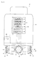
Fig. 1 is a block diagram showing the configuration of the autonomous mobile device mounted with the route planning device according to the first embodiment. - [
Fig. 2 ]
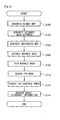
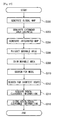
Fig. 2 is a flowchart showing the processing routine of the route planning processing performed by the route planning device according to the first embodiment. - [
Fig. 3 ]
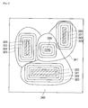
Fig. 3 is a diagram explaining the method of extending the obstacle area (Minkowski sum operation). - [
Fig. 4 ]
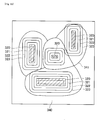
Fig. 4 is a diagram explaining the method of generating an integrated map. - [
Fig. 5 ]
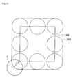
Fig. 5 is a diagram explaining the method of extracting and method of thinning the movable area. - [
Fig. 6 ]
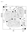
Fig. 6 is a diagram explaining the method of searching for the node. - [
Fig. 7 ]
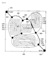
Fig. 7 is a diagram explaining the method of searching for the shortest route. - [
Fig. 8 ]
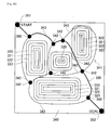
Fig. 8 is a diagram explaining the method of acquiring the route clearance. - [
Fig. 9 ]
Fig. 9 is a block diagram showing the configuration of the autonomous mobile device mounted with the route planning device according to the second embodiment. - [
Fig. 10 ]
Fig. 10 is a diagram explaining the method of extending the obstacle area (Minkowski sum operation). - [
Fig. 11 ]
Fig. 11 is a diagram explaining the method of extracting and method of thinning the movable area. - [
Fig. 12 ]
Fig. 12 is a diagram explaining the method of searching for the node. - [
Fig. 13 ]
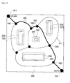
Fig. 13 is a diagram explaining the method of searching for the shortest route. - [
Fig. 14 ]
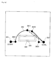
Fig. 14 is a diagram explaining the method of linearizing the travel route. - [
Fig. 15 ]
Fig. 15 is a diagram explaining the method of linearizing the entire travel route. - [
Fig. 16 ]
Fig. 16 is a diagram showing an example of the linearized travel route. - [
Fig. 17 ]
Fig. 17 is a diagram explaining the method of smoothing the travel route. - [
Fig. 18 ]
Fig. 18 is a diagram showing an example of the smoothed travel route. - [
Fig. 19 ]
Fig. 19 is a flowchart showing the processing routine of the route planning processing including the linearization processing and smoothing processing performed by the route planning device according to the second embodiment. - [
Fig. 20 ]
Fig. 20 is a block diagram showing the configuration of the autonomous mobile device according to the third embodiment. - [
Fig. 21 ]
Fig. 21 is a diagram explaining the method of extending the obstacle area (Minkowski sum operation). - [
Fig. 22 ]
Fig. 22 is a diagram explaining the method of generating the integrated map. - [
Fig. 23 ]
Fig. 23 is a diagram explaining the method of extracting and method of thinning the movable area. - [
Fig. 24 ]
Fig. 24 is a diagram explaining the method of searching for the node. - [
Fig. 25 ]
Fig. 25 is a diagram explaining the method of searching for the shortest route. - [
Fig. 26 ]
Fig. 26 is a diagram explaining the method of acquiring the route clearance. - [
Fig. 27 ]
Fig. 27 is a flowchart showing the processing routine of the route planning processing performed by the autonomous mobile device according to the third embodiment. - [
Fig. 28 ]
Fig. 28 is a flowchart showing the processing routine of the travel control processing performed by the autonomous mobile device according to the third embodiment. -
- 1, 2, 3
- autonomous mobile device
- 5, 6
- route planning device
- 10
- main body
- 12
- electric motor
- 13
- omni wheel
- 14
- wheel
- 15
- free roller
- 16
- encoder
- 20
- laser range finder
- 30, 40, 50
- electronic controller
- 31
- global map acquisition unit
- 32
- extended area generation unit
- 33
- integrated map generation unit
- 34
- movable area extraction unit
- 35
- route planning unit
- 41
- linearization unit
- 42
- smoothing unit
- 51
- route clearance acquisition unit
- 52
- storage unit
- 53
- self location detection unit
- 54
- travel control unit
- 55
- route searching unit
- 56
- obstacle avoidance control unit
- The preferred embodiments of the present invention are now explained in detail with reference to the appended drawings. Note that, in the respective drawings, the same elements are given the same reference numeral and redundant explanations are omitted.
- The configuration of a
route planning device 5 and an autonomousmobile device 1 mounted with the foregoingroute planning device 5 according to the first embodiment is foremost explained with reference toFig. 1. Fig. 1 is a functional block diagram showing the configuration of the autonomousmobile device 1 mounted with theroute planning device 5. - The autonomous
mobile device 1 has a function of acquiring an ambient environmental map (map showing an area containing obstacles and an area that does not contain obstacles; hereinafter referred to as the "global map"), planning a travel route which connects the starting point (starting position) and the destination (goal position) on the global map, and autonomously traveling from the starting position to the goal position along the planned route. Note that the starting position and the goal position are given by the user. Thus, the autonomousmobile device 1 comprises amain body 10 provided with anelectric motor 12 at the lower part thereof and anomni wheel 13 that is driven with theelectric motor 12, and alaser range finder 20 for measuring the distance to the obstacles existing in the periphery. Moreover, the autonomousmobile device 1 comprises anelectronic controller 30 which includes aroute planning device 5 for planning the travel route, and which controls theelectric motor 12 so that the autonomousmobile device 1 travels along the planned route. Each of the constituent elements is described in detail below. - The
main body 10 is a metal frame formed, for example, in an approximate cylindrical bottomed shape, and themain body 10 is mounted with the foregoinglaser range finder 20, theelectronic controller 30 including theroute planning device 5, and so on. Note that the shape of themain body 10 is not limited to an approximate cylindrical bottomed shape. At the lower part of themain body 10, fourelectric motors 12 are disposed and mounted in a cross shape. Anomni wheel 13 is mounted to adrive shaft 12A of each of the fourelectric motors 12. Specifically, the fouromni wheels 13 are mounted by being spaced at 90° intervals along the circumferential direction in a concyclic manner. - The
omni wheel 13 is a wheel including twowheels 14 that rotate around thedrive shaft 12A of theelectric motor 12, and sixfree rollers 15 provided rotatably around a shaft that is orthogonal to thedrive shaft 12A of theelectric motor 12 at the outer circumference of therespective wheels 14, and is able to move omnidirectionally. Note that the twowheels 14 are mounted by shifting the phase by 30°. Based on this kind of configuration, when theelectric motor 12 is driven and thewheel 14 is rotated, the sixfree rollers 15 rotate integrally with thewheels 14. Meanwhile, as a result of the groundedfree rollers 15 rotating, theomni wheel 13 can also move in a direction that is parallel with the rotating shaft of thatwheel 14. Thus, by independently controlling the fourelectric motors 12 and independently adjusting the rotating direction and rotating speed of the respective fouromni wheels 13, the autonomousmobile device 1 can be moved in an arbitrary direction (omnidirectionally). - The
drive shaft 12A of each of the fourelectric motors 12 is mounted with anencoder 16 for detecting the angle of rotation of thedrive shaft 12A. Eachencoder 16 is connected to theelectronic controller 30, and outputs the detected angle of rotation of the respectiveelectric motors 12 to theelectronic controller 30. Theelectronic controller 30 computes the travel distance of the autonomousmobile device 1 from the angle of rotation of the respectiveelectric motors 12 that was input. - The
laser range finder 20 is mounted on the front part of the autonomousmobile device 1 so as to face the front (forward) direction of the autonomousmobile device 1. Thelaser range finder 20 scans the circumference of the autonomousmobile device 1 in a fan-like manner in the horizontal direction with a central angle of 240° by emitting a laser and reflecting the emitted laser with a rotating mirror. Subsequently, thelaser range finder 20 detects the laser that was returned by reflecting off an object such as a wall or an obstacle, and detects the angle formed with and the distance to the object by measuring the detection angle of the laser (reflected wave) and the time (propagation time) from the emission of the laser to the return thereof upon being reflected off an object. Note that thelaser range finder 20 is connected to theelectronic controller 30, and outputs, to theelectronic controller 30, the detected distance information and angle information relative to the peripheral object. - The
electronic controller 30 governs the overall control of the autonomousmobile device 1. Theelectronic controller 30 is configured from a microprocessor that performs operations, a ROM that stores programs and the like for causing the microprocessor to execute the respective processes, a RAM that temporarily stores various types of data such as operation results and the like, and a backup RAM that retains stored contents. Moreover, theelectronic controller 30 comprises an interface circuit for electrically connecting thelaser range finder 20 and the microprocessor, a motor driver for driving theelectric motor 12, and so on. - The
electronic controller 30 includes theroute planning device 5 which plans the travel route and acquires the route clearance of the travel route, and plans the travel route as well as controls theelectric motor 12 so that the autonomousmobile device 1 travels along the planned route. Theroute planning device 5 configuring theelectronic controller 30 includes a globalmap acquisition unit 31, an extendedarea generation unit 32, an integratedmap generation unit 33, a movablearea extraction unit 34, and aroute planning unit 35 for planning the travel route and acquiring the route clearance of the travel route. Moreover, theelectronic controller 30 additionally includes a sensorinformation acquisition unit 36, an obstacleinformation acquisition unit 37, a travelcommand calculation unit 38, and a self-information acquisition unit 39. Note that each of the foregoing components is configured by combining the foregoing hardware and software. - The global
map acquisition unit 31 uses, for example, SLAM technology or the like to generate a global map showing an area containing obstacle (obstacle area) and an area that does not contain obstacles. Specifically, the globalmap acquisition unit 31 functions as the environmental map acquisition means described in the claims. Here, a global map is a map that is configured from a plane in which a horizontal plane is divided into blocks of a predetermined size (for example, 1 cm in height and width), and a grid containing an obstacle is given, for example, a value that is greater than "0" and a grid that does not contain an obstacle is given a value that is less than "0". When generating a global map using the SLAM technology, foremost, the globalmap acquisition unit 31 generates a local map based on the distance information and angle information relative to the peripheral object that are read from thelaser range finder 20 via the sensorinformation acquisition unit 36. Moreover, the globalmap acquisition unit 31 acquires the self location from the self-information acquisition unit 39. Note that the self-information acquisition unit 39 verifies the local map and global map in consideration of the calculated travel distance of the autonomousmobile device 1 according to the angle of rotation of the respectiveelectric motors 12 read from theencoder 16, and estimates the self location based on the verification results. Subsequently, the globalmap acquisition unit 31 projects the local map on the global map by performing coordinate transformation to the local map in which thelaser range finder 20 serves as the original point, with the self location being adjusted from the coordinate system in which thelaser range finder 20 serves as the original point to the coordinate system of the global map. The globalmap acquisition unit 31 repeatedly executes this processing while traveling, and generates a global map of the entire ambient environment by sequentially appending (adding) the local map to the global map. - The extended
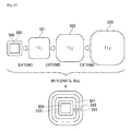
area generation unit 32 extends an outline of the obstacle area contained in the global map generated with the globalmap acquisition unit 31 in an amount corresponding to a radius of the autonomousmobile device 1 to generate an obstacle area that is extended (hereinafter also referred to as the "extended obstacle area"), and additionally extends stepwise an outline of the extended obstacle area in a predetermined range of extension to generate a plurality of extended areas. Specifically, the extendedarea generation unit 32 functions as the extended area generation means described in the claims. For the generation of an extended area, for example, the well known Minkowski sum can be used. Specifically, as shown inFig. 3 , theextended obstacle area 320 is generated by extending the outline (boundary) of theobstacle area 300 in an amount corresponding to the radius r of the autonomousmobile device 1. Based on this processing, the size of the autonomousmobile device 1 can be deemed a point relative to theextended obstacle area 320. In addition, the extendedarea generation unit 32 extends, in three stages, the outline of eachextended obstacle area 320 in each predetermined range of extension to generate three extended areas; specifically, a firstextended area 321, a secondextended area 322, and a third extended area 323 (refer toFig. 4 ). Note that, in this embodiment, the radius r of the autonomousmobile device 1 was used as the predetermined range of extension. Specifically, the extendedarea generation unit 32 generates the firstextended area 321 by extending the outline of theextended obstacle area 320 in an amount corresponding to the radius r of the autonomousmobile device 1, generates the secondextended area 322 by extending the outline of the firstextended area 321 in an amount corresponding to the radius r, and generates the thirdextended area 323 by extending the outline of the secondextended area 322 in an amount corresponding to the radius r. - The integrated
map generation unit 33 generates an integrated map by superposing and integrating the plurality of extended areas generated with the extended area generation unit 32 (in this embodiment, theextended obstacle area 320, the firstextended area 321, the secondextended area 322, and the third extended area 323). Specifically, the integratedmap generation unit 33 functions as the integrated map generation means described in the claims. More specifically, as shown inFig. 4 , the integrated map is generated by superposing and integrating theextended obstacle area 320 and the respectiveextended areas 321 to 323 after giving, for example, a value (weight) of "1" to all grids respectively contained in theextended obstacle area 320, the firstextended area 321, the secondextended area 322, and the thirdextended area 323. Specifically, the integrated value (weight) of the area where the firstextended area 321, the secondextended area 322 and the thirdextended area 323 overlap in the integrated map is "3". Similarly, the integrated value (weight) of an area where only the secondextended area 322 and the thirdextended area 323 overlap (area in which the firstextended area 321 is excluded from the second extended area 322) is "2". Moreover, the value (weight) of an area only containing the third extended area 323 (area in which the secondextended area 322 is excluded from the third extended area 323) is "1". Thus, the integrated value of the respective areas (respective grids) on the integrated map represents a value corresponding to the distance from the extended obstacle area 320 (that is, the obstacle) with the radius r of the autonomousmobile device 1 as a unit, and is represented as being closer to an obstacle in an area (grid) with a greater integrated value, and, contrarily, as being distant from an obstacle in an area (grid) with a smaller integrated value. Accordingly, the distance (route clearance) to the obstacle can be comprehended from the integrated value of the respective areas (respective grids) on the integrated map. - The movable
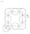
area extraction unit 34 extracts, from the integrated map generated with the integratedmap generation unit 33, an area (movable area) where the autonomousmobile device 1 can travel without coming in contact with an obstacle. Specifically, the movablearea extraction unit 34 functions as the movable area extraction means described in the claims. As shown inFig. 5 , in this embodiment, an area other than the extended obstacle area 320 (area excluding the shaded area inFig. 5 ) on the integrated map is extracted as themovable area 340. Moreover, the movablearea extraction unit 34 performs the thinning processing of the extractedmovable area 340. The thinning processing of themovable area 340 can be performed, for example, by using the well known Hilditch thinning method. Specifically, the movablearea extraction unit 34 performs the thinning processing of themovable area 340 by eliminating one pixel at a time from theextended obstacle area 320 until themovable area 340 becomes a line. Accordingly, the linearmovable area 341 obtained with the thinning processing represents the movable area that is the farthest from an obstacle existing in the periphery. - The
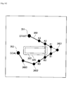
route planning unit 35 plans the travel route by searching for the shortest route that connects the starting position and the goal position within themovable area 341 that was extracted and thinned with the movablearea extraction unit 34. Moreover, theroute planning unit 35 acquires the clearance of the route at the pass-through point (hereinafter also referred to as the "sub goal") from theextended areas 321 to 323 on the integrated map to which the sub goal on the planned travel route belongs. Specifically, theroute planning unit 35 functions as the route planning means described in the claims. More specifically, theroute planning unit 35 foremost executes the node search of the thinnedmovable area 341. Specifically, allnodes 342 are searched and represented as a node map as shown inFig. 6 . Note that, here, the branching point (or integration point) of the thinnedmovable area 341 is referred to as anode 342, and the thinnedmovable area 341 connecting thenode 342 and thenode 342 is referred to as alink 343. - Next, the
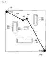
route planning unit 35 performs the shortest route search using a search algorithm such as the well known A* algorithm (A star algorithm) or the like and decides the travel route. Specifically, theroute planning unit 35 decides thetravel route 350 by using, as shown inFig. 7 , the A* algorithm with the startingposition 351 and thegoal position 352 as the base points, and computing through whichnode 342 and which link 343 on the integrated map need to be traveled in order to achieve the minimum cost (shortest route). Subsequently, theroute planning unit 35 acquires, as shown inFig. 8 , the route clearance information for eachsub goal 360 depending on theextended area 321 to 323 to which thesub goal 360 on the decidedtravel route 350 belongs (or theextended area 321 to 323 to which thesub goal 350 does not belong). Here, the foregoing integrated value (for example, "1" "2" "3") of the respective extended areas on the integrated map can be used as the route clearance information. Theroute planning unit 35 associates and adds the acquired route clearance information of therespective sub goals 360 with and to the route information represented as a sub goal point sequence (coordinate sequence) for eachsub goal 360. Route information added with route clearance information is thereby acquired. Note that, when the autonomousmobile device 1 travels along thetravel route 350, the travel of the autonomousmobile device 1 is controlled by the coordinates of the sub goal as the subsequent target pass-through position relative to the self location and the route clearance information at such sub goal being read. - The operation of the
route planning device 5 and the route planning method are now explained with reference toFig. 2 to Fig. 8 .Fig. 2 is a flowchart showing the processing routine of the route planning processing performed by theroute planning device 5. The route planning processing shown inFig. 2 is performed with the route planning device 5 (electronic controller 30), and is executed, for example, based on the user's command operations before performing the autonomous travel. - Foremost, at step S100, a global map is generated based on the distance information, angle information and the like relative to the peripheral object which were read from the
laser range finder 20. Note that the method of generating a global map is as described above, and the detailed explanation thereof is omitted. Next, at step S102, theextended obstacle area 320 is foremost generated by its outline being extended in an amount corresponding to the radius r of the autonomousmobile device 1 for eachobstacle area 300 contained in the global map. At step S102, theextended obstacle area 320 is additionally extended, in three stages, in each predetermined range of extension (radius r of the autonomousmobile device 1 in this embodiment), and three extended areas; specifically, the firstextended area 321, the secondextended area 322, and the thirdextended area 323 are generated (refer toFigs. 3 and4 ). - At subsequent step S104, an integrated map is generated as a result of the
extended obstacle area 320, the firstextended area 321, the secondextended area 322, and the thirdextended area 323 generated at step S102 being superposed and integrated (refer toFig. 4 ). Subsequently, at step S106, the area excluding theextended obstacle area 320 is extracted from the integrated map generated at step S104 as themovable area 340 where the autonomousmobile device 1 can travel without coming in contact with an obstacle (refer toFig. 5 ). Next, at step S108, the thinning processing of the extractedmovable area 340 is performed. Note that the thinning processing of themovable area 340 is as described above, and the detailed explanation thereof is omitted. - At subsequent step S110, the node search of the thinned
movable area 341 is executed (refer toFig. 6 ). Subsequently, at step S112, for example, the A* algorithm is used with the starting position and the goal position as the base points, and through whichnode 342 and which link 343 on the integrated map need to be traveled in order to achieve the minimum cost (shortest route) is computed, and decided as the route 350 (refer toFig. 7 ). - At subsequent step S114, the route clearance information is acquired for each
sub goal 360 depending on theextended area 321 to 323 to which thesub goal 360 on the decidedroute 350 belongs (or theextended area 321 to 323 to which thesub goal 350 does not belong) (refer toFig. 8 ). Route information added with route clearance information is acquired as a result of associating and adding the acquired route clearance information of therespective sub goals 360 with and to the route information represented as a sub goal point sequence (coordinate sequence) for eachsub goal 360. Theelectronic controller 30 controls the advancing speed of the autonomousmobile device 1 so that, for example, when the autonomousmobile device 1 travels along thetravel route 350 that was acquired as described above, the speed upon passing through the route of weight "1" (interval shown with an extra-thick line inFig. 8 ) is reduced in comparison to the speed upon passing through the route of weight "0". Note that, in the foregoing example, although thetravel route 350 does not pass through the area of weight "2", if thetravel route 350 passes through the area of weight "2", the advancing speed can be reduced in comparison to the area of weight "1". Moreover, upon passing through the area of weight "3", the autonomousmobile device 1 can be controlled to derail from thetravel route 350. - According to this embodiment, the
extended obstacle area 320 and the threeextended areas 321 to 323 generated as a result of the outline of theobstacle area 300 being extended stepwise are superposed and integrated, and the integrated map is thereby generated. Accordingly, the boundary of the respectiveextended areas 321 to 323 on the integrated map is disposed according to the distance from the extended obstacle area 320 (that is, from the obstacle). Thus, upon planning thetravel route 350, it is possible to comprehend the route clearance of thesub goal 360 from the integrated value of theextended areas 321 to 323 to which thesub goal 360 on thetravel route 350 belongs. Accordingly, it is possible to comprehend, in advance (at the route planning stage), the route clearance of thesub goal 360 on the plannedtravel route 350. Moreover, according to this embodiment, since it is possible to comprehend the route clearance from the integrated value of theextended areas 321 to 323 to which thesub goal 360 belongs, the route clearance of thesub goal 360 can be recognized with lesser amount of operation. - According to this embodiment, since the outline of the
obstacle area 300 is foremost extended in an amount corresponding to the radius r of the autonomousmobile device 1, the size of the autonomousmobile device 1 relative to the outline of the extended obstacle area 300 (extended obstacle area 320) can be viewed as a point upon extracting themovable area 340. Moreover, since the outline of theextended obstacle area 320 is further extended in a predetermined range of extension (radius r of the autonomousmobile device 1 in this embodiment), the route clearance of the pass-through point on the travel route can be comprehended, with the foregoing range of extension as a unit, as a multiple of the range of extension. Note that, in this embodiment, since the range of extension has been unified to the same value by using the radius r of the autonomousmobile device 1 as the predetermined range of extension, the operation load of theelectronic controller 30 can be reduced. - Since the autonomous
mobile device 1 according to this embodiment comprises the foregoingroute planning device 5, the route clearance of eachsub goal 360 can be comprehended in advance. Accordingly, for example, an appropriate travel speed according to the route clearance of eachsub goal 360 can be set in advance for eachsub goal 360. - An embodiment of the present invention was explained above, but the present invention is not limited to the foregoing embodiment, and can be modified variously. For example, in the foregoing embodiment, although the radius r of the autonomous
mobile device 1 was used as the range of extension upon extending theextended obstacle area 320, the range of extension is not limited to the radius r of the autonomousmobile device 1, and may be arbitrarily set. Moreover, in the foregoing embodiment, although theextended obstacle area 320 was extended in three stages, it may also be extended in two stages or four stages or more. In addition, the value (weight) that is given to the grids configuring the respectiveextended areas 321 to 323 upon integrating the respectiveextended areas 321 to 323 is not limited to "1", and an arbitrary value may be set. - In the foregoing embodiment, although the A* algorithm was used for the shortest route search, another algorithm, for example, the Dijkstra method, the best-first search or the like may also be used.
- In the foregoing embodiment, although the SLAM technology was used upon generating a global map, the global map may also be generated using a method other than SLAM. Moreover, the global map may also be generated from an architectural drawing, or a global map generated with another device may be transferred to the autonomous
mobile device 1. Moreover, although thelaser range finder 20 was used for measuring the distance to the obstacle upon generating a global map, the configuration may use, in substitute for or in addition to the laser range finder, for example, a stereo camera, an ultrasonic sensor and the like. - In the foregoing embodiment, although an
omni wheel 13 capable of moving in all directions was used as the wheel, the configuration may also use a standard wheel (steering wheel and drive wheel). - The configuration of a
route planning device 6 and an autonomousmobile device 2 mounted with the foregoingroute planning device 6 according to the second embodiment is now explained with reference toFig. 9. Fig. 9 is a block diagram showing the configuration of the autonomousmobile device 2 mounted with theroute planning device 6. - The autonomous
mobile device 2 has a function of generating an ambient environmental map (map showing an area containing obstacles and an area that does not contain obstacles; hereinafter referred to as the "global map"), planning a travel route which connects the starting point (start point) and the destination (goal point) on the global map given by the user, and autonomously traveling from the start point to the goal point along the planned route. Thus, the autonomousmobile device 2 comprises amain body 10 provided with anelectric motor 12 at the lower part thereof and anomni wheel 13 that is driven with theelectric motor 12, and alaser range finder 20 for measuring the distance to the obstacles existing in the periphery. Moreover, the autonomousmobile device 2 comprises anelectronic controller 40 which includes aroute planning device 6 for planning the travel route, and which controls theelectric motor 12 so that the autonomousmobile device 2 travels along the planned route. Each of the constituent elements is described in detail below. - The
main body 10 is a metal frame formed, for example, in an approximate cylindrical bottomed shape, and themain body 10 is mounted with the foregoinglaser range finder 20, theelectronic controller 40 including theroute planning device 6, and so on. Note that the shape of themain body 10 is not limited to an approximate cylindrical bottomed shape. At the lower part of themain body 10, fourelectric motors 12 are disposed and mounted in a cross shape. Anomni wheel 13 is mounted to adrive shaft 12A of each of the fourelectric motors 12. Specifically, the fouromni wheels 13 are mounted by being spaced at 90° intervals along the circumferential direction in a concyclic manner. - The
omni wheel 13 is a wheel including twowheels 14 that rotate around thedrive shaft 12A of theelectric motor 12, and sixfree rollers 15 provided rotatably around a shaft that is orthogonal to thedrive shaft 12A of theelectric motor 12 at the outer circumference of therespective wheels 14, and is able to move omnidirectionally. Note that the twowheels 14 are mounted by shifting the phase by 30°. Based on this kind of configuration, when theelectric motor 12 is driven and thewheel 14 is rotated, the sixfree rollers 15 rotate integrally with thewheels 14. Meanwhile, as a result of the groundedfree rollers 15 rotating, theomni wheel 13 can also move in a direction that is parallel with the rotating shaft of thatwheel 14. Thus, by independently controlling the fourelectric motors 12 and independently adjusting the rotating direction and rotating speed of the respective fouromni wheels 13, the autonomousmobile device 2 can be moved in an arbitrary direction (omnidirectionally). - The
drive shaft 12A of each of the fourelectric motors 12 is mounted with anencoder 16 for detecting the angle of rotation of thedrive shaft 12A. Eachencoder 16 is connected to theelectronic controller 40, and outputs the detected angle of rotation of the respectiveelectric motors 12 to theelectronic controller 40. Theelectronic controller 40 computes the travel distance of the autonomousmobile device 2 from the angle of rotation of the respectiveelectric motors 12 that was input. - The
laser range finder 20 is mounted on the front part of the autonomousmobile device 2 so as to face the front (forward) direction of the autonomousmobile device 2. Thelaser range finder 20 scans the circumference of the autonomousmobile device 2 in a fan-like manner in the horizontal direction with a central angle of 240° by emitting a laser and reflecting the emitted laser with a rotating mirror. Subsequently, thelaser range finder 20 detects the laser that was returned by reflecting off an object such as a wall or an obstacle, and detects the angle formed with and the distance to the object by measuring the detection angle of the laser (reflected wave) and the time (propagation time) from the emission of the laser to the return thereof upon being reflected off an object. Note that thelaser range finder 20 is connected to theelectronic controller 40, and outputs, to theelectronic controller 40, the detected distance information and angle information relative to the peripheral object. - The
electronic controller 40 governs the overall control of the autonomousmobile device 2. Theelectronic controller 40 is configured from a microprocessor that performs operations, a ROM that stores programs and the like for causing the microprocessor to execute the respective processes, a RAM that temporarily stores various types of data such as operation results and the like, and a backup RAM that retains stored contents. Moreover, theelectronic controller 40 comprises an interface circuit for electrically connecting thelaser range finder 20 and the microprocessor, a driver circuit for driving theelectric motor 12, and so on. - The
electronic controller 40 includes theroute planning device 6 which plans the travel route, and plans the travel route as well as controls theelectric motor 12 so that the autonomousmobile device 2 travels along the planned route. Theroute planning device 6 includes a globalmap acquisition unit 31, an extendedarea generation unit 32, a movablearea extraction unit 34, aroute planning unit 35, alinearization unit 41, and a smoothingunit 42 for generating the travel route and performing linearization and smoothing to the generated travel route. Note that each of the foregoing components is configured by combining the foregoing hardware and software. - The global
map acquisition unit 31 uses, for example, SLAM technology or the like to generate a global map showing an area containing obstacle (obstacle area) and an area that does not contain obstacles. Specifically, the globalmap acquisition unit 31 functions as the environmental map acquisition means described in the claims. Here, a global map is a map that is configured from a plane in which a horizontal plane is divided into blocks of a predetermined size (for example, 1 cm x 1 cm), and a grid containing an obstacle is given, for example, a value that is greater than "0" and a grid that does not contain an obstacle is given a value that is less than "0". - When generating a global map using the SLAM technology, foremost, the global
map acquisition unit 31 generates a local map based on the distance information and angle information relative to the peripheral object that are read from thelaser range finder 20, and additionally computes the travel distance of the autonomousmobile device 2 based on the angle of rotation of the respectiveelectric motors 12 read from theencoder 16. Next, the globalmap acquisition unit 31 stochastically estimates the self location using the Bayesian filtering (Bayes' theorem) from the generated local map and the travel distance of the autonomousmobile device 2. Subsequently, the globalmap acquisition unit 31 projects the local map on the global map by performing coordinate transformation to the local map in which thelaser range finder 20 serves as the original point, with the self location being adjusted from the coordinate system in which thelaser range finder 20 serves as the original point to the coordinate system of the global map. The globalmap acquisition unit 31 repeatedly executes this processing while traveling, and generates a global map of the entire ambient environment by sequentially appending (adding) the local map to the global map. - The extended
area generation unit 32 extends an outline of the obstacle area contained in the global map generated with the globalmap acquisition unit 31 in an amount corresponding to a radius of the autonomousmobile device 2 to generate the extended area. For the generation of an extended area, for example, the well known Minkowski sum can be used. Specifically, as shown inFig. 10 , the obstacle area that is extended (hereinafter also referred to as the "extended obstacle area") 320 is generated by extending the outline (boundary) of theobstacle area 300 in an amount corresponding to the radius r of the autonomousmobile device 2. Based on this processing, the size of the autonomousmobile device 2 can be deemed a point relative to theextended obstacle area 320. - The movable
area extraction unit 34 extracts, from the global map with an extended obstacle area, an area (movable area) where the autonomousmobile device 2 can travel without coming in contact with an obstacle. Specifically, the movablearea extraction unit 34 functions as the movable area extraction means described in the claims. As shown inFig. 11 , in this embodiment, an area excluding theextended obstacle area 320 on the global map is extracted as themovable area 340. Moreover, the movablearea extraction unit 34 performs the thinning processing of the extractedmovable area 340. The thinning processing of themovable area 340 can be performed, for example, by using the well known Hilditch thinning method. Specifically, the movablearea extraction unit 34 performs the thinning processing of themovable area 340 by eliminating one pixel at a time from theextended obstacle area 320 until themovable area 340 becomes a line. Accordingly, the linearmovable area 341 obtained with the thinning processing represents the movable area that is the farthest from an obstacle existing in the periphery. - The
route planning unit 35 plans the travel route by searching for the shortest route that connects the start point and the goal point within themovable area 341 that was extracted and thinned with the movablearea extraction unit 34. Specifically, theroute planning unit 35 functions as the route planning means described in the claims. More specifically, theroute planning unit 35 foremost executes the node search of the thinnedmovable area 341. Specifically, all nodes are searched and represented as a node map as shown inFig. 12 . Note that, here, the branching point (or integration point) of the thinnedmovable area 341 is referred to as anode 342, and the thinnedmovable area 341 connecting thenode 342 and thenode 342 is referred to as alink 343. - Next, the
route planning unit 35 performs the shortest route search using a search algorithm such as the well known A* algorithm (A star algorithm) or the like and decides the travel route, and the target pass-through point (hereinafter also referred to as the "sub goal") on the travel route. Specifically, theroute planning unit 35 decides thetravel route 350 by using, as shown inFig. 13 , the A* algorithm with thestart point 351 and thegoal point 352 as the base points, and computing through whichnode 342 and which link 343 on the global map need to be traveled in order to achieve the minimum cost (shortest route), and additionally decides thesub goal 360 on thetravel route 350. Theroute planning unit 35 acquires the route information which represents the decidedtravel route 350 as a sub goal point sequence (coordinate sequence). - The
linearization unit 41 performs linearization processing to thetravel route 350 planned with theroute planning unit 35 without interfering with theextended obstacle area 320. More specifically, thelinearization unit 41 extracts two points (hereinafter also referred to as the "sub goal candidates") on thetravel route 350 and connects the two points with a straight line, and, if the connected straight line does not interfere with theextended obstacle area 320, re-sets the straight line as the travel route connecting the foregoing two points. Note that, in the foregoing case, thesub goal 360 sandwiched between the foregoing two points is deleted. Specifically, thelinearization unit 41 functions as the linearization means described in the claims. - Here, the method of linearizing the
travel route 350 is now explained in further detail with reference toFig. 14 . Note that the explanation is provided on the assumption that the travel route 350 (start 351,first sub goal 3601,second sub goal 3602, goal 352) shown inFig. 14 was acquired. Foremost, if thegoal 352 and thesub goal candidate 3610 are extracted, since the straight line connecting these two points does not interfere with theextended obstacle area 320, this straight line is re-set as the travel route. Moreover, in the foregoing case, thesub goal candidate 3610 is set as the official sub goal, and thesecond sub goal 3602 sandwiched between the foregoing two points is deleted. Meanwhile, if thegoal 352 and thesub goal candidate 3611 are extracted, the straight line connecting these two points will interfere with theextended obstacle area 320. Thus, this straight line is not re-set as the travel route. - Moreover, as shown in
Fig. 15 , thelinearization unit 41 repeatedly executes the foregoing linearization processing from thegoal 352 to thestart 351, and re-sets thetravel route 350 and thesub goal 360. Here, thelinearization unit 41 performs the linearization processing to thetravel route 350 from thegoal 352 to the start 351 according to the following routine. - 1. The sub goal candidates (
locations goal 352 in the direction of thestart 351 on thetravel route 350. - 2. A straight line is drawn between the
goal 352 and a sub goal candidate (location n). - 3. Whether the newly drawn straight line interferes with the
extended obstacle area 320 is checked. - 4. When n = N + 1, if the newly drawn straight line interferes with the
extended obstacle area 320, the sub goal candidate of the location N is re-set as thenew sub goal 360. - 5. The routine of foregoing
processes 1 to 4 is repeatedly executed while tracing from thenew sub goal 360 in the direction of thestart 351 on thetravel route 350 to sequentially re-set thesub goal 360, and this routine is ended upon reaching thestart 351. - The smoothing
unit 42 performs the smoothing processing to thetravel route 350 linearized with thelinearization unit 41 without interfering with theextended obstacle area 320. More specifically, the smoothingunit 42 extracts thesub goal 360 on thetravel route 350 and two points (sub goal candidates) on thetravel route 350 sandwiching thesub goal 360, connects the two points with a straight line, and, if the connected straight line does not interfere with theextended obstacle area 320, re-sets the straight line as the travel route connecting the two points. Note that, in the foregoing case, thesub goal 360 sandwiched between the foregoing two points is deleted. Specifically, the smoothingunit 42 functions as the smoothing means described in the claims. - Here, the method of smoothing the
travel route 350 is explained in further detail with reference toFig. 17 . Note that the explanation is provided on the assumption that the travel route 350 (start 351,first sub goal 3601,second sub goal 3602,third sub goal 3603, goal 352) shown inFig. 17 was acquired. The smoothingunit 42 performs the smoothing of thetravel route 350 according to the following routine. - 1. The three points of the
start 351, thefirst sub goal 3601, and thesecond sub goal 3602 are extracted. - 2. If the angle formed by the three points is not greater than a certain value (this value is decided according to the mobility of the autonomous mobile device 2), the routine proceeds to the following
process 3. Meanwhile, if the angle formed by the three points is greater than the foregoing certain value, the routine returns to process 1, the following three points; that is, the three points of thefirst sub goal 3601, thesecond sub goal 3602, and thethird sub goal 3603 are extracted, and this process is performed once again. - 3. The sub goal candidates (locations A1, A2, A3, ..., An, ..., AN, AN + 1, ...) are set by tracing one predetermined grid (for example, one grid) at a time from the
first sub goal 3601 in the direction of thestart 351 on thetravel route 350. - 4. Similarly, the sub goal candidates (locations B1, B2, B3, ..., Bn, ..., BN, BN + 1, ...) are set by tracing, for example, one grid at a time from the
first sub goal 3601 in the direction of thesecond sub goal 3602 on thetravel route 350. - 5. A straight line is drawn between the pair of sub goal candidates (locations An, Bn).
- 6. Whether the newly drawn straight line interferes with the
extended obstacle area 320 is checked. - 7. When n = N + 1, if the newly drawn straight line interferes with the
extended obstacle area 320, the pair of the sub goal candidate of the locations AN and BN (A1 and B1 inFig. 17 ) is re-set as thenew sub goal 360. - 8. Next, the
sub goal 360 of the location BN (B1 inFig. 17 ), thesecond sub goal 3602, and thethird sub goal 3603 are extracted, the same routine as above (processes 1 to 7) is performed, and this routine is ended upon reaching thegoal 352. - The operation of the
route planning device 6 is now explained with reference toFig. 19. Fig. 19 is a flowchart showing the processing routine of the route planning processing including the linearization processing and smoothing processing performed by theroute planning device 6. The route planning processing shown inFig. 19 is performed with the route planning device 6 (electronic controller 40), and is executed, for example, based on the user's command operations before performing the autonomous travel. - Foremost, at step S200, a global map is generated based on the distance information, angle information and the like relative to the peripheral object which were read from the
laser range finder 20. Note that the method of generating a global map is as described above, and the detailed explanation thereof is omitted. Next, at step S202, theextended obstacle area 320 is generated by its outline being extended in an amount corresponding to the radius r of the autonomousmobile device 2 for eachobstacle area 300 contained in the global map (refer toFig. 10 ). - At subsequent step S204, the area excluding the
extended obstacle area 320 generated from the global map at step S202 is extracted as themovable area 340 where the autonomousmobile device 2 can travel without coming in contact with an obstacle. Subsequently, at step S206, the thinning processing of the extractedmovable area 340 is performed (refer toFig. 11 ). Note that the thinning processing of themovable area 340 is as described above, and the detailed explanation thereof is omitted. - Next, at step S208, the node search of the thinned
movable area 341 is executed (refer toFig. 12 ). Subsequently, at step S210, for example, the A* algorithm is used with thestarting point 351 andgoal point 352 as the base points, and through whichnode 342 and which link 343 on the integrated map need to be traveled in order to achieve the minimum cost (shortest route) is computed, thetravel route 350 and thesub goal 360 are thereby decided, and the route information represented as a sub goal point sequence (coordinate sequence) is acquired (refer toFig. 13 ). - Subsequently, at step S212, the linearization processing of the
travel route 350 is performed from thegoal 352 to the start 351 (refer toFigs. 14 to 16 ). Note that the linearization of thetravel route 350 is as described above, and the detailed explanation thereof is omitted. - Subsequently, at step S214, the smoothing processing of the
travel route 350 that was linearized at step S212 is performed (refer toFigs. 17 and18 ). Note that the smoothing of thetravel route 350 is as described above, and the detailed explanation thereof is omitted. - According to this embodiment, the planned
travel route 350 is linearized without interfering with theextended obstacle area 320. Thus, for example, even in cases where a zigzag travel route is planned by theroute planning unit 35, the travel route can be linearized within a range that it will not come in contact with an obstacle. Consequently, it is possible to plan a travel route on which the autonomousmobile device 2 can travel more smoothly. Note that, according to this embodiment, if the straight line connecting the two points on the extractedtravel route 350 does not interfere with theextended obstacle area 320, the straight line connecting the two points is re-set as thetravel route 350. Thus, thetravel route 350 can be linearized appropriately and reliably without interfering with theextended obstacle area 320. - Moreover, according to this embodiment, the linearization of the
travel route 350 is repeatedly performed from thegoal 352 to the start 351 on thetravel route 350. Thus, linearization can be performed across theentire travel route 350 from thestart 351 to thegoal 352 of thetravel route 350. - According to this embodiment, the
travel route 350 is smoothed without interfering with theextended obstacle area 320. Thus, for example, even in cases where a travel route with a sharp angle is planned by theroute planning unit 35, the travel route can be smoothed within a range that it will not come in contact with an obstacle. Consequently, it is possible to plan a travel route on which the autonomousmobile device 2 can travel more smoothly. Note that, according to this embodiment, if the straight line connecting the two points sandwiching thesub goal 360 on the extractedtravel route 350 does not interfere with theextended obstacle area 320, the straight line connecting the two points is re-set as thetravel route 350. Thus, thetravel route 350 can be smoothed appropriately and reliably without interfering with theextended obstacle area 320. - Moreover, according to this embodiment, the smoothing of the
travel route 350 is repeatedly performed from thestart 351 to thegoal 352 on thetravel route 350. Thus, smoothing can be performed across theentire travel route 350 from thestart 351 to thegoal 352 of thetravel route 350. - According to this embodiment, since the
travel route 350 is linearized and additionally smoothed thereafter, thetravel route 350 can be simplified even further. Thus, for example, even in cases where the travel route is planned with complicated bends by theroute planning unit 35, the travel route can be simplified within a range that it will not come in contact with an obstacle. Consequently, it is possible to plan a travel route on which the autonomousmobile device 2 which travels along a travel route can travel more smoothly. - Since the autonomous
mobile device 2 according to this embodiment comprises the foregoingroute planning device 6, it is possible to acquire thetravel route 350 that was linearized and smoothed without interfering with the obstacle; specifically, thetravel route 350 with a shape of being more appropriate for the travel of the autonomousmobile device 2. Consequently, the autonomousmobile device 2 can travel more smoothly upon traveling along thetravel route 350 planned with the autonomousmobile device 2. - An embodiment of the present invention was explained above, but the present invention is not limited to the foregoing embodiment, and can be modified variously. For example, in the foregoing embodiment, although the linearization and smoothing of the
travel route 350 were performed, the configuration may be such that only either one of linearization or smoothing is performed. Moreover, in the foregoing embodiment, although the linearization and smoothing between thegoal 352 and thestart 351 were performed, the configuration may also be such that the linearization and/or smoothing is performed partially. - Moreover, in this embodiment, although the sub goal candidate was set one grid at a time, the width of setting the sub goal candidate is not limited to the foregoing embodiment, and may be set arbitrarily. In addition, the planning method of the
original travel route 350 applied to linearization and smoothing is not limited to this embodiment. - In this embodiment, although the A* algorithm was used for the shortest route search, another algorithm, for example, the Dijkstra method, the best-first search or the like may also be used.
- In this embodiment, although the SLAM technology was used upon generating a global map, the global map may also be generated using a method other than SLAM. Moreover, a global map generated with another device may be transferred. Moreover, although the
laser range finder 20 was used for measuring the distance to the obstacle upon generating a global map, the configuration may use, in substitute for or in addition to the laser range finder, for example, a stereo camera, an ultrasonic sensor and the like. - The configuration of the autonomous
mobile device 3 according to the third embodiment is now explained with reference toFig. 20. Fig. 20 is a block diagram showing the configuration of the autonomousmobile device 3. - The autonomous
mobile device 3 acquires an ambient environmental map (map showing an area containing obstacles and an area that does not contain obstacles; hereinafter referred to as the "global map"), plans a travel route which connects the starting point (starting position) and the destination (goal position) on the global map given by the user, and acquires the route clearance of the travel route. Moreover, the autonomousmobile device 3 autonomously travels from the starting position to the goal position along the planned travel route, and, upon traveling, performs travel control (for example, adjustment of the travel speed) according to the route clearance of the self location (travel point). Thus, the autonomousmobile device 3 comprises amain body 10 provided with anelectric motor 12 at the lower part thereof and anomni wheel 13 that is driven with theelectric motor 12, alaser range finder 20 for measuring the distance to the obstacles existing in the periphery,electronic controller 50 which plans the travel route and drives theelectric motor 12 so that the autonomousmobile device 3 travels along the travel route, acquires the route clearance at the self location (travel point) and controls theelectric motor 12 according to the route clearance, and so on. Each of the constituent elements is described in detail below. - The
main body 10 is a metal frame formed, for example, in an approximate cylindrical bottomed shape, and themain body 10 is mounted with the foregoinglaser range finder 20, theelectronic controller 50, and so on. Note that the shape of themain body 10 is not limited to an approximate cylindrical bottomed shape. At the lower part of themain body 10, fourelectric motors 12 are disposed and mounted in a cross shape. Anomni wheel 13 is mounted to adrive shaft 12A of each of the fourelectric motors 12. Specifically, the fouromni wheels 13 are mounted by being spaced at 90° intervals along the circumferential direction in a concyclic manner. - The
omni wheel 13 is a wheel including twowheels 14 that rotate around thedrive shaft 12A of theelectric motor 12, and sixfree rollers 15 provided rotatably around a shaft that is orthogonal to thedrive shaft 12A of theelectric motor 12 at the outer circumference of therespective wheels 14, and is able to move omnidirectionally. Note that the twowheels 14 are mounted by shifting the phase by 30°. Based on this kind of configuration, when theelectric motor 12 is driven and thewheel 14 is rotated, the sixfree rollers 15 rotate integrally with thewheels 14. Meanwhile, as a result of the groundedfree rollers 15 rotating, theomni wheel 13 can also move in a direction that is parallel with the rotating shaft of thatwheel 14. Thus, by independently controlling the fourelectric motors 12 and independently adjusting the rotating direction and rotating speed of the respective fouromni wheels 13, the autonomousmobile device 3 can be moved in an arbitrary direction (omnidirectionally). Specifically, theelectric motor 12 and theomni wheel 13 function as the moving means described in the claims. - The
drive shaft 12A of each of the fourelectric motors 12 is mounted with anencoder 16 for detecting the angle of rotation of thedrive shaft 12A. Eachencoder 16 is connected to theelectronic controller 50, and outputs the detected angle of rotation of the respectiveelectric motors 12 to theelectronic controller 50. Theelectronic controller 50 computes the travel distance of the autonomousmobile device 3 from the angle of rotation of the respectiveelectric motors 12 that was input. - The
laser range finder 20 is mounted on the front part of the autonomousmobile device 3 so as to face the front (forward) direction of the autonomousmobile device 3. Thelaser range finder 20 scans the circumference of the autonomousmobile device 1 in a fan-like manner in the horizontal direction with a central angle of 240° by emitting a laser and reflecting the emitted laser with a rotating mirror. Subsequently, thelaser range finder 20 detects the laser that was returned by reflecting off an object such as a wall or an obstacle, and detects the angle formed with and the distance to the object by measuring the detection angle of the laser (reflected wave) and the time (propagation time) from the emission of the laser to the return thereof upon being reflected off an object. Note that thelaser range finder 20 is connected to theelectronic controller 50, and outputs, to theelectronic controller 50, the detected distance information and angle information relative to the peripheral object. - The
electronic controller 50 governs the overall control of the autonomousmobile device 3. Theelectronic controller 50 is configured from a microprocessor that performs operations, a ROM that stores programs and the like for causing the microprocessor to execute the respective processes described later, a RAM that temporarily stores various types of data such as operation results and the like, and a backup RAM that retains stored contents. Moreover, theelectronic controller 50 comprises an interface circuit for electrically connecting thelaser range finder 20 and the microprocessor, a driver circuit for driving theelectric motor 12, and so on. - As described above, the
electronic controller 50 plans the travel route, drives theelectric motor 12 so that the autonomousmobile device 3 travels along the travel route, acquires the route clearance at the self location (travel point), and controls theelectric motor 12 according to the route clearance. Thus, theelectronic controller 50 comprises a globalmap acquisition unit 31 for acquiring a global map, aroute planning unit 35 for planning a travel route, a routeclearance acquisition unit 51 for acquiring a route clearance of the travel route, astorage unit 52 for storing the travel route and the route clearance of the travel route, a selflocation detection unit 53 for detecting the self location, and atravel control unit 54 for controlling theelectric motor 12 according to the route clearance at the self location. Note that each of the foregoing components is configured by combining the foregoing hardware and software. - The global
map acquisition unit 31 uses, for example, SLAM technology or the like to generate a global map recording an area containing obstacle (obstacle area) and an area that does not contain obstacles. Specifically, the globalmap acquisition unit 31 functions as the environmental map acquisition means described in the claims. Here, a global map is a map that is configured from a plane in which a horizontal plane is divided into blocks of a predetermined size (for example, 1 cm in height and width), and a grid containing an obstacle is given, for example, a value that is greater than "0" and a grid that does not contain an obstacle is given a value that is less than "0". When generating a global map using the SLAM technology, foremost, the globalmap acquisition unit 31 reads the self location acquired with the selflocation detection unit 53 described later. Note that the method of acquiring the self location will be described in detail later. Next, the globalmap acquisition unit 31 projects the local map on the global map by performing coordinate transformation to the local map in which thelaser range finder 20 serves as the original point, with the self location being adjusted from the coordinate system, in which thelaser range finder 20 generated upon acquiring the self location serves as the original point, to the coordinate system of the global map. The globalmap acquisition unit 31 repeatedly executes this processing while traveling, and generates a global map of the entire ambient environment by sequentially appending (adding) the local map to the global map. - The
route planning unit 35 includes an extendedarea generation unit 32, an integratedmap generation unit 33, a movablearea extraction unit 34, and aroute searching unit 55 in order to plan the travel route from the global map generated with the globalmap acquisition unit 31. Theroute planning unit 35 functions as the route planning means described in the claims. - The extended
area generation unit 32 extends an outline of the obstacle area contained in the global map generated with the globalmap acquisition unit 31 in an amount corresponding to a radius of the autonomousmobile device 3 to generate an obstacle area that is extended (hereinafter also referred to as the "extended obstacle area"), and additionally extends stepwise an outline of the extended obstacle area in a predetermined range of extension to generate a plurality of extended areas. For the generation of an extended area, for example, the well known Minkowski sum can be used. Specifically, as shown inFig. 21 , theextended obstacle area 320 is generated by extending the outline (boundary) of theobstacle area 300 in an amount corresponding to the radius r of the autonomousmobile device 3. Based on this processing, the size of the autonomousmobile device 3 can be deemed a point relative to theextended obstacle area 320. In addition, the extendedarea generation unit 32 extends, in three stages, the outline of eachextended obstacle area 320 in each predetermined range of extension to generate three extended areas; specifically, a firstextended area 321, a secondextended area 322, and a third extended area 323 (refer toFig. 22 ). Note that, in this embodiment, the radius r of the autonomousmobile device 3 was used as the predetermined range of extension. Specifically, the extendedarea generation unit 32 generates the firstextended area 321 by extending the outline of theextended obstacle area 320 in an amount corresponding to the radius r of the autonomousmobile device 3, generates the secondextended area 322 by extending the outline of the firstextended area 321 in an amount corresponding to the radius r, and generates the thirdextended area 323 by extending the outline of the secondextended area 322 in an amount corresponding to the radius r. - The integrated
map generation unit 33 generates an integrated map by superposing and integrating the plurality of extended areas generated with the extended area generation unit 32 (in this embodiment, theextended obstacle area 320, the firstextended area 321, the secondextended area 322, and the third extended area 323). More specifically, as shown inFig. 22 , the integrated map is generated by superposing and integrating theextended obstacle area 320 and the respectiveextended areas 321 to 323 after giving, for example, a value (weight) of "1" to all grids respectively contained in theextended obstacle area 320, the firstextended area 321, the secondextended area 322, and the thirdextended area 323. Specifically, the integrated value (weight) of the area where the firstextended area 321, and the secondextended area 322 and the thirdextended area 323 overlap in the integrated map is "3". Similarly, the integrated value (weight) of an area where only the secondextended area 322 and the thirdextended area 323 overlap (area in which the firstextended area 321 is excluded from the second extended area 322) is "2". Moreover, the value (weight) of an area only containing the third extended area 323 (area in which the secondextended area 322 is excluded from the third extended area 323) is "1". Thus, the integrated value of the respective areas (respective grids) on the integrated map represents a value corresponding to the distance from the extended obstacle area 320 (that is, the obstacle) with the radius r of the autonomousmobile device 3 as a unit, and is represented as being closer to an obstacle in an area (grid) with a greater integrated value, and, contrarily, as being distant from an obstacle in an area (grid) with a smaller integrated value. Accordingly, the distance (clearance) to the obstacle can be comprehended from the integrated value of the respective areas (respective grids) on the integrated map. - The movable
area extraction unit 34 extracts, from the integrated map generated with the integratedmap generation unit 33, an area (movable area) where the autonomousmobile device 3 can travel without coming in contact with an obstacle. As shown inFig. 23 , in this embodiment, an area other than the extended obstacle area 320 (area excluding the shaded area inFig. 23 ) on the integrated map is extracted as themovable area 340. Moreover, the movablearea extraction unit 34 performs the thinning processing of the extractedmovable area 340. The thinning processing of themovable area 340 can be performed, for example, by using the well known Hilditch thinning method. Specifically, the movablearea extraction unit 34 performs the thinning processing of themovable area 340 by eliminating one pixel at a time from theextended obstacle area 320 until themovable area 340 becomes a line. Accordingly, the linearmovable area 341 obtained with the thinning processing represents the movable area that is the farthest from an obstacle existing in the periphery. - The
route searching unit 55 plans the travel route by searching for the shortest route that connects the starting position and the goal position within themovable area 341 that was extracted and thinned with the movablearea extraction unit 34. More specifically, theroute searching unit 55 foremost executes the node search of the thinnedmovable area 341. Specifically, allnodes 342 are searched and represented as a node map as shown inFig. 24 . Note that, here, the branching point (or integration point) of the thinnedmovable area 341 is referred to as anode 342, and the thinnedmovable area 341 connecting thenode 342 and thenode 342 is referred to as alink 343. Next, theroute searching unit 55 performs the shortest route search using a search algorithm such as the well known A* algorithm (A star algorithm) or the like and decides the travel route. Specifically, theroute searching unit 55 decides theroute 350 by using, as shown inFig. 25 , the A* algorithm with the startingposition 351 and thegoal position 352 as the base points, and computing through whichnode 342 and which link 343 on the integrated map need to be traveled in order to achieve the minimum cost (shortest route). - The route
clearance acquisition unit 51 acquires the clearance of the route at the pass-through point (hereinafter also referred to as the "sub goal") from theextended areas 321 to 323 on the integrated map to which the sub goal on the travel route planned with theroute searching unit 55 belongs. More specifically, as shown inFig. 26 , the routeclearance acquisition unit 51 acquires the route clearance information for eachsub goal 360 depending on theextended area 321 to 323 to which thesub goal 360 on the decidedtravel route 350 belongs (or theextended area 321 to 323 to which thesub goal 350 does not belong). Here, the foregoing integrated value (for example, "1" "2" "3"; whereby the integrated value of an area that does not belong to any one of the extended areas is "0") of the respective areas on the integrated map can be used as the route clearance information. The routeclearance acquisition unit 51 associates and adds the acquired route clearance information of therespective sub goals 360 with and to the route information represented as a sub goal point sequence (coordinate sequence) for eachsub goal 360. Travel route information added with route clearance information is thereby acquired. Specifically, the routeclearance acquisition unit 51 functions as the route clearance acquisition means described in the claims. - The
storage unit 52 is configured, for example, from the foregoing backup RAM or the like, and stores the route information planned with theroute planning unit 35 and the route clearance information of the travel route acquired with the routeclearance acquisition unit 51. Specifically, thestorage unit 52 functions as the storage means described in the claims. - The self
location detection unit 53 estimates the self location; that is, the location of the autonomousmobile device 3 that is traveling. Accordingly, the selflocation detection unit 53 functions as the self location detection means described in the claims. More specifically, the selflocation detection unit 53 foremost generates a local map based on the distance information and angle information relative to the peripheral object that were read from thelaser range finder 20 via the sensorinformation acquisition unit 36, and additionally computes the travel distance of the autonomousmobile device 3 based on the angle of rotation of the respectiveelectric motors 12 read from theencoder 16. Next, selflocation detection unit 53 stochastically estimates the self location using the Bayesian filtering (Bayes' theorem) from the generated local map and the travel distance of the autonomousmobile device 3. - The
travel control unit 54 acquires the route clearance at the self location based on the self location detected with the selflocation detection unit 53, and the route information and route clearance information stored in thestorage unit 52, and controls the travel of the autonomousmobile device 3 by controlling theelectric motor 12 according to the route clearance. Specifically, thetravel control unit 54 functions as the travel control means described in the claims. More specifically, thetravel control unit 54 foremost detects a sub goal which coincides with or is closest to the self location from the sub goal point sequence (coordinate sequence) contained in the route information, and acquires the route clearance information at that sub goal, which is stored by being associated with that sub goal. Note that, as the route clearance information, rather than adopting a value of one sub goal that is the closest, a value of a sub goal that is positioned on the side that is closer to the goal than the detected closest sub goal and which is the narrowest (largest value) within the route clearance information of a plurality of sub goals contained in a certain definite range from the self range may be used. - Next, the
travel control unit 54 sets the target travel speed according to the acquired route clearance information. For example, thetravel control unit 54 sets the target travel speed to 4 km/h if the route clearance information is "0", sets the target travel speed to 3 km/h if the route clearance information is "1", sets the target travel speed to 2 km/h if the route clearance information is "2", and sets the target travel speed to 1 km/h if the route clearance information is "3". Specifically, the target travel speed is set so that the speed of the autonomousmobile device 3 becomes slower as the route clearance becomes smaller (that is, as the passage width becomes narrower). Note that, in substitute for setting the target travel speed according to the route clearance information, the configuration may be such that a coefficient is set according to the route clearance information, and the coefficient is multiplied with the target travel speed that is set based on other parameters. In the foregoing case, for example, the coefficient is set to "1" if the route clearance information is "0", the coefficient is set to "3/4" if the route clearance information is "1", the coefficient is set to "2/4" if the route clearance information is "2", and the coefficient is set to "1/4" if the route clearance information is "3". Specifically, the coefficient is set so that the travel speed becomes slower as the route clearance becomes smaller. - Moreover, the
travel control unit 54 includes an obstacleavoidance control unit 56 for setting the avoidance force (hereinafter also referred to as the "repulsion") for avoiding obstacles according to the route clearance at the self location, and avoids the obstacles by driving theelectric motor 12 based on the repulsion set with the obstacleavoidance control unit 56. The obstacleavoidance control unit 56 functions as the obstacle avoidance control means described in the claims. Here, in this embodiment, a virtual potential method was adopted as the control method of moving the autonomousmobile device 3 to the goal position while avoiding obstacles. The virtual potential method is a method of generating a virtual gravitation potential field relative to the goal position and a virtual repulsion potential field relative to the obstacle to be avoided, and superposing these to generate a route that heads to the goal position while avoiding contact with the obstacles. In this embodiment, the route clearance is adopted as one parameter for setting the repulsion of the virtual potential method. - More specifically, the
travel control unit 54 foremost calculates the virtual gravitation for heading to the goal position based on the self location. Meanwhile, the obstacleavoidance control unit 56 calculates the virtual repulsion for avoiding obstacles based on the self location, travel speed, position and speed of the obstacle, as well as based on the coefficient that is set according to the speed and route clearance information. Here, as the coefficient that is set as the route clearance information, for example, the same coefficient as the foregoing coefficient that is multiplied with the target travel speed can be used. Specifically, the coefficient is set so that the virtual repulsion becomes smaller (manner of avoidance becomes gradual) as the route clearance becomes smaller. Subsequently, thetravel control unit 54 calculates the virtual force vector by performing vector synthesis to the obtained virtual gravitation and virtual repulsion. Thetravel control unit 54 controls the travel of the autonomousmobile device 3 to move to the goal position while avoiding obstacles by driving the electric motor 12 (omni wheel 13) according to the obtained virtual force vector. - In this embodiment, since the route clearance at the self location is comprehended, it is possible to estimate whether the detected object is the wall of the passage or an obstacle based on the distance to the object detected with the
laser range finder 20. Here, if the detected object is a wall and not an obstacle, the operation taking the foregoing avoidance operation (operation for obtaining the virtual repulsion) can be omitted. - The operation of the autonomous
mobile device 3 is now explained with reference toFig. 27 andFig. 28 .Fig. 27 is a flowchart showing the processing routine of the route planning processing performed by the autonomousmobile device 3. Moreover,Fig. 28 is a flowchart showing the processing routine of the travel control processing performed by the autonomousmobile device 3. The route planning processing shown inFig. 27 is performed by theelectronic controller 50, and is executed, for example, based on the user's command operations before performing the autonomous travel. Moreover, the travel control processing shown inFig. 28 is performed by theelectronic controller 50, and is repeatedly executed at a predetermined timing when the autonomousmobile device 3 is autonomously traveling. - The processing routine of the route planning processing shown in
Fig. 27 is foremost explained. At step S300, a global map is generated based on the distance information, angle information and the like relative to the peripheral object which were read from thelaser range finder 20. Note that the method of generating a global map is as described above, and the detailed explanation thereof is omitted. Next, at step S302, theextended obstacle area 320 is foremost generated by its outline being extended in an amount corresponding to the radius r of the autonomousmobile device 3 for eachobstacle area 300 contained in the global map. At step S302, theextended obstacle area 320 is additionally extended, in three stages, in each predetermined range of extension (radius r of the autonomousmobile device 3 in this embodiment), and three extended areas; specifically, the firstextended area 321, the secondextended area 322, and the thirdextended area 323 are generated (refer toFigs. 21 and22 ). - At subsequent step S304, an integrated map is generated as a result of the
extended obstacle area 320, the firstextended area 321, the secondextended area 322, and the thirdextended area 323 generated at step S302 being superposed and integrated (refer toFig. 22 ). Subsequently, at step S306, the area excluding theextended obstacle area 320 is extracted from the integrated map generated at step S304 as themovable area 340 where the autonomousmobile device 3 can travel without coming in contact with an obstacle (refer toFig. 23 ). Next, at step S308, the thinning processing of the extractedmovable area 340 is performed. Note that the thinning processing of themovable area 340 is as described above, and the detailed explanation thereof is omitted. - At subsequent step S310, the node search of the thinned
movable area 341 is executed (refer toFig. 24 ). Subsequently, at step S312, for example, the A* algorithm is used with the starting position and the goal position as the base points, and through whichnode 342 and which link 343 on the integrated map need to be traveled in order to achieve the minimum cost (shortest route) is searched, and decided as the route 350 (refer toFig. 25 ). - At subsequent step S314, the route clearance information ("0" "1" "2" "3") is acquired for each
sub goal 360 depending on theextended area 321 to 323 to which thesub goal 360 on the decidedroute 350 belongs (or theextended area 321 to 323 to which thesub goal 350 does not belong) (refer toFig. 26 ). Route information added with route clearance information is acquired as a result of associating and adding the acquired route clearance information of therespective sub goals 360 with and to the route information represented as a sub goal point sequence (coordinate sequence) for eachsub goal 360. The route information added with the route clearance information (that is, the route information and route clearance information) acquired at step S314 is stored in thestorage unit 52 at step S316. - The travel control processing shown in
Fig. 28 is now explained. At step S400, the self location during travel is estimated using the Bayesian filtering from the local map generated based on the distance and angle information relative to the object, and the travel distance of the autonomousmobile device 3 that was computed based on the angle of rotation of the respectiveelectric motors 12. At subsequent step S402, a sub goal which coincides with or is closest to the self location is detected from the sub goal point sequence (coordinate sequence) contained in the route information, and the route clearance information at that sub goal, which is stored by being associated with that sub goal, is acquired. Note that, as described above, as the route clearance information, rather than adopting a value of one sub goal that is the closest, a value of a sub goal that is positioned on the side that is closer to the goal than the detected closest sub goal and which is the narrowest (largest value) within the route clearance information of a plurality of sub goals contained in a certain definite range from the self range may be used. - Next, at step S404, the target travel speed is set according to the acquired route clearance information. Here, the target travel speed is set so that the speed of the autonomous
mobile device 3 becomes slower as the route clearance becomes narrower (that is, as the passage width becomes narrower). Note that, since the method of setting the target travel speed is as described above, the detailed explanation thereof is omitted. - Subsequently, at step S406, a virtual repulsion for avoiding obstacles according to the route clearance information acquired at step S402 is set. Here, the virtual repulsion is set so that the virtual repulsion becomes smaller (that is, the manner of avoidance becomes smaller) as the route clearance becomes smaller. Since the method of setting the virtual repulsion is as described above, the detailed explanation thereof is omitted. In addition, at step S406, a virtual gravitation for heading toward the goal position based on the self location is calculated, and a virtual force vector is calculated by the obtained virtual gravitation and virtual repulsion being subject to vector synthesis.
- At subsequent step S408, the electric motor 12 (omni wheel 13) is driven based on the target travel speed set at step S404 and the virtual force vector obtained at step S406. Thus, the travel speed and avoidance force (repulsion) are adjusted to optimal values according to the clearance (passage width) of the route on which the autonomous
mobile device 3 is traveling. - According to this embodiment, a travel route is planned from the acquired global map, and a route clearance of the travel route is acquired. Meanwhile, the route clearance at the self location is comprehended from the detected self location and the acquired route clearance of the travel route. The
electric motor 12 is controlled according to the comprehended route clearance at the self location. Thus, the appropriate travel control can be performed according to the route clearance at the travel point, upon traveling along the travel route. - More specifically, according to this embodiment, the target travel speed is set according to the route clearance of the travel point. Thus, it is possible to travel at an appropriate travel speed according to the route clearance of the travel point. Accordingly, it is possible to travel slowly in a narrow passage, and, contrarily, travel at a faster speed in a wide passage.
- Moreover, according to this embodiment, the repulsion for avoiding obstacles can be adjusted according to the route clearance of the travel point. Thus, it is possible to slowly and narrowly avoid the obstacle in a narrow passage, and, contrarily, quickly avoid, with considerable clearance, the obstacle in a wide passage.
- According to this embodiment, the travel route and the route clearance of the travel route are acquired and stored in advance. Thus, since it is no longer necessary to obtain the route clearance of the travel route while the autonomous mobile device is traveling, it is possible to reduce the calculation load and reduce the control delay while the autonomous mobile device is traveling.
- An embodiment of the present invention was explained above, but the present invention is not limited to the foregoing embodiment, and can be modified variously. For example, in the foregoing embodiment, although the
extended obstacle area 320 was extended stepwise and integrated, and the route clearance at the sub goal was obtained from theextended areas 321 to 323 to which that sub goal belongs, the method of obtaining the route clearance is not limited to the foregoing method. For example, the route clearance may also be obtained by computing the Euclid distance to the obstacle for each sub goal. - Note that, when adopting the foregoing method as the method of obtaining the route clearance, in the foregoing embodiment, although the radius r of the autonomous
mobile device 3 was used as the range of extension upon extending theextended obstacle area 320, the range of extension is not limited to the radius r of the autonomousmobile device 3, and may be arbitrarily set. Moreover, in the foregoing embodiment, although theextended obstacle area 320 was extended in three stages, it may also be extended in two stages or four stages or more. In addition, the value (weight) that is given to the grids configuring the respectiveextended areas 321 to 323 upon integrating the respectiveextended areas 321 to 323 is not limited to "1", and an arbitrary value may be set. - In this embodiment, although the target travel speed and the like are set according to the route clearance of the travel point during autonomous travel, the configuration may also be such that the foregoing target travel speed, coefficient and the like are obtained for each sub goal and stored in the
storage unit 52 in advance at the point in time that the travel route is planned and the route clearance information is acquired. - In this embodiment, although the A* algorithm was used for the shortest route search, another algorithm, for example, the Dijkstra method, the best-first search or the like may also be used.
- In this embodiment, although the SLAM technology was used upon generating a global map, the global map may also be generated using a method other than SLAM. Moreover, a global map generated with another device may be transferred.
- In this embodiment, although the
laser range finder 20 was used for measuring the distance to the obstacle upon generating a global map, the configuration may use, in substitute for or in addition to the laser range finder, for example, a stereo camera, an ultrasonic sensor and the like. - In this embodiment, although an
omni wheel 13 capable of moving in all directions was used as the wheel, the configuration may also use a standard wheel (steering wheel and drive wheel). Moreover, the number ofomni wheels 13 is not limited to four, and, for example, it may be three or six.
Claims (10)
the device comprising the route planning device according to claim 1.
Applications Claiming Priority (4)
| Application Number | Priority Date | Filing Date | Title |
|---|---|---|---|
| JP2008225881A JP5287050B2 (en) | 2008-09-03 | 2008-09-03 | Route planning method, route planning device, and autonomous mobile device |
| JP2008227008A JP5287051B2 (en) | 2008-09-04 | 2008-09-04 | Autonomous mobile device |
| JP2008231519A JP5287060B2 (en) | 2008-09-09 | 2008-09-09 | Route planning device and autonomous mobile device |
| EP09811240.2A EP2343617A4 (en) | 2008-09-03 | 2009-08-24 | Route planning method, route planning unit, and autonomous mobile device |
Related Parent Applications (2)
| Application Number | Title | Priority Date | Filing Date |
|---|---|---|---|
| EP09811240.2A Division EP2343617A4 (en) | 2008-09-03 | 2009-08-24 | Route planning method, route planning unit, and autonomous mobile device |
| PCT/JP2009/004052 Previously-Filed-Application WO2010026710A1 (en) | 2008-09-03 | 2009-08-24 | Route planning method, route planning unit, and autonomous mobile device |
Publications (2)
| Publication Number | Publication Date |
|---|---|
| EP2821875A2 true EP2821875A2 (en) | 2015-01-07 |
| EP2821875A3 EP2821875A3 (en) | 2015-05-20 |
Family
ID=41796896
Family Applications (3)
| Application Number | Title | Priority Date | Filing Date |
|---|---|---|---|
| EP20140166031 Withdrawn EP2821876A3 (en) | 2008-09-03 | 2009-08-24 | Route planning method, route planning unit, and autonomous mobile device |
| EP20140166030 Withdrawn EP2821875A3 (en) | 2008-09-03 | 2009-08-24 | Route planning method, route planning unit, and autonomous mobile device |
| EP09811240.2A Withdrawn EP2343617A4 (en) | 2008-09-03 | 2009-08-24 | Route planning method, route planning unit, and autonomous mobile device |
Family Applications Before (1)
| Application Number | Title | Priority Date | Filing Date |
|---|---|---|---|
| EP20140166031 Withdrawn EP2821876A3 (en) | 2008-09-03 | 2009-08-24 | Route planning method, route planning unit, and autonomous mobile device |
Family Applications After (1)
| Application Number | Title | Priority Date | Filing Date |
|---|---|---|---|
| EP09811240.2A Withdrawn EP2343617A4 (en) | 2008-09-03 | 2009-08-24 | Route planning method, route planning unit, and autonomous mobile device |
Country Status (4)
| Country | Link |
|---|---|
| US (1) | US8515612B2 (en) |
| EP (3) | EP2821876A3 (en) |
| KR (3) | KR101307299B1 (en) |
| WO (1) | WO2010026710A1 (en) |
Families Citing this family (58)
| Publication number | Priority date | Publication date | Assignee | Title |
|---|---|---|---|---|
| JP5398488B2 (en) * | 2009-11-20 | 2014-01-29 | 村田機械株式会社 | Autonomous mobile object and its control method |
| JP5398489B2 (en) * | 2009-11-20 | 2014-01-29 | 村田機械株式会社 | Autonomous mobile object and its control method |
| KR101641237B1 (en) * | 2009-11-20 | 2016-07-21 | 엘지전자 주식회사 | Robot cleaner and controlling method of the same |
| JP5560794B2 (en) * | 2010-03-16 | 2014-07-30 | ソニー株式会社 | Control device, control method and program |
| JP5560978B2 (en) | 2010-07-13 | 2014-07-30 | 村田機械株式会社 | Autonomous mobile |
| JP5560979B2 (en) | 2010-07-13 | 2014-07-30 | 村田機械株式会社 | Autonomous mobile |
| KR101750340B1 (en) * | 2010-11-03 | 2017-06-26 | 엘지전자 주식회사 | Robot cleaner and controlling method of the same |
| WO2013021546A1 (en) * | 2011-08-08 | 2013-02-14 | パナソニック株式会社 | Electric vehicle and method for controlling same |
| US8983709B2 (en) * | 2011-11-09 | 2015-03-17 | Hitachi, Ltd. | Autonomous travel system |
| DE102012206952A1 (en) * | 2012-04-26 | 2013-10-31 | Siemens Aktiengesellschaft | Method and device for controlling the movement of a mobile unit in space |
| TWM451103U (en) * | 2012-10-30 | 2013-04-21 | Agait Technology Corp | Walking device |
| CN103777629A (en) * | 2013-09-05 | 2014-05-07 | 武汉汉迪机器人科技有限公司 | Self-guide carrying platform and navigation control method for carrying platform |
| SG11201603486UA (en) * | 2013-11-30 | 2016-05-30 | Saudi Arabian Oil Co | System and method for calculating the orientation of a device |
| US10048062B2 (en) * | 2014-03-12 | 2018-08-14 | The Chugoku Electric Power Co., Inc. | Distance measuring apparatus and distance measuring method |
| JP6352151B2 (en) * | 2014-11-07 | 2018-07-04 | ソニー株式会社 | Information processing apparatus, information processing system, and information processing method |
| US20200409382A1 (en) * | 2014-11-10 | 2020-12-31 | Carnegie Mellon University | Intelligent cleaning robot |
| US9637318B2 (en) * | 2014-12-16 | 2017-05-02 | Amazon Technologies, Inc. | Mobile configurable conveyor component |
| JP2017004373A (en) * | 2015-06-12 | 2017-01-05 | 株式会社リコー | Information processing device, information processing program, and information processing system |
| WO2017149628A1 (en) * | 2016-02-29 | 2017-09-08 | 株式会社小松製作所 | Work machine management system and work machine |
| US10353400B2 (en) * | 2016-05-23 | 2019-07-16 | Asustek Computer Inc. | Navigation system and navigation method |
| US10589931B2 (en) | 2016-09-30 | 2020-03-17 | Staples, Inc. | Hybrid modular storage fetching system |
| CN109791477A (en) | 2016-09-30 | 2019-05-21 | 史泰博公司 | Hybrid modular storage extraction system |
| US10683171B2 (en) | 2016-09-30 | 2020-06-16 | Staples, Inc. | Hybrid modular storage fetching system |
| WO2018071724A1 (en) * | 2016-10-12 | 2018-04-19 | Google Llc | Selecting actions to be performed by a robotic agent |
| CN106444768B (en) * | 2016-10-20 | 2019-07-09 | 上海物景智能科技有限公司 | A kind of the welt traveling method and system of robot |
| JP7019947B2 (en) * | 2016-12-19 | 2022-02-16 | 富士フイルムビジネスイノベーション株式会社 | Mobile device |
| US10921816B2 (en) * | 2017-04-21 | 2021-02-16 | Korea Advanced Institute Of Science And Technology | Method and apparatus for producing map based on hierarchical structure using 2D laser scanner |
| JP6897376B2 (en) * | 2017-07-11 | 2021-06-30 | トヨタ自動車株式会社 | Movement planning equipment, mobile robots, and movement planning programs |
| CN108052102B (en) * | 2017-12-08 | 2021-09-28 | 成都全景智能科技有限公司 | Robot travel route determining method and device and robot |
| CN108170146B (en) * | 2017-12-31 | 2021-07-30 | 芜湖哈特机器人产业技术研究院有限公司 | Path planning method based on known environment |
| JP7139643B2 (en) | 2018-03-23 | 2022-09-21 | カシオ計算機株式会社 | Robot, robot control method and program |
| CN110388920A (en) * | 2018-04-15 | 2019-10-29 | 张舒怡 | The path planning of robot |
| US11590997B1 (en) | 2018-08-07 | 2023-02-28 | Staples, Inc. | Autonomous shopping cart |
| US11084410B1 (en) | 2018-08-07 | 2021-08-10 | Staples, Inc. | Automated guided vehicle for transporting shelving units |
| US11630447B1 (en) | 2018-08-10 | 2023-04-18 | Staples, Inc. | Automated guided vehicle for transporting objects |
| CN110857859B (en) * | 2018-08-23 | 2022-02-08 | 杭州海康机器人技术有限公司 | Obstacle detection method and device |
| JP7180218B2 (en) * | 2018-09-07 | 2022-11-30 | 株式会社豊田自動織機 | Autonomous cart |
| EP3627250B1 (en) * | 2018-09-21 | 2023-12-06 | Tata Consultancy Services Limited | Method and system for free space detection in a cluttered environment |
| KR102198187B1 (en) * | 2018-12-28 | 2021-01-04 | 엘지전자 주식회사 | Moving robot |
| US11119487B2 (en) | 2018-12-31 | 2021-09-14 | Staples, Inc. | Automated preparation of deliveries in delivery vehicles using automated guided vehicles |
| US11180069B2 (en) | 2018-12-31 | 2021-11-23 | Staples, Inc. | Automated loading of delivery vehicles using automated guided vehicles |
| US10809734B2 (en) | 2019-03-13 | 2020-10-20 | Mobile Industrial Robots A/S | Route planning in an autonomous device |
| CN110020470B (en) * | 2019-03-27 | 2023-06-30 | 苏州华恒展览设计营造有限公司 | Showcase moving method for layout planning in exhibition hall |
| US11124401B1 (en) | 2019-03-31 | 2021-09-21 | Staples, Inc. | Automated loading of delivery vehicles |
| CN110231027B (en) * | 2019-05-20 | 2021-01-19 | 西安交通大学 | Positioning system and positioning method based on multi-sensor data fusion |
| CN110320933B (en) * | 2019-07-29 | 2021-08-10 | 南京航空航天大学 | Unmanned aerial vehicle obstacle avoidance movement planning method under cruise task |
| DE102019216461B3 (en) * | 2019-10-25 | 2021-01-21 | Kuka Deutschland Gmbh | Method for operating an autonomous vehicle, autonomous vehicle and computer program product |
| CN110967032B (en) * | 2019-12-03 | 2022-01-04 | 清华大学 | Real-time planning method for local driving route of unmanned vehicle in field environment |
| CN111121750B (en) * | 2019-12-26 | 2022-04-22 | 广东博智林机器人有限公司 | Indoor path acquisition method and device |
| US11592299B2 (en) | 2020-03-19 | 2023-02-28 | Mobile Industrial Robots A/S | Using static scores to control vehicle operations |
| US11927961B2 (en) | 2020-04-20 | 2024-03-12 | Boston Dynamics, Inc. | Constrained robot autonomy language |
| US11712802B2 (en) * | 2020-04-20 | 2023-08-01 | Boston Dynamics, Inc. | Construction constrained motion primitives from robot maps |
| CN111722630B (en) * | 2020-06-30 | 2024-02-02 | 深圳银星智能集团股份有限公司 | Partition boundary extension method, device and equipment of cleaning robot and storage medium |
| CN112013845B (en) * | 2020-08-10 | 2022-04-22 | 北京轩宇空间科技有限公司 | Fast map updating method, device and storage medium adapting to unknown dynamic space |
| CN112180931B (en) * | 2020-09-30 | 2024-04-12 | 北京小狗吸尘器集团股份有限公司 | Cleaning path planning method and device of sweeper and readable storage medium |
| CN113035195B (en) * | 2021-03-04 | 2022-09-23 | 江西台德智慧科技有限公司 | Artificial intelligence voice interaction terminal equipment |
| JP2022163408A (en) * | 2021-04-14 | 2022-10-26 | トヨタ自動車株式会社 | Robot control system, robot control method, program, and autonomous mobile robot |
| CN113805597B (en) * | 2021-09-28 | 2023-04-11 | 福州大学 | Obstacle self-protection artificial potential field method local path planning method based on particle swarm optimization |
Citations (2)
| Publication number | Priority date | Publication date | Assignee | Title |
|---|---|---|---|---|
| JPH07129238A (en) | 1993-11-01 | 1995-05-19 | Fujitsu Ltd | Generation system for obstacle avoiding path |
| JP2007213111A (en) | 2006-02-07 | 2007-08-23 | Fujitsu Ltd | Moving control method for robot, and moving robot |
Family Cites Families (22)
| Publication number | Priority date | Publication date | Assignee | Title |
|---|---|---|---|---|
| JPS63200208A (en) | 1987-02-14 | 1988-08-18 | Fujitsu Ltd | Method for searching moving route |
| JPH05250023A (en) * | 1991-10-23 | 1993-09-28 | Sanyo Electric Co Ltd | Automatic route generating method for robot manipulator |
| US5502638A (en) | 1992-02-10 | 1996-03-26 | Honda Giken Kogyo Kabushiki Kaisha | System for obstacle avoidance path planning for multiple-degree-of-freedom mechanism |
| JP3210121B2 (en) | 1992-02-10 | 2001-09-17 | 本田技研工業株式会社 | Obstacle avoidance route search method for moving objects |
| DE4414192C2 (en) * | 1994-04-22 | 1996-06-13 | Siemens Ag | Method for determining a security zone around a mobile mobile unit |
| DE4415736C2 (en) * | 1994-05-04 | 2002-11-14 | Siemens Ag | Collision avoidance method using a steering angle field for an autonomous mobile unit |
| US6092010A (en) * | 1997-09-03 | 2000-07-18 | Jervis B. Webb Company | Method and system for describing, generating and checking non-wire guidepaths for automatic guided vehicles |
| US5987379A (en) * | 1997-10-30 | 1999-11-16 | Trimble Navigation Limited | Creation and monitoring of variable buffer zones |
| DE19804195A1 (en) * | 1998-02-03 | 1999-08-05 | Siemens Ag | Path planning procedure for a mobile unit for surface processing |
| AU2001262975A1 (en) * | 2000-05-15 | 2001-11-26 | Modular Mining Systems, Inc. | Permission system for control of autonomous vehicles |
| JP2004110286A (en) * | 2002-09-17 | 2004-04-08 | Mitsubishi Heavy Ind Ltd | Agv route searching method and its program |
| JP4269055B2 (en) | 2004-03-31 | 2009-05-27 | 国立大学法人広島大学 | Obstacle avoidance device and moving body |
| JP4667764B2 (en) * | 2004-04-23 | 2011-04-13 | トヨタ自動車株式会社 | Route setting method |
| US20060058921A1 (en) * | 2004-09-13 | 2006-03-16 | Tamao Okamoto | Mobile robot |
| JP4464893B2 (en) * | 2004-09-13 | 2010-05-19 | パナソニック株式会社 | Mobile robot |
| JP2006239844A (en) * | 2005-03-04 | 2006-09-14 | Sony Corp | Obstacle avoiding device, obstacle avoiding method, obstacle avoiding program and mobile robot device |
| US7512485B2 (en) * | 2005-03-29 | 2009-03-31 | International Business Machines Corporation | Method for routing multiple paths through polygonal obstacles |
| JP4455417B2 (en) * | 2005-06-13 | 2010-04-21 | 株式会社東芝 | Mobile robot, program, and robot control method |
| JP4241673B2 (en) | 2005-06-17 | 2009-03-18 | 本田技研工業株式会社 | Mobile path generation device |
| JP5112666B2 (en) * | 2006-09-11 | 2013-01-09 | 株式会社日立製作所 | Mobile device |
| JP4574609B2 (en) | 2006-12-14 | 2010-11-04 | 国立大学法人豊橋技術科学大学 | Transport method by overhead crane using laser pointer and overhead crane system |
| US7865277B1 (en) * | 2007-05-07 | 2011-01-04 | The United States Of America As Represented By The Secretary Of The Navy | Obstacle avoidance system and method |
-
2009
- 2009-08-24 WO PCT/JP2009/004052 patent/WO2010026710A1/en active Application Filing
- 2009-08-24 EP EP20140166031 patent/EP2821876A3/en not_active Withdrawn
- 2009-08-24 KR KR1020127015196A patent/KR101307299B1/en not_active IP Right Cessation
- 2009-08-24 US US13/061,945 patent/US8515612B2/en not_active Expired - Fee Related
- 2009-08-24 EP EP20140166030 patent/EP2821875A3/en not_active Withdrawn
- 2009-08-24 KR KR1020127015195A patent/KR101262778B1/en active IP Right Grant
- 2009-08-24 KR KR1020117004540A patent/KR101228485B1/en not_active IP Right Cessation
- 2009-08-24 EP EP09811240.2A patent/EP2343617A4/en not_active Withdrawn
Patent Citations (2)
| Publication number | Priority date | Publication date | Assignee | Title |
|---|---|---|---|---|
| JPH07129238A (en) | 1993-11-01 | 1995-05-19 | Fujitsu Ltd | Generation system for obstacle avoiding path |
| JP2007213111A (en) | 2006-02-07 | 2007-08-23 | Fujitsu Ltd | Moving control method for robot, and moving robot |
Also Published As
| Publication number | Publication date |
|---|---|
| US8515612B2 (en) | 2013-08-20 |
| KR101262778B1 (en) | 2013-05-09 |
| EP2343617A4 (en) | 2013-11-20 |
| WO2010026710A1 (en) | 2010-03-11 |
| KR20110036136A (en) | 2011-04-06 |
| EP2343617A1 (en) | 2011-07-13 |
| KR101307299B1 (en) | 2013-09-11 |
| KR20120083524A (en) | 2012-07-25 |
| US20110166737A1 (en) | 2011-07-07 |
| EP2821875A3 (en) | 2015-05-20 |
| KR20120083523A (en) | 2012-07-25 |
| EP2821876A3 (en) | 2015-05-20 |
| KR101228485B1 (en) | 2013-01-31 |
| EP2821876A2 (en) | 2015-01-07 |
Similar Documents
| Publication | Publication Date | Title |
|---|---|---|
| US8515612B2 (en) | Route planning method, route planning device and autonomous mobile device | |
| US9244461B2 (en) | Autonomous mobile device | |
| KR101539270B1 (en) | sensor fusion based hybrid reactive motion planning method for collision avoidance and autonomous navigation, recording medium and mobile robot for performing the method | |
| JP5157803B2 (en) | Autonomous mobile device | |
| JP5287051B2 (en) | Autonomous mobile device | |
| EP2348375A1 (en) | Environmental map correction device and autonomous migration device | |
| Cherubini et al. | Visual navigation with obstacle avoidance | |
| JP5287060B2 (en) | Route planning device and autonomous mobile device | |
| JP2012118909A (en) | Travel support device | |
| TWI772743B (en) | Information processing device and mobile robot | |
| JP5361257B2 (en) | Autonomous mobile device | |
| US20220024034A1 (en) | Method of predicting occupancy of unseen areas for path planning, associated device, and network training method | |
| Simon et al. | Vehicle guidance for an autonomous vehicle | |
| US11383704B2 (en) | Enhanced vehicle operation | |
| JP5287050B2 (en) | Route planning method, route planning device, and autonomous mobile device | |
| WO2021246169A1 (en) | Information processing device, information processing system, method, and program | |
| WO2021246170A1 (en) | Information processing device, information processing system and method, and program | |
| Alagić et al. | Design of mobile robot motion framework based on modified vector field histogram | |
| JP6751469B2 (en) | Map creation system | |
| US20240061436A1 (en) | Moving apparatus and moving apparatus control method | |
| Chand et al. | Fast parallel parking for autonomous vehicles using Gompertz curves | |
| Fu et al. | Reactive collision avoidance using B-spline representation: Application for mobile robot navigation | |
| CN116880496A (en) | Mobile robot obstacle stopping method and device, electronic equipment and storage medium |
Legal Events
| Date | Code | Title | Description |
|---|---|---|---|
| PUAI | Public reference made under article 153(3) epc to a published international application that has entered the european phase |
Free format text: ORIGINAL CODE: 0009012 |
|
| 17P | Request for examination filed |
Effective date: 20140425 |
|
| AC | Divisional application: reference to earlier application |
Ref document number: 2343617 Country of ref document: EP Kind code of ref document: P |
|
| AK | Designated contracting states |
Kind code of ref document: A2 Designated state(s): AT BE BG CH CY CZ DE DK EE ES FI FR GB GR HR HU IE IS IT LI LT LU LV MC MK MT NL NO PL PT RO SE SI SK SM TR |
|
| RIN1 | Information on inventor provided before grant (corrected) |
Inventor name: TANAKA, SHOJI Inventor name: SHITAMOTO, HIDEO |
|
| PUAL | Search report despatched |
Free format text: ORIGINAL CODE: 0009013 |
|
| AK | Designated contracting states |
Kind code of ref document: A3 Designated state(s): AT BE BG CH CY CZ DE DK EE ES FI FR GB GR HR HU IE IS IT LI LT LU LV MC MK MT NL NO PL PT RO SE SI SK SM TR |
|
| RIC1 | Information provided on ipc code assigned before grant |
Ipc: G05D 1/02 20060101AFI20150414BHEP |
|
| STAA | Information on the status of an ep patent application or granted ep patent |
Free format text: STATUS: THE APPLICATION IS DEEMED TO BE WITHDRAWN |
|
| 18D | Application deemed to be withdrawn |
Effective date: 20151121 |