EP2821822A1 - Optical fiber and optical communication system containing same - Google Patents
Optical fiber and optical communication system containing same Download PDFInfo
- Publication number
- EP2821822A1 EP2821822A1 EP13754773.3A EP13754773A EP2821822A1 EP 2821822 A1 EP2821822 A1 EP 2821822A1 EP 13754773 A EP13754773 A EP 13754773A EP 2821822 A1 EP2821822 A1 EP 2821822A1
- Authority
- EP
- European Patent Office
- Prior art keywords
- range
- center
- core
- radius
- optical fiber
- Prior art date
- Legal status (The legal status is an assumption and is not a legal conclusion. Google has not performed a legal analysis and makes no representation as to the accuracy of the status listed.)
- Granted
Links
Images






Classifications
-
- G—PHYSICS
- G02—OPTICS
- G02B—OPTICAL ELEMENTS, SYSTEMS OR APPARATUS
- G02B6/00—Light guides; Structural details of arrangements comprising light guides and other optical elements, e.g. couplings
- G02B6/02—Optical fibres with cladding with or without a coating
-
- G—PHYSICS
- G02—OPTICS
- G02B—OPTICAL ELEMENTS, SYSTEMS OR APPARATUS
- G02B6/00—Light guides; Structural details of arrangements comprising light guides and other optical elements, e.g. couplings
- G02B6/02—Optical fibres with cladding with or without a coating
- G02B6/02214—Optical fibres with cladding with or without a coating tailored to obtain the desired dispersion, e.g. dispersion shifted, dispersion flattened
- G02B6/02219—Characterised by the wavelength dispersion properties in the silica low loss window around 1550 nm, i.e. S, C, L and U bands from 1460-1675 nm
- G02B6/02266—Positive dispersion fibres at 1550 nm
- G02B6/02271—Non-zero dispersion shifted fibres, i.e. having a small positive dispersion at 1550 nm, e.g. ITU-T G.655 dispersion between 1.0 to 10 ps/nm.km for avoiding nonlinear effects
-
- G—PHYSICS
- G02—OPTICS
- G02B—OPTICAL ELEMENTS, SYSTEMS OR APPARATUS
- G02B6/00—Light guides; Structural details of arrangements comprising light guides and other optical elements, e.g. couplings
- G02B6/02—Optical fibres with cladding with or without a coating
- G02B6/028—Optical fibres with cladding with or without a coating with core or cladding having graded refractive index
- G02B6/0286—Combination of graded index in the central core segment and a graded index layer external to the central core segment
-
- G—PHYSICS
- G02—OPTICS
- G02B—OPTICAL ELEMENTS, SYSTEMS OR APPARATUS
- G02B6/00—Light guides; Structural details of arrangements comprising light guides and other optical elements, e.g. couplings
- G02B6/02—Optical fibres with cladding with or without a coating
- G02B6/036—Optical fibres with cladding with or without a coating core or cladding comprising multiple layers
Definitions
- the present invention relates to an optical fiber and an optical communication system including the same.
- NZDSF non-zero dispersion-shifted fiber
- C-band wavelengths of 1530 to 1565 nm
- L-band wavelengths of 1565 to 1625 nm
- NZDSF has the preferred characteristics as described in Non-patent Document 1, as to the chromatic dispersion, dispersion slope, mode field diameter, effective area, cable cutoff wavelength, bending loss, and so on.
- Patent Document 1 and Patent Document 2 disclose the optical fibers having such preferred characteristics.
- the optical fiber disclosed in Patent Document 1 has a core consisting of three segments.
- the three segments consist of a first segment with an ⁇ -power index profile, and a second segment and a third segment provided around the first segment and each having a step index profile.
- the optical fiber disclosed in Patent Document 2 consists of a center core, a first ring provided on the outer periphery of the center core, a second ring provided on the outer periphery of the first ring and having the refractive index lower than the center core and higher than the first ring, a third ring part provided on the outer periphery of the second ring and having the refractive index higher than a cladding, and the cladding provided on the outer periphery of the third ring part.
- Non-patent Document 1 LEAF Optical Fiber Catalog, Corning Incorporated
- the present invention has been accomplished in order to solve the above problem and it is an object of the present invention to provide an optical fiber with a structure capable of readily achieving desired characteristics without reduction of production yield and an optical communication system including the optical fiber.
- an optical fiber according to the present invention comprises a center core a center of which extends along a predetermined axis, a side core provided on an outer peripheral surface of the center core, and a cladding provided on an outer peripheral surface of the side core.
- the center core has a peak part, and a tail part including a ring part.
- the peak part is a region including a position where the relative index difference is maximum.
- the tail part excluding the ring part is a region where the relative index difference decreases continuously from the peak part toward the cladding, and the ring part included in the tail part is a region having a discontinuously projecting shape of the relative index difference in the tail part.
- the index profile is characterized by having a shape in which c/a is in the range of 2.25 to 2.50, so as to realize a first dispersion value in the range of 2.0 to 5.5 ps/nm/km at the wavelength of 1530 nm, a second dispersion value in the range of 4.5 to 6.0 ps/nm/km at the wavelength of 1565 nm, a third dispersion value in the range of 8.5 to 11.2 ps/nm/km at the wavelength of 1625 nm, a cable cutoff wavelength in the range of not more than 1.45 ⁇ m, a bending loss in the diameter of 20 mm in the range of not more than 20 dB/m at the wavelength of 1550 nm,
- a maximum ⁇ 1 of the relative index difference in the peak part is in the range of 0.55 to 0.70%
- a minimum ⁇ 2 of the relative index difference between the center core and the side core is in the range of 0.0 to 0.10%
- a maximum ⁇ 3 of the relative index difference in the side core is in the range of 0.14 to 0.21%
- the radius a is in the range of 2.0 to 3.0 ⁇ m.
- a profile volume V of the ring part which is defined by the formula below, is preferably more than 0% ⁇ m 2 and not more than 0.11% ⁇ m 2 , where w is a width of the ring part along the reference line, r a radius from the center of the center core, and ⁇ (r) an index profile with respect to the radius r as a variable.
- V ⁇ a - w a ⁇ ⁇ r ⁇ r d r
- an increase ⁇ ring of the relative index difference in the ring part is more than 0% and not more than 0.6%, and a width w of the ring part along the reference line is more than 0.0 ⁇ m and not more than 0.5 ⁇ m.
- a radius b from the center of the center core to a position where the relative index difference is minimum between the center core and the side core is in the range of 3.0 to 5.0 ⁇ m and a radius d from the center of the center core to an outside of the side core is in the range of 7.0 to 10.0 ⁇ m.
- an index profile of the center core except for the ring part is an ⁇ -power profile and, more specifically, a value of ⁇ is in the range of 3.3 to 6.0.
- An optical communication system comprises the optical fiber according to at least any one of the first to sixth aspects.
- optical fiber according to the present invention readily achieves the desired characteristics without reduction of production yield.
- a non-zero dispersion-shifted fiber (NZDSF) used as a signal light transmission path in an optical communication system has positive chromatic dispersion and small but non-zero absolute values of chromatic dispersion in the entire range of the C-band and the L-band.
- the optical fiber of this kind desirably has the characteristics (a) to (h) below. In the description hereinafter, these characteristics (a) to (h) will be referred to as "Condition 1.”
- Fig. 1 is a drawing showing a sectional structure of an optical fiber 40 according to an embodiment of the present invention and the optical fiber 40 according to the present embodiment has an index profile satisfying Condition 1 above.
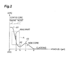
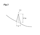
- Figs. 2 and 3 are drawings showing the index profile of the optical fiber 40 according to the present embodiment. Particularly, Fig. 3 is an enlarged view of region A enclosed in a dashed line in Fig. 2 .
- the optical fiber 40 according to the present embodiment has a center core 41 a center of which extends along a predetermined axis (optical axis AX), a side core 42 provided on an outer peripheral surface of the center core 41, and a cladding 43 provided on an outer peripheral surface of the side core 42.
- the center core 41 includes a ring part 410 having a projecting shape of relative index difference with respect to the refractive index of the cladding 43, along the radial direction.
- the foregoing index profile is defined by relative index differences ⁇ with respect to the refractive index of the cladding 43, of respective portions along a reference line perpendicular to the optical axis AX, as shown in Fig. 2 .
- Fig. 2 In the index profile of Fig.
- a region corresponding to the center core 41 is comprised of a peak part including a position where the relative index difference ⁇ is maximum (position with ⁇ 1), and a tail part, the tail part including a part in which the relative index difference decreases continuously from the peak part toward the cladding 43, and the ring part 410 having the discontinuously projecting shape of relative index difference.
- the shape of the ring part in the center core 41 is realized by sharply changing a doping amount of an index increase agent such as Ge, in manufacturing a preform with a profile shape consisting of a peak part, a tail part, and a ring part of a projecting shape included in the tail part (which is a preform for obtaining the optical fiber 40 by drawing), for example, by the VAD process, the MCVD process, or the like.
- an index increase agent such as Ge
- Structural parameters characterizing the index profile of the optical fiber 40 according to the present embodiment are defined as follows. With respect to the refractive index of the cladding 43, a maximum of the relative index difference in the peak part of the center core 41 is represented by ⁇ 1 [%], a minimum of the relative index difference between the center core 41 and the side core 42 by ⁇ 2 [%], and a maximum of the relative index difference in the side core 42 by ⁇ [%].
- a radius from the center of the center core 41 (agreeing with the optical axis AX) to the outside of the ring part 410 is represented by a [ ⁇ m], a radius from the center of the center core 41 to a position where the relative index difference is minimum between the center core 41 and the side core 42, by b [ ⁇ m], a radius from the center of the center core 41 to a position where the relative index difference is maximum in the side core 42, by c [ ⁇ m], and a radius from the center of the center core 41 to the outside of the side core 42 by d [ ⁇ m].
- the radii a and d are defined as positions where a derivative value of the relative index difference with respect to the radius r is negative and where an absolute value thereof becomes maximum.
- ⁇ ring [%] represents an increase of the relative index difference of the ring part with respect to a slope of the relative index difference of the tail part
- w [ ⁇ m] a width of the projecting part of the relative index difference (the width of the ring part).
- the optical fiber 40 of the present embodiment can have a wider tolerable range against variations of the structural parameters due to production variation, particularly, by setting c/a in an appropriate range.
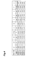
- Fig. 4 is a table showing a list of structures of optical fibers as Samples 1 to 4.
- Fig. 5 is a table showing a list of characteristics of the optical fibers as Samples 1 to 4.
- the optical fibers of Samples 1 to 4 have c/a set at 2.46, 2.41, 2.33, and 2.25, respectively, further satisfy Condition 1, and have the structural parameters including ⁇ 1, ⁇ 2, ⁇ 3, and a set so that the mode field diameter (MFD) becomes near 9.6 ⁇ m.
- MFD mode field diameter
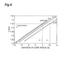
- Fig. 6 shows graphs showing changes of cable cutoff wavelength against variation of core radius of the respective optical fibers of Samples 1 to 4.
- Fig. 7 shows graphs showing changes of bending loss against variation of core radius of the respective optical fibers of Samples 1 to 4.
- Fig. 8 shows graphs showing changes of dispersion value at the wavelength 1530 nm against variation of ⁇ 1 of the respective optical fibers of Samples 1 to 4.
- the dispersion value at the wavelength of 1530 nm decreases with increase of ⁇ 1
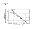
- Fig. 9 shows graphs showing changes of dispersion value at the wavelength 1565 nm against variation of ⁇ 1 of the respective optical fibers of Samples 1 to 4.
- the ratio c/a needs to be set in an appropriate range.
- the ratio c/a is preferably in the range of 2.25 to 2.50, more preferably in the range of 2.3 to 2.46, and still more preferably in the range of 2.33 to 2.41.
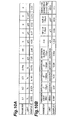
- Fig. 10A is a table showing a list of a structure of optical fibers of Sample 5.
- Fig. 10B is a table showing a list of characteristics of optical fibers of Sample 5.
- Fig. 11 shows graphs showing changes of cable cutoff wavelength against variation of core radius with the profile volume V of the ring part 410 being 0.0, 0.037, 0.073, and 0.110% ⁇ m 2 , in the optical fibers of Sample 5.
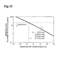
- Fig. 12 shows graphs showing changes of bending loss against variation of core radius with the profile volume V of the ring part 410 being 0.0,0.037, 0.073, and 0.110% ⁇ m 2 by change of ⁇ ring, in the optical fibers of Sample 5.
- the lower limit of variation of core radius for satisfying the bending loss ⁇ 20 dB/m in Condition 1 is about -3.4%, independent of V.
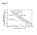
- Fig. 13 shows graphs showing changes of dispersion value at the wavelength 1530 nm against variation of ⁇ 1 with the profile volume V of the ring part 410 being 0.0, 0.037, 0.073, and 0.110% ⁇ m 2 by change of ⁇ ring, in the optical fibers of Sample 5.
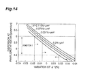
- Fig. 14 shows graphs showing changes of dispersion value at the wavelength 1565 nm against variation of ⁇ 1 with the profile volume V of the ring part 410 being 0.0, 0.037, 0.073, and 0.110% ⁇ m 2 by change of ⁇ ring, in the optical fibers of Sample 5.
- the tolerable range against production variation becomes wider with increase of the profile volume V of the ring part 410. It is, however, difficult in manufacture to achieve a considerable local increase of doping amount of Ge. It also raises concern of increase in transmission loss. Therefore, the profile volume V of the ring part 410 is preferably in the range of 0.0 to 0.11% ⁇ m 2 , more preferably in the range of 0.0 to 0.10% ⁇ m 2 , and still more preferably in the range of 0.012 to 0.075% ⁇ m 2 .
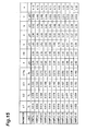
- Fig. 15 is a table showing a list of structures of optical fibers as Samples 6 to 16.
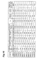
- Fig. 16 is a table showing a list of characteristics of the optical fibers as Samples 6 to 16. It is also easy to manufacture these optical fibers with desired characteristics at good yield.
- the index profile of the center core 41 in the optical fiber 40 of the present embodiment there are a variety of conceivable cases for the index profile of the center core 41 in the optical fiber 40 of the present embodiment.
- the value of ⁇ is preferably in the range of 3.2 to 6.0, in order to satisfy Condition 1 and maintain a wide tolerable range against variation of the structural parameters due to production variation.
- ⁇ r ⁇ ⁇ 1 1 - r / a ⁇
- Fig. 17 is a drawing showing a configuration example of an optical communication system 20 using the optical fiber 40 of the present embodiment.
- the optical communication system 20 is provided with a transmitter 31, a repeater 32, a repeater 33, and a receiver 34 and with the optical fiber 40 of the present embodiment as a transmission path to transmit signal light between the repeater 32 and the repeater 33.
- Each of the repeaters 32 and 33 includes an optical amplifier to amply the signal light.
- Each of the repeaters 32 and 33 preferably includes a dispersion compensating optical fiber.
Landscapes
- Physics & Mathematics (AREA)
- Chemical & Material Sciences (AREA)
- Dispersion Chemistry (AREA)
- General Physics & Mathematics (AREA)
- Optics & Photonics (AREA)
- Optical Fibers, Optical Fiber Cores, And Optical Fiber Bundles (AREA)
Abstract
Description
- The present invention relates to an optical fiber and an optical communication system including the same.
- A non-zero dispersion-shifted fiber (NZDSF) is known as an optical fiber used as a signal light transmission path in an optical communication system. NZDSF has positive chromatic dispersion and small but non-zero absolute values of chromatic dispersion in the entire range of the C-band (wavelengths of 1530 to 1565 nm) and the L-band (wavelengths of 1565 to 1625 nm).
- It is expected that such NZDSF has the preferred characteristics as described in
Non-patent Document 1, as to the chromatic dispersion, dispersion slope, mode field diameter, effective area, cable cutoff wavelength, bending loss, and so on.Patent Document 1 andPatent Document 2 disclose the optical fibers having such preferred characteristics. - The optical fiber disclosed in
Patent Document 1 has a core consisting of three segments. The three segments consist of a first segment with an α-power index profile, and a second segment and a third segment provided around the first segment and each having a step index profile. The optical fiber disclosed inPatent Document 2 consists of a center core, a first ring provided on the outer periphery of the center core, a second ring provided on the outer periphery of the first ring and having the refractive index lower than the center core and higher than the first ring, a third ring part provided on the outer periphery of the second ring and having the refractive index higher than a cladding, and the cladding provided on the outer periphery of the third ring part. -
- Patent Document 1: Japanese Patent No.
4393708 - Patent Document 2: Japanese Patent Application Laid-Open No.
10-293225 - Non-patent Document 1: LEAF Optical Fiber Catalog, Corning Incorporated
- The inventor investigated the conventional optical fibers and found the following problem. Namely, the structures of the optical fibers disclosed in
Patent Document 1 andPatent Document 2 above had narrow tolerable ranges of structural parameters due to production variation and it was difficult to manufacture the optical fibers with desired characteristics at good yield. - The present invention has been accomplished in order to solve the above problem and it is an object of the present invention to provide an optical fiber with a structure capable of readily achieving desired characteristics without reduction of production yield and an optical communication system including the optical fiber.
- In order to achieve the above object, an optical fiber according to the present invention, as a first aspect, comprises a center core a center of which extends along a predetermined axis, a side core provided on an outer peripheral surface of the center core, and a cladding provided on an outer peripheral surface of the side core. In the optical fiber of the first aspect, the center core has a peak part, and a tail part including a ring part. Specifically, in an index profile defined by relative index differences with respect to a refractive index of the cladding, of respective portions along a reference line perpendicular to the predetermined axis, the peak part is a region including a position where the relative index difference is maximum. The tail part excluding the ring part is a region where the relative index difference decreases continuously from the peak part toward the cladding, and the ring part included in the tail part is a region having a discontinuously projecting shape of the relative index difference in the tail part.
- Furthermore, in a first embodiment, when a is a radius along the reference line from the center of the center core to an outside of the ring part and c is a radius along the reference line from the center of the center core to a position where the relative index difference is maximum in the side core, the index profile is characterized by having a shape in which c/a is in the range of 2.25 to 2.50, so as to realize a first dispersion value in the range of 2.0 to 5.5 ps/nm/km at the wavelength of 1530 nm, a second dispersion value in the range of 4.5 to 6.0 ps/nm/km at the wavelength of 1565 nm, a third dispersion value in the range of 8.5 to 11.2 ps/nm/km at the wavelength of 1625 nm, a cable cutoff wavelength in the range of not more than 1.45 µm, a bending loss in the diameter of 20 mm in the range of not more than 20 dB/m at the wavelength of 1550 nm, and an effective area in the range of 64 to 75 µm2 at the wavelength of 1550 nm.
- As a second aspect applicable to the first aspect, preferably, a maximum Δ1 of the relative index difference in the peak part is in the range of 0.55 to 0.70%, a minimum Δ2 of the relative index difference between the center core and the side core is in the range of 0.0 to 0.10%, a maximum Δ3 of the relative index difference in the side core is in the range of 0.14 to 0.21%, and the radius a is in the range of 2.0 to 3.0 µm.
- As a third aspect applicable to at least either of the first and second aspects, a profile volume V of the ring part, which is defined by the formula below, is preferably more than 0%·µm2 and not more than 0.11%·µm2, where w is a width of the ring part along the reference line, r a radius from the center of the center core, and Δ(r) an index profile with respect to the radius r as a variable.

- As a fourth aspect applicable to at least any one of the first to third aspects, preferably, an increase Δring of the relative index difference in the ring part is more than 0% and not more than 0.6%, and a width w of the ring part along the reference line is more than 0.0 µm and not more than 0.5 µm.
- As a fifth aspect applicable to at least any one of the first to fourth aspects, preferably, a radius b from the center of the center core to a position where the relative index difference is minimum between the center core and the side core is in the range of 3.0 to 5.0 µm and a radius d from the center of the center core to an outside of the side core is in the range of 7.0 to 10.0 µm.
- As a sixth aspect applicable to at least any one of the first to fifth aspects, preferably, an index profile of the center core except for the ring part is an α-power profile and, more specifically, a value of α is in the range of 3.3 to 6.0.
- An optical communication system according to the present invention comprises the optical fiber according to at least any one of the first to sixth aspects.
- The optical fiber according to the present invention readily achieves the desired characteristics without reduction of production yield.
-
-
Fig. 1 is a drawing showing a sectional structure of an optical fiber according to an embodiment of the present invention; -
Fig. 2 is a drawing showing an index profile of the optical fiber according to the embodiment: -
Fig. 3 is a drawing showing the index profile of the optical fiber according to the embodiment; -
Fig. 4 is a table showing a list of structures ofSamples 1 to 4 of optical fibers according to the embodiment: -
Fig. 5 is a table showing a list of characteristics of the optical fibers ofSamples 1 to 4; -
Fig. 6 shows graphs showing changes of cable cutoff wavelength against variation of core radius of the respective optical fibers ofSamples 1 to 4; -
Fig. 7 shows graphs showing changes of bending loss against variation of core radius of the respective optical fibers ofSamples 1 to 4; -
Fig. 8 shows graphs showing changes of dispersion value at thewavelength 1530 nm against variation of Δ1 of the respective optical fibers ofSamples 1 to 4; -
Fig. 9 shows graphs showing changes of dispersion value at thewavelength 1565 nm against variation of Δ1 of the respective optical fibers ofSamples 1 to 4; -
Figs. 10A and 10B are tables showing respective lists of a structure and characteristics of optical fibers ofSample 5; -
Fig. 11 shows graphs showing changes of cable cutoff wavelength against variation of core radius with Δring being 0.0, 0.2, 0.4, and 0.6%, in the optical fibers ofSample 5; -
Fig. 12 shows graphs showing changes of bending loss against variation of core radius with Δring being 0.0, 0.2, 0.4, and 0.6%, in the optical fibers ofSample 5; -
Fig. 13 shows graphs showing changes of dispersion value at thewavelength 1530 nm against variation of Δ1 with Δring being 0.0, 0.2, 0.4, and 0.6%, in the optical fibers ofSample 5; -
Fig. 14 shows graphs showing changes of dispersion value at thewavelength 1565 nm against variation of Δ1 with Δring being 0.0, 0.2, 0.4, and 0.6%, in the optical fibers ofSample 5; -
Fig. 15 is a table showing a list of structures ofSamples 6 to 16 of optical fibers according to the embodiment; -
Fig. 16 is a table showing a list of characteristics of the optical fibers ofSamples 6 to 16; and -
Fig. 17 is a drawing showing a configuration example of an optical communication system using the optical fiber of the embodiment. - Embodiments of the present invention will be described below in detail with reference to the accompanying drawings. The same elements will be denoted by the same reference signs in the description of the drawings, without redundant description.
- A non-zero dispersion-shifted fiber (NZDSF) used as a signal light transmission path in an optical communication system has positive chromatic dispersion and small but non-zero absolute values of chromatic dispersion in the entire range of the C-band and the L-band. The optical fiber of this kind desirably has the characteristics (a) to (h) below. In the description hereinafter, these characteristics (a) to (h) will be referred to as "
Condition 1." - (a) Chromatic dispersion at the wavelength of 1530 nm (first dispersion value): 2.0-5.5 ps/nm/km
- (b) Chromatic dispersion at the wavelength of 1565 nm (second dispersion value): 4.5-6.0 ps/nm/km
- (c) Chromatic dispersion at the wavelength of 1625 nm (third dispersion value): 8.5-11.2 ps/nm/km
- (d) Dispersion slope at the wavelength of 1550 nm: 0.090 or less ps/nm2/km
- (e) Mode field diameter (MFD) at the wavelength of 1550 nm: 9.2-10.0 µm
- (f) Effective area (Aeff) at the wavelength of 1550 nm: 64 or more µm2
- (g) Cable cutoff wavelength (λcc): 1450 or less nm
- (h) Bending loss in the diameter of 20 mm at the wavelength of 1550 nm: 20 or less dB/m
-
Fig. 1 is a drawing showing a sectional structure of anoptical fiber 40 according to an embodiment of the present invention and theoptical fiber 40 according to the present embodiment has an indexprofile satisfying Condition 1 above.Figs. 2 and3 are drawings showing the index profile of theoptical fiber 40 according to the present embodiment. Particularly,Fig. 3 is an enlarged view of region A enclosed in a dashed line inFig. 2 . Theoptical fiber 40 according to the present embodiment has a center core 41 a center of which extends along a predetermined axis (optical axis AX), aside core 42 provided on an outer peripheral surface of thecenter core 41, and acladding 43 provided on an outer peripheral surface of theside core 42. Thecenter core 41 includes aring part 410 having a projecting shape of relative index difference with respect to the refractive index of thecladding 43, along the radial direction. The foregoing index profile is defined by relative index differences Δ with respect to the refractive index of thecladding 43, of respective portions along a reference line perpendicular to the optical axis AX, as shown inFig. 2 . In the index profile ofFig. 2 , therefore, a region corresponding to thecenter core 41 is comprised of a peak part including a position where the relative index difference Δ is maximum (position with Δ1), and a tail part, the tail part including a part in which the relative index difference decreases continuously from the peak part toward thecladding 43, and thering part 410 having the discontinuously projecting shape of relative index difference. - The shape of the ring part in the
center core 41 is realized by sharply changing a doping amount of an index increase agent such as Ge, in manufacturing a preform with a profile shape consisting of a peak part, a tail part, and a ring part of a projecting shape included in the tail part (which is a preform for obtaining theoptical fiber 40 by drawing), for example, by the VAD process, the MCVD process, or the like. - Structural parameters characterizing the index profile of the
optical fiber 40 according to the present embodiment are defined as follows. With respect to the refractive index of thecladding 43, a maximum of the relative index difference in the peak part of thecenter core 41 is represented by Δ1 [%], a minimum of the relative index difference between thecenter core 41 and theside core 42 by Δ2 [%], and a maximum of the relative index difference in theside core 42 by Δ [%]. A radius from the center of the center core 41 (agreeing with the optical axis AX) to the outside of thering part 410 is represented by a [µm], a radius from the center of thecenter core 41 to a position where the relative index difference is minimum between thecenter core 41 and theside core 42, by b [µm], a radius from the center of thecenter core 41 to a position where the relative index difference is maximum in theside core 42, by c [µm], and a radius from the center of thecenter core 41 to the outside of theside core 42 by d [µm]. If the index profile gently changes with the radius r from the optical axis AX, the radii a and d are defined as positions where a derivative value of the relative index difference with respect to the radius r is negative and where an absolute value thereof becomes maximum. As shown inFig. 3 , Δring [%] represents an increase of the relative index difference of the ring part with respect to a slope of the relative index difference of the tail part, and w [µm] a width of the projecting part of the relative index difference (the width of the ring part). - The
optical fiber 40 of the present embodiment can have a wider tolerable range against variations of the structural parameters due to production variation, particularly, by setting c/a in an appropriate range. -
Fig. 4 is a table showing a list of structures of optical fibers asSamples 1 to 4.Fig. 5 is a table showing a list of characteristics of the optical fibers asSamples 1 to 4. The optical fibers ofSamples 1 to 4 have c/a set at 2.46, 2.41, 2.33, and 2.25, respectively, further satisfyCondition 1, and have the structural parameters including Δ1, Δ2, Δ3, and a set so that the mode field diameter (MFD) becomes near 9.6 µm. -
Fig. 6 shows graphs showing changes of cable cutoff wavelength against variation of core radius of the respective optical fibers ofSamples 1 to 4. As can be seen fromFig. 6 , the cable cutoff wavelength (λcc) increases with increase in core radius, and the upper limit of the variation of core radius for satisfying λcc ≤ 1.45 µm inCondition 1 is 10.1% in the case of c/a = 2.25 and 4.8% in the case of c/a = 2.46. -
Fig. 7 shows graphs showing changes of bending loss against variation of core radius of the respective optical fibers ofSamples 1 to 4. As can be seen fromFig. 7 , the bending loss increases with decrease in core radius, and the lower limit of the variation of core radius for satisfying the bending loss ≤ 20 dB/m inCondition 1 is -8.6% in the case of c/a = 2.25 and -2.0% in the case of c/a = 2.46. - Therefore, it is found from the graphs of
Figs. 6 and7 that tolerances of variation of core radius for satisfyingCondition 1 are -8.6% to 10.1% in the case of c/a = 2.25 and -2.0% to 4.8% in the case of c/a = 2.46. The tolerable range against variation of core radius becomes wider with decrease of c/a. All the fiber characteristics vary with variation in core radius, and the severest tolerable range is that for the conditions of λcc and the bending loss. -
Fig. 8 shows graphs showing changes of dispersion value at thewavelength 1530 nm against variation of Δ1 of the respective optical fibers ofSamples 1 to 4. As can be seen fromFig. 8 , the dispersion value at the wavelength of 1530 nm decreases with increase of Δ1, and the upper limit of variation of Δ1 for satisfying the preferred range of dispersion at the wavelength of 1530 nm of 2.0 to 5.5 ps/nm/km inCondition 1 is 0.009% in the case of c/a = 2.25 and 0.011% in the case of c/a = 2.46. -
Fig. 9 shows graphs showing changes of dispersion value at thewavelength 1565 nm against variation of Δ1 of the respective optical fibers ofSamples 1 to 4. As can be seen fromFig. 9 , the dispersion value at the wavelength of 1565 nm increases with decrease of Δ1, and the lower limit of variation of Δ1 for satisfying the preferred range of dispersion at the wavelength of 1565 nm of 4.5 to 6.0 ps/nm/km inCondition 1 is -0.012% in the case of c/a = 2.25 and -0.020% in the case of c/a = 2.46. - Therefore, it is found from the graphs of
Figs. 8 and9 that the tolerances of variation of Δ1 for satisfyingCondition 1 are -0.012 to 0.009% in the case of c/a = 2.25 and -0.020 to 0.011% in the case of c/a = 2.46. The tolerable range against variation of Δ1 becomes wider with increase of c/a. All the fiber characteristics vary with variation of Δ1, and the severest condition for satisfyingCondition 1 is the condition for dispersion at the wavelengths of 1530 nm and 1565 nm. - It is confirmed by the above results that the tolerable range against variation of either the core radius or Δ1 becomes narrower with the ratio c/a being too large or too small. In order to ensure a wide tolerable range against overall structural parameter variation due to production variation, therefore, the ratio c/a needs to be set in an appropriate range. The ratio c/a is preferably in the range of 2.25 to 2.50, more preferably in the range of 2.3 to 2.46, and still more preferably in the range of 2.33 to 2.41.
-
Fig. 10A is a table showing a list of a structure of optical fibers ofSample 5.Fig. 10B is a table showing a list of characteristics of optical fibers ofSample 5. -
Fig. 11 shows graphs showing changes of cable cutoff wavelength against variation of core radius with the profile volume V of thering part 410 being 0.0, 0.037, 0.073, and 0.110%·µm2, in the optical fibers ofSample 5. As can be seen fromFig. 11 , the upper limit of variation of core radius for satisfying λcc ≤ 1.45 µm inCondition 1 is 7.5% in the case of V = 0.0%·µm2 and 9.4% in the case of V = 0.110%·µm2, -
Fig. 12 shows graphs showing changes of bending loss against variation of core radius with the profile volume V of thering part 410 being 0.0,0.037, 0.073, and 0.110%·µm2 by change of Δring, in the optical fibers ofSample 5. As can be seen fromFig. 12 , the lower limit of variation of core radius for satisfying the bending loss ≤ 20 dB/m inCondition 1 is about -3.4%, independent of V. - Therefore, it is confirmed by the graphs of
Figs. 11 and12 that the tolerances of variation of core radius for satisfyingCondition 1 are -3.4 to 7.5% in the case of V = 0.0%·µm2 and -3.4 to 9.4% in the case of V = 0.110%·µm2. The tolerable range against variation of core radius becomes wider with increase of V. - Furthermore,
Fig. 13 shows graphs showing changes of dispersion value at thewavelength 1530 nm against variation of Δ1 with the profile volume V of thering part 410 being 0.0, 0.037, 0.073, and 0.110%·µm2 by change of Δring, in the optical fibers ofSample 5. As can be seen fromFig. 13 , the upper limit of variation of Δ1 for satisfying the preferred range of dispersion at the wavelength of 1530 nm of 2.0 to 5.5 ps/nm/km inCondition 1 is 0.007% in the case of V = 0.0%·µm2 and 0.023% in the case of V = 0.110%·µm2. -
Fig. 14 shows graphs showing changes of dispersion value at thewavelength 1565 nm against variation of Δ1 with the profile volume V of thering part 410 being 0.0, 0.037, 0.073, and 0.110%·µm2 by change of Δring, in the optical fibers ofSample 5. As can be seen fromFig. 14 , the range of variation of Δ1 for satisfying the preferred range of dispersion at thewavelength 1565 nm of 4.5 to 6.0 ps/nm/km inCondition 1 is -0.017 to 0.017% in the case of V = 0.0%·µm2 and -0.007 to 0.032% in the case of V = 0.110%·µm2. - Therefore, it is confirmed by the graphs of
Figs. 13 and14 that the tolerances of variation of Δ1 for satisfyingCondition 1 are -0.017 to 0.007% in the case of V = 0.0%·µm2 and -0.007 to 0.023% in the case of V = 0.110%·µm2. The tolerable range against variation of Δ1 also becomes wider with increase of V. - Namely, the tolerable range against production variation becomes wider with increase of the profile volume V of the
ring part 410. It is, however, difficult in manufacture to achieve a considerable local increase of doping amount of Ge. It also raises concern of increase in transmission loss. Therefore, the profile volume V of thering part 410 is preferably in the range of 0.0 to 0.11%·µm2, more preferably in the range of 0.0 to 0.10%·µm2, and still more preferably in the range of 0.012 to 0.075%·µm2. -
Fig. 15 is a table showing a list of structures of optical fibers asSamples 6 to 16.Fig. 16 is a table showing a list of characteristics of the optical fibers asSamples 6 to 16. It is also easy to manufacture these optical fibers with desired characteristics at good yield. - There are a variety of conceivable cases for the index profile of the
center core 41 in theoptical fiber 40 of the present embodiment. When the index profile Δ(r) of the region within the radius a of thecenter core 41 except for thering part 410 is approximated by the below formula, the value of α is preferably in the range of 3.2 to 6.0, in order to satisfyCondition 1 and maintain a wide tolerable range against variation of the structural parameters due to production variation.
-
Fig. 17 is a drawing showing a configuration example of anoptical communication system 20 using theoptical fiber 40 of the present embodiment. Theoptical communication system 20 is provided with atransmitter 31, arepeater 32, arepeater 33, and areceiver 34 and with theoptical fiber 40 of the present embodiment as a transmission path to transmit signal light between therepeater 32 and therepeater 33. Each of therepeaters repeaters - 20 ... optical communication system; 31 ... transmitter; 32, 33 ... repeaters; 34 ... receiver; 40 ... optical fiber; 41 ... center core; 42 ... side core; 43 ... cladding; and 410 ... ring part.
Claims (7)
- An optical fiber comprising a center core a center of which extends along a predetermined axis, a side core provided on an outer peripheral surface of the center core, and a cladding provided on an outer peripheral surface of the side core,
wherein in an index profile defined by relative index differences with respect to a refractive index of the cladding, of respective portions along a reference line perpendicular to the predetermined axis, a region corresponding to the center core has a peak part including a position where the relative index difference is maximum, and a tail part, the tail part including a part in which the relative index difference decreases continuously from the peak part toward the cladding, and a ring part having a discontinuously projecting shape of the relative index difference,
wherein when a is a radius along the reference line from the center of the center core to an outside of the ring part and c is a radius along the reference line from the center of the center core to a position where the relative index difference is maximum in the side core, the index profile has a shape in which c/a is in the range of 2.25 to 2.50,
so as to realize a first dispersion value in the range of 2.0 to 5.5 ps/nm/km at the wavelength of 1530 nm, a second dispersion value in the range of 4.5 to 6.0 ps/nm/km at the wavelength of 1565 nm, a third dispersion value in the range of 8.5 to 11.2 ps/nm/km at the wavelength of 1625 nm, a cable cutoff wavelength in the range of not more than 1.45 µm, a bending loss in the diameter of 20 mm in the range of not more than 20 dB/m at the wavelength of 1550 nm, and an effective area in the range of 64 to 75 µm2 at the wavelength of 1550 nm. - The optical fiber according to claim 1, wherein a maximum Δ1 of the relative index difference in the peak part is in the range of 0.55 to 0.70%,
wherein a minimum Δ2 of the relative index difference between the center core and the side core is in the range of 0.0 to 0.10%,
wherein a maximum Δ3 of the relative index difference in the side core is in the range of 0.14 to 0.21%, and
wherein the radius a is in the range of 2.0 to 3.0 µm. - The optical fiber according to claim 1 or 2, wherein a profile volume V of the ring part, which is defined by the following formula,

is more than 0%·µm2 and not more than 0.11%·µm2, where w is a width of the ring part along the reference line, r a radius from the center of the center core, and Δ(r) an index profile with respect to the radius r as a variable. - The optical fiber according to any one of claims 1 to 3, wherein an increase Δring of the relative index difference in the ring part is more than 0% and not more than 0.6%, and
wherein a width w of the ring part along the reference line is more than 0.0 µm and not more than 0.5 µm. - The optical fiber according to any one of claims 1 to 5, wherein a radius b from the center of the center core to a position where the relative index difference is minimum between the center core and the side core is in the range of 3.0 to 5.0 µm, and
wherein a radius d from the center of the center core to an outside of the side core is in the range of 7.0 to 10.0 µm. - The optical fiber according to any one of claims 1 to 5, wherein an index profile of the center core except for the ring part is an α-power profile and a value of α is in the range of 3.3 to 6.0.
- An optical communication system comprising the optical fiber as defined in any one of claims 1 to 6, as a signal transmission path.
Applications Claiming Priority (2)
| Application Number | Priority Date | Filing Date | Title |
|---|---|---|---|
| JP2012041335A JP5887999B2 (en) | 2012-02-28 | 2012-02-28 | Optical fiber |
| PCT/JP2013/052754 WO2013129050A1 (en) | 2012-02-28 | 2013-02-06 | Optical fiber and optical communication system containing same |
Publications (3)
| Publication Number | Publication Date |
|---|---|
| EP2821822A1 true EP2821822A1 (en) | 2015-01-07 |
| EP2821822A4 EP2821822A4 (en) | 2015-10-21 |
| EP2821822B1 EP2821822B1 (en) | 2018-11-21 |
Family
ID=49082254
Family Applications (1)
| Application Number | Title | Priority Date | Filing Date |
|---|---|---|---|
| EP13754773.3A Active EP2821822B1 (en) | 2012-02-28 | 2013-02-06 | Optical fiber and optical communication system containing same |
Country Status (6)
| Country | Link |
|---|---|
| US (1) | US8903213B2 (en) |
| EP (1) | EP2821822B1 (en) |
| JP (1) | JP5887999B2 (en) |
| CN (1) | CN104136951B (en) |
| DK (1) | DK2821822T3 (en) |
| WO (1) | WO2013129050A1 (en) |
Cited By (1)
| Publication number | Priority date | Publication date | Assignee | Title |
|---|---|---|---|---|
| US10094976B2 (en) | 2015-02-12 | 2018-10-09 | Fujikura Ltd. | Dispersion shifted optical fiber |
Family Cites Families (9)
| Publication number | Priority date | Publication date | Assignee | Title |
|---|---|---|---|---|
| JP3408713B2 (en) | 1997-04-21 | 2003-05-19 | 株式会社フジクラ | Dispersion shifted optical fiber |
| US6031956A (en) * | 1997-11-17 | 2000-02-29 | Corning Incorporated | High performance single mode waveguide |
| US6212322B1 (en) * | 1998-09-11 | 2001-04-03 | Corning Incorporated | Positive dispersion low dispersion slope fiber |
| US6768852B2 (en) * | 2001-07-11 | 2004-07-27 | Corning Incorporated | Dispersion and slope compensating optical fiber and transmission link including same |
| EP1530735A1 (en) * | 2002-07-31 | 2005-05-18 | Corning Incorporated | Non-zero dispersion shifted optical fiber having large effective area, low slope and low zero dispersion |
| CN1667439A (en) * | 2004-10-15 | 2005-09-14 | 中国科学院长春光学精密机械与物理研究所 | Big mode field optical fiber |
| CN101169497A (en) * | 2006-10-23 | 2008-04-30 | 汪业衡 | Full-wave nonzero dispersion flat single-mode optical fiber |
| US20090169163A1 (en) * | 2007-12-13 | 2009-07-02 | Abbott Iii John Steele | Bend Resistant Multimode Optical Fiber |
| CN101840022A (en) * | 2010-04-02 | 2010-09-22 | 哈尔滨工程大学 | Ring-shaped distributed multi-core fiber and preparation method thereof |
-
2012
- 2012-02-28 JP JP2012041335A patent/JP5887999B2/en active Active
-
2013
- 2013-02-06 WO PCT/JP2013/052754 patent/WO2013129050A1/en not_active Ceased
- 2013-02-06 DK DK13754773.3T patent/DK2821822T3/en active
- 2013-02-06 EP EP13754773.3A patent/EP2821822B1/en active Active
- 2013-02-06 CN CN201380011007.7A patent/CN104136951B/en active Active
- 2013-02-20 US US13/771,745 patent/US8903213B2/en active Active
Cited By (1)
| Publication number | Priority date | Publication date | Assignee | Title |
|---|---|---|---|---|
| US10094976B2 (en) | 2015-02-12 | 2018-10-09 | Fujikura Ltd. | Dispersion shifted optical fiber |
Also Published As
| Publication number | Publication date |
|---|---|
| JP2013178335A (en) | 2013-09-09 |
| CN104136951A (en) | 2014-11-05 |
| US8903213B2 (en) | 2014-12-02 |
| JP5887999B2 (en) | 2016-03-16 |
| WO2013129050A1 (en) | 2013-09-06 |
| EP2821822A4 (en) | 2015-10-21 |
| US20140064685A1 (en) | 2014-03-06 |
| EP2821822B1 (en) | 2018-11-21 |
| DK2821822T3 (en) | 2019-01-14 |
| CN104136951B (en) | 2017-05-10 |
Similar Documents
| Publication | Publication Date | Title |
|---|---|---|
| EP2211211B1 (en) | Single mode optical fibre | |
| JP5379396B2 (en) | Transmission optical fiber with large effective area | |
| US6483975B1 (en) | Positive dispersion optical fiber having large effective area | |
| EP2894498B1 (en) | Optical fiber | |
| EP1266252A2 (en) | Dispersion slope compensating optical fiber | |
| JPWO2008093870A1 (en) | Optical transmission system and dispersion compensating optical fiber | |
| CN114153021A (en) | Non-Zero Dispersion Shifted Fiber with Low Dispersion Slope and Large Effective Area | |
| EP1565774A1 (en) | Dispersion compensating optical fiber for smf and transmission link including same | |
| EP2821822B1 (en) | Optical fiber and optical communication system containing same | |
| US7164832B2 (en) | Optical fiber and optical communication system employing the optical fiber | |
| JP3932246B2 (en) | Waveguide fiber with high zero dispersion. | |
| US10094976B2 (en) | Dispersion shifted optical fiber | |
| EP1259840B1 (en) | Optical fiber for wdm transmission | |
| WO2007005332A2 (en) | Non-zero dispersion shifted optical fiber | |
| CN101498811A (en) | Dispersion compensating fiber with high dispersion factor | |
| JP3756389B2 (en) | Dispersion compensating optical fiber and optical fiber composite transmission line | |
| JP4205455B2 (en) | Optical fiber and optical transmission system using the same | |
| JP3766073B2 (en) | Dispersion compensating optical fiber and optical fiber composite transmission line | |
| JP2005003794A (en) | Optical fiber and optical transmission line using the same | |
| CN116880004A (en) | Low-attenuation few-mode optical fiber |
Legal Events
| Date | Code | Title | Description |
|---|---|---|---|
| PUAI | Public reference made under article 153(3) epc to a published international application that has entered the european phase |
Free format text: ORIGINAL CODE: 0009012 |
|
| 17P | Request for examination filed |
Effective date: 20140617 |
|
| AK | Designated contracting states |
Kind code of ref document: A1 Designated state(s): AL AT BE BG CH CY CZ DE DK EE ES FI FR GB GR HR HU IE IS IT LI LT LU LV MC MK MT NL NO PL PT RO RS SE SI SK SM TR |
|
| AX | Request for extension of the european patent |
Extension state: BA ME |
|
| DAX | Request for extension of the european patent (deleted) | ||
| RA4 | Supplementary search report drawn up and despatched (corrected) |
Effective date: 20150921 |
|
| RIC1 | Information provided on ipc code assigned before grant |
Ipc: G02B 6/028 20060101ALI20150915BHEP Ipc: G02B 6/02 20060101ALI20150915BHEP Ipc: G02B 6/036 20060101AFI20150915BHEP |
|
| GRAP | Despatch of communication of intention to grant a patent |
Free format text: ORIGINAL CODE: EPIDOSNIGR1 |
|
| STAA | Information on the status of an ep patent application or granted ep patent |
Free format text: STATUS: GRANT OF PATENT IS INTENDED |
|
| INTG | Intention to grant announced |
Effective date: 20180719 |
|
| GRAS | Grant fee paid |
Free format text: ORIGINAL CODE: EPIDOSNIGR3 |
|
| GRAA | (expected) grant |
Free format text: ORIGINAL CODE: 0009210 |
|
| STAA | Information on the status of an ep patent application or granted ep patent |
Free format text: STATUS: THE PATENT HAS BEEN GRANTED |
|
| AK | Designated contracting states |
Kind code of ref document: B1 Designated state(s): AL AT BE BG CH CY CZ DE DK EE ES FI FR GB GR HR HU IE IS IT LI LT LU LV MC MK MT NL NO PL PT RO RS SE SI SK SM TR |
|
| REG | Reference to a national code |
Ref country code: CH Ref legal event code: EP |
|
| REG | Reference to a national code |
Ref country code: IE Ref legal event code: FG4D |
|
| REG | Reference to a national code |
Ref country code: DE Ref legal event code: R096 Ref document number: 602013047129 Country of ref document: DE |
|
| REG | Reference to a national code |
Ref country code: AT Ref legal event code: REF Ref document number: 1068222 Country of ref document: AT Kind code of ref document: T Effective date: 20181215 |
|
| REG | Reference to a national code |
Ref country code: DK Ref legal event code: T3 Effective date: 20190106 |
|
| REG | Reference to a national code |
Ref country code: NL Ref legal event code: FP |
|
| REG | Reference to a national code |
Ref country code: AT Ref legal event code: MK05 Ref document number: 1068222 Country of ref document: AT Kind code of ref document: T Effective date: 20181121 |
|
| PG25 | Lapsed in a contracting state [announced via postgrant information from national office to epo] |
Ref country code: LT Free format text: LAPSE BECAUSE OF FAILURE TO SUBMIT A TRANSLATION OF THE DESCRIPTION OR TO PAY THE FEE WITHIN THE PRESCRIBED TIME-LIMIT Effective date: 20181121 Ref country code: BG Free format text: LAPSE BECAUSE OF FAILURE TO SUBMIT A TRANSLATION OF THE DESCRIPTION OR TO PAY THE FEE WITHIN THE PRESCRIBED TIME-LIMIT Effective date: 20190221 Ref country code: NO Free format text: LAPSE BECAUSE OF FAILURE TO SUBMIT A TRANSLATION OF THE DESCRIPTION OR TO PAY THE FEE WITHIN THE PRESCRIBED TIME-LIMIT Effective date: 20190221 Ref country code: AT Free format text: LAPSE BECAUSE OF FAILURE TO SUBMIT A TRANSLATION OF THE DESCRIPTION OR TO PAY THE FEE WITHIN THE PRESCRIBED TIME-LIMIT Effective date: 20181121 Ref country code: HR Free format text: LAPSE BECAUSE OF FAILURE TO SUBMIT A TRANSLATION OF THE DESCRIPTION OR TO PAY THE FEE WITHIN THE PRESCRIBED TIME-LIMIT Effective date: 20181121 Ref country code: IS Free format text: LAPSE BECAUSE OF FAILURE TO SUBMIT A TRANSLATION OF THE DESCRIPTION OR TO PAY THE FEE WITHIN THE PRESCRIBED TIME-LIMIT Effective date: 20190321 Ref country code: ES Free format text: LAPSE BECAUSE OF FAILURE TO SUBMIT A TRANSLATION OF THE DESCRIPTION OR TO PAY THE FEE WITHIN THE PRESCRIBED TIME-LIMIT Effective date: 20181121 Ref country code: LV Free format text: LAPSE BECAUSE OF FAILURE TO SUBMIT A TRANSLATION OF THE DESCRIPTION OR TO PAY THE FEE WITHIN THE PRESCRIBED TIME-LIMIT Effective date: 20181121 Ref country code: FI Free format text: LAPSE BECAUSE OF FAILURE TO SUBMIT A TRANSLATION OF THE DESCRIPTION OR TO PAY THE FEE WITHIN THE PRESCRIBED TIME-LIMIT Effective date: 20181121 |
|
| PG25 | Lapsed in a contracting state [announced via postgrant information from national office to epo] |
Ref country code: RS Free format text: LAPSE BECAUSE OF FAILURE TO SUBMIT A TRANSLATION OF THE DESCRIPTION OR TO PAY THE FEE WITHIN THE PRESCRIBED TIME-LIMIT Effective date: 20181121 Ref country code: SE Free format text: LAPSE BECAUSE OF FAILURE TO SUBMIT A TRANSLATION OF THE DESCRIPTION OR TO PAY THE FEE WITHIN THE PRESCRIBED TIME-LIMIT Effective date: 20181121 Ref country code: AL Free format text: LAPSE BECAUSE OF FAILURE TO SUBMIT A TRANSLATION OF THE DESCRIPTION OR TO PAY THE FEE WITHIN THE PRESCRIBED TIME-LIMIT Effective date: 20181121 Ref country code: GR Free format text: LAPSE BECAUSE OF FAILURE TO SUBMIT A TRANSLATION OF THE DESCRIPTION OR TO PAY THE FEE WITHIN THE PRESCRIBED TIME-LIMIT Effective date: 20190222 Ref country code: PT Free format text: LAPSE BECAUSE OF FAILURE TO SUBMIT A TRANSLATION OF THE DESCRIPTION OR TO PAY THE FEE WITHIN THE PRESCRIBED TIME-LIMIT Effective date: 20190321 |
|
| PG25 | Lapsed in a contracting state [announced via postgrant information from national office to epo] |
Ref country code: PL Free format text: LAPSE BECAUSE OF FAILURE TO SUBMIT A TRANSLATION OF THE DESCRIPTION OR TO PAY THE FEE WITHIN THE PRESCRIBED TIME-LIMIT Effective date: 20181121 Ref country code: IT Free format text: LAPSE BECAUSE OF FAILURE TO SUBMIT A TRANSLATION OF THE DESCRIPTION OR TO PAY THE FEE WITHIN THE PRESCRIBED TIME-LIMIT Effective date: 20181121 Ref country code: CZ Free format text: LAPSE BECAUSE OF FAILURE TO SUBMIT A TRANSLATION OF THE DESCRIPTION OR TO PAY THE FEE WITHIN THE PRESCRIBED TIME-LIMIT Effective date: 20181121 |
|
| REG | Reference to a national code |
Ref country code: DE Ref legal event code: R097 Ref document number: 602013047129 Country of ref document: DE |
|
| PG25 | Lapsed in a contracting state [announced via postgrant information from national office to epo] |
Ref country code: RO Free format text: LAPSE BECAUSE OF FAILURE TO SUBMIT A TRANSLATION OF THE DESCRIPTION OR TO PAY THE FEE WITHIN THE PRESCRIBED TIME-LIMIT Effective date: 20181121 Ref country code: SM Free format text: LAPSE BECAUSE OF FAILURE TO SUBMIT A TRANSLATION OF THE DESCRIPTION OR TO PAY THE FEE WITHIN THE PRESCRIBED TIME-LIMIT Effective date: 20181121 Ref country code: SK Free format text: LAPSE BECAUSE OF FAILURE TO SUBMIT A TRANSLATION OF THE DESCRIPTION OR TO PAY THE FEE WITHIN THE PRESCRIBED TIME-LIMIT Effective date: 20181121 Ref country code: EE Free format text: LAPSE BECAUSE OF FAILURE TO SUBMIT A TRANSLATION OF THE DESCRIPTION OR TO PAY THE FEE WITHIN THE PRESCRIBED TIME-LIMIT Effective date: 20181121 |
|
| REG | Reference to a national code |
Ref country code: DE Ref legal event code: R119 Ref document number: 602013047129 Country of ref document: DE |
|
| PLBE | No opposition filed within time limit |
Free format text: ORIGINAL CODE: 0009261 |
|
| STAA | Information on the status of an ep patent application or granted ep patent |
Free format text: STATUS: NO OPPOSITION FILED WITHIN TIME LIMIT |
|
| REG | Reference to a national code |
Ref country code: CH Ref legal event code: PL |
|
| GBPC | Gb: european patent ceased through non-payment of renewal fee |
Effective date: 20190221 |
|
| 26N | No opposition filed |
Effective date: 20190822 |
|
| PG25 | Lapsed in a contracting state [announced via postgrant information from national office to epo] |
Ref country code: MC Free format text: LAPSE BECAUSE OF FAILURE TO SUBMIT A TRANSLATION OF THE DESCRIPTION OR TO PAY THE FEE WITHIN THE PRESCRIBED TIME-LIMIT Effective date: 20181121 Ref country code: LU Free format text: LAPSE BECAUSE OF NON-PAYMENT OF DUE FEES Effective date: 20190206 Ref country code: SI Free format text: LAPSE BECAUSE OF FAILURE TO SUBMIT A TRANSLATION OF THE DESCRIPTION OR TO PAY THE FEE WITHIN THE PRESCRIBED TIME-LIMIT Effective date: 20181121 |
|
| REG | Reference to a national code |
Ref country code: BE Ref legal event code: MM Effective date: 20190228 |
|
| REG | Reference to a national code |
Ref country code: IE Ref legal event code: MM4A |
|
| PG25 | Lapsed in a contracting state [announced via postgrant information from national office to epo] |
Ref country code: LI Free format text: LAPSE BECAUSE OF NON-PAYMENT OF DUE FEES Effective date: 20190228 Ref country code: CH Free format text: LAPSE BECAUSE OF NON-PAYMENT OF DUE FEES Effective date: 20190228 |
|
| PG25 | Lapsed in a contracting state [announced via postgrant information from national office to epo] |
Ref country code: IE Free format text: LAPSE BECAUSE OF NON-PAYMENT OF DUE FEES Effective date: 20190206 Ref country code: GB Free format text: LAPSE BECAUSE OF NON-PAYMENT OF DUE FEES Effective date: 20190221 Ref country code: DE Free format text: LAPSE BECAUSE OF NON-PAYMENT OF DUE FEES Effective date: 20190903 |
|
| PG25 | Lapsed in a contracting state [announced via postgrant information from national office to epo] |
Ref country code: BE Free format text: LAPSE BECAUSE OF NON-PAYMENT OF DUE FEES Effective date: 20190228 |
|
| PG25 | Lapsed in a contracting state [announced via postgrant information from national office to epo] |
Ref country code: TR Free format text: LAPSE BECAUSE OF FAILURE TO SUBMIT A TRANSLATION OF THE DESCRIPTION OR TO PAY THE FEE WITHIN THE PRESCRIBED TIME-LIMIT Effective date: 20181121 |
|
| PG25 | Lapsed in a contracting state [announced via postgrant information from national office to epo] |
Ref country code: MT Free format text: LAPSE BECAUSE OF NON-PAYMENT OF DUE FEES Effective date: 20190206 |
|
| PG25 | Lapsed in a contracting state [announced via postgrant information from national office to epo] |
Ref country code: CY Free format text: LAPSE BECAUSE OF FAILURE TO SUBMIT A TRANSLATION OF THE DESCRIPTION OR TO PAY THE FEE WITHIN THE PRESCRIBED TIME-LIMIT Effective date: 20181121 |
|
| PG25 | Lapsed in a contracting state [announced via postgrant information from national office to epo] |
Ref country code: HU Free format text: LAPSE BECAUSE OF FAILURE TO SUBMIT A TRANSLATION OF THE DESCRIPTION OR TO PAY THE FEE WITHIN THE PRESCRIBED TIME-LIMIT; INVALID AB INITIO Effective date: 20130206 |
|
| PG25 | Lapsed in a contracting state [announced via postgrant information from national office to epo] |
Ref country code: MK Free format text: LAPSE BECAUSE OF FAILURE TO SUBMIT A TRANSLATION OF THE DESCRIPTION OR TO PAY THE FEE WITHIN THE PRESCRIBED TIME-LIMIT Effective date: 20181121 |
|
| P01 | Opt-out of the competence of the unified patent court (upc) registered |
Effective date: 20230515 |
|
| PGFP | Annual fee paid to national office [announced via postgrant information from national office to epo] |
Ref country code: FR Payment date: 20251231 Year of fee payment: 14 |
|
| PGFP | Annual fee paid to national office [announced via postgrant information from national office to epo] |
Ref country code: NL Payment date: 20260106 Year of fee payment: 14 |
|
| PGFP | Annual fee paid to national office [announced via postgrant information from national office to epo] |
Ref country code: DK Payment date: 20260213 Year of fee payment: 14 |