EP2821677A2 - 2/2-Weg-Ventil mit Stellantrieb - Google Patents
2/2-Weg-Ventil mit Stellantrieb Download PDFInfo
- Publication number
- EP2821677A2 EP2821677A2 EP20140002265 EP14002265A EP2821677A2 EP 2821677 A2 EP2821677 A2 EP 2821677A2 EP 20140002265 EP20140002265 EP 20140002265 EP 14002265 A EP14002265 A EP 14002265A EP 2821677 A2 EP2821677 A2 EP 2821677A2
- Authority
- EP
- European Patent Office
- Prior art keywords
- valve
- actuator
- valve stem
- housing
- pressure
- Prior art date
- Legal status (The legal status is an assumption and is not a legal conclusion. Google has not performed a legal analysis and makes no representation as to the accuracy of the status listed.)
- Granted
Links
Images



Classifications
-
- F—MECHANICAL ENGINEERING; LIGHTING; HEATING; WEAPONS; BLASTING
- F16—ENGINEERING ELEMENTS AND UNITS; GENERAL MEASURES FOR PRODUCING AND MAINTAINING EFFECTIVE FUNCTIONING OF MACHINES OR INSTALLATIONS; THERMAL INSULATION IN GENERAL
- F16K—VALVES; TAPS; COCKS; ACTUATING-FLOATS; DEVICES FOR VENTING OR AERATING
- F16K31/00—Actuating devices; Operating means; Releasing devices
- F16K31/02—Actuating devices; Operating means; Releasing devices electric; magnetic
- F16K31/06—Actuating devices; Operating means; Releasing devices electric; magnetic using a magnet, e.g. diaphragm valves, cutting off by means of a liquid
- F16K31/0644—One-way valve
- F16K31/0655—Lift valves
-
- F—MECHANICAL ENGINEERING; LIGHTING; HEATING; WEAPONS; BLASTING
- F16—ENGINEERING ELEMENTS AND UNITS; GENERAL MEASURES FOR PRODUCING AND MAINTAINING EFFECTIVE FUNCTIONING OF MACHINES OR INSTALLATIONS; THERMAL INSULATION IN GENERAL
- F16K—VALVES; TAPS; COCKS; ACTUATING-FLOATS; DEVICES FOR VENTING OR AERATING
- F16K27/00—Construction of housing; Use of materials therefor
- F16K27/02—Construction of housing; Use of materials therefor of lift valves
- F16K27/0263—Construction of housing; Use of materials therefor of lift valves multiple way valves
-
- F—MECHANICAL ENGINEERING; LIGHTING; HEATING; WEAPONS; BLASTING
- F16—ENGINEERING ELEMENTS AND UNITS; GENERAL MEASURES FOR PRODUCING AND MAINTAINING EFFECTIVE FUNCTIONING OF MACHINES OR INSTALLATIONS; THERMAL INSULATION IN GENERAL
- F16K—VALVES; TAPS; COCKS; ACTUATING-FLOATS; DEVICES FOR VENTING OR AERATING
- F16K31/00—Actuating devices; Operating means; Releasing devices
- F16K31/02—Actuating devices; Operating means; Releasing devices electric; magnetic
- F16K31/06—Actuating devices; Operating means; Releasing devices electric; magnetic using a magnet, e.g. diaphragm valves, cutting off by means of a liquid
- F16K31/0603—Multiple-way valves
- F16K31/0624—Lift valves
-
- F—MECHANICAL ENGINEERING; LIGHTING; HEATING; WEAPONS; BLASTING
- F16—ENGINEERING ELEMENTS AND UNITS; GENERAL MEASURES FOR PRODUCING AND MAINTAINING EFFECTIVE FUNCTIONING OF MACHINES OR INSTALLATIONS; THERMAL INSULATION IN GENERAL
- F16K—VALVES; TAPS; COCKS; ACTUATING-FLOATS; DEVICES FOR VENTING OR AERATING
- F16K31/00—Actuating devices; Operating means; Releasing devices
- F16K31/02—Actuating devices; Operating means; Releasing devices electric; magnetic
- F16K31/06—Actuating devices; Operating means; Releasing devices electric; magnetic using a magnet, e.g. diaphragm valves, cutting off by means of a liquid
- F16K31/0686—Braking, pressure equilibration, shock absorbing
- F16K31/0689—Braking of the valve element
-
- F—MECHANICAL ENGINEERING; LIGHTING; HEATING; WEAPONS; BLASTING
- F16—ENGINEERING ELEMENTS AND UNITS; GENERAL MEASURES FOR PRODUCING AND MAINTAINING EFFECTIVE FUNCTIONING OF MACHINES OR INSTALLATIONS; THERMAL INSULATION IN GENERAL
- F16K—VALVES; TAPS; COCKS; ACTUATING-FLOATS; DEVICES FOR VENTING OR AERATING
- F16K31/00—Actuating devices; Operating means; Releasing devices
- F16K31/02—Actuating devices; Operating means; Releasing devices electric; magnetic
- F16K31/06—Actuating devices; Operating means; Releasing devices electric; magnetic using a magnet, e.g. diaphragm valves, cutting off by means of a liquid
- F16K31/0686—Braking, pressure equilibration, shock absorbing
- F16K31/0693—Pressure equilibration of the armature
Definitions
- the present invention relates to a pressure-balanced valve with actuator, preferably a 2/2-way valve for a gaseous working medium, according to the preamble of claim 1.
- valves are generally used as simple shut-off, resp. Through valves to control the passage of an example. Gaseous medium between an inflow and an outflow.
- a sorting device such as.
- a recycling plant can be equipped to separate shredded items with biased gaseous media, in particular compressed air from each other.
- Such recycling plants are well known and are, for example, in the WO2007068697 or EP-1752228 described in more detail.
- the sorting devices used with these recycling facilities include whole batteries of individually activated compressed air nozzles, such as. From EP-1754550 ( Figure 3 ) are known.
- this document discloses a pressure-balanced 2/2-way valve with an independent actuator, in particular with an electromagnetic actuator.
- a provided for the same purpose pressure balanced 2/2-way valve is in the US-2008/0251748 (Fig. 9).
- Valves of this type are also referred to below as sliding valves and comprise a valve housing with a valve chamber and at least one inlet and outlet passage communicating therewith, wherein at least one valve seat is provided in the valve chamber between the inlet passage and the outlet passage and a valve stem (Poppet ) is arranged movable.
- valves also include an electromagnetic actuator to move the valve stem to a flow-through position and a resilient return spring to bring the valve stem into a closed position.
- an electromagnetic actuator to move the valve stem to a flow-through position
- a resilient return spring to bring the valve stem into a closed position.
- O-rings or similar elements which seal the space between the valve stem and the valve chamber.
- valves for example, in the US2012 / 0061600 ( Figure 3 ) and will be referred to hereinafter as a non-abrasive or membrane-based valve.
- Valves of this type have, in place of the sliding sealing elements (usually O-rings) and to form a flow chamber on a first and a second, this flow chamber limiting, non-abrasive sealing element in the form of an elastic membrane.
- the lying within this flow chamber part of the valve stem has a valve head, which rests in the closed position on the valve seat and in the flow direction, the valve seat free.
- valve head is coated with an elastomer to ensure the desired tightness. This elastomer is usually applied previously with the aid of an injection mold on the valve head.
- the mechanical friction losses are to be minimized in order to reduce the operating power for the actuator and to allow faster switching times. With the reduction of mechanical friction losses and the life of these valves should be substantially increased.
- valve having the features of claim 1.
- this is suitable for a prestressed, gaseous working medium (eg compressed air) and preferably designed as a pressure-balanced 2/2-way valve.
- This valve comprises a valve housing with a valve chamber, at least one inlet channel and at least one outlet channel, as well as an electromagnetic actuator with an armature, a winding, a bobbin, a pole, a yoke and an actuator housing, and a projecting into this actuator valve stem, which drive-side valve stem pin and an outlet channel side Valve stem has, as well as a cooperating with this valve stem resilient restoring element.
- At least one valve seat is provided between the inlet channel and the outlet channel.
- the valve stem head is provided with a valve stem head coating.
- the valve has at least one non-abrasive sealing element for sealing the valve chamber, wherein the resilient return element and the valve head coating are materially connected to one another, ie form an elastic molded part.
- the elastic molded part is formed of the same material, in particular an elastomer, i. is a one-piece molded part and in particular an injection-molded part.
- this molding has no longitudinally extending, but a radially encircling Trenngrat.
- the molding is dimensioned such that the valve is pressure-balanced, i. that the molded part is designed and dimensioned such that in the closed state the forces generated by the working medium and acting on the pressure-loaded surface parts of the movable valve parts mutually compensate each other.
- the non-abrasive sealing element is designed as a membrane seal, which closes the pressurized valve chamber pressure-tight on the drive side and is preferably arranged between the pole and the housing of the actuator.
- the non-abrasive sealing element is designed as a ring seal
- the pressure-tight manner communicates with the valve chamber communicating and in operation pressurized interior of the actuator on the drive side and is preferably arranged between the yoke and the housing of the actuator.
- the non-abrasive sealing element is a seal of suitable type, which communicates with the valve chamber communicating and in operation pressurized interior of a valve housing capsule encapsulated actuator pressure-sealed and is preferably arranged between a capsule lid and a capsule wall.
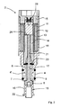
- inventive valve 1 shows a 2/2-way valve for a gaseous working fluid, here compressed air, and includes an electromagnetic actuator 2 and a valve housing 3, in which this actuator 2 is used.
- This valve housing 3 has at least one inlet channel 4 and at least one outlet channel 5.
- These channels 4, 5 communicate with each other in the open position of the valve 1 via an intermediate flow channel.
- this flow-through channel can be pressure-tightly interrupted in the closed position of the valve 1, namely in an inlet-channel-side valve chamber 6 and an outlet-chamber-side outlet chamber 6 '.
- the electromagnetic actuator 2 comprises an armature 11, a winding 12, a bobbin 13, a pole 14, a yoke 15 and an actuator housing 16.
- This actuator housing 16 is fixedly connected to the valve housing 3 and has in its interior a valve stem 17, which from the anchor 11 in axial direction is movable and at the opposite end has an elastic molding 18.
- This elastic molded part 18 acts as a resilient return element 10 for the valve stem 17 and lies sealingly on a bottom 19 of the outlet chamber 6 '. Structure and operation of the electromagnetic actuator 2 to be in Fig. 2 be explained in more detail.
- the in Fig. 2 shown electromagnetic actuator 2 has an armature 11, a winding 12, a bobbin 13, a pole 14, a yoke 15 and an actuator housing 16.
- the valve stem 17 comprises on the drive side an axially movable valve pin 21 in the yoke 14 and outlet valve side 8.
- the plunger 17 is fixedly connected to an elastic molding 18, this elastic molding 18 fully embeds the valve stem 8 and a base portion 22 on the floor 19 of the outlet chamber 6 'rests tightly.
- a non-abrasive sealing element 23 in the form of a membrane seal between plunger 17 and pole 14 closes the valve chamber 6 on the drive side pressure-tight.
- valve chamber 6 is filled via the inlet channel 4 and any further channels 4 'with a pressurized gaseous working medium.
- the plunger 17 is pressed against the armature 11 of the actuator 2 via the non-abrasive elastic sealing element 23 (in this case a diaphragm seal).
- the armature 11 is supported with a spring element 28 on the yoke 15 and is therefore permanently on the valve pin 21 of the valve stem 17.
- the incorporated in the actuator housing 16 valve seat 7 rests with its contact surface sealingly against the coated contact surface of the valve stem head 8.
- the pressure-loaded surface parts of the membrane seal 23 and the coated plunger head 8 are dimensioned such that the forces acting on these surface parts mutually compensate each other.
- the armature 11 is pulled against the pole 14.
- the valve stem 17 is pushed in the direction of the outlet channel 5 and creates a passage opening between the contact surfaces of the valve seat 7 and the tappet head 8.
- This opening movement of the plunger 17 simultaneously leads to a compression and / or bulging of the elastic molded part 18.
- the excitation current of the electromagnetic drive 2 is turned off and presses that elastic molded part 18 the valve stem 8 of the valve stem 17 against the valve seat 7.
- the armature 11 is separated by a predetermined stroke 24 from the pole 14 again.
- the elastic molded part 18 is made of the same material and is molded in a suitable injection mold to the plunger head 8.
- the special geometry of the valve stem 17 and of the elastic molded part 18 make it possible to use an injection-molding tool which can be separated, for example, in the area of the base part 22 of the elastic molded part 18 and thus produces a radially circumferential separating ridge.
- This in Fig. 3 illustrated inventive valve has an electromagnetic actuator 2, which is constructed in substantially the same manner as in Fig. 2 described and includes an armature 11, a winding 12, a bobbin 13, a pole 14, a yoke 15 and an actuator housing 16.
- the valve stem 17 has a drive side in the yoke 14 axially movable valve pin 21 and includes the outlet channel side a valve stem 8.
- This valve stem 17 is fixedly connected to an elastic molded part 18, wherein this elastic molded part 18 fully embeds the plunger head 8 and rests tightly with a base part 22 on the bottom 19 of the outlet chamber 6 '.
- this elastic molded part 18 fully embeds the plunger head 8 and rests tightly with a base part 22 on the bottom 19 of the outlet chamber 6 '.
- valve chamber 6 is here no sealing element inserted in the form of a membrane seal between the plunger 17 and pole 14, but the pressure communicating with the valve chamber 6 and in operation pressurized interior of the actuator 2 on the yoke side pressure-tight, in particular by means of a between the yoke 15 and the housing 16th the actuator arranged annular seal 25.
- This embodiment for the actuator 2 differs from that according to Fig. 2 in addition by a through the valve stem head 8 and the molding 18 in a pressure compensation chamber 27 leading pressure equalization hole 26.
- the valve chamber 6 via the inlet channel 4 and any other inlet channels with a pressurized gaseous working fluid (compressed air) is filled.
- This actuator side can not escape from the interior of the actuator housing 16 because of the ring seal 25 and can not expose the valve seat 7, which abuts with its contact surface sealingly against the contact surface of the coated plunger head 8, since the pressure compensation chamber 27 located in the interior of the elastic molded part 18 is dimensioned such that, with the exception of a small portion, the forces generated in the closed state by the working medium and acting on the pressure-loaded surface parts mutually compensate each other.
- the pressure compensation chamber 27 located in the interior of the elastic molded part 18 is dimensioned such that, with the exception of a small portion, the forces generated in the closed state by the working medium and acting on the pressure-loaded surface parts mutually compensate each other.
- the armature 11 is supported with a spring element 28 on the yoke 15 and is therefore permanently on the valve pin 21 of the valve stem 17.
- the valve stem 17 is pushed in the direction of the outlet channel and creates a passage opening between the contact surfaces of the valve seat 7 and the plunger head 8.
- This opening movement of the plunger 17 simultaneously leads to compression and / or bulging of the elastic molded part 18.
- To the passage opening of the valve again To close the excitation current of the electromagnetic drive is turned off.
- the elastic molded part 18 then presses the plunger head 8 of the valve stem 17 against the valve seat 7.
- the armature 11 is separated by a predetermined stroke 24 from the pole 14.
- a valve capsule 3 ' which encapsulates the actuator 2 completely.
- the electromagnetic actuator 2 is constructed substantially in the same manner as in FIG Fig. 3 described, however, in this embodiment no special sealing element in the form of a ring seal for the actuator 2 is required. In contrast to the embodiment according to Fig. 2 here is also no sealing element in the form of a membrane seal required.
- the valve capsule 3 ' has a capsule wall 3'", which is firmly connected to the valve housing 3, preferably integrally formed and with a capsule lid 3" is tightly closed.
- connection point between the capsule wall 3 '"and the capsule lid 3" is pressure-tight sealable, in particular by means of a sealing element 20.
- a sealing element 20 eg pressure-tight snap, screw and / or conical surfaces
- an additional sealing element of conventional type greyase
- Essential in this embodiment is the flameproof enclosure of the actuator 2 used in the valve housing 3 in order to avoid pressure losses in the valve chamber 6.
- valve arrangement according to the invention are directly apparent to the person skilled in the art and can be seen in particular in avoiding the mechanical and intrinsic friction losses (sliding sealing elements, deformation forces for upsetting, stretching or bending of the membrane seals) and in the reduction of the abrasion and the electrical power loss generated thereby. respectively.
- Operating power for the actuator and in particular to enable faster switching times.
- the reduction of the operating power for the actuator also allows a reduction in the dimensioning of the individual components of the actuator and thus a more compact arrangement within a valve group for example.
- a blow-out or sorting device The reduction of the stroke movement leads to faster switching times with the same power of the actuator.
- the particular configuration and arrangement of the inventive molding allows an injection molding tool to be axially separated during injection molding onto the valve head and thus does not produce a longitudinally directed separating ridge running over the valve head, but rather a radially circumferential separating ridge, preferably in the region of the base part of the molding. This also no reworking is required, ie the elastomer skin remains intact, ie the surface is not subsequently roughened by post-treatment. damaged. By balancing the pressure ratios within the valve, the required power of the solenoid coils can be substantially reduced. Assembly and disassembly of the valve and its actuator are simplified by the proposed sizing (design).
- valve according to the invention is thus to be seen in the simple assembly, the wear-free and low-maintenance mode of operation and the longevity.
- this frictionless valve assembly is particularly suitable for use with dry gases, as no Lubricants (impurities) are required. It is understood that no forces are required by the loose guidance of the valve stem to overcome static friction and sliding.
- valve according to the invention can be used not only in the sorting plants mentioned above for recycling plants, but also in sorting and distribution plants of all kinds, in particular in mail sorting plants, piece goods packaging plants, dosing Installations in the food and pharmaceutical industry or in blow-off or blow-off stations in manufacturing plants, among others.
Landscapes
- Engineering & Computer Science (AREA)
- General Engineering & Computer Science (AREA)
- Mechanical Engineering (AREA)
- Magnetically Actuated Valves (AREA)
- Valve Device For Special Equipments (AREA)
Abstract
Description
- Die vorliegende Erfindung betrifft ein druckbalanciertes Ventil mit Stellantrieb, vorzugsweise ein 2/2-Weg-Ventil für ein gasförmiges Arbeitsmedium, gemäss Oberbegriff des Anspruchs 1.
- Solche Ventile finden ihre Verwendung generell als einfache Absperr-, resp. Durchgangsventile, um das Durchströmen eines bspw. gasförmigen Mediums zwischen einem Einström- und einem Ausströmkanal zu steuern. Mit dem vorliegenden Ventil soll insbesondere eine Sortiervorrichtung, wie bspw. bei einer Recycling-Anlage, bestückt werden können, um zerkleinerte Einzelteile mit vorgespannten gasförmigen Medien, insbesondere Druckluft, voneinander zu separieren. Solche Recycling-Anlagen sind hinlänglich bekannt und werden bspw. in der
WO2007068697 oderEP-1752228 näher beschrieben. - Die mit diesen Recycling-Anlagen verwendeten Sortiervorrichtungen umfassen ganze Batterien von einzeln aktivierbaren Druckluftdüsen, wie sie bspw. aus der
EP-1754550 (Fig.3 ) bekannt sind. Insbesondere offenbart diese Druckschrift ein druckbalanciertes 2/2-Weg-Ventil mit einem unabhängigen Stellantrieb, insbesondere mit einem elektromagnetischen Aktuator. Ein für denselben Verwendungszweck vorgesehenes druckbalanciertes 2/2-Weg-Ventil wird in derUS-2008/0251748 (Fig.9) offenbart. Ventile mit dieser Bauart sollen im Folgenden auch als schleifende Ventile bezeichnet werden und umfassen ein Ventilgehäuse mit einer Ventilkammer und mindestens einem damit kommunizierenden Einlass- und Auslasskanal, wobei in der Ventilkammer zwischen dem Einlasskanal und dem Auslasskanal mindestens ein Ventilsitz vorgesehen ist und ein Ventilstössel (Poppet) bewegbar angeordnet ist. Diese Ventile umfassen darüber hinaus einen elektromagnetischen Stellantrieb, um den Ventilstössel in eine Durchströmstellung zu verschieben, sowie eine federelastische Rückstellfeder, um den Ventilstössel in eine Schliessstellung zu bringen. Um die Dichtheit zu gewährleisten ist der Ventilstössel mit O-Ringen oder ähnlichen Elementen versehen, welche den Raum zwischen Ventilstössel und Ventilkammer abdichten. - Leider verschleissen diese Dichtungen, resp. O-Ringe wegen der häufigen und schleifenden Bewegungen innerhalb der Ventilkammer sehr rasch und es lagert sich deshalb auch viel unerwünschter Abrieb ab. Diese Ablagerungen führen zu Beeinträchtigungen der Funktionsfähigkeit, resp. Schaltleistung. Insbesondere führen diese Ablagerungen zur Verlangsamung der Schliess- und Öffnungsbewegung und damit zu einer unerwünschten Verlängerung der Zykluszeiten. Insbesondere auch deshalb, weil beim Übergang von Haftreibung zu Gleitreibung erhöhte Kräfte beim Stellantrieb, z.B. ein Elektromagnet, erforderlich werden, welche bei einem optimiert ausgelegten Stellantrieb jedoch nicht zur Verfügung stehen. Die Reibungsverluste bei diesen Ventilen erfordern starke Stellantriebe und stehen einer Miniaturisierung im Weg. Ausserdem wird durch diese Ablagerungen nicht nur die Schliesskraft des Ventils verringert sondern wird auch die Innenfläche der Ventilkammer beschädigt, was wiederum zu irreversiblen Leckagen führen kann. Eine regelmässige und häufige Wartung dieser Ventile ist unumgänglich.
- Es ist deshalb auch schon vorgeschlagen worden die schleifenden Dichtungen (O-Ringe) durch eine elastische Membrane (Diaphragma) zu ersetzen. Ein derartiges Ventil wird bspw. in der
US2012/0061600 (Fig.3 ) beschrieben und soll im Folgenden als nicht-schleifendes oder membranbasiertes Ventil bezeichnet werden. Ventile dieser Bauart weisen anstelle der schleifenden Dichtungselemente (meist O-Ringe) und zur Bildung einer Durchströmkammer ein erstes und ein zweites, diese Durchströmkammer begrenzendes, nicht-schleifendes Dichtungselement in Form einer elastischen Membran auf. Der innerhalb dieser Durchströmkammer liegende Teil des Ventilstössels weist einen Ventilkopf auf, welcher in Schliessstellung am Ventilsitz anliegt und in Durchströmstellung den Ventilsitz frei gibt. Es versteht sich, dass die in Schliessstellung aufeinanderliegenden Stossflächen von Ventilkopf und Ventilsitz so dimensioniert und gestaltet (designed) sein müssen, dass diese das Ventil in Schliessstellung druckdicht verschliessen. Vorzugsweise ist bei den Ventilen dieser Art der Ventilkopf mit einem Elastomer überzogen, um die gewünschte Dichtheit zu gewährleisten. Dieses Elastomer wird in der Regel vorgängig mit Hilfe eines Spritzgiesswerkzeugs auf den Ventilkopf aufgebracht. - Leider erweist sich die Montage solcher membranbasierter Ventile als äusserst aufwändig und es können diese nicht in einfacher Weise ersetzt oder unterhalten werden. Insbesondere erfordert die Revision eines fehlerhaft funktionierenden Ventils eine aufwändige Zerlegung vor Ort, was die Standzeit der betroffenen Anlage bspw. eine Sortiervorrichtung, in unerwünschter Weise verlängert. Darüber hinaus entsteht beim Anspritzen des Elastomers immer auch ein Trenngrat (mould parting line), welche das abdichtende Anliegen von Ventilkopf und Ventilsitz in der Schliessstellung behindert, d.h. die Dichtheit des Ventils in Schliessstellung beeinträchtigt. Dieser Trenngrat wird deshalb meist nachträglich abgeschliffen, was einen weiteren unerwünschten (kostengenerierenden) Herstellungsschritt erfordert und in der Verwendung auch zu einer Schwachstelle führt, insbesondere weil die angeschliffenen Stellen aufgeraut sind, d.h. keine glatte Haut mehr aufweisen und deshalb Feuchtigkeit, Schmutz, etc. rasch aufnehmen.
- Es ist deshalb Aufgabe der vorliegenden Erfindung ein druckbalanciertes Ventil, vorzugsweise ein 2/2-Weg-Ventil für ein gasförmiges Arbeitsmedium zu schaffen, welches die Nachteile der schleifenden und/oder nicht-schleifenden Ventile bekannter Art nicht aufweist. Insbesondere sollen mit der vorliegenden Erfindung die mechanischen Reibungsverluste minimiert werden, um damit die Betriebsleistung für den Stellantrieb reduzieren zu können und schnellere Schaltzeiten zu ermöglichen. Mit der Reduktion der mechanischen Reibungsverluste soll auch die Lebensdauer dieser Ventile substanziell erhöht werden. Es ist eine weitere Aufgabe der vorliegenden Erfindung eine kompaktere und einfacher montier- resp. demontierbare Bauweise des Ventils zu schaffen.
- Diese Aufgabe wird erfindungsgemäss mit einem Ventil mit den Merkmalen des Anspruchs 1 gelöst. Insbesondere ist dieses für ein vorgespanntes, gasförmiges Arbeitsmedium (z.B. Druckluft) geeignet und vorzugsweise als ein druckbalanciertes 2/2-Weg-Ventil ausgebildet. Dieses Ventil umfasst ein Ventilgehäuse mit einer Ventilkammer, mindestens einen Einlasskanal und mindestens einen Auslasskanal, sowie einen elektromagnetischen Stellantrieb mit einem Anker, einer Wicklung, einem Spulenkörper, einem Pol, einem Joch und einem Stellantriebsgehäuse, sowie einen in diesen Stellantrieb ragenden Ventilstössel, welcher einen antriebsseitigen Ventilstösselstift und einen auslasskanalseitigen Ventilstösselkopf aufweist, sowie ein mit diesem Ventilstössel zusammenwirkendes federelastisches Rückstellelement. Zwischen dem Einlasskanal und dem Auslasskanal ist mindestens ein Ventilsitz vorgesehen. Der Ventilstösselkopf ist mit einer Ventilstösselkopfbeschichtung versehen. Das Ventil weist zur Abdichtung der Ventilkammer mindestens ein nicht-schleifendes Dichtungselement auf, wobei das federelastische Rückstellelement und die Ventilkopfbeschichtung miteinander stoffschlüssig verbunden sind, d.h. ein elastisches Formteil bilden.
- In einer bevorzugten Ausführungsform ist das elastische Formteil aus demselben Material, insbesondere einem Elastomer, gebildet, d.h. ist ein einstückiges Formteil und insbesondere ein spritzgegossenes Formteil. Vorteilhafterweise weist dieses Formteil keinen längs verlaufenden, sondern einen radial umlaufenden Trenngrat auf.
- Erfindungsgemäss ist das Formteil derart dimensioniert, dass das Ventil druckbalanciert ist, d.h. dass das Formteil derart gestaltet und dimensioniert ist, dass sich im geschlossenen Zustand die vom Arbeitsmedium erzeugten und auf die druckbelasteten Flächenteile der beweglichen Ventilteile wirkenden Kräfte gegenseitig kompensieren.
- In einer ersten bevorzugten Ausführungsform ist das nicht-schleifende Dichtungselement als Membrandichtung ausgebildet, welche die unter Druck stehende Ventilkammer antriebsseitig druckdicht abschliesst und vorzugsweise zwischen dem Pol und dem Gehäuse des Stellantriebs angeordnet ist.
- In einer zweiten besonderen Ausführungsform ist das nicht-schleifende Dichtungselement als Ringdichtung ausgebildet, welche den mit der Ventilkammer kommunizierenden und in Betrieb unter Druck stehenden Innenraum des Stellantriebs antriebsseitig druckdicht abschliesst und vorzugsweise zwischen dem Joch und dem Gehäuse des Stellantriebs angeordnet ist.
- In einer weiteren dritten Ausführungsform ist das nicht-schleifende Dichtungselement eine Dichtung geeigneter Art, welche den mit der Ventilkammer kommunizierenden und in Betrieb unter Druck stehenden Innenraum einer Ventilgehäusekapsel eingekapselten Stellantrieb druckdicht abschliesst und vorzugsweise zwischen einem Kapseldeckel und einer Kapselwand angeordnet ist.
- Weitere bevorzugte Ausführungsformen weisen die Merkmale der Unteransprüche auf.
- Im Folgenden soll die vorliegende Erfindung anhand einiger Ausführungsbeispiele und mit Hilfe der Figuren näher erläutert werden. Dabei zeigt:
- Fig. 1:
- einen schematischen Querschnitt durch eine erste Ausführungsform eines erfindungsgemässen Ventils und dessen Stellantrieb;
- Fig. 2:
- einen schematischen Querschnitt durch den Stellantrieb
Fig. 1 ; - Fig. 3:
- einen schematischen Querschnitt durch eine zweite Ausführungsform eines erfindungsgemässen Ventils und dessen Stellantrieb;
- Fig. 4:
- einen schematischen Querschnitt durch eine dritte Ausführungsform eines erfindungsgemässen Ventils und dessen Stellantrieb.
- Das in
Fig. 1 dargestellte, erfindungsgemässe Ventil 1 zeigt ein 2/2-Weg-Ventil für ein gasförmiges Arbeitsmedium, hier Druckluft, und umfasst einen elektromagnetischen Stellantrieb 2 sowie ein Ventilgehäuse 3, in welches dieser Stellantrieb 2 eingesetzt ist. Dieses Ventilgehäuse 3 weist mindestens einen Einlasskanal 4 und mindestens einen Auslasskanal 5 auf. Diese Kanäle 4, 5 kommunizieren in Öffnungsstellung des Ventils 1 über einen dazwischenliegenden Durchströmkanal miteinander. Mit Hilfe der Kontaktflächen eines Ventilsitzes 7 und eines Stösselkopfs 8 lässt sich dieser Durchströmkanal in Schliessstellung des Ventils 1 druckdicht unterbrechen, nämlich in eine einlasskanalseitige Ventilkammer 6 und eine auslasskanalseitige Auslasskammer 6'. Der elektromagnetische Stellantrieb 2 umfasst einen Anker 11, eine Wicklung 12, einen Spulenkörper 13, einen Pol 14, ein Joch 15 und ein Stellantriebsgehäuse 16. Dieses Stellantriebsgehäuse 16 ist mit dem Ventilgehäuse 3 fest verbunden und weist in seinem Innern einen Ventilstössel 17 auf, welcher vom Anker 11 in axialer Richtung bewegbar ist und am entgegengesetzten Ende ein elastisches Formteil 18 aufweist. Dieses elastische Formteil 18 wirkt als federelastisches Rückstellelement 10 für den Ventilstössel 17 und liegt auf einem Boden 19 der Auslasskammer 6' abdichtend auf. Aufbau und Wirkungsweise des elektromagnetischen Stellantriebs 2 sollen inFig. 2 näher erläutert werden. - Der in
Fig. 2 dargestellte elektromagnetische Stellantrieb 2 weist einen Anker 11, eine Wicklung 12, einen Spulenkörper 13, einen Pol 14, ein Joch 15 und ein Stellantriebsgehäuse 16 auf. Der Ventilstössel 17 umfasst antriebsseitig einen im Joch 14 axial beweglichen Ventilstift 21 und auslasskanalseitig einen Ventilstösselkopf 8. Erfindungsgemäss ist der Stössel 17 mit einem elastischen Formteil 18 fest verbunden, wobei dieses elastische Formteil 18 den Ventilstösselkopf 8 vollständig einbettet und mit einer Sockelpartie 22 auf dem Boden 19 der Auslasskammer 6' dicht aufliegt. Ein nicht-schleifendes Dichtungselement 23 in Form einer Membrandichtung zwischen Stössel 17 und Pol 14 schliesst die Ventilkammer 6 antriebsseitig druckdicht ab. Im Betrieb wird die Ventilkammer 6 über den Einlasskanal 4 und allfällige weitere Kanäle 4' mit einem unter Druck stehenden gasförmigen Arbeitsmedium gefüllt. Dadurch wird der Stössel 17 über das nicht-schleifende elastische Dichtungselement 23 (hier eine Membrandichtung) gegen den Anker 11 des Stellantriebs 2 gedrückt. Der Anker 11 ist mit einem Federelement 28 am Joch 15 abgestützt und liegt deshalb permanent am Ventilstift 21 des Ventilstössels 17 auf. Der in das Stellantriebsgehäuse 16 eingearbeitete Ventilsitz 7 liegt dabei mit seiner Kontaktfläche abdichtend an der beschichteten Kontaktfläche des Ventilstösselkopfes 8 an. Zur Erzeugung eines druckbalancierten Ventils sind die druckbelasteten Flächenteile der Membrandichtung 23 und des beschichteten Stösselkopfes 8 derart dimensioniert, dass sich die auf diese Flächenteile wirkenden Kräfte gegenseitig kompensieren. Bei Aktivierung des Elektromagnets, resp. dessen Wicklung 12, wird der Anker 11 gegen den Pol 14 gezogen. Dabei wird der Ventilstössel 17 in Richtung des Auslasskanals 5 gestossen und entsteht eine Durchlassöffnung zwischen den Kontaktflächen des Ventilsitzes 7 und des Ventilstösselkopfes 8. Diese Öffnungsbewegung des Stössels 17 führt gleichzeitig zu einer Kompression und/oder Ausbauchung des elastischen Formteils 18. Um die Durchlassöffnung des Ventils wieder zu schliessen wird der Erregerstrom des elektromagnetischen Antriebs 2 ausgeschaltet und drückt das elastische Formteil 18 den Ventilstösselkopf 8 des Ventilstössels 17 gegen den Ventilsitz 7. Damit wird auch der Anker 11 um einen vorgegebenen Hub 24 vom Pol 14 wieder getrennt. - Vorzugsweise ist das elastische Formteil 18 aus demselben Material gefertigt und wird in einem geeigneten Spritzgiesswerkzeug an den Stösselkopf 8 angespritzt. Die besondere Geometrie des Ventilstössels 17 und des elastischen Formteils 18 erlauben es ein Spritzgiesswerkzeug zu verwenden, welches sich bspw. im Bereich der Sockelpartie 22 des elastischen Formteils 18 trennen lässt und damit einen radial umlaufenden Trenngrat erzeugt.
- Das in
Fig. 3 dargestellte erfindungsgemässe Ventil weist einen elektromagnetischen Stellantrieb 2 auf, welcher im Wesentlichen in derselben Weise aufgebaut ist, wie inFig. 2 beschrieben und umfasst einen Anker 11, eine Wicklung 12, einen Spulenkörper 13, einen Pol 14, ein Joch 15 und ein Stellantriebsgehäuse 16. Der Ventilstössel 17 weist einen antriebsseitig im Joch 14 axial beweglichen Ventilstift 21 auf und umfasst auslasskanalseitig einen Ventilstösselkopf 8. Dieser Ventilstössel 17 ist mit einem elastischen Formteil 18 fest verbunden, wobei dieses elastische Formteil 18 den Stösselkopf 8 vollständig einbettet und mit einer Sockelpartie 22 auf dem Boden 19 der Auslasskammer 6' dicht aufliegt. Im Unterschied zur Ausführungsform gemässFig. 2 ist hier kein Dichtungselement in Form einer Membrandichtung zwischen Stössel 17 und Pol 14 eingefügt, sondern ist der mit der Ventilkammer 6 kommunizierende und im Betrieb unter Druck stehende Innenraum des Stellantriebs 2 jochseitig druckdicht abgedichtet, insbesondere mit Hilfe einer zwischen dem Joch 15 und dem Gehäuse 16 des Stellantriebs angeordneten Ringdichtung 25. Diese Ausführungsform für den Stellantrieb 2 unterscheidet sich von derjenigen gemässFig. 2 ausserdem durch eine durch den Ventilstösselkopf 8 und das Formteil 18 in eine Druckausgleichskammer 27 führende Druckausgleichsbohrung 26. Im Betrieb wird die Ventilkammer 6 über den Einlasskanal 4 und allfällige weitere Einlasskanäle mit einem unter Druck stehenden gasförmigen Arbeitsmedium (Druckluft) gefüllt. Dieses kann wegen der Ringdichtung 25 stellantriebsseitig nicht aus dem Innenraum des Stellantriebsgehäuse 16 entweichen und kann den Ventilsitz 7, welcher mit seiner Kontaktfläche abdichtend an der Kontaktfläche des beschichteten Stösselkopfes 8 anliegt, nicht freilegen, da die im Innern des elastischen Formteils 18 liegende Druckausgleichskammer 27 derart dimensioniert ist, dass sich bis auf einen geringen Anteil, die im geschlossenen Zustand vom Arbeitsmedium erzeugten und auf die druckbelasteten Flächenteile wirkenden Kräfte gegenseitig kompensieren. Zur Erzeugung eines druckbalancierten Ventils sind also lediglich die beidseitig des Ventilsitzes 7 liegenden und druckbelasteten Flächenteile zu berücksichtigen. Beim Aktivieren des Elektromagnets, resp. dessen Wicklung 12, wird der Anker 11 gegen den Pol 14 gezogen. Der Anker 11 ist mit einem Federelement 28 am Joch 15 abgestützt und liegt deshalb permanent am Ventilstift 21 des Ventilstössels 17 auf. Dabei wird der Ventilstössel 17 in Richtung des Auslasskanals gestossen und entsteht eine Durchlassöffnung zwischen den Kontaktflächen des Ventilsitzes 7 und des Stösselkopfes 8. Diese Öffnungsbewegung des Stössels 17 führt gleichzeitig zu einer Kompression und/oder Ausbauchung des elastischen Formteils 18. Um die Durchlassöffnung des Ventils wieder zu schliessen wird der Erregerstrom des elektromagnetischen Antriebs ausgeschaltet. Das elastische Formteil 18 drückt dann den Stösselkopf 8 des Ventilstössels 17 gegen den Ventilsitz 7. Damit wird auch der Anker 11 um einen vorgegebenen Hub 24 vom Pol 14 getrennt. Dieser Aufbau ermöglicht es die axiale Bewegung des Ventilstössels 17 und damit des Ventilstifts 21 präzis zu bestimmen und zu minimieren. Insbesondere lässt sich durch diese Minimierung die Schaltzeit des Ventils wesentlich reduzieren. - Die in
Fig. 4 dargestellte Ausführungsform des erfindungsgemässen Ventils 1 unterscheidet sich von den vorgehend beschriebenen Ausführungsformen im Wesentlichen durch eine Ventilkapsel 3', welche den Stellantrieb 2 vollständig einkapselt. Der elektromagnetische Stellantrieb 2 ist im Wesentlichen in derselben Weise aufgebaut, wie inFig. 3 beschrieben, jedoch ist bei dieser Ausführungsform kein besonderes Dichtungselement in Form einer Ringdichtung für den Stellantrieb 2 erforderlich. Im Unterschied zur Ausführungsform gemässFig. 2 ist hier auch kein Dichtungselement in Form einer Membrandichtung erforderlich. Die Ventilkapsel 3' weist eine Kapselwand 3'" auf, welche mit dem Ventilgehäuse 3 fest verbunden, vorzugsweise einstückig ausgebildet ist und mit einem Kapseldeckel 3" dicht verschliessbar ist. Erfindungsgemäss ist die Verbindungsstelle zwischen der Kapselwand 3'" und dem Kapseldeckel 3" druckdicht verschliessbar, insbesondere mit Hilfe eines Dichtungselementes 20. Dafür kann eine besondere Formgebung (z.B. druckdichte Schnapp-, Schraub- und/oder Konusflächen) vorgesehen sein und/oder ist ein zusätzliches Dichtungselement konventioneller Art (Fett) verwendbar und/oder kann dieses in Form einer zusätzlichen Ringdichtung eingesetzt sein. Wesentlich bei dieser Ausführungsform ist die druckfeste Kapselung des im Ventilgehäuse 3 eingesetzten Stellantriebs 2, um Druckverluste in der Ventilkammer 6 zu vermeiden. - Die Vorteile der erfindungsgemässen Ventilanordnung sind dem Fachmann unmittelbar ersichtlich und insbesondere in der Vermeidung der mechanischen und intrinsischen Reibungsverluste (schleifende Dichtungselemente, Deformationskräfte für das Stauchen, Dehnen oder Biegen der Membrandichtungen) zu sehen sowie in der dadurch erzeugten Reduktion des Abriebs und der elektrischen Verlustleistung, resp. Betriebsleistung für den Stellantrieb sowie insbesondere in der Ermöglichung schnellerer Schaltzeiten. Die Reduktion der Betriebsleistung für den Stellantrieb erlaubt ausserdem eine Reduktion der Dimensionierung der einzelnen Bauteile des Stellantriebs und damit eine kompaktere Anordnung innerhalb einer Ventilgruppe für bspw. eine Ausblas- oder Sortiervorrichtung. Die Reduktion der Hubbewegung führt zu rascheren Schaltzeiten bei gleicher Leistung des Stellantriebs.
Die besondere Ausgestaltung und Anordnung des erfindungsgemässen Formteils erlaubt beim Anspritzen an den Ventilkopf ein axiales Trennen des Spritzgiesswerkzeugs und erzeugt damit keinen längs gerichteten, über den Ventilkopf laufenden Trenngrat, sondern einen radial umlaufenden Trenngrat, vorzugsweise im Bereich der Sockelpartie des Formteils. Damit ist auch keine Nachbearbeitung mehr erforderlich, d.h. bleibt die Elastomer-Haut intakt, d.h. wird die Oberfläche durch Nachbehandlung nicht nachträglich noch aufgeraut resp. beschädigt. Durch das Ausbalancieren der Druckverhältnisse innerhalb des Ventils kann die erforderliche Leistung der Magnetspulen substantiell reduziert werden. Montage und Demontage des Ventils und seines Stellantriebs werden durch die vorgeschlagene Dimensionierung (Design) vereinfacht. Ein besonderer Vorteil des erfindungsgemässen Ventils ist also in der einfachen Montage, der verschleissfreien und unterhaltsarmen Betriebsweise sowie der Langlebigkeit zu sehen. Darüber hinaus eignet sich diese reibungsfreie Ventilanordnung besonders für den Einsatz mit trockenen Gasen, da keine Schmiermittel (Verunreinigungen) erforderlich sind. Es versteht sich, dass durch die lose Führung des Ventilstössels keine Kräfte erforderlich sind um Haft- und Gleitreibung überwinden zu müssen. - Es versteht sich ausserdem, dass das erfindungsgemässe Ventil nicht nur bei den eingangs genannten Sortieranlagen für Recycling-Anlagen eingesetzt werden kann, sondern auch in Sortier- und Verteiler-Anlagen aller Art, insbesondere in Postsortier-Anlagen, Stückgut-Verpackungs-Anlagen, Dosier-Anlagen in der Nahrungsmittel- und Pharmaindustrie oder in Ausblas- oder Abblasstationen bei Fertigungsanlagen, u.a..
-
- 1.
- druckbalanciertes Ventil
- 2.
- Stellantrieb
- 3.
- Ventilgehäuse
- 3'.
- Ventilkapsel
- 3".
- Kapseldeckel
- 3"'.
- Kapselwand
- 4.
- Einlasskanal
- 5.
- Auslasskanal
- 6.
- Ventilkammer
- 6'.
- Auslasskammer
- 7.
- Ventilsitz
- 8.
- Ventilstösselkopf
- 9.
- Ventilstösselkopfbeschichtung
- 10.
- Federelastisches Rückstellelement
- 11.
- Anker
- 12.
- Wicklung
- 13.
- Spulenkörper
- 14.
- Pol
- 15.
- Joch
- 16.
- Stellantriebsgehäuse
- 17.
- Ventilstössel
- 18.
- elastisches Formteil
- 19.
- Boden
- 20.
- nicht-schleifendes Dichtungselement
- 21.
- Ventilstift
- 22.
- Sockelpartie
- 23.
- Dichtungselement in Form einer Membrandichtung
- 24.
- Hub
- 25.
- Dichtungselement in Form einer Ringdichtung
- 26.
- Druckausgleichsbohrung
- 27.
- Druckausgleichskammer
- 28.
- Federelement
Claims (10)
- Druckbalanciertes Ventil (1), vorzugsweise ein 2/2-Weg-Ventil für ein gasförmiges Arbeitsmedium (Druckluft), umfassend ein Ventilgehäuse (3) mit einer Ventilkammer (6) und mit mindestens einem mit dieser Ventilkammer (6) kommunizierenden Einlasskanal (4) und mit mindestens einem Auslasskanal (5), sowie einen elektromagnetischen Stellantrieb (2) mit einem Anker (11), einer Wicklung (12), einem Spulenkörper (13), einem Pol (14), einem Joch (15) und einem Stellantriebsgehäuse (16), sowie einen in dieses Stellantriebsgehäuse (16) ragenden Ventilstössel (17), welcher einen antriebsseitigen Ventilstift (21) und einen auslasskanalseitigen Ventilstösselkopf (8) aufweist, sowie ein mit diesem Ventilstössel (17) zusammenwirkendes federelastisches Rückstellelement (10),
wobei zwischen dem Einlasskanal (4) und dem Auslasskanal (5) mindestens ein Ventilsitz (7) vorgesehen ist, wobei der Ventilstösselkopf (8) mit einer Ventilstösselkopfbeschichtung (9) versehen ist, wobei das Ventil (1) zur Abdichtung der unter Druck stehenden Ventilkammer (6) mindestens ein nicht-schleifendes Dichtungselement (20, 23, 25) aufweist,
dadurch gekennzeichnet, dass
das federelastische Rückstellelement (10) und die Ventilstösselkopfbeschichtung (9) miteinander stoffschlüssig verbunden sind, d.h. ein elastisches Formteil (18) bilden. - Ventil (1) nach Anspruch 1, dadurch gekennzeichnet, dass das elastische Formteil (18) aus demselben Material, insbesondere einem Elastomer, gebildet ist, d.h. ein einstückiges Formteil ist.
- Ventil (1) nach Anspruch 2, dadurch gekennzeichnet, dass das elastische Formteil (18) ein spritzgegossenes Formteil ist.
- Ventil (1) nach Anspruch 3, dadurch gekennzeichnet, dass das elastische Formteil (18) einen radial umlaufenden Trenngrat aufweist.
- Ventil (1) nach Anspruch 1, dadurch gekennzeichnet, dass das nicht-schleifende Dichtungselement (20, 23, 25) eine Membrandichtung ist, welche die Ventilkammer (6) antriebsseitig druckdicht abschliesst und vorzugsweise zwischen dem Pol (14) und dem Gehäuse (16) des Stellantriebs angeordnet ist.
- Ventil nach Anspruch 1, dadurch gekennzeichnet, dass das nicht-schleifende Dichtungselement (20, 23, 25) eine Ringdichtung ist, welche den mit der Ventilkammer (6) kommunizierenden und in Betrieb unter Druck stehenden Innenraum des Stellantriebs (2) antriebsseitig druckdicht abschliesst und vorzugsweise zwischen dem Joch (15) und dem Gehäuse (16) des Stellantriebs (2) angeordnet ist.
- Ventil (1) nach Anspruch 1, dadurch gekennzeichnet, dass das nicht-schleifende Dichtungselement (20, 23, 25) eine Dichtung ist, welche den über den eingekapselten Stellantrieb (2) mit der Ventilkammer (6) kommunizierenden und in Betrieb unter Druck stehenden Innenraum einer Ventilgehäusekapsel (3') druckdicht abschliesst und vorzugsweise zwischen einem Kapseldeckel (3") und einer Kapselwand (3"') angeordnet ist.
- Ventil (1) nach einem der Ansprüche 5 bis 7, dadurch gekennzeichnet, dass das Ventil (1) derart dimensioniert ist, dass sich im geschlossenen Zustand die vom Arbeitsmedium erzeugten und auf die druckbelasteten Flächenanteile der beweglichen Teile wirkenden Kräfte gegenseitig kompensieren.
- Ventil (1) nach einem der vorherigen Ansprüche 1 bis 8, dadurch gekennzeichnet, dass zwischen dem Joch (15) und dem Anker (11) ein Federelement (28) angeordnet ist.
- Elektromagnetischer Stellantrieb (2) für ein druckbalanciertes Ventil (1) gemäss Anspruch 1, welcher Stellantrieb (2) einen Anker (11), eine Wicklung (12), einen Spulenkörper (13), einen Pol (14), ein Joch (15) und ein Stellantriebsgehäuse (16) umfasst, sowie einen in dieses Stellantriebsgehäuse (16) ragenden Ventilstössel (17) umfasst, welcher Ventilstössel (17) einen antriebsseitigen Ventilstift (21) und einen auslasskanalseitigen Ventilstösselkopf (8) aufweist, welcher Stellantrieb (2) ein mit diesem Ventilstössel (17) zusammenwirkendes federelastisches Rückstellelement (10) umfasst, wobei der Ventilstösselkopf (8) mit einer Ventilstösselkopfbeschichtung (9) versehen ist, wobei das Ventil (1) zur Abdichtung der unter Druck stehenden Ventilkammer (6) mindestens ein nicht-schleifendes Dichtungselement (23, 25) umfasst, dadurch gekennzeichnet, dass
das federelastische Rückstellelement (10) und die Ventilstösselkopfbeschichtung (9) miteinander stoffschlüssig verbunden sind, d.h. ein elastisches Formteil (18) bilden.
Applications Claiming Priority (1)
| Application Number | Priority Date | Filing Date | Title |
|---|---|---|---|
| CH01196/13A CH708334A2 (de) | 2013-07-02 | 2013-07-02 | Druckbalanciertes Ventil mit Stellantrieb. |
Publications (3)
| Publication Number | Publication Date |
|---|---|
| EP2821677A2 true EP2821677A2 (de) | 2015-01-07 |
| EP2821677A3 EP2821677A3 (de) | 2015-04-08 |
| EP2821677B1 EP2821677B1 (de) | 2024-10-09 |
Family
ID=51178600
Family Applications (1)
| Application Number | Title | Priority Date | Filing Date |
|---|---|---|---|
| EP14002265.8A Active EP2821677B1 (de) | 2013-07-02 | 2014-07-02 | 2/2-weg-ventil mit stellantrieb |
Country Status (2)
| Country | Link |
|---|---|
| EP (1) | EP2821677B1 (de) |
| CH (1) | CH708334A2 (de) |
Cited By (2)
| Publication number | Priority date | Publication date | Assignee | Title |
|---|---|---|---|---|
| CN116972212A (zh) * | 2023-07-31 | 2023-10-31 | 浙江荣际汽车零部件股份有限公司 | 流量可调的暖水阀 |
| EP4145031A4 (de) * | 2020-04-27 | 2024-05-29 | Kawasaki Jukogyo Kabushiki Kaisha | Ventilvorrichtung |
Citations (5)
| Publication number | Priority date | Publication date | Assignee | Title |
|---|---|---|---|---|
| EP1752228A1 (de) | 2005-08-08 | 2007-02-14 | Binder & Co. Aktiengesellschaft | Verfahren und Vorrichtung zur Detektion und Sortierung von Glas |
| EP1754550A1 (de) | 2005-08-17 | 2007-02-21 | Binder + Co Aktiengesellschaft | Anblasvorrichtung |
| WO2007068697A2 (en) | 2005-12-13 | 2007-06-21 | Sortron S.R.L. | Apparatus and method for sorting objects |
| US20080251748A1 (en) | 2007-04-05 | 2008-10-16 | Mac Valves, Inc. | Balanced Solenoid Valve |
| US20120061600A1 (en) | 2010-09-09 | 2012-03-15 | Mac Valves, Inc. | Pressure balanced valve with diaphragm valve member end seal |
Family Cites Families (3)
| Publication number | Priority date | Publication date | Assignee | Title |
|---|---|---|---|---|
| GB1076662A (en) * | 1964-02-12 | 1967-07-19 | Erich Herion | A solenoid-operated multiway valve |
| US4298027A (en) * | 1979-02-22 | 1981-11-03 | Mac Valves, Inc. | Three-way normally closed pilot valve |
| DE3327589A1 (de) * | 1983-07-30 | 1985-02-14 | A. u. K. Müller GmbH & Co KG, 4000 Düsseldorf | Ventil, insbesondere elektromagnetventil, mit mediumstrennung |
-
2013
- 2013-07-02 CH CH01196/13A patent/CH708334A2/de unknown
-
2014
- 2014-07-02 EP EP14002265.8A patent/EP2821677B1/de active Active
Patent Citations (5)
| Publication number | Priority date | Publication date | Assignee | Title |
|---|---|---|---|---|
| EP1752228A1 (de) | 2005-08-08 | 2007-02-14 | Binder & Co. Aktiengesellschaft | Verfahren und Vorrichtung zur Detektion und Sortierung von Glas |
| EP1754550A1 (de) | 2005-08-17 | 2007-02-21 | Binder + Co Aktiengesellschaft | Anblasvorrichtung |
| WO2007068697A2 (en) | 2005-12-13 | 2007-06-21 | Sortron S.R.L. | Apparatus and method for sorting objects |
| US20080251748A1 (en) | 2007-04-05 | 2008-10-16 | Mac Valves, Inc. | Balanced Solenoid Valve |
| US20120061600A1 (en) | 2010-09-09 | 2012-03-15 | Mac Valves, Inc. | Pressure balanced valve with diaphragm valve member end seal |
Cited By (3)
| Publication number | Priority date | Publication date | Assignee | Title |
|---|---|---|---|---|
| EP4145031A4 (de) * | 2020-04-27 | 2024-05-29 | Kawasaki Jukogyo Kabushiki Kaisha | Ventilvorrichtung |
| CN116972212A (zh) * | 2023-07-31 | 2023-10-31 | 浙江荣际汽车零部件股份有限公司 | 流量可调的暖水阀 |
| CN116972212B (zh) * | 2023-07-31 | 2024-05-24 | 浙江荣际汽车零部件股份有限公司 | 流量可调的暖水阀 |
Also Published As
| Publication number | Publication date |
|---|---|
| EP2821677A3 (de) | 2015-04-08 |
| EP2821677B1 (de) | 2024-10-09 |
| CH708334A2 (de) | 2015-01-15 |
Similar Documents
| Publication | Publication Date | Title |
|---|---|---|
| DE102008005088B3 (de) | Ventil mit einem federnd beweglichen oder elastisch und/oder flexibel verformbaren Dichtelement | |
| EP2004428B1 (de) | Schaltventil | |
| EP2711594B1 (de) | Ventil | |
| EP3194747B1 (de) | Elektromagnetventil für einen verbrennungsmotor | |
| DE10330779A1 (de) | Elektromagnetisches Ventil | |
| EP3194745B1 (de) | Verstellorgan für ein schubumluftventil | |
| EP3161299B1 (de) | Gasventil | |
| DE102004044439A1 (de) | Abblaseventil für einen Turbolader | |
| EP2336619A2 (de) | Ventil mit einem Betätigungsglied | |
| DE602004006563T2 (de) | Magnetischer Betätiger | |
| DE102015122229A1 (de) | Ventil | |
| DE102013112354A1 (de) | Ventil | |
| DE112013005438T5 (de) | Solenoid-Ventilplatte | |
| EP2821677B1 (de) | 2/2-weg-ventil mit stellantrieb | |
| DE102013217580A1 (de) | Elektromagnetventil, insbesondere für schlupfgeregelte Kraftfahrzeug-Bremsanlage | |
| EP3403008A1 (de) | Elektromagnetventil und verwendung eines solchen | |
| DE10236054A1 (de) | Magnetventil | |
| EP1952032B1 (de) | Hydraulisches/pneumatisches steuerventil mit fail-safe funktion | |
| DE102004037269B3 (de) | Elektropneumatisches Ventil mit pneumatisch betätigtem Steuerkolben | |
| DE102018127810A1 (de) | Axial durchströmbares Fluidventil | |
| WO2023030787A1 (de) | Magnetventil sowie wasserstofftanksystem mit magnetventil | |
| DE102014016701A1 (de) | Steuerbares Rückschlagventil | |
| DE102016213984A1 (de) | Magnetkreis, elektromagnetisch betätigbares Saugventil und Kraftstoff-Hochdruckpumpe | |
| EP1361358A1 (de) | Magnetventil, insbesondere Mengensteuerventil für Kraftstoffsysteme von Brennkraftmaschinen | |
| DE102015104259B4 (de) | Ventil, insbesondere Servoventil |
Legal Events
| Date | Code | Title | Description |
|---|---|---|---|
| PUAI | Public reference made under article 153(3) epc to a published international application that has entered the european phase |
Free format text: ORIGINAL CODE: 0009012 |
|
| 17P | Request for examination filed |
Effective date: 20140702 |
|
| AK | Designated contracting states |
Kind code of ref document: A2 Designated state(s): AL AT BE BG CH CY CZ DE DK EE ES FI FR GB GR HR HU IE IS IT LI LT LU LV MC MK MT NL NO PL PT RO RS SE SI SK SM TR |
|
| AX | Request for extension of the european patent |
Extension state: BA ME |
|
| PUAL | Search report despatched |
Free format text: ORIGINAL CODE: 0009013 |
|
| AK | Designated contracting states |
Kind code of ref document: A3 Designated state(s): AL AT BE BG CH CY CZ DE DK EE ES FI FR GB GR HR HU IE IS IT LI LT LU LV MC MK MT NL NO PL PT RO RS SE SI SK SM TR |
|
| AX | Request for extension of the european patent |
Extension state: BA ME |
|
| RIC1 | Information provided on ipc code assigned before grant |
Ipc: F16K 27/02 20060101ALI20150304BHEP Ipc: F16K 31/06 20060101ALI20150304BHEP Ipc: F16K 1/32 20060101AFI20150304BHEP |
|
| R17P | Request for examination filed (corrected) |
Effective date: 20151021 |
|
| STAA | Information on the status of an ep patent application or granted ep patent |
Free format text: STATUS: EXAMINATION IS IN PROGRESS |
|
| 17Q | First examination report despatched |
Effective date: 20180828 |
|
| GRAP | Despatch of communication of intention to grant a patent |
Free format text: ORIGINAL CODE: EPIDOSNIGR1 |
|
| STAA | Information on the status of an ep patent application or granted ep patent |
Free format text: STATUS: GRANT OF PATENT IS INTENDED |
|
| INTG | Intention to grant announced |
Effective date: 20240430 |
|
| GRAS | Grant fee paid |
Free format text: ORIGINAL CODE: EPIDOSNIGR3 |
|
| GRAA | (expected) grant |
Free format text: ORIGINAL CODE: 0009210 |
|
| STAA | Information on the status of an ep patent application or granted ep patent |
Free format text: STATUS: THE PATENT HAS BEEN GRANTED |
|
| RIN1 | Information on inventor provided before grant (corrected) |
Inventor name: MUEHLE, PETER |
|
| AK | Designated contracting states |
Kind code of ref document: B1 Designated state(s): AL AT BE BG CH CY CZ DE DK EE ES FI FR GB GR HR HU IE IS IT LI LT LU LV MC MK MT NL NO PL PT RO RS SE SI SK SM TR |
|
| REG | Reference to a national code |
Ref country code: GB Ref legal event code: FG4D Free format text: NOT ENGLISH |
|
| REG | Reference to a national code |
Ref country code: CH Ref legal event code: EP |
|
| REG | Reference to a national code |
Ref country code: DE Ref legal event code: R096 Ref document number: 502014016877 Country of ref document: DE |
|
| REG | Reference to a national code |
Ref country code: IE Ref legal event code: FG4D Free format text: LANGUAGE OF EP DOCUMENT: GERMAN |
|
| REG | Reference to a national code |
Ref country code: LT Ref legal event code: MG9D |
|
| REG | Reference to a national code |
Ref country code: NL Ref legal event code: MP Effective date: 20241009 |
|
| PG25 | Lapsed in a contracting state [announced via postgrant information from national office to epo] |
Ref country code: NL Free format text: LAPSE BECAUSE OF FAILURE TO SUBMIT A TRANSLATION OF THE DESCRIPTION OR TO PAY THE FEE WITHIN THE PRESCRIBED TIME-LIMIT Effective date: 20241009 |
|
| PG25 | Lapsed in a contracting state [announced via postgrant information from national office to epo] |
Ref country code: NL Free format text: LAPSE BECAUSE OF FAILURE TO SUBMIT A TRANSLATION OF THE DESCRIPTION OR TO PAY THE FEE WITHIN THE PRESCRIBED TIME-LIMIT Effective date: 20241009 |
|
| PG25 | Lapsed in a contracting state [announced via postgrant information from national office to epo] |
Ref country code: IS Free format text: LAPSE BECAUSE OF FAILURE TO SUBMIT A TRANSLATION OF THE DESCRIPTION OR TO PAY THE FEE WITHIN THE PRESCRIBED TIME-LIMIT Effective date: 20250209 Ref country code: HR Free format text: LAPSE BECAUSE OF FAILURE TO SUBMIT A TRANSLATION OF THE DESCRIPTION OR TO PAY THE FEE WITHIN THE PRESCRIBED TIME-LIMIT Effective date: 20241009 Ref country code: PT Free format text: LAPSE BECAUSE OF FAILURE TO SUBMIT A TRANSLATION OF THE DESCRIPTION OR TO PAY THE FEE WITHIN THE PRESCRIBED TIME-LIMIT Effective date: 20250210 |
|
| PG25 | Lapsed in a contracting state [announced via postgrant information from national office to epo] |
Ref country code: FI Free format text: LAPSE BECAUSE OF FAILURE TO SUBMIT A TRANSLATION OF THE DESCRIPTION OR TO PAY THE FEE WITHIN THE PRESCRIBED TIME-LIMIT Effective date: 20241009 |
|
| PG25 | Lapsed in a contracting state [announced via postgrant information from national office to epo] |
Ref country code: BG Free format text: LAPSE BECAUSE OF FAILURE TO SUBMIT A TRANSLATION OF THE DESCRIPTION OR TO PAY THE FEE WITHIN THE PRESCRIBED TIME-LIMIT Effective date: 20241009 |
|
| PG25 | Lapsed in a contracting state [announced via postgrant information from national office to epo] |
Ref country code: ES Free format text: LAPSE BECAUSE OF FAILURE TO SUBMIT A TRANSLATION OF THE DESCRIPTION OR TO PAY THE FEE WITHIN THE PRESCRIBED TIME-LIMIT Effective date: 20241009 |
|
| PG25 | Lapsed in a contracting state [announced via postgrant information from national office to epo] |
Ref country code: NO Free format text: LAPSE BECAUSE OF FAILURE TO SUBMIT A TRANSLATION OF THE DESCRIPTION OR TO PAY THE FEE WITHIN THE PRESCRIBED TIME-LIMIT Effective date: 20250109 |
|
| PG25 | Lapsed in a contracting state [announced via postgrant information from national office to epo] |
Ref country code: LV Free format text: LAPSE BECAUSE OF FAILURE TO SUBMIT A TRANSLATION OF THE DESCRIPTION OR TO PAY THE FEE WITHIN THE PRESCRIBED TIME-LIMIT Effective date: 20241009 Ref country code: GR Free format text: LAPSE BECAUSE OF FAILURE TO SUBMIT A TRANSLATION OF THE DESCRIPTION OR TO PAY THE FEE WITHIN THE PRESCRIBED TIME-LIMIT Effective date: 20250110 |
|
| PG25 | Lapsed in a contracting state [announced via postgrant information from national office to epo] |
Ref country code: PL Free format text: LAPSE BECAUSE OF FAILURE TO SUBMIT A TRANSLATION OF THE DESCRIPTION OR TO PAY THE FEE WITHIN THE PRESCRIBED TIME-LIMIT Effective date: 20241009 |
|
| PG25 | Lapsed in a contracting state [announced via postgrant information from national office to epo] |
Ref country code: RS Free format text: LAPSE BECAUSE OF FAILURE TO SUBMIT A TRANSLATION OF THE DESCRIPTION OR TO PAY THE FEE WITHIN THE PRESCRIBED TIME-LIMIT Effective date: 20250109 |
|
| PG25 | Lapsed in a contracting state [announced via postgrant information from national office to epo] |
Ref country code: SM Free format text: LAPSE BECAUSE OF FAILURE TO SUBMIT A TRANSLATION OF THE DESCRIPTION OR TO PAY THE FEE WITHIN THE PRESCRIBED TIME-LIMIT Effective date: 20241009 |
|
| PG25 | Lapsed in a contracting state [announced via postgrant information from national office to epo] |
Ref country code: DK Free format text: LAPSE BECAUSE OF FAILURE TO SUBMIT A TRANSLATION OF THE DESCRIPTION OR TO PAY THE FEE WITHIN THE PRESCRIBED TIME-LIMIT Effective date: 20241009 |
|
| REG | Reference to a national code |
Ref country code: DE Ref legal event code: R097 Ref document number: 502014016877 Country of ref document: DE |
|
| PG25 | Lapsed in a contracting state [announced via postgrant information from national office to epo] |
Ref country code: EE Free format text: LAPSE BECAUSE OF FAILURE TO SUBMIT A TRANSLATION OF THE DESCRIPTION OR TO PAY THE FEE WITHIN THE PRESCRIBED TIME-LIMIT Effective date: 20241009 |
|
| PG25 | Lapsed in a contracting state [announced via postgrant information from national office to epo] |
Ref country code: RO Free format text: LAPSE BECAUSE OF FAILURE TO SUBMIT A TRANSLATION OF THE DESCRIPTION OR TO PAY THE FEE WITHIN THE PRESCRIBED TIME-LIMIT Effective date: 20241009 |
|
| PG25 | Lapsed in a contracting state [announced via postgrant information from national office to epo] |
Ref country code: SK Free format text: LAPSE BECAUSE OF FAILURE TO SUBMIT A TRANSLATION OF THE DESCRIPTION OR TO PAY THE FEE WITHIN THE PRESCRIBED TIME-LIMIT Effective date: 20241009 |
|
| PG25 | Lapsed in a contracting state [announced via postgrant information from national office to epo] |
Ref country code: CZ Free format text: LAPSE BECAUSE OF FAILURE TO SUBMIT A TRANSLATION OF THE DESCRIPTION OR TO PAY THE FEE WITHIN THE PRESCRIBED TIME-LIMIT Effective date: 20241009 |
|
| PLBE | No opposition filed within time limit |
Free format text: ORIGINAL CODE: 0009261 |
|
| STAA | Information on the status of an ep patent application or granted ep patent |
Free format text: STATUS: NO OPPOSITION FILED WITHIN TIME LIMIT |
|
| PG25 | Lapsed in a contracting state [announced via postgrant information from national office to epo] |
Ref country code: SE Free format text: LAPSE BECAUSE OF FAILURE TO SUBMIT A TRANSLATION OF THE DESCRIPTION OR TO PAY THE FEE WITHIN THE PRESCRIBED TIME-LIMIT Effective date: 20241009 |
|
| 26N | No opposition filed |
Effective date: 20250710 |
|
| PGFP | Annual fee paid to national office [announced via postgrant information from national office to epo] |
Ref country code: DE Payment date: 20250702 Year of fee payment: 12 |
|
| PGFP | Annual fee paid to national office [announced via postgrant information from national office to epo] |
Ref country code: IT Payment date: 20250724 Year of fee payment: 12 |
|
| PGFP | Annual fee paid to national office [announced via postgrant information from national office to epo] |
Ref country code: FR Payment date: 20250725 Year of fee payment: 12 Ref country code: AT Payment date: 20250722 Year of fee payment: 12 |
|
| REG | Reference to a national code |
Ref country code: CH Ref legal event code: H13 Free format text: ST27 STATUS EVENT CODE: U-0-0-H10-H13 (AS PROVIDED BY THE NATIONAL OFFICE) Effective date: 20260224 |
|
| REG | Reference to a national code |
Ref country code: CH Ref legal event code: K11 Free format text: ST27 STATUS EVENT CODE: U-0-0-K10-K11 (AS PROVIDED BY THE NATIONAL OFFICE) Effective date: 20260316 Ref country code: CH Ref legal event code: U11 Free format text: ST27 STATUS EVENT CODE: U-0-0-U10-U11 (AS PROVIDED BY THE NATIONAL OFFICE) Effective date: 20260316 |
|
| PG25 | Lapsed in a contracting state [announced via postgrant information from national office to epo] |
Ref country code: LU Free format text: LAPSE BECAUSE OF NON-PAYMENT OF DUE FEES Effective date: 20250702 |
|
| GBPC | Gb: european patent ceased through non-payment of renewal fee |
Effective date: 20250702 |
|
| REG | Reference to a national code |
Ref country code: BE Ref legal event code: MM Effective date: 20250731 |
|
| PG25 | Lapsed in a contracting state [announced via postgrant information from national office to epo] |
Ref country code: GB Free format text: LAPSE BECAUSE OF NON-PAYMENT OF DUE FEES Effective date: 20250702 |
|
| PG25 | Lapsed in a contracting state [announced via postgrant information from national office to epo] |
Ref country code: BE Free format text: LAPSE BECAUSE OF NON-PAYMENT OF DUE FEES Effective date: 20250731 |
|
| PG25 | Lapsed in a contracting state [announced via postgrant information from national office to epo] |
Ref country code: CH Free format text: LAPSE BECAUSE OF NON-PAYMENT OF DUE FEES Effective date: 20250731 |
|
| PGFP | Annual fee paid to national office [announced via postgrant information from national office to epo] |
Ref country code: CH Payment date: 20260316 Year of fee payment: 12 |