EP2821622A1 - Gas turbine engine - Google Patents
Gas turbine engine Download PDFInfo
- Publication number
- EP2821622A1 EP2821622A1 EP13755339.2A EP13755339A EP2821622A1 EP 2821622 A1 EP2821622 A1 EP 2821622A1 EP 13755339 A EP13755339 A EP 13755339A EP 2821622 A1 EP2821622 A1 EP 2821622A1
- Authority
- EP
- European Patent Office
- Prior art keywords
- shroud
- turbine
- groove portion
- film cooling
- cooling holes
- Prior art date
- Legal status (The legal status is an assumption and is not a legal conclusion. Google has not performed a legal analysis and makes no representation as to the accuracy of the status listed.)
- Granted
Links
Images



Classifications
-
- F—MECHANICAL ENGINEERING; LIGHTING; HEATING; WEAPONS; BLASTING
- F02—COMBUSTION ENGINES; HOT-GAS OR COMBUSTION-PRODUCT ENGINE PLANTS
- F02C—GAS-TURBINE PLANTS; AIR INTAKES FOR JET-PROPULSION PLANTS; CONTROLLING FUEL SUPPLY IN AIR-BREATHING JET-PROPULSION PLANTS
- F02C7/00—Features, components parts, details or accessories, not provided for in, or of interest apart form groups F02C1/00 - F02C6/00; Air intakes for jet-propulsion plants
- F02C7/12—Cooling of plants
- F02C7/16—Cooling of plants characterised by cooling medium
- F02C7/18—Cooling of plants characterised by cooling medium the medium being gaseous, e.g. air
-
- F—MECHANICAL ENGINEERING; LIGHTING; HEATING; WEAPONS; BLASTING
- F01—MACHINES OR ENGINES IN GENERAL; ENGINE PLANTS IN GENERAL; STEAM ENGINES
- F01D—NON-POSITIVE DISPLACEMENT MACHINES OR ENGINES, e.g. STEAM TURBINES
- F01D11/00—Preventing or minimising internal leakage of working-fluid, e.g. between stages
- F01D11/08—Preventing or minimising internal leakage of working-fluid, e.g. between stages for sealing space between rotor blade tips and stator
- F01D11/10—Preventing or minimising internal leakage of working-fluid, e.g. between stages for sealing space between rotor blade tips and stator using sealing fluid, e.g. steam
-
- F—MECHANICAL ENGINEERING; LIGHTING; HEATING; WEAPONS; BLASTING
- F05—INDEXING SCHEMES RELATING TO ENGINES OR PUMPS IN VARIOUS SUBCLASSES OF CLASSES F01-F04
- F05D—INDEXING SCHEME FOR ASPECTS RELATING TO NON-POSITIVE-DISPLACEMENT MACHINES OR ENGINES, GAS-TURBINES OR JET-PROPULSION PLANTS
- F05D2240/00—Components
- F05D2240/10—Stators
- F05D2240/11—Shroud seal segments
-
- F—MECHANICAL ENGINEERING; LIGHTING; HEATING; WEAPONS; BLASTING
- F05—INDEXING SCHEMES RELATING TO ENGINES OR PUMPS IN VARIOUS SUBCLASSES OF CLASSES F01-F04
- F05D—INDEXING SCHEME FOR ASPECTS RELATING TO NON-POSITIVE-DISPLACEMENT MACHINES OR ENGINES, GAS-TURBINES OR JET-PROPULSION PLANTS
- F05D2240/00—Components
- F05D2240/80—Platforms for stationary or moving blades
- F05D2240/81—Cooled platforms
-
- F—MECHANICAL ENGINEERING; LIGHTING; HEATING; WEAPONS; BLASTING
- F05—INDEXING SCHEMES RELATING TO ENGINES OR PUMPS IN VARIOUS SUBCLASSES OF CLASSES F01-F04
- F05D—INDEXING SCHEME FOR ASPECTS RELATING TO NON-POSITIVE-DISPLACEMENT MACHINES OR ENGINES, GAS-TURBINES OR JET-PROPULSION PLANTS
- F05D2260/00—Function
- F05D2260/20—Heat transfer, e.g. cooling
- F05D2260/202—Heat transfer, e.g. cooling by film cooling
-
- F—MECHANICAL ENGINEERING; LIGHTING; HEATING; WEAPONS; BLASTING
- F05—INDEXING SCHEMES RELATING TO ENGINES OR PUMPS IN VARIOUS SUBCLASSES OF CLASSES F01-F04
- F05D—INDEXING SCHEME FOR ASPECTS RELATING TO NON-POSITIVE-DISPLACEMENT MACHINES OR ENGINES, GAS-TURBINES OR JET-PROPULSION PLANTS
- F05D2260/00—Function
- F05D2260/60—Fluid transfer
- F05D2260/607—Preventing clogging or obstruction of flow paths by dirt, dust, or foreign particles
-
- Y—GENERAL TAGGING OF NEW TECHNOLOGICAL DEVELOPMENTS; GENERAL TAGGING OF CROSS-SECTIONAL TECHNOLOGIES SPANNING OVER SEVERAL SECTIONS OF THE IPC; TECHNICAL SUBJECTS COVERED BY FORMER USPC CROSS-REFERENCE ART COLLECTIONS [XRACs] AND DIGESTS
- Y02—TECHNOLOGIES OR APPLICATIONS FOR MITIGATION OR ADAPTATION AGAINST CLIMATE CHANGE
- Y02T—CLIMATE CHANGE MITIGATION TECHNOLOGIES RELATED TO TRANSPORTATION
- Y02T50/00—Aeronautics or air transport
- Y02T50/60—Efficient propulsion technologies, e.g. for aircraft
Definitions
- the present invention relates to a gas turbine engine.
- a shroud is provided facing the turbine rotor blade. This shroud is arranged on the tip side of the turbine rotor blade, and constitutes a portion of a passage of a combustion gas that flows from a combustor to the turbine.
- Patent Document 1 provides a turbine blade that is provided with film cooling holes that flow cooling air to a blade surface.
- Patent Document 1 Japanese Unexamined Patent Application, First Publication No. 2002-227604
- the turbine rotor blade and the shroud expand, and the tip of the turbine rotor blade may slightly graze (hereinbelow rub) the surface of the shroud.
- the tip of the turbine rotor blade rubs against the surface of the shroud in this way the distal end of the turbine rotor blade or the gas pass surface of the shroud melts due to frictional heat, which in the long run may lead to the film cooling holes being blocked.
- the present invention was achieved in view of the aforementioned circumstances.
- the present invention has as its object to prevent the blocking of the film cooling holes that are provided in the shroud.
- the first aspect of the present invention is a gas turbine engine provided with a plurality of shrouds that are arranged facing the tip of a turbine rotor blade, in which each one of the shrouds is provided with a groove portion that is provided in the surface facing the turbine rotor blade, and a plurality of film cooling holes that open to the bottom portion of the groove portion.
- the groove portion in the aforementioned first aspect extends in a direction perpendicular to a leakage flow of the turbine rotor blade, and is arrayed in a plurality in the direction of the leakage flow.
- the film cooling holes in the aforementioned first or second aspect are inclined so that the opening on the bottom portion side of the groove portion is on the downstream side of the leakage flow with respect to the cooling air supply side of the opening.
- groove portions are provided in the surface of a shroud, and film cooling holes are opened to the bottom portion of each of the groove portions. For this reason, even in the case of rubbing, it is possible to prevent the tip of the turbine rotor blade from making contact with the openings of the film cooling holes. As a result, even in the case of melting of the distal end member of the rotor blade or the shroud material during rubbing, it is possible to prevent the melt product from blocking the film cooling holes.
- FIG. 1 is a cross-sectional view that shows the outline configuration of a turbofan engine 1 of the present embodiment.
- the turbofan engine 1 of the present embodiment is provided with a fan cowl 2, a core cowl 3, a fan 4, a low-pressure compressor 5, a high-pressure compressor 6, a combustor 7, a high-pressure turbine 8, a low-pressure turbine 9, a shaft 10, and a main nozzle 11.
- the fan cowl 2 is a tubular-type member that is arranged furthest to the upstream in the turbofan engine 1, with the upstream end and downstream end in the flow direction of the air serving as opening ends, and the upstream end functioning as an air intake. Also, the fan cowl 2 houses the upstream side of the core cowl 3 and the fan 4 in the inner portion thereof, as shown in FIG. 1 .
- the core cowl 3 is a tubular-type member with a smaller diameter than the fan cowl 2, and similarly to the fan cowl 2, the upstream end and downstream end in the flow direction of the air serve as opening ends.
- the core cowl 3 houses in the inner portion thereof the low-pressure compressor 5, the high-pressure compressor 6, the combustor 7, the high-pressure turbine 8, the low-pressure turbine 9, the shaft 10, and the main nozzle 11 and the like, which are the principal portions of the turbofan engine 1.
- the internal space of the fan cowl 2 functions as a duct 12 through which the airflow flows
- the space sandwiched by the fan cowl 2 and the core cowl 3 functions as a duct 12 through which the airflow flows.
- the inner portion of the core cowl 3 serves as a passage (hereinbelow called a core passage) through which a portion of the air that is taken into the fan cowl 2 and the combustion gas that is generated in the combustor 7 pass.
- the fan cowl 2 and the core cowl 3 are arranged in the shape of concentric circles when viewed from the flow direction of air, with a gap arranged between them.
- the gap between the fan cowl 2 and the core cowl 3 is made to serve as a bypass passage that discharges to the outside the remainder of the air taken into the fan cowl 2 that does not flow into the core passage.
- the fan cowl 2 and the core cowl 3 are attached to the fuselage or wings of an aircraft by pylons that are not illustrated.
- the fan 4 forms the air flow that flows into the fan cowl 2, and is provided with a plurality of fan rotor blades 4a that are fixed to a shaft 10, and a plurality of fan stator blades 4b that are arranged in the bypass passage.
- the shaft 10 which is described in detail below, is divided into two in the radial direction, when viewed from the flow direction of the air. More precisely, the shaft 10 is constituted by a solid first shaft 10a that is the core, and a hollow second shaft 10b that is arranged on the outer side surrounding the first shaft 10a.
- the fan rotor blades 4a are fixed to the first shaft 10a of the shaft 10.
- the low-pressure compressor 5 is arranged further to the upstream than the high-pressure compressor 6, and it compresses air that is sent into the core passage by the fan 4.
- the low-pressure compressor 5 is equipped with rotor blades 5a fixed to the first shaft 10a of the shaft 10, and stator blades 5b fixed to the inner wall of the core cowl 3.
- a blade lattice of one stage is formed by a plurality of the stator blades 5b arranged in an annular manner and a plurality of the rotor blades 5a arranged in an annular manner to the downstream side thereof in the axial direction.
- the low-pressure compressor 5 is constituted by blade lattices of a plurality of stages being arranged in the axial direction.
- the high-pressure compressor 6 is arranged to the downstream of the low-pressure compressor 5, and compresses to a higher pressure the air sent in from the low-pressure compressor 5.
- the high-pressure compressor 6 is equipped with rotor blades 6a fixed to the second shaft 10b of the shaft 10, and stator blades 6b fixed to the inner wall of the core cowl 3. Note that in the same manner as the low-pressure compressor 5, a blade lattice of one stage is formed by a plurality of the stator blades 6b arranged in an annular manner and a plurality of the rotor blades 6a arranged in an annular manner to the downstream side thereof in the axial direction.
- the high-pressure compressor 6 is constituted by blade lattices of a plurality of stages being arranged in the axial direction.
- the combustor 7 is arranged at the downstream of the high-pressure compressor 6, and generates combustion gas by burning an air-fuel mixture consisting of the compressed air sent in from the high-pressure compressor 6, and fuel supplied from a non-illustrated injector.
- the high-pressure turbine 8 is arranged at the downstream of the combustor 7, and recovers the rotative power from the combustion gas discharged from the combustor 7, and drives the high-pressure compressor 6.
- the high-pressure turbine 8 is equipped with a plurality of turbine rotor blades 8a that are fixed to the second shaft 10b of the shaft 10, a plurality of turbine stator vanes 8b that are fixed to the core passage, and shrouds 8c, and causes the second shaft 10b to rotate by receiving with the turbine rotor blades 8a the combustion gas that has been straightened by the turbine stator vanes 8b.
- the shrouds 8c which are provided facing the tip of the turbine rotor blades 8a, form a portion of the passage of the combustion gas discharged from the combustor 7.
- the shrouds 8c shall be described in detail below.
- the low-pressure turbine 9 is arranged at the downstream of the high-pressure turbine 8, and further recovers rotative power from the combustion gas that passed the high-pressure turbine 8, and drives the fan 4 and the low-pressure compressor 5.
- the low-pressure turbine 9 is equipped with a plurality of turbine rotor blades 9a that are fixed to the first shaft 10a of the shaft 10, a plurality of turbine stator blades 9b that are fixed to the core passage, and shrouds 9c, and causes the first shaft 10a to rotate by receiving with the turbine rotor blades 9a the combustion gas that has been straightened by the turbine stator blades 9b.
- the shrouds 9c form a portion of the passage of the combustion gas that is discharged from the combustor 7.
- the shrouds 9c of the low-pressure turbine are provided facing the tip of the turbine rotor blades 9a, they are sometimes formed integrated with the turbine rotor blades 9a at the tip portion of the turbine rotor blades 9a.
- the shaft 10 is a rod-shaped member that is arranged facing the flow direction of air, and conveys the rotative force recovered by the turbines (the high-pressure turbine 8 and the low-pressure turbine 9) to the fan 4 and the compressors (the low-pressure compressor 5 and the high-pressure compressor 6).
- the shaft 10, as mentioned above, is divided into two in the radial direction, to be constituted by the first shaft 10a and the second shaft 10b.
- the rotor blades 5a of the low-pressure compressor 5 and the fan rotor blades 4a of the fan 4 are attached to the first shaft 10a at the upstream, while the turbine rotor blades 9a of the low-pressure turbine 9 are attached at the downstream.
- the rotor blades 6a of the high-pressure compressor 6 are attached to the second shaft 10b at the upstream, and the turbine rotor blades 8a of the high-pressure turbine 8 are attached at the downstream.
- the main nozzle 11 is provided further to the downstream than the low-pressure turbine 9, and ejects combustion gas that has passed through the low-pressure turbine 9 toward the rear of the turbofan engine 1.
- the thrust of the turbofan engine 1 is obtained by the reaction when the combustion gas is ejected from the main nozzle 11.
- the shroud 8c shall be described in greater detail, referring to FIG. 2A to FIG. 2C and FIG. 3 .
- the shroud 9c of the low-pressure turbine having a form like the shroud 8c of the high-pressure turbine, although the shroud 9c of the low-pressure turbine is installed at a different position from the shroud 8c of the high-pressure turbine, its constitution is similar.
- the shroud 8c of the high-pressure turbine shall be described while referring to the drawings, with a description of the shroud 9c of the low-pressure turbine being omitted.
- shroud 8c of the high-pressure turbine and shroud 9c of the low-pressure turbine shall be denoted simply as the shroud 8c and the shroud 9c.
- FIG. 2A is a perspective view that shows a portion of the shroud 8c.
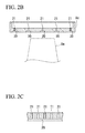
- FIG. 2B is a cross-sectional view along line A-A in FIG. 2A
- FIG. 2C is a cross-sectional view along line B-B in FIG. 2A .
- the shroud 8c is equipped with a groove portion 20 that is provided in the surface facing the turbine rotor blades 8a (the combustion gas passage surface), and a plurality of film cooling holes 21 that open to the bottom portion of the groove portion 20.
- the groove portion 20 is provided in the shape of a straight line with a constant depth from the combustion gas passage surface in the surface layer of the combustion gas passage surface of the shroud 8c, and is provided in a plurality at a regular interval.
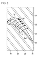
- FIG. 3 is a schematic view that shows the relation between the turbine rotor blade 8a and the groove portions 20. As shown in this drawing, the plurality of groove portions 20 are arrayed at a regular interval in the direction from the pressure side 8a2 to the suction side 8a1 of the turbine rotor blade 8a.
- the film cooling holes 21 are through holes that penetrate from the cooling air supply side of the shroud 8c to the bottom portion of the groove portion 20, and are provided in a plurality at a regular interval in the lengthwise direction of the groove portion 20. Cooling air is supplied from a cooling air supply portion that is not illustrated to each film cooling hole 21. Note that the cooling air supply portion, for example, bleeds compressed air from the high-pressure compressor 6, and supplies it to the film cooling holes 21 as cooling air.
- the cooling air that is supplied to the film cooling holes 21 leaves the film cooling holes 21, and flows along the combustion gas passage surface of the shroud 8c. Thereby, the shroud 8c is cooled.
- the groove portion 20 is provided in the surface of the shroud 8c, and the film cooling holes 21 are opened at the bottom portion of the groove portion 20. For this reason, even in the case of the turbine rotor blades 8a and the shroud 8c expanding due to thermal expansion, and the tips of the turbine rotor blades 8a rubbing against the combustion gas passage surface of the shroud 8c, it is possible to prevent the tips of the turbine rotor blades 8a from making contact with the openings of the film cooling holes 21. As a result, even in the case of melting occurring at the distal end portions of the turbine rotor blades 8a or the combustion gas passage surface of the shroud 8c during the rubbing, it is possible to prevent the melt product from blocking the film cooling hole 21.
- the groove portion 20 is arrayed in a plurality at a regular interval in the direction from the pressure side 8a2 to the suction side 8a1 of the turbine rotor blade 8a.
- a leakage flow R is produced from the high-pressure pressure side 8a2 to the suction side 8a1, between the tip of the turbine rotor blade 8a and the shroud 8c (refer to FIG. 3 ).
- the groove portion 20 is arrayed in a plurality at a regular interval in the direction from the pressure side 8a2 to the suction side 8a1 of the turbine rotor blade 8a, a labyrinth seal effect is produced, and it is possible to reduce the flow rate of the leakage flow R.
- the groove portion 20 extends in a direction perpendicular to the leakage flow R of the turbine rotor blade 8a, and is arrayed in a plurality in the direction of the leakage flow R.
- the plurality of groove portions 20 may either be arranged at a regular interval, or may not be arranged at a regular interval.
- the present invention is not limited to this, and as shown in FIG. 4A , it is also possible to adopt a constitution that arrays the film cooling holes 21 in a plurality of rows (three rows in FIG. 4A ) for one groove portion 20.
- film cooling holes 22 may be inclined so that the opening on the bottom portion side of the groove portion 20 is on the downstream of the leakage flow R with respect to the opening on cooling air supply side of the groove portion 20.
- the film cooling holes 22 are preferably inclined in a range of approximately 0 to 90 degrees with respect to the bottom portion of the groove portion 20.
- the film cooling hole 22 is more preferably inclined in a range of 0 to 75 degrees with respect to the bottom portion of the groove portion 20.
- groove portions are provided in the surface of the shroud, and film cooling holes are opened in the bottom portion of each of the groove portions. Accordingly, even in the case of rubbing, it is possible to prevent the tip of the turbine rotor blade from making contact with the openings of the film cooling holes. As a result, even in the case of melting of the distal end member of the rotor blade or the shroud material during rubbing, it is possible to prevent the melt product from blocking the film cooling holes.
Landscapes
- Engineering & Computer Science (AREA)
- Chemical & Material Sciences (AREA)
- Combustion & Propulsion (AREA)
- Mechanical Engineering (AREA)
- General Engineering & Computer Science (AREA)
- Turbine Rotor Nozzle Sealing (AREA)
- Structures Of Non-Positive Displacement Pumps (AREA)
Abstract
Description
- The present invention relates to a gas turbine engine.
- Priority is claimed on Japanese Patent Application No.
2012-043133, filed February 29, 2012 - In a gas turbine engine such as a turbo fan engine, a shroud is provided facing the turbine rotor blade. This shroud is arranged on the tip side of the turbine rotor blade, and constitutes a portion of a passage of a combustion gas that flows from a combustor to the turbine.
- Because the turbine rotor blade and the shroud are exposed to high-temperature combustion gas that is discharged from the combustor, a cooling mechanism is generally provided. For example, Patent Document 1 provides a turbine blade that is provided with film cooling holes that flow cooling air to a blade surface.
- [Patent Document 1] Japanese Unexamined Patent Application, First Publication No.
2002-227604 - In the case of cooling the shroud, it is conceivable to provide film cooling holes in the shroud in the manner of Patent Document 1 and adopt a structure that supplies cooling air to the surface of the shroud from the film cooling holes.
- However, due to thermal expansion, the turbine rotor blade and the shroud expand, and the tip of the turbine rotor blade may slightly graze (hereinbelow rub) the surface of the shroud. When the tip of the turbine rotor blade rubs against the surface of the shroud in this way, the distal end of the turbine rotor blade or the gas pass surface of the shroud melts due to frictional heat, which in the long run may lead to the film cooling holes being blocked.
- The present invention was achieved in view of the aforementioned circumstances. In a gas turbine engine that is provided with a shroud that is arranged facing a turbine rotor blade, the present invention has as its object to prevent the blocking of the film cooling holes that are provided in the shroud.
- The first aspect of the present invention is a gas turbine engine provided with a plurality of shrouds that are arranged facing the tip of a turbine rotor blade, in which each one of the shrouds is provided with a groove portion that is provided in the surface facing the turbine rotor blade, and a plurality of film cooling holes that open to the bottom portion of the groove portion.
- In the second aspect of the present invention, the groove portion in the aforementioned first aspect extends in a direction perpendicular to a leakage flow of the turbine rotor blade, and is arrayed in a plurality in the direction of the leakage flow.
- In the third aspect of the present invention, the film cooling holes in the aforementioned first or second aspect are inclined so that the opening on the bottom portion side of the groove portion is on the downstream side of the leakage flow with respect to the cooling air supply side of the opening.
- According to the present invention, groove portions are provided in the surface of a shroud, and film cooling holes are opened to the bottom portion of each of the groove portions. For this reason, even in the case of rubbing, it is possible to prevent the tip of the turbine rotor blade from making contact with the openings of the film cooling holes. As a result, even in the case of melting of the distal end member of the rotor blade or the shroud material during rubbing, it is possible to prevent the melt product from blocking the film cooling holes.
-
-
FIG. 1 is a cross-sectional view that shows the outline configuration of a turbofan engine in one embodiment of the present invention. -
FIG. 2A is a perspective view that shows a portion of a shroud that is provided in a turbofan engine in one embodiment of the present invention. -
FIG. 2B is a cross-sectional view along line A-A inFIG. 2A . -
FIG. 2C is a cross-sectional view along line B-B inFIG. 2A . -
FIG. 3 is a schematic view that shows the relation between a turbine rotor blade and a groove portions provided in a turbofan engine in one embodiment of the present invention. -
FIG. 4A is an outline view that shows a modification of a shroud that is provided in a turbofan engine in one embodiment of the present invention. -
FIG. 4B is a cross-sectional view that shows a modification of a shroud that is provided in a turbofan engine in one embodiment of the present invention. - Hereinbelow, one embodiment of a gas turbine engine according to the present invention shall be described, with reference to the drawings. Note that in the following drawings, the scale of each member is suitably altered in order to make each member a recognizable size. Also, in the following embodiment, the description is given for a turbofan engine that is one example of a gas turbine engine. However, the present invention is not limited to a turbofan engine, and can be applied to any gas turbine engine.
-
FIG. 1 is a cross-sectional view that shows the outline configuration of a turbofan engine 1 of the present embodiment. As shown in this drawing, the turbofan engine 1 of the present embodiment is provided with afan cowl 2, a core cowl 3, a fan 4, a low-pressure compressor 5, a high-pressure compressor 6, a combustor 7, a high-pressure turbine 8, a low-pressure turbine 9, ashaft 10, and amain nozzle 11. - The
fan cowl 2 is a tubular-type member that is arranged furthest to the upstream in the turbofan engine 1, with the upstream end and downstream end in the flow direction of the air serving as opening ends, and the upstream end functioning as an air intake. Also, thefan cowl 2 houses the upstream side of the core cowl 3 and the fan 4 in the inner portion thereof, as shown inFIG. 1 . - The core cowl 3 is a tubular-type member with a smaller diameter than the
fan cowl 2, and similarly to thefan cowl 2, the upstream end and downstream end in the flow direction of the air serve as opening ends. The core cowl 3 houses in the inner portion thereof the low-pressure compressor 5, the high-pressure compressor 6, the combustor 7, the high-pressure turbine 8, the low-pressure turbine 9, theshaft 10, and themain nozzle 11 and the like, which are the principal portions of the turbofan engine 1. - In the present embodiment, in the region where the core cowl 3 does not exist in the axial direction (the left-right direction of
FIG. 1 ), the internal space of thefan cowl 2 functions as aduct 12 through which the airflow flows, and in the region where the core cowl 3 does exist in the axial direction, the space sandwiched by thefan cowl 2 and the core cowl 3 functions as aduct 12 through which the airflow flows. - Note that the inner portion of the core cowl 3 serves as a passage (hereinbelow called a core passage) through which a portion of the air that is taken into the
fan cowl 2 and the combustion gas that is generated in the combustor 7 pass. Also, as shown inFIG. 1 , thefan cowl 2 and the core cowl 3 are arranged in the shape of concentric circles when viewed from the flow direction of air, with a gap arranged between them. The gap between thefan cowl 2 and the core cowl 3 is made to serve as a bypass passage that discharges to the outside the remainder of the air taken into thefan cowl 2 that does not flow into the core passage. Also, thefan cowl 2 and the core cowl 3 are attached to the fuselage or wings of an aircraft by pylons that are not illustrated. - The fan 4 forms the air flow that flows into the
fan cowl 2, and is provided with a plurality offan rotor blades 4a that are fixed to ashaft 10, and a plurality offan stator blades 4b that are arranged in the bypass passage. Note that theshaft 10, which is described in detail below, is divided into two in the radial direction, when viewed from the flow direction of the air. More precisely, theshaft 10 is constituted by a solidfirst shaft 10a that is the core, and a hollowsecond shaft 10b that is arranged on the outer side surrounding thefirst shaft 10a. Thefan rotor blades 4a are fixed to thefirst shaft 10a of theshaft 10. - As shown in
FIG. 1 , the low-pressure compressor 5 is arranged further to the upstream than the high-pressure compressor 6, and it compresses air that is sent into the core passage by the fan 4. The low-pressure compressor 5 is equipped withrotor blades 5a fixed to thefirst shaft 10a of theshaft 10, andstator blades 5b fixed to the inner wall of the core cowl 3. A blade lattice of one stage is formed by a plurality of thestator blades 5b arranged in an annular manner and a plurality of therotor blades 5a arranged in an annular manner to the downstream side thereof in the axial direction. The low-pressure compressor 5 is constituted by blade lattices of a plurality of stages being arranged in the axial direction. - As shown in
FIG. 1 , the high-pressure compressor 6 is arranged to the downstream of the low-pressure compressor 5, and compresses to a higher pressure the air sent in from the low-pressure compressor 5. The high-pressure compressor 6 is equipped withrotor blades 6a fixed to thesecond shaft 10b of theshaft 10, andstator blades 6b fixed to the inner wall of the core cowl 3. Note that in the same manner as the low-pressure compressor 5, a blade lattice of one stage is formed by a plurality of thestator blades 6b arranged in an annular manner and a plurality of therotor blades 6a arranged in an annular manner to the downstream side thereof in the axial direction. The high-pressure compressor 6 is constituted by blade lattices of a plurality of stages being arranged in the axial direction. - The combustor 7 is arranged at the downstream of the high-
pressure compressor 6, and generates combustion gas by burning an air-fuel mixture consisting of the compressed air sent in from the high-pressure compressor 6, and fuel supplied from a non-illustrated injector. - The high-
pressure turbine 8 is arranged at the downstream of the combustor 7, and recovers the rotative power from the combustion gas discharged from the combustor 7, and drives the high-pressure compressor 6. The high-pressure turbine 8 is equipped with a plurality ofturbine rotor blades 8a that are fixed to thesecond shaft 10b of theshaft 10, a plurality ofturbine stator vanes 8b that are fixed to the core passage, and shrouds 8c, and causes thesecond shaft 10b to rotate by receiving with theturbine rotor blades 8a the combustion gas that has been straightened by theturbine stator vanes 8b. Theshrouds 8c, which are provided facing the tip of theturbine rotor blades 8a, form a portion of the passage of the combustion gas discharged from the combustor 7. Theshrouds 8c shall be described in detail below. - The low-
pressure turbine 9 is arranged at the downstream of the high-pressure turbine 8, and further recovers rotative power from the combustion gas that passed the high-pressure turbine 8, and drives the fan 4 and the low-pressure compressor 5. The low-pressure turbine 9 is equipped with a plurality ofturbine rotor blades 9a that are fixed to thefirst shaft 10a of theshaft 10, a plurality ofturbine stator blades 9b that are fixed to the core passage, and shrouds 9c, and causes thefirst shaft 10a to rotate by receiving with theturbine rotor blades 9a the combustion gas that has been straightened by theturbine stator blades 9b. Theshrouds 9c form a portion of the passage of the combustion gas that is discharged from the combustor 7. If, similarly to theshrouds 8c of the high-pressure turbine, theshrouds 9c of the low-pressure turbine are provided facing the tip of theturbine rotor blades 9a, they are sometimes formed integrated with theturbine rotor blades 9a at the tip portion of theturbine rotor blades 9a. - The
shaft 10 is a rod-shaped member that is arranged facing the flow direction of air, and conveys the rotative force recovered by the turbines (the high-pressure turbine 8 and the low-pressure turbine 9) to the fan 4 and the compressors (the low-pressure compressor 5 and the high-pressure compressor 6). Theshaft 10, as mentioned above, is divided into two in the radial direction, to be constituted by thefirst shaft 10a and thesecond shaft 10b. Therotor blades 5a of the low-pressure compressor 5 and thefan rotor blades 4a of the fan 4 are attached to thefirst shaft 10a at the upstream, while theturbine rotor blades 9a of the low-pressure turbine 9 are attached at the downstream. Also, therotor blades 6a of the high-pressure compressor 6 are attached to thesecond shaft 10b at the upstream, and theturbine rotor blades 8a of the high-pressure turbine 8 are attached at the downstream. - The
main nozzle 11 is provided further to the downstream than the low-pressure turbine 9, and ejects combustion gas that has passed through the low-pressure turbine 9 toward the rear of the turbofan engine 1. The thrust of the turbofan engine 1 is obtained by the reaction when the combustion gas is ejected from themain nozzle 11. - Next, the
shroud 8c shall be described in greater detail, referring toFIG. 2A to FIG. 2C andFIG. 3 . Note that in the case of theshroud 9c of the low-pressure turbine having a form like theshroud 8c of the high-pressure turbine, although theshroud 9c of the low-pressure turbine is installed at a different position from theshroud 8c of the high-pressure turbine, its constitution is similar. For this reason, in the following description, theshroud 8c of the high-pressure turbine shall be described while referring to the drawings, with a description of theshroud 9c of the low-pressure turbine being omitted. - Hereinbelow, the
shroud 8c of the high-pressure turbine andshroud 9c of the low-pressure turbine shall be denoted simply as theshroud 8c and theshroud 9c. -
FIG. 2A is a perspective view that shows a portion of theshroud 8c.FIG. 2B is a cross-sectional view along line A-A inFIG. 2A , andFIG. 2C is a cross-sectional view along line B-B inFIG. 2A . As shown in these drawings, theshroud 8c is equipped with agroove portion 20 that is provided in the surface facing theturbine rotor blades 8a (the combustion gas passage surface), and a plurality of film cooling holes 21 that open to the bottom portion of thegroove portion 20. - The
groove portion 20 is provided in the shape of a straight line with a constant depth from the combustion gas passage surface in the surface layer of the combustion gas passage surface of theshroud 8c, and is provided in a plurality at a regular interval.FIG. 3 is a schematic view that shows the relation between theturbine rotor blade 8a and thegroove portions 20. As shown in this drawing, the plurality ofgroove portions 20 are arrayed at a regular interval in the direction from the pressure side 8a2 to the suction side 8a1 of theturbine rotor blade 8a. - The film cooling holes 21 are through holes that penetrate from the cooling air supply side of the
shroud 8c to the bottom portion of thegroove portion 20, and are provided in a plurality at a regular interval in the lengthwise direction of thegroove portion 20. Cooling air is supplied from a cooling air supply portion that is not illustrated to eachfilm cooling hole 21. Note that the cooling air supply portion, for example, bleeds compressed air from the high-pressure compressor 6, and supplies it to the film cooling holes 21 as cooling air. - The cooling air that is supplied to the film cooling holes 21 leaves the film cooling holes 21, and flows along the combustion gas passage surface of the
shroud 8c. Thereby, theshroud 8c is cooled. - In the turbofan engine 1 of the present embodiment as given above, the
groove portion 20 is provided in the surface of theshroud 8c, and the film cooling holes 21 are opened at the bottom portion of thegroove portion 20. For this reason, even in the case of theturbine rotor blades 8a and theshroud 8c expanding due to thermal expansion, and the tips of theturbine rotor blades 8a rubbing against the combustion gas passage surface of theshroud 8c, it is possible to prevent the tips of theturbine rotor blades 8a from making contact with the openings of the film cooling holes 21. As a result, even in the case of melting occurring at the distal end portions of theturbine rotor blades 8a or the combustion gas passage surface of theshroud 8c during the rubbing, it is possible to prevent the melt product from blocking thefilm cooling hole 21. - Also, in the turbofan engine 1 of the present embodiment, the
groove portion 20 is arrayed in a plurality at a regular interval in the direction from the pressure side 8a2 to the suction side 8a1 of theturbine rotor blade 8a. A leakage flow R is produced from the high-pressure pressure side 8a2 to the suction side 8a1, between the tip of theturbine rotor blade 8a and theshroud 8c (refer toFIG. 3 ). In contrast, since thegroove portion 20 is arrayed in a plurality at a regular interval in the direction from the pressure side 8a2 to the suction side 8a1 of theturbine rotor blade 8a, a labyrinth seal effect is produced, and it is possible to reduce the flow rate of the leakage flow R. That is, in the turbofan engine 1 of the present embodiment, thegroove portion 20 extends in a direction perpendicular to the leakage flow R of theturbine rotor blade 8a, and is arrayed in a plurality in the direction of the leakage flow R. - Note that the plurality of
groove portions 20 may either be arranged at a regular interval, or may not be arranged at a regular interval. - Hereinabove, the preferred embodiment of the present invention is described while referring to the appended drawings, but the present invention is not limited to the aforementioned embodiment. The various shapes and combinations of each constituent member shown in the embodiment refer to only a single example, and may be altered in various ways based on design requirements and so forth within a scope that does not deviate from the subject matter of the present invention.
- For example, in the aforementioned embodiment, a description is given for a constitution in which the film cooling holes 21 are arrayed in a row in the
groove portion 20. However, the present invention is not limited to this, and as shown inFIG. 4A , it is also possible to adopt a constitution that arrays the film cooling holes 21 in a plurality of rows (three rows inFIG. 4A ) for onegroove portion 20. - Also, as shown in
FIG. 4B , film cooling holes 22 may be inclined so that the opening on the bottom portion side of thegroove portion 20 is on the downstream of the leakage flow R with respect to the opening on cooling air supply side of thegroove portion 20. As for the inclination of the film cooling holes 22, the more it approaches being parallel with respect to the bottom portion of thegroove portion 20 the more it is preferable, since the cooling air that is ejected from the film cooling holes 22 flows along the leakage flow R. For example, the film cooling holes 22 are preferably inclined in a range of approximately 0 to 90 degrees with respect to the bottom portion of thegroove portion 20. Thefilm cooling hole 22 is more preferably inclined in a range of 0 to 75 degrees with respect to the bottom portion of thegroove portion 20. It is still more preferably inclined in a range of 0 to 45 degrees. By adopting the constitution of this kind of film cooling holes 22, since the cooling air is ejected out along the leakage flow R from the film cooling holes 22, it is possible to improve the adherence of the cooling air to the surface of theshroud 8c (9c), and improve the cooling effectiveness. - In a gas turbine engine that is provided with the shroud of the present invention, groove portions are provided in the surface of the shroud, and film cooling holes are opened in the bottom portion of each of the groove portions. Accordingly, even in the case of rubbing, it is possible to prevent the tip of the turbine rotor blade from making contact with the openings of the film cooling holes. As a result, even in the case of melting of the distal end member of the rotor blade or the shroud material during rubbing, it is possible to prevent the melt product from blocking the film cooling holes.
-
- 1:
- Turbofan engine (gas turbine engine)
- 2:
- Fan cowl
- 3:
- Core cowl
- 4:
- Fan
- 4a:
- Fan rotor blade
- 4b:
- Fan stator vane
- 5:
- Low-pressure compressor
- 5a:
- Rotor blade
- 5b:
- Stator vane
- 6:
- High-pressure compressor
- 6a:
- Rotor blade
- 6b:
- Stator vane
- 7:
- Combustor
- 8:
- High-pressure turbine
- 8a:
- Turbine rotor blade
- 8a1:
- Suction side
- 8a2:
- Pressure side
- 8b:
- Turbine stator vane
- 8c:
- Shroud
- 9:
- Low-pressure turbine
- 9a:
- Turbine rotor blade
- 9b:
- Turbine stator vane
- 9c:
- Shroud
- 10:
- Shaft
- 10a:
- First shaft
- 10b:
- Second shaft
- 11:
- Main nozzle
- 12:
- Duct
- 20:
- Groove portion
- 21:
- Film cooling hole
- 22:
- Film cooling hole
- R:
- Leakage flow
Claims (4)
- A gas turbine engine comprising a plurality of shrouds that are arranged facing the tip of a turbine rotor blade,
wherein each one of the shrouds comprises a groove portion that is provided in a surface facing the turbine rotor blade, and a plurality of film cooling holes that open to a bottom portion of the groove portion. - The gas turbine engine according to claim 1, wherein the groove portion extends in a direction perpendicular to a leakage flow of the turbine blade, and is arrayed in a plurality in the direction of the leakage flow.
- The gas turbine engine according to claim 1, wherein the film cooling holes are inclined so that the opening on the bottom portion side of the groove portion is on the downstream of the leakage flow with respect to the opening on the cooling air supply side of the groove portion.
- The gas turbine engine according to claim 2, wherein the film cooling holes are inclined so that the opening on the bottom portion side of the groove portion is on the downstream of the leakage flow with respect to the opening on the cooling air supply side of the groove portion.
Applications Claiming Priority (2)
| Application Number | Priority Date | Filing Date | Title |
|---|---|---|---|
| JP2012043133A JP2013177875A (en) | 2012-02-29 | 2012-02-29 | Gas turbine engine |
| PCT/JP2013/055247 WO2013129530A1 (en) | 2012-02-29 | 2013-02-27 | Gas turbine engine |
Publications (3)
| Publication Number | Publication Date |
|---|---|
| EP2821622A1 true EP2821622A1 (en) | 2015-01-07 |
| EP2821622A4 EP2821622A4 (en) | 2015-11-11 |
| EP2821622B1 EP2821622B1 (en) | 2018-09-05 |
Family
ID=49082724
Family Applications (1)
| Application Number | Title | Priority Date | Filing Date |
|---|---|---|---|
| EP13755339.2A Active EP2821622B1 (en) | 2012-02-29 | 2013-02-27 | Gas turbine engine |
Country Status (7)
| Country | Link |
|---|---|
| US (1) | US20140366545A1 (en) |
| EP (1) | EP2821622B1 (en) |
| JP (1) | JP2013177875A (en) |
| KR (1) | KR20140124799A (en) |
| CN (1) | CN104126065B (en) |
| CA (1) | CA2865878C (en) |
| WO (1) | WO2013129530A1 (en) |
Families Citing this family (5)
| Publication number | Priority date | Publication date | Assignee | Title |
|---|---|---|---|---|
| KR101839656B1 (en) | 2015-08-13 | 2018-04-26 | 두산중공업 주식회사 | Blade for turbine |
| RU2706210C2 (en) | 2016-01-25 | 2019-11-14 | Ансалдо Энерджиа Свитзерлэнд Аг | Stator thermal shield for gas turbine, gas turbine with such stator thermal shield and stator thermal shield cooling method |
| US10830082B2 (en) * | 2017-05-10 | 2020-11-10 | General Electric Company | Systems including rotor blade tips and circumferentially grooved shrouds |
| US12123319B2 (en) | 2020-12-30 | 2024-10-22 | Ge Infrastructure Technology Llc | Cooling circuit having a bypass conduit for a turbomachine component |
| CN112780355B (en) * | 2021-02-25 | 2022-12-06 | 哈尔滨工业大学 | A divergent cooling air film hole distribution structure of a supersonic turbine blade |
Family Cites Families (14)
| Publication number | Priority date | Publication date | Assignee | Title |
|---|---|---|---|---|
| US3365172A (en) * | 1966-11-02 | 1968-01-23 | Gen Electric | Air cooled shroud seal |
| US4157880A (en) * | 1977-09-16 | 1979-06-12 | General Electric Company | Turbine rotor tip water collector |
| JPS62153504A (en) * | 1985-12-26 | 1987-07-08 | Toshiba Corp | Shrouding segment |
| WO1994012775A1 (en) * | 1992-11-24 | 1994-06-09 | United Technologies Corporation | Coolable outer air seal assembly for a turbine |
| US5649806A (en) * | 1993-11-22 | 1997-07-22 | United Technologies Corporation | Enhanced film cooling slot for turbine blade outer air seals |
| US6155778A (en) * | 1998-12-30 | 2000-12-05 | General Electric Company | Recessed turbine shroud |
| JP2005042616A (en) * | 2003-07-22 | 2005-02-17 | Ishikawajima Harima Heavy Ind Co Ltd | Shroud segment |
| US7665961B2 (en) * | 2006-11-28 | 2010-02-23 | United Technologies Corporation | Turbine outer air seal |
| GB2444501B (en) * | 2006-12-06 | 2009-01-28 | Siemens Ag | A gas turbine |
| US7988410B1 (en) * | 2007-11-19 | 2011-08-02 | Florida Turbine Technologies, Inc. | Blade tip shroud with circular grooves |
| US8371800B2 (en) * | 2010-03-03 | 2013-02-12 | General Electric Company | Cooling gas turbine components with seal slot channels |
| US20120114868A1 (en) * | 2010-11-10 | 2012-05-10 | General Electric Company | Method of fabricating a component using a fugitive coating |
| US9022737B2 (en) * | 2011-08-08 | 2015-05-05 | United Technologies Corporation | Airfoil including trench with contoured surface |
| GB201205663D0 (en) * | 2012-03-30 | 2012-05-16 | Rolls Royce Plc | Effusion cooled shroud segment with an abradable system |
-
2012
- 2012-02-29 JP JP2012043133A patent/JP2013177875A/en active Pending
-
2013
- 2013-02-27 CN CN201380011169.0A patent/CN104126065B/en active Active
- 2013-02-27 CA CA2865878A patent/CA2865878C/en active Active
- 2013-02-27 KR KR1020147023826A patent/KR20140124799A/en not_active Ceased
- 2013-02-27 EP EP13755339.2A patent/EP2821622B1/en active Active
- 2013-02-27 WO PCT/JP2013/055247 patent/WO2013129530A1/en not_active Ceased
-
2014
- 2014-08-28 US US14/471,170 patent/US20140366545A1/en not_active Abandoned
Also Published As
| Publication number | Publication date |
|---|---|
| KR20140124799A (en) | 2014-10-27 |
| CA2865878A1 (en) | 2013-09-06 |
| US20140366545A1 (en) | 2014-12-18 |
| CN104126065A (en) | 2014-10-29 |
| EP2821622A4 (en) | 2015-11-11 |
| CA2865878C (en) | 2017-04-04 |
| EP2821622B1 (en) | 2018-09-05 |
| JP2013177875A (en) | 2013-09-09 |
| CN104126065B (en) | 2016-04-06 |
| WO2013129530A1 (en) | 2013-09-06 |
Similar Documents
| Publication | Publication Date | Title |
|---|---|---|
| US11466579B2 (en) | Turbine engine airfoil and method | |
| EP2666964A2 (en) | Gas turbine engine blades with cooling hole trenches | |
| EP4105442B1 (en) | Improved cooling schemes for airfoils for gas turbine engines | |
| JP2009108861A (en) | Asymmetric flow extraction system | |
| EP3205816A1 (en) | Impingement holes for a turbine engine component | |
| EP3091184A1 (en) | Turbine airfoil leading edge cooling | |
| EP3255248A1 (en) | Engine component for a turbine engine | |
| EP2821622B1 (en) | Gas turbine engine | |
| EP3034793B1 (en) | Gas turbine engine component with increased cooling capacity | |
| CA2921249A1 (en) | Engine component | |
| JP2017082766A (en) | Ceramic matrix composite ring shroud holding method and CMC pin head | |
| US20180231026A1 (en) | Turbine engine compressor with a cooling circuit | |
| US20180252108A1 (en) | Staggered core printout | |
| EP3054093B1 (en) | Arrangement of trip strips | |
| US20180135452A1 (en) | Airfoil with panel having perimeter seal | |
| EP2791472B2 (en) | Film cooled turbine component | |
| EP3176376B1 (en) | Cooling passages for a gas path component of a gas turbine engine | |
| EP3101236B1 (en) | Trailing edge platform seals | |
| EP3301261B1 (en) | Blade | |
| CN107084006A (en) | Accelerator insert for gas-turbine unit airfoil | |
| EP2946081B1 (en) | Variable area vane arrangement for a turbine engine | |
| JP4446150B2 (en) | Gas turbine purge air blowing method and blowing structure | |
| CN114251132A (en) | Gas turbine engine rotor blade with metallic structural member and composite fairing | |
| US20180135444A1 (en) | Airfoil with retention pocket holding airfoil piece |
Legal Events
| Date | Code | Title | Description |
|---|---|---|---|
| PUAI | Public reference made under article 153(3) epc to a published international application that has entered the european phase |
Free format text: ORIGINAL CODE: 0009012 |
|
| 17P | Request for examination filed |
Effective date: 20140910 |
|
| AK | Designated contracting states |
Kind code of ref document: A1 Designated state(s): AL AT BE BG CH CY CZ DE DK EE ES FI FR GB GR HR HU IE IS IT LI LT LU LV MC MK MT NL NO PL PT RO RS SE SI SK SM TR |
|
| AX | Request for extension of the european patent |
Extension state: BA ME |
|
| DAX | Request for extension of the european patent (deleted) | ||
| RA4 | Supplementary search report drawn up and despatched (corrected) |
Effective date: 20151009 |
|
| RIC1 | Information provided on ipc code assigned before grant |
Ipc: F01D 25/12 20060101ALI20151005BHEP Ipc: F01D 11/10 20060101ALI20151005BHEP Ipc: F01D 25/24 20060101ALI20151005BHEP Ipc: F02C 7/18 20060101AFI20151005BHEP |
|
| GRAP | Despatch of communication of intention to grant a patent |
Free format text: ORIGINAL CODE: EPIDOSNIGR1 |
|
| STAA | Information on the status of an ep patent application or granted ep patent |
Free format text: STATUS: GRANT OF PATENT IS INTENDED |
|
| INTG | Intention to grant announced |
Effective date: 20180509 |
|
| GRAS | Grant fee paid |
Free format text: ORIGINAL CODE: EPIDOSNIGR3 |
|
| GRAA | (expected) grant |
Free format text: ORIGINAL CODE: 0009210 |
|
| STAA | Information on the status of an ep patent application or granted ep patent |
Free format text: STATUS: THE PATENT HAS BEEN GRANTED |
|
| AK | Designated contracting states |
Kind code of ref document: B1 Designated state(s): AL AT BE BG CH CY CZ DE DK EE ES FI FR GB GR HR HU IE IS IT LI LT LU LV MC MK MT NL NO PL PT RO RS SE SI SK SM TR |
|
| REG | Reference to a national code |
Ref country code: GB Ref legal event code: FG4D |
|
| REG | Reference to a national code |
Ref country code: CH Ref legal event code: EP |
|
| REG | Reference to a national code |
Ref country code: AT Ref legal event code: REF Ref document number: 1038077 Country of ref document: AT Kind code of ref document: T Effective date: 20180915 |
|
| REG | Reference to a national code |
Ref country code: IE Ref legal event code: FG4D |
|
| REG | Reference to a national code |
Ref country code: DE Ref legal event code: R096 Ref document number: 602013043173 Country of ref document: DE |
|
| REG | Reference to a national code |
Ref country code: NL Ref legal event code: MP Effective date: 20180905 |
|
| REG | Reference to a national code |
Ref country code: LT Ref legal event code: MG4D |
|
| PG25 | Lapsed in a contracting state [announced via postgrant information from national office to epo] |
Ref country code: GR Free format text: LAPSE BECAUSE OF FAILURE TO SUBMIT A TRANSLATION OF THE DESCRIPTION OR TO PAY THE FEE WITHIN THE PRESCRIBED TIME-LIMIT Effective date: 20181206 Ref country code: NO Free format text: LAPSE BECAUSE OF FAILURE TO SUBMIT A TRANSLATION OF THE DESCRIPTION OR TO PAY THE FEE WITHIN THE PRESCRIBED TIME-LIMIT Effective date: 20181205 Ref country code: FI Free format text: LAPSE BECAUSE OF FAILURE TO SUBMIT A TRANSLATION OF THE DESCRIPTION OR TO PAY THE FEE WITHIN THE PRESCRIBED TIME-LIMIT Effective date: 20180905 Ref country code: SE Free format text: LAPSE BECAUSE OF FAILURE TO SUBMIT A TRANSLATION OF THE DESCRIPTION OR TO PAY THE FEE WITHIN THE PRESCRIBED TIME-LIMIT Effective date: 20180905 Ref country code: LT Free format text: LAPSE BECAUSE OF FAILURE TO SUBMIT A TRANSLATION OF THE DESCRIPTION OR TO PAY THE FEE WITHIN THE PRESCRIBED TIME-LIMIT Effective date: 20180905 Ref country code: RS Free format text: LAPSE BECAUSE OF FAILURE TO SUBMIT A TRANSLATION OF THE DESCRIPTION OR TO PAY THE FEE WITHIN THE PRESCRIBED TIME-LIMIT Effective date: 20180905 Ref country code: BG Free format text: LAPSE BECAUSE OF FAILURE TO SUBMIT A TRANSLATION OF THE DESCRIPTION OR TO PAY THE FEE WITHIN THE PRESCRIBED TIME-LIMIT Effective date: 20181205 |
|
| REG | Reference to a national code |
Ref country code: AT Ref legal event code: MK05 Ref document number: 1038077 Country of ref document: AT Kind code of ref document: T Effective date: 20180905 |
|
| PG25 | Lapsed in a contracting state [announced via postgrant information from national office to epo] |
Ref country code: AL Free format text: LAPSE BECAUSE OF FAILURE TO SUBMIT A TRANSLATION OF THE DESCRIPTION OR TO PAY THE FEE WITHIN THE PRESCRIBED TIME-LIMIT Effective date: 20180905 Ref country code: LV Free format text: LAPSE BECAUSE OF FAILURE TO SUBMIT A TRANSLATION OF THE DESCRIPTION OR TO PAY THE FEE WITHIN THE PRESCRIBED TIME-LIMIT Effective date: 20180905 Ref country code: HR Free format text: LAPSE BECAUSE OF FAILURE TO SUBMIT A TRANSLATION OF THE DESCRIPTION OR TO PAY THE FEE WITHIN THE PRESCRIBED TIME-LIMIT Effective date: 20180905 |
|
| PG25 | Lapsed in a contracting state [announced via postgrant information from national office to epo] |
Ref country code: NL Free format text: LAPSE BECAUSE OF FAILURE TO SUBMIT A TRANSLATION OF THE DESCRIPTION OR TO PAY THE FEE WITHIN THE PRESCRIBED TIME-LIMIT Effective date: 20180905 Ref country code: EE Free format text: LAPSE BECAUSE OF FAILURE TO SUBMIT A TRANSLATION OF THE DESCRIPTION OR TO PAY THE FEE WITHIN THE PRESCRIBED TIME-LIMIT Effective date: 20180905 Ref country code: PL Free format text: LAPSE BECAUSE OF FAILURE TO SUBMIT A TRANSLATION OF THE DESCRIPTION OR TO PAY THE FEE WITHIN THE PRESCRIBED TIME-LIMIT Effective date: 20180905 Ref country code: IS Free format text: LAPSE BECAUSE OF FAILURE TO SUBMIT A TRANSLATION OF THE DESCRIPTION OR TO PAY THE FEE WITHIN THE PRESCRIBED TIME-LIMIT Effective date: 20190105 Ref country code: AT Free format text: LAPSE BECAUSE OF FAILURE TO SUBMIT A TRANSLATION OF THE DESCRIPTION OR TO PAY THE FEE WITHIN THE PRESCRIBED TIME-LIMIT Effective date: 20180905 Ref country code: ES Free format text: LAPSE BECAUSE OF FAILURE TO SUBMIT A TRANSLATION OF THE DESCRIPTION OR TO PAY THE FEE WITHIN THE PRESCRIBED TIME-LIMIT Effective date: 20180905 Ref country code: CZ Free format text: LAPSE BECAUSE OF FAILURE TO SUBMIT A TRANSLATION OF THE DESCRIPTION OR TO PAY THE FEE WITHIN THE PRESCRIBED TIME-LIMIT Effective date: 20180905 Ref country code: RO Free format text: LAPSE BECAUSE OF FAILURE TO SUBMIT A TRANSLATION OF THE DESCRIPTION OR TO PAY THE FEE WITHIN THE PRESCRIBED TIME-LIMIT Effective date: 20180905 |
|
| PG25 | Lapsed in a contracting state [announced via postgrant information from national office to epo] |
Ref country code: PT Free format text: LAPSE BECAUSE OF FAILURE TO SUBMIT A TRANSLATION OF THE DESCRIPTION OR TO PAY THE FEE WITHIN THE PRESCRIBED TIME-LIMIT Effective date: 20190105 Ref country code: SM Free format text: LAPSE BECAUSE OF FAILURE TO SUBMIT A TRANSLATION OF THE DESCRIPTION OR TO PAY THE FEE WITHIN THE PRESCRIBED TIME-LIMIT Effective date: 20180905 Ref country code: SK Free format text: LAPSE BECAUSE OF FAILURE TO SUBMIT A TRANSLATION OF THE DESCRIPTION OR TO PAY THE FEE WITHIN THE PRESCRIBED TIME-LIMIT Effective date: 20180905 |
|
| REG | Reference to a national code |
Ref country code: DE Ref legal event code: R097 Ref document number: 602013043173 Country of ref document: DE |
|
| PLBE | No opposition filed within time limit |
Free format text: ORIGINAL CODE: 0009261 |
|
| STAA | Information on the status of an ep patent application or granted ep patent |
Free format text: STATUS: NO OPPOSITION FILED WITHIN TIME LIMIT |
|
| PG25 | Lapsed in a contracting state [announced via postgrant information from national office to epo] |
Ref country code: DK Free format text: LAPSE BECAUSE OF FAILURE TO SUBMIT A TRANSLATION OF THE DESCRIPTION OR TO PAY THE FEE WITHIN THE PRESCRIBED TIME-LIMIT Effective date: 20180905 |
|
| 26N | No opposition filed |
Effective date: 20190606 |
|
| PG25 | Lapsed in a contracting state [announced via postgrant information from national office to epo] |
Ref country code: SI Free format text: LAPSE BECAUSE OF FAILURE TO SUBMIT A TRANSLATION OF THE DESCRIPTION OR TO PAY THE FEE WITHIN THE PRESCRIBED TIME-LIMIT Effective date: 20180905 |
|
| REG | Reference to a national code |
Ref country code: CH Ref legal event code: PL |
|
| PG25 | Lapsed in a contracting state [announced via postgrant information from national office to epo] |
Ref country code: MC Free format text: LAPSE BECAUSE OF FAILURE TO SUBMIT A TRANSLATION OF THE DESCRIPTION OR TO PAY THE FEE WITHIN THE PRESCRIBED TIME-LIMIT Effective date: 20180905 Ref country code: LU Free format text: LAPSE BECAUSE OF NON-PAYMENT OF DUE FEES Effective date: 20190227 |
|
| REG | Reference to a national code |
Ref country code: BE Ref legal event code: MM Effective date: 20190228 |
|
| REG | Reference to a national code |
Ref country code: IE Ref legal event code: MM4A |
|
| PG25 | Lapsed in a contracting state [announced via postgrant information from national office to epo] |
Ref country code: CH Free format text: LAPSE BECAUSE OF NON-PAYMENT OF DUE FEES Effective date: 20190228 Ref country code: LI Free format text: LAPSE BECAUSE OF NON-PAYMENT OF DUE FEES Effective date: 20190228 |
|
| PG25 | Lapsed in a contracting state [announced via postgrant information from national office to epo] |
Ref country code: IE Free format text: LAPSE BECAUSE OF NON-PAYMENT OF DUE FEES Effective date: 20190227 |
|
| PG25 | Lapsed in a contracting state [announced via postgrant information from national office to epo] |
Ref country code: BE Free format text: LAPSE BECAUSE OF NON-PAYMENT OF DUE FEES Effective date: 20190228 |
|
| PG25 | Lapsed in a contracting state [announced via postgrant information from national office to epo] |
Ref country code: TR Free format text: LAPSE BECAUSE OF FAILURE TO SUBMIT A TRANSLATION OF THE DESCRIPTION OR TO PAY THE FEE WITHIN THE PRESCRIBED TIME-LIMIT Effective date: 20180905 |
|
| PG25 | Lapsed in a contracting state [announced via postgrant information from national office to epo] |
Ref country code: MT Free format text: LAPSE BECAUSE OF NON-PAYMENT OF DUE FEES Effective date: 20190227 |
|
| PG25 | Lapsed in a contracting state [announced via postgrant information from national office to epo] |
Ref country code: CY Free format text: LAPSE BECAUSE OF FAILURE TO SUBMIT A TRANSLATION OF THE DESCRIPTION OR TO PAY THE FEE WITHIN THE PRESCRIBED TIME-LIMIT Effective date: 20180905 |
|
| PG25 | Lapsed in a contracting state [announced via postgrant information from national office to epo] |
Ref country code: HU Free format text: LAPSE BECAUSE OF FAILURE TO SUBMIT A TRANSLATION OF THE DESCRIPTION OR TO PAY THE FEE WITHIN THE PRESCRIBED TIME-LIMIT; INVALID AB INITIO Effective date: 20130227 |
|
| PG25 | Lapsed in a contracting state [announced via postgrant information from national office to epo] |
Ref country code: MK Free format text: LAPSE BECAUSE OF FAILURE TO SUBMIT A TRANSLATION OF THE DESCRIPTION OR TO PAY THE FEE WITHIN THE PRESCRIBED TIME-LIMIT Effective date: 20180905 |
|
| PGFP | Annual fee paid to national office [announced via postgrant information from national office to epo] |
Ref country code: GB Payment date: 20260121 Year of fee payment: 14 |
|
| PGFP | Annual fee paid to national office [announced via postgrant information from national office to epo] |
Ref country code: DE Payment date: 20260121 Year of fee payment: 14 |
|
| PGFP | Annual fee paid to national office [announced via postgrant information from national office to epo] |
Ref country code: IT Payment date: 20260121 Year of fee payment: 14 |
|
| PGFP | Annual fee paid to national office [announced via postgrant information from national office to epo] |
Ref country code: FR Payment date: 20260121 Year of fee payment: 14 |