EP2821581A1 - Einbauelement - Google Patents
Einbauelement Download PDFInfo
- Publication number
- EP2821581A1 EP2821581A1 EP14001841.7A EP14001841A EP2821581A1 EP 2821581 A1 EP2821581 A1 EP 2821581A1 EP 14001841 A EP14001841 A EP 14001841A EP 2821581 A1 EP2821581 A1 EP 2821581A1
- Authority
- EP
- European Patent Office
- Prior art keywords
- wall
- region
- blocking region
- mounting element
- profile
- Prior art date
- Legal status (The legal status is an assumption and is not a legal conclusion. Google has not performed a legal analysis and makes no representation as to the accuracy of the status listed.)
- Granted
Links
Images




Classifications
-
- E—FIXED CONSTRUCTIONS
- E06—DOORS, WINDOWS, SHUTTERS, OR ROLLER BLINDS IN GENERAL; LADDERS
- E06B—FIXED OR MOVABLE CLOSURES FOR OPENINGS IN BUILDINGS, VEHICLES, FENCES OR LIKE ENCLOSURES IN GENERAL, e.g. DOORS, WINDOWS, BLINDS, GATES
- E06B5/00—Doors, windows, or like closures for special purposes; Border constructions therefor
- E06B5/10—Doors, windows, or like closures for special purposes; Border constructions therefor for protection against air-raid or other war-like action; for other protective purposes
- E06B5/11—Doors, windows, or like closures for special purposes; Border constructions therefor for protection against air-raid or other war-like action; for other protective purposes against burglary
- E06B5/113—Arrangements at the edges of the wings, e.g. with door guards to prevent the insertion of prying tools
-
- E—FIXED CONSTRUCTIONS
- E06—DOORS, WINDOWS, SHUTTERS, OR ROLLER BLINDS IN GENERAL; LADDERS
- E06B—FIXED OR MOVABLE CLOSURES FOR OPENINGS IN BUILDINGS, VEHICLES, FENCES OR LIKE ENCLOSURES IN GENERAL, e.g. DOORS, WINDOWS, BLINDS, GATES
- E06B1/00—Border constructions of openings in walls, floors, or ceilings; Frames to be rigidly mounted in such openings
- E06B1/56—Fastening frames to the border of openings or to similar contiguous frames
- E06B1/60—Fastening frames to the border of openings or to similar contiguous frames by mechanical means, e.g. anchoring means
- E06B1/6015—Anchoring means
-
- E—FIXED CONSTRUCTIONS
- E04—BUILDING
- E04B—GENERAL BUILDING CONSTRUCTIONS; WALLS, e.g. PARTITIONS; ROOFS; FLOORS; CEILINGS; INSULATION OR OTHER PROTECTION OF BUILDINGS
- E04B2/00—Walls, e.g. partitions, for buildings; Wall construction with regard to insulation; Connections specially adapted to walls
- E04B2/88—Curtain walls
- E04B2/90—Curtain walls comprising panels directly attached to the structure
-
- E—FIXED CONSTRUCTIONS
- E06—DOORS, WINDOWS, SHUTTERS, OR ROLLER BLINDS IN GENERAL; LADDERS
- E06B—FIXED OR MOVABLE CLOSURES FOR OPENINGS IN BUILDINGS, VEHICLES, FENCES OR LIKE ENCLOSURES IN GENERAL, e.g. DOORS, WINDOWS, BLINDS, GATES
- E06B3/00—Window sashes, door leaves, or like elements for closing wall or like openings; Layout of fixed or moving closures, e.g. windows in wall or like openings; Features of rigidly-mounted outer frames relating to the mounting of wing frames
- E06B3/54—Fixing of glass panes or like plates
- E06B3/5454—Fixing of glass panes or like plates inside U-shaped section members
-
- E—FIXED CONSTRUCTIONS
- E06—DOORS, WINDOWS, SHUTTERS, OR ROLLER BLINDS IN GENERAL; LADDERS
- E06B—FIXED OR MOVABLE CLOSURES FOR OPENINGS IN BUILDINGS, VEHICLES, FENCES OR LIKE ENCLOSURES IN GENERAL, e.g. DOORS, WINDOWS, BLINDS, GATES
- E06B3/00—Window sashes, door leaves, or like elements for closing wall or like openings; Layout of fixed or moving closures, e.g. windows in wall or like openings; Features of rigidly-mounted outer frames relating to the mounting of wing frames
- E06B3/54—Fixing of glass panes or like plates
- E06B3/58—Fixing of glass panes or like plates by means of borders, cleats, or the like
- E06B3/5892—Fixing of window panes in openings in door leaves
Definitions
- the invention relates to a built-in element for separating an interior of an exterior space with a fixed element having an end portion, and with a wall connection for fixing the fixed element to a wall.
- the wall connection has side parts for receiving the end region and at least one wall part for fastening the wall connection to the wall according to the preamble of claim 1.
- Known mounting elements have a wall connection, which is formed as a U-profile, as in FIG. 2a shown.
- a burglar may bend the side panel facing the exterior, as in FIG. 2b shown. The burglar can then lever out the fixed element and remove it in the direction of the outside space. This allows the burglar to gain access to the interior within a short time.
- the wall connection is designed such that after bending of a side part of the wall connection a blocking region which is ragbar into a recess of the end portion.
- the end region of the stationary element is received in the wall connection.
- the blocking region protrudes into the recess of the end region in the mounted state. That is, the blocking portion engages the recess of the end portion without having to touch the end portion.
- the end region and the wall connection are thus matched to one another before installation so that after the assembly of the installation element and after bending of the side part the blocking region projects into the recess.
- the end region and the blocking region enter into a positive connection.
- the blocking region holds the end region in a form-fitting manner during movement of the stationary element in the direction of the external space.
- removal of the fixed member in the direction of the outside space is prevented. Therefore, a burglar can not gain access to the interior.
- the burglary protection is thus improved.
- the burglary protection of the RC3 resistance class of the European standard EN 1627 can be achieved with the present invention.
- RC3 resistance class If the RC3 resistance class is met, a familiar perpetrator tries in vain to break up the installation element within five minutes, not only with simple tools such as a screwdriver, pliers or a wedge, but also with a second screwdriver and a cow's foot.
- the burglar tries to gain access to the interior from the outside space.
- exterior and interior designate the direction in which a burglar attempts to gain access.
- exterior and interior do not include whether the exterior and / or interior is covered. Rather, the exterior and the interior z. B. both be covered.
- the fixed element may be a door element or a window element, e.g. B. a skylight, his.
- the installation element may still have at least one further door or window element.
- the further door or window element can be movable.
- the fixed member is part of a sliding door assembly.
- the installation element may correspond to the sliding door arrangement.
- the movable door element is designed as a sliding door and can partially overlap the fixed element in the open state. It is conceivable that the sliding door arrangement can be opened manually or automatically by non-contact sensors.
- the fixed element and / or, if appropriate, the movable door of the window element may comprise a glass pane.
- the end portion of the fixed member may correspond to a socket of the glass sheet.
- the side panels serve to at least partially accommodate the end portion between the side panels.
- the wall connection can be used to compensate for building tolerances of the wall.
- the wall connection can serve in particular for fastening the fixed element to a lateral wall. It is also conceivable that the wall connection additionally or alternatively for attachment to an upper and / or lower wall serves.
- a first region of the wall part can be designed as an abutment area for abutment against the wall or on another wall part.
- the side part after bending one of the two side parts of the blocking region is present, while after bending over the other side part no blocking region is present.
- the side part after the bending of the wall region has a blocking region which can be projected into the recess, is in particular the side part facing the exterior in the mounted state.
- the wall connection does not have to have the blocking area projecting into the recess only after the side part has been bent over.
- the invention also incorporates mounting elements whose wall connection already has a blocking region which can be projected into the recess prior to bending over.
- the blocking region which can be projected into the recess must be present at least after the side part has been bent over. That is, at the latest, when the burglar has bent the side part, the blocking area is present and blocks a levering out of the fixed element.
- the blocking area is present even before bending over.
- the blocking region is prefabricated, in particular pre-punched, already present during assembly of the installation element.
- the blocking area can be punched during manufacture of the installation element.
- the blocking area arises during the bending of the side part. That is, in the bending of the side part at the same time a portion of the wall connection is mitverbogen, which serves as a blocking area after bending.
- the blocking region is formed as a monolithic region of the wall part and / or at least one side part.
- a second region of a wall part is designed as a blocking region.
- the blocking region and the contact region can be monolithic. This material can be saved. If the blocking area arises only when the side part is bent over, then the second area is designed to be bendable.
- a receiving space may be formed in the assembled state of the mounting element of the contact area and the side parts for receiving the end portion and the blocking region may protrude in the assembled state in the receiving space.
- the blocking portion has a first end projecting into the recess and a second end connected to the remainder of the wallport.
- the second end of the blocking region can be arranged on the contact area or in the vicinity of the contact area.
- the blocking area can run obliquely into the receiving space. In the direction of the outer space, the blocking area is accordingly as Barbs trained. As a result, embracing the blocking area is made more difficult for the burglar.
- the blocking region extends arcuately from the first end of the blocking region to the second end of the blocking region. That is, the blocking region is formed in an arcuate in a perpendicular to a side part and the contact area extending cross-section. As a result, the blocking area can absorb forces particularly well.
- the blocking region does not protrude into the recess over the entire length along the longitudinal direction of the wall connection. It is sufficient for the blocking region to be designed in such a way that the blocking region can be projected into the recess only at one point.
- the blocking region is ragbar in several places in the recess. Particularly preferably, the multiple locations are distributed over the entire length of the wall connection. As a result, the burglar is particularly difficult to remove the fixed element.
- the blocking region may be interrupted in the longitudinal direction.
- the blocking region is wave-shaped in the longitudinal direction of the wall connection.
- at least one wave crest of the blocking region is designed to be able to project into the recess.
- Several wave crests preferably protrude, and particularly preferably all wave crests protrude into the recess.
- the undulating blocking area can be created by simple bending and is therefore particularly easy to produce.
- the blocking region may be wave-shaped if the blocking region is created when the side part is bent over.
- the blocking region is formed in the longitudinal direction of the wall connection parallel to the contact region. In this way, a particularly large part of the blocking region projects into the recess in the longitudinal direction of the wall connection.
- the blocking region is interrupted in the longitudinal direction of the wall connection by at least one fastening region.
- the attachment area is the part of the investment area, which allows the attachment of the wall connection to the wall.
- the attachment area may include a recess for passing through a fastener.
- the fastener may be, for example, a screw which is held through the recess in a dowel in the wall.
- the attachment areas have a distance of 30 to 50 cm.
- the blocking region can be arranged at least partially at the same depth as the at least one fastening region. That is, the blocking area and the fixing area alternate along the longitudinal direction of the wall terminal. As a result, even with a small depth of the wall connection of the blocking region can be realized.
- the blocking region may have the same wall thickness as the wall part and / or the side part. Due to the selection of materials and / or the wall thickness, the side parts can be made umbiegbar. By the choice of material and / or the wall thickness, the blocking region may have sufficient strength to hold the fixed element. Due to a small wall thickness, the blocking area can occur when bending the side panels.
- the blocking region, the wall part and / or the side parts may be made of steel, in particular stainless steel.
- the blocking region, the wall part and / or the side part may have a wall thickness of 2 to 3 mm.
- At least one wall part and one side part are monolithic.
- the wall connection comprises two L-profiles. In each case one leg of an L-profile forms a side part and one leg of an L-profile forms a wall part. As a result, simple moldings can be used.
- the legs of both L-profiles which form the wall part, can be arranged facing each other, in particular overlapping, be arranged.
- the recesses of the two wall parts may overlap, so that in each case one fastening element can be guided by a respective recess of both wall parts.
- the wall part of the L-profile which also includes the side part directed toward the exterior, is preferably arranged above the wall part of the L-profile, which comprises the side part directed towards the interior.
- the L-profiles have the same orientation as a leg of an L-profile, which forms a wall portion which points into the interior. This arrangement is particularly easy to install.
- the wall connection may alternatively comprise a U-profile, wherein the side parts and the wall part form the U-profile.
- the U-profile can be provided in particular if the blocking area is prefabricated.
- at least one slot preferably a plurality of slots may be provided which make the second region of the wall portion of the U-profile at a bend of a side part bendable.
- the end portion may be made of aluminum.
- the part of the end region which surrounds the recess can be designed U-profile-like, wherein in each case one leg of the U-shaped-like part is formed for internal contact with the side parts. If the end region is designed as a socket, the end region can be designed in particular as a double T-profile, a first part of the double T-profile serving to bear against the side parts and a second part of the double T-profile to receive the glass sheet.
- the end section has a depth of 30 mm.
- the depth of the wall portion corresponds at least substantially to the depth of the end portion.
- the width of the side part is 30 to 40 mm.
- the distance of the end portion to the contact area which is intended as a game to compensate for building tolerances, may be partially 10 to 20 mm.
- FIGS. 1 a to 5b provided with the same reference numerals.
- FIG. 1 a a first variant of a mounting element 30 according to the invention is shown.
- the installation element 30 has a fixed element 20, which corresponds to a window element with a glass pane 26 on.
- the fixed element 20 is surrounded on all four sides by a wall connection 10, by means of which the fixed element 20 is fastened to a wall 50.
- FIG. 1b a second variant of a mounting element 30 according to the invention is shown.
- the mounting element 30 is designed as a sliding door arrangement.
- the mounting element 30 has two fixed elements 20 which surround two movable elements 32, which are designed as sliding doors.
- the fixed elements 20 and the movable elements 32 have a glass pane 26.
- the installation element 30 in each case has a wall connection 10 for a respective fixed element 20, wherein the wall connection 10 fixes the respective stationary element 20 on a lateral wall 50.
- FIGS. 2a and 2b show a section of a section through a built-in element according to the prior art, wherein FIG. 2b same section as FIG. 2a , but with a bent side part 12, shows.
- FIGS. 2a and 2b show a section along a line, the line II, which in the FIG. 1 a and 1 b is shown for a mounting element according to the invention, is similar.
- FIG. 2a is an end region 21 of a fixed element 20 received in a wall connection 10.
- a burglar can set a tool between the end portion 21 and a side portion 12 of the wall terminal 10, so that a side portion 12 is bent, as in FIG. 2b shown.
- the burglar can now lever out the fixed element 20 according to the arrow 60 and thus gain access to an interior 51.
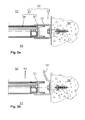
- FIGS. 3a to 3c each show a section of a first embodiment of a mounting element according to the invention 30.
- an end portion 21 of the fixed element 20 is partially received between two side parts 12 of the wall terminal 10.
- the fixed element 20 has a glass pane 26.
- the end portion 21 is formed as a version of the glass sheet 26.
- the end region 21 is formed as a double T-profile 23, wherein a first part 24 of the double T-profile 23 rests against the side parts 12 and a second part 25 of the double T-profile 23, the glass sheet 26 includes.
- the end portion 21 is made of aluminum.
- the wall connection 10 comprises two L-profiles 40, one leg of which in each case forms a side part 12 and whose other leg in each case forms a wall part 11.
- the wall parts 11 are in FIG. 3a completely on the wall 50 at.
- the wall parts 11 have attachment regions 17, which comprise recesses. Through these recesses screws are guided as a fastener 31, which are held by means of a dowel 32 in the wall 50.
- the wall portion 11 serves to secure the terminal 10 to the wall 50.
- the L-profiles have the same orientation, with the legs of the L-profiles 40, which each form the wall portion 11, to the interior 51 show.
- FIG. 3b is the cut of the FIG. 3a shown in a state in which a burglar with the aid of a tool, the side part 12, which faces an outer space 52, has bent.
- the wall connection 10 has a blocking region 14 after the bending over of the side part 12.
- the blocking region 14 protrudes into a recess 22 formed by the first part 24 of the double T-profile 23. Attempts the burglar now according to the arrows 60, lever out the fixed member 20 and to move to the outer space 52, the blocking region 14 holds the end portion 21 positively. This does not make it possible for the burglar to remove the fixed element 20 within a predetermined time, which has improved the burglary protection compared to the prior art.
- the blocking region 14 is formed only during the bending of the side part 12.
- the wall part 11 of the L-profile 40 facing the exterior has the blocking region 14.
- a first area of the wall part 12 still rests against the wall 50 and thus serves as a contact area 13.
- the blocking area 14 corresponds to a second area of the wall part 11 which projects from the wall 50. The second area has been bent with bending of the side part 12 between the mounting portions 17 with.
- the blocking region 14 has a first end 15, which projects into the recess 22.
- a second end 16 of the blocking region 14 adjoins the plant area 13 directly.
- the first end 15 faces the inner space 51, while the second end 16 faces the outer space 52.
- the blocking region 14 extends obliquely and barb-shaped into the receiving space 18.
- the first end 15 is located in a lower, facing the interior 51 quarter of the Receiving space 18.
- the blocking region 14 is formed at the same depth as the attachment region 17 with the attachment elements 31.
- Figure 3c is a plan view of the inner space 51 in the direction of the outer space 52 on the wall portion 11 of the outer space 52 facing L-profile 40 from FIG. 3b shown.
- the interior 51 facing L-profile 40 has been previously removed.
- Figure 3c shows how the wall part 11 is formed along a longitudinal direction 61 of the wall terminal 10 after bending of the side part 12.
- the wall part 11 is formed on the wall 50 in the attachment area 17 around the attachment element 31, so that the attachment area 17 also corresponds at least to a part of the attachment area 13.
- the wall portion 11 abuts against the wall 50 before being bent without being fastened.
- this second region of the wall part can thus be bent over and form the blocking region 14.
- the blocking region 14 is wave-shaped along the longitudinal direction of the wall connection 10, as in FIG Figure 3c shown. Preferably, all wave crests of the blocking region 14 protrude into the recess 22.
- the attachment regions 17 may have a spacing of 30 to 50 cm.
- the L-profiles 40 have a wall thickness of 2-3 mm and are formed of steel. It has been experimentally shown that in this case the wall portion 11 is flexible enough to form a blocking region 14 when bending a side part 12 and yet has sufficient strength to hold the end portion 21 in a removal movement according to the arrow 60 in a form-fitting manner.
- An example of an L-profile 40 and an end region 21, which are matched to one another in order to be able to form a blocking region 14, which projects into the recess 22, has the following dimensions: the end region 21 has a depth 42 of 30 mm, wherein the wall portion 11 has substantially the same depth 43.
- the width 44 of the side part 12 is 30 to 40 mm.
- the distance of the end portion 21 to the contact area 13, which is provided as a game 45 to compensate for building tolerances is 10 to 20 mm.
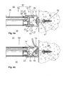
- FIGS. 4a and 4b show a second embodiment of a mounting element according to the invention 30.
- the second embodiment corresponds to the first embodiment of FIGS. 3a to 3c , unless otherwise described below.
- the following will focus on the differences Figure 3a and 3b received.
- the view corresponds to FIG. 4a the view of FIG. 3a and the view of FIG. 4b the view of FIG. 3b
- the two L-profiles 40 are arranged overlapping so that the recesses for performing the fastening elements 31 are arranged one above the other.
- the wall part 11, which forms the blocking region 14, does not rest directly on the wall 50, but on the wall part 11 of the L-profile 40 facing the interior 51.
- FIG. 5a is a section of a third embodiment of a mounting element 30 according to the invention and in FIG. 5b a section of a fourth embodiment of a mounting element according to the invention shown.
- the in the FIGS. 5a and 5b illustrated sectional view corresponds to the sectional view of FIGS. 3a and 4a .
- a blocking region 14 was prefabricated in each case. This means that the blocking region 14 does not first arise when the side part 12 is bent over.
- the blocking area 14 of the third and fourth embodiment also extends obliquely, barbed and arcuate into the receiving space 18 inside.
- the first end 15 lies in a lower to the interior 51 facing quarter of the receiving area 18 and projects into the recess 22nd
- FIG. 5a In contrast to the first and the second embodiment, forming in FIG. 5a the side parts 12 and the wall part 11 a U-profile 41 as a wall connection 10.
- a blocking region 14 was punched out even before the installation of the installation element 30.
- the wall terminal 10 In FIG. 5b the wall terminal 10, however, is formed of two L-profiles 40. In the L-profile 40, which faces the outer space 52, the blocking region 14 has been preformed.
- the blocking area 14 of the FIGS. 5a and 5b also be wavy.
- the blocking region 14 and the attachment region 17 likewise alternate, but the blocking region 14 is not wave-shaped, but is formed parallel to the wall 50.
- cuts in the wall part 11 are provided.
- first and / or the second embodiment may be provided with cuts, so that the blocking region 14 is formed parallel to the wall 50 during bending.
- a wall connection 10 can be equipped with a U-profile 41, in which the blocking region only arises during bending when corresponding cuts are provided in the U-profile 41.
Landscapes
- Engineering & Computer Science (AREA)
- Civil Engineering (AREA)
- Structural Engineering (AREA)
- Mechanical Engineering (AREA)
- Connection Of Plates (AREA)
- Finishing Walls (AREA)
Abstract
Description
- Die Erfindung betrifft ein Einbauelement zur Trennung eines Innenraumes von einem Außenraum mit einem feststehenden Element, welches einen Endbereich aufweist, und mit einem Wandanschluss zur Befestigung des feststehenden Elementes an einer Wand. Der Wandanschluss weist Seitenteile zur Aufnahme des Endbereiches und mindestens ein Wandteil zur Befestigung des Wandanschlusses an der Wand auf gemäß dem Oberbegriff des Anspruchs 1.
- Bekannte Einbauelemente weisen einen Wandanschluss auf, welcher als ein U-Profil ausgebildet ist, wie in
Figur 2a dargestellt. Ein Einbrecher kann das zum Außenraum gewandte Seitenteil umbiegen, wie inFigur 2b dargestellt. Der Einbrecher kann dann das feststehende Element heraushebeln und in Richtung des Außenraumes entfernen. Hierdurch kann sich der Einbrecher innerhalb einer kurzen Zeit Zugang zu dem Innenraum verschaffen. - Es ist die Aufgabe der vorliegenden Erfindung, ein Einbauelement zur Verfügung zu stellen, welches einen verbesserten Einbruchsschutz aufweist.
- Zur Lösung dieser Aufgabe wird ein Einbauelement mit den Merkmalen des Anspruches 1 vorgeschlagen. In den abhängigen Ansprüchen sind bevorzugte Weiterbildungen angegeben.
- Erfindungsgemäß ist vorgesehen, dass der Wandanschluss derart ausgestaltet ist, dass nach einem Umbiegen eines Seitenteiles der Wandanschluss einen Blockierbereich aufweist, der in eine Ausnehmung des Endbereichs hinein ragbar ist.
- Im montierten Zustand des Einbauelementes ist der Endbereich des feststehenden Elementes im Wandanschluss aufgenommen. Nach einem Umbiegen eines Seitenteiles ragt im montierten Zustand der Blockierbereich in die Ausnehmung des Endbereiches hinein. Das heißt, der Blockierbereich greift in die Ausnehmung des Endbereiches ein, ohne den Endbereich berühren zu müssen. Der Endbereich und der Wandanschluss sind somit vor der Montage soweit aufeinander abgestimmt, dass nach der Montage des Einbauelementes und nach Umbiegen des Seitenteiles der Blockierbereich in die Ausnehmung ragt.
- Spätestens während einer Bewegung des feststehenden Elementes in Richtung des Außenraumes gehen der Endbereich und der Blockierbereich einen Formschluss ein. Hierdurch hält der Blockierbereich den Endbereich formschlüssig während einer Bewegung des feststehenden Elementes in Richtung des Außenraumes. Somit wird ein Entfernen des feststehenden Elementes in Richtung des Außenraumes verhindert. Daher kann ein Einbrecher nicht mehr Zutritt zum Innenraum erlangen. Der Einbruchsschutz ist somit verbessert. Insbesondere kann mit der vorliegenden Erfindung ein Einbruchsschutz der Widerstandsklasse RC3 der europäischen Norm EN 1627 erreicht werden. Bei Einhalten der Widerstandsklasse RC3 versucht ein gewohnt vorgehender Täter nicht nur mit einfachen Werkzeugen wie einem Schraubendreher, einer Zange oder einem Keil, sondern zusätzlich mit einem zweiten Schraubendreher und einem Kuhfuß vergeblich, das Einbauelement innerhalb von fünf Minuten aufzubrechen.
- Der Einbrecher versucht vom Außenraum Zutritt zum Innenraum zu erlangen. Die Bezeichnungen Außenraum und Innenraum geben die Richtung vor, in die ein Einbrecher versucht, Zutritt zu erlangen. Die Bezeichnungen Außenraum und Innenraum beinhalten nicht, ob der Außen- und/oder Innenraum überdacht ist. Vielmehr können der Außen- und der Innenraum z. B. beide überdacht sein.
- Das feststehende Element kann ein Türelement oder ein Fensterelement, z. B. ein Oberlicht, sein. Das Einbauelement kann noch mindestens ein weiteres Tür- oder Fensterelement aufweisen. Insbesondere kann das weitere Tür- oder Fensterelement beweglich sein. In einer Ausführungsform ist das feststehende Element Teil einer Schiebetüranordnung. Das Einbauelement kann der Schiebetüranordnung entsprechen. Das bewegliche Türelement ist als Schiebetür ausgebildet und kann im geöffneten Zustand das feststehende Element teilweise überlappen. Es ist denkbar, dass die Schiebetüranordnung manuell oder automatisch durch berührungslose Sensorik geöffnet werden kann.
- Das feststehende Element und/oder gegebenenfalls das bewegliche Türoder Fensterelement kann eine Glasscheibe enthalten. In diesem Fall kann der Endbereich des feststehenden Elementes einer Fassung der Glasscheibe entsprechen.
- Die Seitenteile dienen dazu, den Endbereich zwischen den Seitenteilen zumindest teilweise aufzunehmen. Der Wandanschluss kann zum Ausgleich von Bautoleranzen der Wand dienen. Der Wandanschluss kann insbesondere zur Befestigung des feststehenden Elementes an eine seitliche Wand dienen. Es ist auch denkbar, dass der Wandanschluss zusätzlich oder alternativ zur Befestigung an eine obere und/oder untere Wand dient. Ein erster Bereich des Wandteiles kann als Anlagebereich zum Anliegen an die Wand oder an ein weiteres Wandteil ausgebiidet sein.
- Insbesondere ist nach Umbiegen eines der beiden Seitenteile der Blockierbereich vorhanden, während nach Umbiegen des anderen Seitenteiles kein Blockierbereich vorhanden ist. Das Seitenteil, nach dessen Umbiegen der Wandbereich einen in die Ausnehmung ragbaren Blockierbereich aufweist, ist insbesondere das im montierten Zustand zum Außenraum gewandte Seitenteil.
- Der Wandanschluss muss nicht erst nach einem Umbiegen des Seitenteiles den in die Ausnehmung ragbaren Blockierbereich aufweisen. Von dem Erfindungsgedanken sind auch Einbauelemente erfasst, deren Wandanschluss bereits vor dem Umbiegen einen in die Ausnehmung ragbaren Blockierbereich aufweisen. Erfindungsgemäß muss der in die Ausnehmung ragbare Blockierbereich zumindest nach einem Umbiegen des Seitenteils vorliegen. Das heißt, spätestens, wenn der Einbrecher das Seitenteil umgebogen hat, ist der Blockierbereich vorhanden und blockiert ein Heraushebeln des feststehenden Elementes.
- In einer ersten Alternative liegt der Blockierbereich auch schon vor dem Umbiegen vor. Insbesondere ist der Blockierbereich vorgefertigt, insbesondere vorgestanzt, bereits bei einer Montage des Einbauelementes vorhanden. So kann der Blockierbereich bei einer Fertigung des Einbauelementes gestanzt werden.
- In einer zweiten Alternative entsteht der Blockierbereich während des Umbiegens des Seitenteiles. Das heißt, bei dem Umbiegen des Seitenteiles wird zugleich ein Bereich des Wandanschlusses mitverbogen, der nach dem Umbiegen als Blockierbereich dient.
- Vorzugsweise ist der Blockierbereich als ein monolithischer Bereich des Wandteiles und/oder zumindest eines Seitenteiles ausgebildet.
- Bevorzugt ist ein zweiter Bereich eines Wandteiles als Blockierbereich ausgebildet. Hierbei können insbesondere der Blockierbereich und der Anlagebereich monolithisch ausgebildet sein. Hierdurch kann Material eingespart werden. Ensteht der Blockierbereich erst beim Umbiegen des Seitenteiles, so ist der zweite Bereich umbiegbar ausgestaltet.
- Ein Aufnahmeraum kann im montierten Zustand des Einbauelementes von dem Anlagebereich und den Seitenteilen zur Aufnahme des Endbereiches gebildet sein und der Blockierbereich kann im montierten Zustand in den Aufnahmeraum hineinragen.
- Der Blockierbereich weist ein erstes Ende, das in die Ausnehmung ragbar ist, und ein zweites Ende, das mit dem übrigen Wandanschluss verbunden ist, auf. Insbesondere kann das zweite Ende des Blockierbereiches am Anlagebereich oder in der Nähe des Anlagebereiches angeordnet sein.
- Es ist denkbar, dass sich im montierten Zustand zumindest das erste Ende des Blockierbereiches in der dem Innenraum zugewandten Hälfte des Aufnahmeraumes befindet, insbesondere in dem Innenraum zugewandten Viertel des Aufnahmeraumes. Somit ist das erste Ende von dem Einbrecher weit entfernt.
- Vorzugsweise ist das erste Ende des Blockierbereiches im montierten Zustand des Einbauelementes dem Innenraum zugewandt und das zweites Ende im montierten Zustand des Einbauelementes dem Außenraum zugewandt. Der Blockierbereich kann schräg in den Aufnahmeraum verlaufen. In Richtung des Außenraumes ist der Blockierbereich demnach als Widerhaken ausgebildet. Hierdurch wird dem Einbrecher ein Umfassen des Blockierbereiches erschwert.
- Besonders bevorzugt verläuft der Blockierbereich von dem ersten Ende des Blockierbereiches zu dem zweiten Ende des Blockierbereichs bogenförmig. Das heißt, der Blockierbereich ist in einem senkrecht zu einem Seitenteil und zum Anlagebereich verlaufenen Querschnitt bogenförmig ausgebildet. Hierdurch kann der Blockierbereich besonders gut Kräfte aufnehmen.
- Insbesondere ragt im montierten Zustand der Blockierbereich entlang in Längsrichtung des Wandanschlusses nicht über die ganze Länge in die Ausnehmung hinein. Es genügt, dass der Blockierbereich so ausgebildet ist, dass der Blockierbereich nur an einer Stelle in die Ausnehmung hinein ragbar ist. Bevorzugt ist der Blockierbereich an mehreren Stellen in die Ausnehmung hinein ragbar. Besonders bevorzugt sind die mehreren Stellen über die gesamte Länge des Wandanschlusses verteilt. Hierdurch ist dem Einbrecher ein Herausnehmen des feststehenden Elementes besonders erschwert. Der Blockierbereich kann in Längsrichtung unterbrochen sein.
- In einer Ausführungsform der Erfindung ist der Blockierbereich in Längsrichtung des Wandanschlusses wellenförmig ausgebildet. Hierbei ist mindestens ein Wellenkamm des Blockierbereiches in die Ausnehmung hinein ragbar ausgebildet. Bevorzugt ragen mehrere Wellenkämme und besonders bevorzugt ragen alle Wellenkämme in die Ausnehmung. Der wellenförmige Blockierbereich kann durch einfaches Biegen entstehen und ist daher besonders einfach herstellbar. Insbesondere kann der Blockierbereich wellenförmig ausgebildet sein, wenn bei einem Umbiegen des Seitenteils erst der Blockierbereich entsteht.
- In einer alternativen Ausführungsform ist der Blockierbereich in Längsrichtung des Wandanschlusses parallel zum Anlagebereich ausgebildet. Hierdurch ragt in Längsrichtung des Wandanschlusses ein besonders großer Teil des Blockierbereichs in die Ausnehmung.
- Insbesondere ist der Blockierbereich in Längsrichtung des Wandanschlusses von mindestens einem Befestigungsbereich unterbrochen. Hierbei ist der Befestigungsbereich der Teil des Anlagebereiches, der die Befestigung des Wandanschlusses an der Wand ermöglicht. So kann beispielsweise der Befestigungsbereich eine Aussparung zum Durchführen von einem Befestigungselement umfassen. Das Befestigungselement kann beispielsweise eine Schraube sein, die durch die Aussparung hindurch in einem Dübel in der Wand gehalten ist. Insbesondere weisen die Befestigungsbereiche einen Abstand von 30 bis 50 cm auf. Der Blockierbereich kann zumindest teilweise auf derselben Tiefe wie der mindestens eine Befestigungsbereich angeordnet sein. Das heißt, dass sich der Blockierbereich und der Befestigungsbereich entlang der Längsrichtung des Wandanschlusses abwechseln. Hierdurch kann auch bei einer geringen Tiefe des Wandanschlusses der Blockierbereich verwirklicht werden.
- Der Blockierbereich kann dieselbe Wandstärke wie das Wandteil und/oder das Seitenteil aufweisen. Durch die Materialauswahl und/oder die Wandstärke können die Seitenteile umbiegbar ausgestaltet sein. Durch die Materialauswahl und/oder die Wandstärke kann der Blockierbereich genügend Festigkeit aufweisen, um das feststehende Element zu halten. Durch eine geringe Wandstärke kann der Blockierbereich beim Umbiegen der Seitenteile entstehen. Der Blockierbereich, das Wandteil und/oder die Seitenteile können aus Stahl, insbesondere nicht rostenden Stahl, ausgebildet sein. Der Blockierbereich, das Wandteil und/oder das Seitenteil können eine Wandstärke von 2 bis 3 mm aufweisen. Ein Vorteil der Erfindung liegt darin, dass die Wandstärke der Seitenteile nicht derart hoch sein muss, dass ein Einbrecher das Seitenteil nicht mehr aufstemmen kann.
- Bevorzugt sind zumindest ein Wandteil und ein Seitenteil monolithisch ausgebildet. Es ist denkbar, dass der Wandanschluss zwei L-Profile umfasst. Jeweils ein Schenkel eines L-Profils bildet ein Seitenteil und jeweils ein Schenkel eines L-Profils bildet ein Wandteil. Hierdurch können einfache Formteile verwendet werden.
- Die Schenkel beider L-Profile, welche das Wandteil bilden, können einander zugekehrt, insbesondere überlappend, anordbar sein. Insbesondere die Aussparungen der beiden Wandteile können hierbei überlappen, so dass jeweils ein Befestigungselement durch je eine Aussparung beider Wandteile führbar ist. Das Wandteil des L-Profils, welches auch das zum Außenraum gerichtete Seitenteil umfasst, ist bevorzugt über dem Wandteil des L-Profils, welches das zum Innenraum gerichtete Seitenteil umfasst, angeordnet.
- Alternativ kann vorgesehen sein, dass die L-Profile dieselbe Ausrichtung haben wie ein Schenkel eines L-Profils, das ein Wandteil bildet, welches in den Innenraum zeigt. Diese Anordnung ist besonders montagefreundlich.
- Der Wandanschluss kann alternativ ein U-Profil umfassen, wobei die Seitenteile und das Wandteil das U-Profil bilden. Das U-Profil kann insbesondere vorgesehen sein, wenn der Blockierbereich vorgefertigt ist. Alternativ kann in dem U-Profil mindestens ein Schlitz, bevorzugt mehrere Schlitze vorgesehen sein, die den zweiten Bereich des Wandteils des U-Profils bei einer Biegung eines Seitenteils umbiegbar gestalten.
- Der Endbereich kann aus Aluminium gefertigt sein. Der Teil des Endbereiches, der die Ausnehmung umgibt, kann U-Profil-artig ausgestaltet sein, wobei jeweils ein Schenkel des U-Profil-artigen Teils zur inneren Anlage an die Seitenteile ausgebildet ist. Ist der Endbereich als Fassung ausgebildet, kann der Endbereich insbesondere als doppeltes T-Profil ausgebildet sein, wobei ein erstes Teil des doppelten T-Profils zur Anlage an die Seitenteile und ein zweiter Teil des doppelten T-Profils zur Aufnahme der Glasscheibe dienen.
- Bei der Abstimmung des Endbereichs und des Wandanschlusses können eine oder mehrere der folgenden Maße vorgesehen sein: Der Endbereich weist eine Tiefe von 30 mm auf. Die Tiefe des Wandteils entspricht zumindest im Wesentlichen der Tiefe des Endbereiches. Die Breite des Seitenteils beträgt 30 bis 40 mm. Der Abstand des Endbereiches zum Anlagebereich, der als Spiel zum Ausgleich von Bautoleranzen vorgesehen ist, kann teilweise 10 bis 20 mm betragen.
- Weitere Vorteile, Merkmale und Einzelheiten der Erfindung ergeben sich aus der nachfolgenden Beschreibung, in der unter Bezugnahme auf die Zeichnungen mehrere Ausführungsbeispiele der Erfindung im Einzelnen beschrieben sind. Dabei können die in den Ansprüchen und in der Beschreibung erwähnten Merkmale jeweils einzeln für sich oder in beliebiger Kombination erfindungswesentlich sein.
- Es zeigen:
- Fig. 1a
- eine erste Variante eines erfindungsgemäßen Einbauelementes,
- Fig. 1b
- eine zweite Variante eines erfindungsgemäßen Einbauelementes,
- Fig. 2a
- einen Schnitt durch ein Einbauelement gemäß dem Stand der Technik,
- Fig. 2b
- den Schnitt aus
Figur 2a , wobei ein Seitenteil umgebogen ist, - Fig. 3a
- einen Schnitt durch ein erstes Ausführungsbeispiel eines erfindungsgemäßen Einbauelementes entlang der Linie I-I aus
Figur 1a oder Figur 1b , - Fig. 3b
- den Schnitt aus
Figur 3a mit einem umgebogenen Seitenteil, - Fig. 3c
- eine Draufsicht auf einen Ausschnitt des ersten Ausführungsbeispieles des erfindungsgemäßen Einbauelementes bei umgebogenem Seitenteil,
- Fig. 4a
- einen Schnitt durch ein zweites Ausführungsbeispiel eines erfindungsgemäßen Einbauelementes entlang der Linie I-I aus
Figur 1a oder Figur 1b , - Fig. 4b
- den Schnitt aus
Figur 4a mit umgebogenem Seitenteil, - Fig. 5a
- einen Schnitt durch ein drittes Ausführungsbeispiel eines erfindungsgemäßen Einbauelementes entlang der Linie I-I aus
Figur 1a oder Figur 1b , - Fig. 5b
- einen Schnitt durch ein viertes Ausführungsbeispiel eines erfindungsgemäßen Einbauelementes entlang der Linie I-I aus
Figur 1a oder Figur 1b . - Elemente mit gleicher Funktion und Wirkungsweise sind in den
Figuren 1 a bis 5b mit denselben Bezugszeichen versehen. - In
Figur 1 a ist eine erste Variante eines erfindungsgemäßen Einbauelementes 30 dargestellt. Das Einbauelement 30 weist ein feststehendes Element 20, welches einem Fensterelement mit einer Glasscheibe 26 entspricht, auf. Das feststehende Element 20 ist auf allen vier Seiten von einem Wandanschluss 10 umgeben, durch den das feststehende Element 20 an einer Wand 50 befestigt ist. - In
Figur 1b ist eine zweite Variante eines erfindungsgemäßen Einbauelementes 30 dargestellt. Das Einbauelement 30 ist als Schiebetüranordnung ausgebildet. Das Einbauelement 30 weist zwei feststehende Elemente 20 auf, welche zwei bewegliche Elemente 32 umgeben, die als Schiebetüren ausgebildet sind. Die feststehenden Elemente 20 und die beweglichen Elemente 32 weisen eine Glasscheibe 26 auf. Das Einbauelement 30 weist jeweils einen Wandanschluss 10 für je ein feststehendes Element 20 auf, wobei der Wandanschluss 10 das jeweilige feststehende Element 20 an einer seitlichen Wand 50 befestigt. -
Figur 2a und 2b zeigen einen Ausschnitt aus einem Schnitt durch ein Einbauelement gemäß dem Stand der Technik, wobeiFigur 2b denselben Ausschnitt wieFigur 2a , jedoch mit einem umgebogenen Seitenteil 12, zeigt.Figur 2a und 2b zeigen einen Schnitt entlang einer Linie, die der Linie I-I, welche in denFigur 1 a und 1 b für ein erfindungsgemäßes Einbauelement dargestellt ist, gleicht. InFigur 2a ist ein Endbereich 21 eines feststehenden Elementes 20 in einem Wandanschluss 10 aufgenommen. Ein Einbrecher kann zwischen dem Endbereich 21 und einem Seitenteil 12 des Wandanschlusses 10 ein Werkzeug ansetzen, sodass ein Seitenteil 12 umgebogen wird, wie inFigur 2b dargestellt. Der Einbrecher kann nun das feststehende Element 20 gemäß dem Pfeil 60 heraushebeln und so Zugang zu einem Innenraum 51 erlangen. -
Figur 3a bis 3c zeigen jeweils einen Ausschnitt aus einem ersten Ausführungsbeispiel eines erfindungsgemäßen Einbauelementes 30. Hierbei ist ein Schnitt entlang der Linie I-I ausFigur 1 a oder 1 b in denFiguren 3a und 3b dargestellt. InFigur 3a ist ein Endbereich 21 des feststehenden Elementes 20 teilweise zwischen zwei Seitenteilen 12 des Wandanschlusses 10 aufgenommen. Das feststehende Element 20 weist eine Glasscheibe 26 auf. Der Endbereich 21 ist als Fassung der Glasscheibe 26 ausgebildet. Der Endbereich 21 ist als doppeltes T-Profil 23 ausgebildet, wobei ein erster Teil 24 des doppelten T-Profils 23 an den Seitenteilen 12 anliegt und ein zweiter Teil 25 des doppelten T-Profils 23 die Glasscheibe 26 umfasst. Der Endbereich 21 ist aus Aluminium gefertigt. - Der Wandanschluss 10 umfasst zwei L-Profile 40, deren ein Schenkel jeweils ein Seitenteil 12 bildet und deren anderer Schenkel jeweils ein Wandteil 11 bildet. Die Wandteile 11 liegen in
Figur 3a vollständig an der Wand 50 an. Die Wandteile 11 weisen Befestigungsbereiche 17 auf, welche Aussparungen umfassen. Durch diese Aussparungen sind Schrauben als Befestigungselement 31 geführt, welche mithilfe eines Dübels 32 in der Wand 50 gehalten werden. Somit dient das Wandteil 11 zur Befestigung des Anschlusses 10 an der Wand 50. InFigur 3a haben die L-Profile dieselbe Ausrichtung, wobei die Schenkel der L-Profile 40, die jeweils das Wandteil 11 bilden, zum Innenraum 51 zeigen. - In
Figur 3b ist der Schnitt derFigur 3a in einem Zustand gezeigt, bei der ein Einbrecher mithilfe eines Werkzeuges das Seitenteil 12, welches zu einem Außenraum 52 zugewandt ist, umgebogen hat. Erfindungsgemäß weist der Wandanschluss 10 nach dem Umbiegen des Seitenteils 12 einen Blockierbereich 14 auf. Der Blockierbereich 14 ragt in eine Ausnehmung 22, die durch den ersten Teil 24 des doppelten T-Profils 23 gebildet ist, hinein. Versucht der Einbrecher nun gemäß den Pfeilen 60, das feststehende Element 20 herauszuhebeln und zum Außenraum 52 zu bewegen, so hält der Blockierbereich 14 den Endbereich 21 formschlüssig fest. Hierdurch gelingt es dem Einbrecher nicht, das feststehende Element 20 innerhalb einer vorgegebenen Zeit herauszunehmen, wodurch sich der Einbruchschutz im Vergleich zum Stand der Technik verbessert hat. - In dem Ausführungsbeispiel der
Figuren 3a bis 3c ist der Blockierbereich 14 erst während des Umbiegens des Seitenteiles 12 entstanden. Das Wandteil 11 des zum Außenraum gewandten L-Profils 40 weist den Blockierbereich 14 auf. Ein erster Bereich des Wandteiles 12 liegt immer noch an der Wand 50 an und dient somit als Anlagebereich 13. Der Blockierbereich 14 entspricht einem zweiten Bereich des Wandteiles 11, welches von der Wand 50 absteht. Der zweite Bereich ist bei Umbiegen des Seitenteils 12 zwischen den Befestigungsbereichen 17 mit umgebogen worden. - Der Blockierbereich 14 weist ein erstes Ende 15 auf, welches in die Ausnehmung 22 hineinragt. Ein zweites Ende 16 des Blockierbereiches 14 schließt sich unmittelbar an den Anlagenbereich 13 an. Das erste Ende 15 ist dem Innenraum 51 zugewandt, während das zweite Ende 16 dem Außenraum 52 zugewandt ist. Somit verläuft der Blockierbereich 14 schräg und widerhakenförmig in den Aufnahmeraum 18 hinein. Das erste Ende 15 liegt dabei in einem unteren, zum Innenraum 51 gewandten Viertel des Aufnahmeraumes 18. Zudem ist der Blockierbereich 14, wie in
Figur 3b dargestellt, leicht bogenförmig ausgebildet. Der Blockierbereich 14 ist auf derselben Tiefe wie der Befestigungsbereich 17 mit den Befestigungselementen 31 ausgebildet. - In
Figur 3c ist eine Draufsicht von dem Innenraum 51 in Richtung des Außenraumes 52 auf das Wandteil 11 des zum Außenraum 52 gewandten L-Profils 40 ausFigur 3b dargestellt. Das zum Innenraum 51 gewandte L-Profil 40 wurde zuvor entfernt.Figur 3c zeigt, wie das Wandteil 11 entlang einer Längsrichtung 61 des Wandanschlusses 10 nach Umbiegen des Seitenteiles 12 ausgebildet ist. Das Wandteil 11 ist im Befestigungsbereich 17 um das Befestigungselement 31 herum an der Wand 50 liegend ausgebildet, sodass der Befestigungsbereich 17 zugleich zumindest einem Teil des Anlagebereichs 13 entspricht. Zwischen den Befestigungsbereichen 17 liegt das Wandteil 11 vor dem Umbiegen an der Wand 50 an, ohne befestigt zu sein. Während des Umbiegens des Seitenteiles 11 kann somit dieser zweite Bereich des Wandteiles umgebogen werden und den Blockierbereich 14 bilden. Der Blockierbereich 14 ist entlang der Längsrichtung des Wandanschlusses 10 wellenförmig ausgebildet, wie inFigur 3c dargestellt. Bevorzugt ragen alle Wellenkämme des Blockierbereiches 14 in die Ausnehmung 22 hinein. - Die Befestigungsbereiche 17 können einen Abstand von 30 bis 50 cm aufweisen. Die L-Profile 40 weisen eine Wandstärke von 2-3 mm auf und sind aus Stahl ausgebildet. Es hat sich experimentell gezeigt, dass hierbei das Wandteil 11 biegsam genug ist, um einen Blockierbereich 14 beim Umbiegen eines Seitenteiles 12 auszubilden und dennoch genügend Festigkeit aufweist, um den Endbereich 21 bei einer Herausnahmebewegung gemäß dem Pfeil 60 formschlüssig zu halten.
- Ein Beispiel eines L-Profils 40 und eines Endbereiches 21 , welche aufeinander abgestimmt sind, um ein Blockierbereich 14, der in die Ausnehmung 22 hineinragt, bilden zu können, weist folgende Maße auf: der Endbereich 21 weist eine Tiefe 42 von 30 mm auf, wobei das Wandteil 11 im Wesentlichen dieselbe Tiefe 43 aufweist. Die Breite 44 des Seitenteiles 12 beträgt 30 bis 40 mm. Der Abstand des Endbereiches 21 zum Anlagebereich 13, der als Spiel 45 zum Ausgleich von Bautoleranzen vorgesehen ist, beträgt 10 bis 20 mm.
- Die
Figuren 4a und 4b zeigen ein zweites Ausführungsbeispiel eines erfindungsgemäßen Einbauelementes 30. Das zweite Ausführungsbeispiel entspricht dem ersten Ausführungsbeispiel derFiguren 3a bis 3c , soweit im Folgenden nicht abweichend beschrieben. Im Folgenden wird auf die Unterschiede zuFigur 3a und 3b eingegangen. Insbesondere entspricht die Ansicht derFigur 4a der Ansicht derFigur 3a und die Ansicht derFigur 4b der Ansicht derFigur 3b . Im Gegensatz zu dem ersten Ausführungsbeispiel derFiguren 3a bis 3c sind die beiden L-Profile 40 derart überlappend angeordnet, dass die Aussparungen zum Durchführen der Befestigungselemente 31 übereinander angeordnet sind. Das Wandteil 11, das den Blockierbereich 14 bildet, liegt nicht direkt an der Wand 50, sondern an dem Wandteil 11 des zum Innenraum 51 gewandten L-Profils 40 an. - In
Figur 5a ist ein Ausschnitt aus einem dritten Ausführungsbeispiel eines erfindungsgemäßen Einbauelementes 30 und inFigur 5b ein Ausschnitt aus einem vierten Ausführungsbeispiel eines erfindungsgemäßen Einbauelementes dargestellt. Die in denFiguren 5a und 5b dargestellte Schnittansicht entspricht der Schnittansicht derFiguren 3a und4a . In dem dritten und vierten Ausführungsbeispiel wurde jeweils ein Blockierbereich 14 vorgefertigt. Das heißt, dass der Blockierbereich 14 nicht erst beim Umbiegen des Seitenteiles 12 entsteht. Der Blockierbereich 14 des dritten und vierten Ausführungsbeispiels verläuft ebenfalls schräg, widerhakenund bogenförmig in den Aufnahmeraum 18 hinein. Das erste Ende 15 liegt dabei in einem unteren zum Innenraum 51 gewandten Viertel des Aufnahmebereiches 18 und ragt in die Ausnehmung 22. - Im Gegensatz zu dem ersten und dem zweiten Ausführungsbeispiel, bilden in
Figur 5a die Seitenteile 12 und das Wandteil 11 ein U-Profil 41 als Wandanschluss 10. In dem U-Profil 41 wurde bereits vor der Montage des Einbauelementes 30 ein Blockierbereich 14 ausgestanzt. InFigur 5b ist der Wandanschluss 10 hingegen aus zwei L-Profilen 40 gebildet. In das L-Profil 40, das dem Außenraum 52 zugewandet ist, wurde der Blockierbereich 14 vorgeformt. - In einer Draufsicht, welche die Draufsicht der
Figur 3c entspricht, könnte der Blockierbereich 14 derFiguren 5a und 5b ebenfalls wellenförmig ausgebildet sein. Alternativ wechseln sich zwar ebenfalls der Blockierbereich 14 und der Befestigungsbereich 17 ab, jedoch ist der Blockierbereich 14 nicht wellenförmig, sondern parallel zur Wand 50 ausgebildet. Hierzu sind Schnitte im Wandteil 11 vorgesehen. - In nicht dargestellten Alternativen können auch das erste und/oder das zweite Ausführungsbeispiel mit Schnitten vorgesehen sein, so dass der Blockierbereich 14 beim Umbiegen parallel zur Wand 50 entsteht. Ebenfalls kann ein Wandanschluss 10 mit einem U-Profil 41 ausgestattet sein, bei dem der Blockierbereich erst beim Umbiegen entsteht, wenn entsprechende Schnitte im U-Profil 41 vorgesehen sind.
-
- 10
- Wandanschluss
- 11
- Wandteil
- 12
- Seitenteil
- 13
- Anlagebereich
- 14
- Blockierbereich
- 15
- erstes Ende des Blockierbereiches
- 16
- zweites Ende des Blockierbereiches
- 17
- Befestigungsbereich
- 18
- Aufnahmeraum
- 20
- feststehendes Element
- 21
- Endbereich
- 22
- Ausnehmung
- 23
- doppeltes T-Profil
- 24
- erster Teil von 23
- 25
- zweiter Teil von 23
- 26
- Glasscheibe
- 30
- Einbauelement
- 31
- Befestigungselement
- 32
- Dübel
- 40
- L-Profil
- 41
- U-Profil
- 42
- Tiefe des Endbereichs
- 43
- Tiefe des Wandteils
- 44
- Breite des Seitenteils
- 45
- Spiel
- 50
- Wand
- 51
- Innenraum
- 52
- Außenraum
- 60
- Pfeilrichtung
- 61
- Längsrichtung
Claims (15)
- Einbauelement (30) zur Trennung eines Innenraums (51) von einem Außenraum (52) mit einem feststehenden Element (20), das einen Endbereich (21) aufweist, und mit einem Wandanschluss (10) zur Befestigung des feststehenden Elements (20) an einer Wand (50), wobei der Wandanschluss (10) Seitenteile (12) zur Aufnahme des Endbereichs (21) und mindestens ein Wandteil (11) zur Befestigung des Wandanschlusses (10) an der Wand (50) aufweist, dadurch gekennzeichnet, dass der Wandanschluss (10) derart ausgestaltet ist, dass nach einem Umbiegen eines Seitenteils (12) der Wandanschluss (10) einen Blockierbereich (14) aufweist, der in eine Ausnehmung (22) des Endbereichs (21) hinein ragbar ist.
- Einbauelement (30) nach Anspruch 1, dadurch gekennzeichnet, dass ein erster Bereich des Wandteils (11) als Anlagebereich (13) zum Anliegen an die Wand (50) oder ein weiteres Wandteil (11) ausgebildet ist und ein zweiter Bereich eines Wandteils (11) als Blockierbereich (14) ausgebildet ist.
- Einbauelement (30) nach Anspruch 1 oder 2, dadurch gekennzeichnet, dass ein erstes Ende (15) des Blockierbereichs (14), das in die Ausnehmung (22) ragt, dem Innenraum (51) zugewandt ist und ein zweites Ende (16) des Blockierbereichs (14) dem Außenraum (52) zugewandt ist, insbesondere dass der Blockierbereich (14) von dem ersten Ende (15) zu dem zweiten Ende (16) bogenförmig verläuft.
- Einbauelement (30) nach einem der vorhergehenden Ansprüche, dadurch gekennzeichnet, dass der Blockierbereich (14) in Längsrichtung des Wandanschlusses (10) wellenförmig ausgebildet ist.
- Einbauelement (30) nach einem der vorhergehenden Ansprüche, dadurch gekennzeichnet, dass der Blockierbereich (14) in Längsrichtung des Wandanschlusses (10) parallel zum Anlagebereich (13) ausgebildet ist.
- Einbauelement (30) nach einem der vorhergehenden Ansprüche, dadurch gekennzeichnet, dass der Blockierbereich (14) in Längsrichtung des Wandanschlusses (10) von mindestens einem Befestigungsbereich (17) unterbrochen ist, wobei insbesondere der Befestigungsbereich (17) eine Aussparung (17) zum Durchführen von einem Befestigungselement (31) umfasst.
- Einbauelement (30) nach einem der vorhergehenden Ansprüche, dadurch gekennzeichnet, dass der Blockierbereich (14), das Wandteil (11) und/oder das Seitenteil (12) eine Wandstärke von 2 bis 3 mm aufweisen.
- Einbauelement (30) nach einem der vorhergehenden Ansprüche, dadurch gekennzeichnet, dass der Blockierbereich (14), das Wandteil (11) und/oder die Seitenteile (12) aus Stahl, insbesondere nichtrostenden Stahl, ausgebildet sind.
- Einbauelement (30) nach einem der vorhergehenden Ansprüche, dadurch gekennzeichnet, dass der Wandanschluss (10) zwei L-Profile (40) umfasst, wobei jeweils ein Schenkel eines L-Profils (40) ein Seitenteil (12) und jeweils ein Schenkel eines L-Profils (40) ein Wandteil (11) bildet.
- Einbauelement (30) nach Anspruch 9, dadurch gekennzeichnet, dass die Schenkel beider L-Profile (40), die das Wandteil (11) bilden, einander zugekehrt, insbesondere überlappend, anordbar sind.
- Einbauelement (30) nach Anspruch 9, dadurch gekennzeichnet, dass vorgesehen ist, dass die L-Profile (40) dieselbe Ausrichtung haben und ein Schenkel eines L-Profils (40), das ein Wandteil (11) bildet, in den Innenraum (51) zeigt.
- Einbauelement (30) nach einem der vorhergehenden Ansprüche, dadurch gekennzeichnet, dass während des Umbiegens des Seitenteils (12) der Blockierbereich (14) entsteht.
- Einbauelement (30) nach einem der vorhergehenden Ansprüche, dadurch gekennzeichnet, dass der Blockierbereich (14) vorgefertigt, insbesondere vorgestanzt, bereits bei einer Montage des Einbauelements (30) vorhanden ist.
- Einbauelement (30) nach einem der vorhergehenden Ansprüche, dadurch gekennzeichnet, dass der Wandanschluss (10) ein U-Profil (41), insbesondere mit einem vorgefertigten Blockierbereich (14) umfasst, wobei die Seitenteile (12) und das Wandteil (11) das U-Profil (41) bilden.
- Einbauelement (30) nach einem der vorhergehenden Ansprüche, dadurch gekennzeichnet, dass ein Teil (24) des Endbereichs (21), der die Ausnehmung (22) umgibt, U-Profil-artig ausgestaltet ist, wobei jeweils ein Schenkel des U-Profil-artigen Teils (24) zur inneren Anlage an die Seitenteile (12) ausgebildet ist.
Applications Claiming Priority (1)
| Application Number | Priority Date | Filing Date | Title |
|---|---|---|---|
| DE102013107008.6A DE102013107008A1 (de) | 2013-07-03 | 2013-07-03 | Einbauelement |
Publications (2)
| Publication Number | Publication Date |
|---|---|
| EP2821581A1 true EP2821581A1 (de) | 2015-01-07 |
| EP2821581B1 EP2821581B1 (de) | 2017-11-22 |
Family
ID=50846740
Family Applications (1)
| Application Number | Title | Priority Date | Filing Date |
|---|---|---|---|
| EP14001841.7A Active EP2821581B1 (de) | 2013-07-03 | 2014-05-27 | Einbauelement |
Country Status (2)
| Country | Link |
|---|---|
| EP (1) | EP2821581B1 (de) |
| DE (1) | DE102013107008A1 (de) |
Cited By (3)
| Publication number | Priority date | Publication date | Assignee | Title |
|---|---|---|---|---|
| EP3674507A1 (de) | 2018-12-26 | 2020-07-01 | dormakaba Deutschland GmbH | Einbauelement, türanlage mit einbauelement und verfahren zur montage eines einbauelements |
| EP3674508A1 (de) | 2018-12-26 | 2020-07-01 | dormakaba Deutschland GmbH | Einbauelement, türanlage mit einbauelement und verfahren zur montage eines einbauelements |
| CN115354942A (zh) * | 2022-08-19 | 2022-11-18 | 深圳市瑞玮工程有限公司 | 一种新型拼接铝合金窗及其安装方法 |
Families Citing this family (1)
| Publication number | Priority date | Publication date | Assignee | Title |
|---|---|---|---|---|
| CN116752771B (zh) * | 2023-06-15 | 2025-11-14 | 中亿丰建设集团股份有限公司 | 一种建筑装饰幕墙的安装方法及其装置 |
Citations (3)
| Publication number | Priority date | Publication date | Assignee | Title |
|---|---|---|---|---|
| FR95579E (fr) * | 1965-12-10 | 1971-03-26 | Transglas Ag | Encadrement pour éléments de cloisons. |
| US20040003553A1 (en) * | 2002-07-03 | 2004-01-08 | James Donoghue | Vertical glazing frame system for building curtain walls with u-channel glass |
| EP2278109A2 (de) * | 2009-07-24 | 2011-01-26 | Norsk Hydro ASA | Öffnungselement eines Verschlussrahmens, das Mittel gegen das Herausrutschen des Ausfachungselements enthält |
-
2013
- 2013-07-03 DE DE102013107008.6A patent/DE102013107008A1/de not_active Ceased
-
2014
- 2014-05-27 EP EP14001841.7A patent/EP2821581B1/de active Active
Patent Citations (3)
| Publication number | Priority date | Publication date | Assignee | Title |
|---|---|---|---|---|
| FR95579E (fr) * | 1965-12-10 | 1971-03-26 | Transglas Ag | Encadrement pour éléments de cloisons. |
| US20040003553A1 (en) * | 2002-07-03 | 2004-01-08 | James Donoghue | Vertical glazing frame system for building curtain walls with u-channel glass |
| EP2278109A2 (de) * | 2009-07-24 | 2011-01-26 | Norsk Hydro ASA | Öffnungselement eines Verschlussrahmens, das Mittel gegen das Herausrutschen des Ausfachungselements enthält |
Cited By (5)
| Publication number | Priority date | Publication date | Assignee | Title |
|---|---|---|---|---|
| EP3674507A1 (de) | 2018-12-26 | 2020-07-01 | dormakaba Deutschland GmbH | Einbauelement, türanlage mit einbauelement und verfahren zur montage eines einbauelements |
| EP3674508A1 (de) | 2018-12-26 | 2020-07-01 | dormakaba Deutschland GmbH | Einbauelement, türanlage mit einbauelement und verfahren zur montage eines einbauelements |
| DE102018133596A1 (de) | 2018-12-26 | 2020-07-02 | Dormakaba Deutschland Gmbh | Einbauelement, Türanlage mit Einbauelement und Verfahren zur Montage eines Einbauelements |
| DE102018133597A1 (de) | 2018-12-26 | 2020-07-02 | Dormakaba Deutschland Gmbh | Einbauelement, Türanlage mit Einbauelement und Verfahren zur Montage eines Einbauelements |
| CN115354942A (zh) * | 2022-08-19 | 2022-11-18 | 深圳市瑞玮工程有限公司 | 一种新型拼接铝合金窗及其安装方法 |
Also Published As
| Publication number | Publication date |
|---|---|
| DE102013107008A1 (de) | 2015-01-08 |
| EP2821581B1 (de) | 2017-11-22 |
Similar Documents
| Publication | Publication Date | Title |
|---|---|---|
| DE202010012019U1 (de) | Käfigmutter | |
| EP1826507A2 (de) | Befestigungsvorrichtung für die Befestigung von Solarpaneelen an einer Montageschiene | |
| DE102014213468A1 (de) | Leuchte, Anordnung für eine Rasterdecke, Verfahren zum Montieren einer Leuchte, Verfahren zum Demontieren einer Leuchte, sowie Demontagewerkzeug | |
| EP2246577B1 (de) | Befestigungselement | |
| EP2821581B1 (de) | Einbauelement | |
| EP2669534A2 (de) | Montageanordnung | |
| EP3241954B1 (de) | Abhänger für deckenkonstruktionen | |
| EP2444562B1 (de) | Sicherheitsraum | |
| WO2000068581A1 (de) | Befestigungselement zum befestigen von isolationsbahnen oder-platten auf einem festen unterbau | |
| DE202014006758U1 (de) | Verbindungslasche | |
| EP2754805A2 (de) | Riegelstange für einen Riegelstangenbeschlag | |
| DE102017118478A1 (de) | Verrastung einer Dachantenne eines Fahrzeuges mittels eines Drehkreuzes | |
| EP2058463B1 (de) | Eckumlenkung für ein Treibstangenbeschlagsystem für einen Fenster- oder Türflügel | |
| DE102005059383A1 (de) | Vorrichtung zum Ausgleich von Längendifferenzen zwischen einem Zylinderschloss und einem Türblatt | |
| DE102007008667B4 (de) | Befestigungsvorrichtung für ein Aufsatzelement | |
| DE202016102338U1 (de) | Abhänger für Deckenkonstruktionen | |
| EP0447936A2 (de) | Vorrichtung zur Befestigung von Installationselementen | |
| EP1504216B1 (de) | Leuchtenraster mit doppelwandigen seitenreflektoren | |
| EP0778378A1 (de) | Vorrichtung zur Sicherung von Dachdurchbrüchen und Verfahren zur Herstellung der Sicherungsvorrichtung | |
| EP1469137A1 (de) | Firsthaube und Firstabdeckung hieraus | |
| AT523980B1 (de) | IR-Heizpaneel | |
| EP3489449B1 (de) | Objektschutzgitter zum nachträglichen einbau in wandöffnungen | |
| DE102009054644A1 (de) | Beschlagteilanordnung für ein Fenster, eine Tür, eine Klappe oder dergleichen und Verfahren zum Montieren einer Bechlagteilschiene eines Fenster-, Tür- oder Klappenbeschlages bzw. dergleichen | |
| DE60001800T2 (de) | Endverschlusskappe für Rolladenkasten | |
| EP3263788A1 (de) | Verbindung zweier holzbalken |
Legal Events
| Date | Code | Title | Description |
|---|---|---|---|
| PUAI | Public reference made under article 153(3) epc to a published international application that has entered the european phase |
Free format text: ORIGINAL CODE: 0009012 |
|
| 17P | Request for examination filed |
Effective date: 20140527 |
|
| AK | Designated contracting states |
Kind code of ref document: A1 Designated state(s): AL AT BE BG CH CY CZ DE DK EE ES FI FR GB GR HR HU IE IS IT LI LT LU LV MC MK MT NL NO PL PT RO RS SE SI SK SM TR |
|
| AX | Request for extension of the european patent |
Extension state: BA ME |
|
| R17P | Request for examination filed (corrected) |
Effective date: 20150619 |
|
| RBV | Designated contracting states (corrected) |
Designated state(s): AL AT BE BG CH CY CZ DE DK EE ES FI FR GB GR HR HU IE IS IT LI LT LU LV MC MK MT NL NO PL PT RO RS SE SI SK SM TR |
|
| STAA | Information on the status of an ep patent application or granted ep patent |
Free format text: STATUS: EXAMINATION IS IN PROGRESS |
|
| 17Q | First examination report despatched |
Effective date: 20161123 |
|
| RAP1 | Party data changed (applicant data changed or rights of an application transferred) |
Owner name: DORMAKABA DEUTSCHLAND GMBH |
|
| GRAP | Despatch of communication of intention to grant a patent |
Free format text: ORIGINAL CODE: EPIDOSNIGR1 |
|
| STAA | Information on the status of an ep patent application or granted ep patent |
Free format text: STATUS: GRANT OF PATENT IS INTENDED |
|
| INTG | Intention to grant announced |
Effective date: 20170609 |
|
| GRAS | Grant fee paid |
Free format text: ORIGINAL CODE: EPIDOSNIGR3 |
|
| GRAA | (expected) grant |
Free format text: ORIGINAL CODE: 0009210 |
|
| STAA | Information on the status of an ep patent application or granted ep patent |
Free format text: STATUS: THE PATENT HAS BEEN GRANTED |
|
| AK | Designated contracting states |
Kind code of ref document: B1 Designated state(s): AL AT BE BG CH CY CZ DE DK EE ES FI FR GB GR HR HU IE IS IT LI LT LU LV MC MK MT NL NO PL PT RO RS SE SI SK SM TR |
|
| REG | Reference to a national code |
Ref country code: GB Ref legal event code: FG4D Free format text: NOT ENGLISH |
|
| REG | Reference to a national code |
Ref country code: CH Ref legal event code: EP |
|
| REG | Reference to a national code |
Ref country code: IE Ref legal event code: FG4D Free format text: LANGUAGE OF EP DOCUMENT: GERMAN |
|
| REG | Reference to a national code |
Ref country code: AT Ref legal event code: REF Ref document number: 948578 Country of ref document: AT Kind code of ref document: T Effective date: 20171215 |
|
| REG | Reference to a national code |
Ref country code: DE Ref legal event code: R096 Ref document number: 502014006287 Country of ref document: DE |
|
| REG | Reference to a national code |
Ref country code: CH Ref legal event code: NV Representative=s name: RENTSCH PARTNER AG, CH |
|
| REG | Reference to a national code |
Ref country code: NL Ref legal event code: MP Effective date: 20171122 |
|
| REG | Reference to a national code |
Ref country code: LT Ref legal event code: MG4D |
|
| PG25 | Lapsed in a contracting state [announced via postgrant information from national office to epo] |
Ref country code: ES Free format text: LAPSE BECAUSE OF FAILURE TO SUBMIT A TRANSLATION OF THE DESCRIPTION OR TO PAY THE FEE WITHIN THE PRESCRIBED TIME-LIMIT Effective date: 20171122 Ref country code: SE Free format text: LAPSE BECAUSE OF FAILURE TO SUBMIT A TRANSLATION OF THE DESCRIPTION OR TO PAY THE FEE WITHIN THE PRESCRIBED TIME-LIMIT Effective date: 20171122 Ref country code: FI Free format text: LAPSE BECAUSE OF FAILURE TO SUBMIT A TRANSLATION OF THE DESCRIPTION OR TO PAY THE FEE WITHIN THE PRESCRIBED TIME-LIMIT Effective date: 20171122 Ref country code: LT Free format text: LAPSE BECAUSE OF FAILURE TO SUBMIT A TRANSLATION OF THE DESCRIPTION OR TO PAY THE FEE WITHIN THE PRESCRIBED TIME-LIMIT Effective date: 20171122 Ref country code: NL Free format text: LAPSE BECAUSE OF FAILURE TO SUBMIT A TRANSLATION OF THE DESCRIPTION OR TO PAY THE FEE WITHIN THE PRESCRIBED TIME-LIMIT Effective date: 20171122 Ref country code: NO Free format text: LAPSE BECAUSE OF FAILURE TO SUBMIT A TRANSLATION OF THE DESCRIPTION OR TO PAY THE FEE WITHIN THE PRESCRIBED TIME-LIMIT Effective date: 20180222 |
|
| PG25 | Lapsed in a contracting state [announced via postgrant information from national office to epo] |
Ref country code: LV Free format text: LAPSE BECAUSE OF FAILURE TO SUBMIT A TRANSLATION OF THE DESCRIPTION OR TO PAY THE FEE WITHIN THE PRESCRIBED TIME-LIMIT Effective date: 20171122 Ref country code: BG Free format text: LAPSE BECAUSE OF FAILURE TO SUBMIT A TRANSLATION OF THE DESCRIPTION OR TO PAY THE FEE WITHIN THE PRESCRIBED TIME-LIMIT Effective date: 20180222 Ref country code: HR Free format text: LAPSE BECAUSE OF FAILURE TO SUBMIT A TRANSLATION OF THE DESCRIPTION OR TO PAY THE FEE WITHIN THE PRESCRIBED TIME-LIMIT Effective date: 20171122 Ref country code: GR Free format text: LAPSE BECAUSE OF FAILURE TO SUBMIT A TRANSLATION OF THE DESCRIPTION OR TO PAY THE FEE WITHIN THE PRESCRIBED TIME-LIMIT Effective date: 20180223 Ref country code: RS Free format text: LAPSE BECAUSE OF FAILURE TO SUBMIT A TRANSLATION OF THE DESCRIPTION OR TO PAY THE FEE WITHIN THE PRESCRIBED TIME-LIMIT Effective date: 20171122 |
|
| PG25 | Lapsed in a contracting state [announced via postgrant information from national office to epo] |
Ref country code: CY Free format text: LAPSE BECAUSE OF FAILURE TO SUBMIT A TRANSLATION OF THE DESCRIPTION OR TO PAY THE FEE WITHIN THE PRESCRIBED TIME-LIMIT Effective date: 20171122 Ref country code: SK Free format text: LAPSE BECAUSE OF FAILURE TO SUBMIT A TRANSLATION OF THE DESCRIPTION OR TO PAY THE FEE WITHIN THE PRESCRIBED TIME-LIMIT Effective date: 20171122 Ref country code: CZ Free format text: LAPSE BECAUSE OF FAILURE TO SUBMIT A TRANSLATION OF THE DESCRIPTION OR TO PAY THE FEE WITHIN THE PRESCRIBED TIME-LIMIT Effective date: 20171122 Ref country code: DK Free format text: LAPSE BECAUSE OF FAILURE TO SUBMIT A TRANSLATION OF THE DESCRIPTION OR TO PAY THE FEE WITHIN THE PRESCRIBED TIME-LIMIT Effective date: 20171122 Ref country code: EE Free format text: LAPSE BECAUSE OF FAILURE TO SUBMIT A TRANSLATION OF THE DESCRIPTION OR TO PAY THE FEE WITHIN THE PRESCRIBED TIME-LIMIT Effective date: 20171122 |
|
| REG | Reference to a national code |
Ref country code: DE Ref legal event code: R097 Ref document number: 502014006287 Country of ref document: DE |
|
| PG25 | Lapsed in a contracting state [announced via postgrant information from national office to epo] |
Ref country code: PL Free format text: LAPSE BECAUSE OF FAILURE TO SUBMIT A TRANSLATION OF THE DESCRIPTION OR TO PAY THE FEE WITHIN THE PRESCRIBED TIME-LIMIT Effective date: 20171122 Ref country code: RO Free format text: LAPSE BECAUSE OF FAILURE TO SUBMIT A TRANSLATION OF THE DESCRIPTION OR TO PAY THE FEE WITHIN THE PRESCRIBED TIME-LIMIT Effective date: 20171122 Ref country code: SM Free format text: LAPSE BECAUSE OF FAILURE TO SUBMIT A TRANSLATION OF THE DESCRIPTION OR TO PAY THE FEE WITHIN THE PRESCRIBED TIME-LIMIT Effective date: 20171122 Ref country code: IT Free format text: LAPSE BECAUSE OF FAILURE TO SUBMIT A TRANSLATION OF THE DESCRIPTION OR TO PAY THE FEE WITHIN THE PRESCRIBED TIME-LIMIT Effective date: 20171122 |
|
| PG25 | Lapsed in a contracting state [announced via postgrant information from national office to epo] |
Ref country code: MT Free format text: LAPSE BECAUSE OF FAILURE TO SUBMIT A TRANSLATION OF THE DESCRIPTION OR TO PAY THE FEE WITHIN THE PRESCRIBED TIME-LIMIT Effective date: 20171122 |
|
| PLBE | No opposition filed within time limit |
Free format text: ORIGINAL CODE: 0009261 |
|
| STAA | Information on the status of an ep patent application or granted ep patent |
Free format text: STATUS: NO OPPOSITION FILED WITHIN TIME LIMIT |
|
| 26N | No opposition filed |
Effective date: 20180823 |
|
| PG25 | Lapsed in a contracting state [announced via postgrant information from national office to epo] |
Ref country code: SI Free format text: LAPSE BECAUSE OF FAILURE TO SUBMIT A TRANSLATION OF THE DESCRIPTION OR TO PAY THE FEE WITHIN THE PRESCRIBED TIME-LIMIT Effective date: 20171122 |
|
| GBPC | Gb: european patent ceased through non-payment of renewal fee |
Effective date: 20180527 |
|
| REG | Reference to a national code |
Ref country code: BE Ref legal event code: MM Effective date: 20180531 |
|
| PG25 | Lapsed in a contracting state [announced via postgrant information from national office to epo] |
Ref country code: MC Free format text: LAPSE BECAUSE OF FAILURE TO SUBMIT A TRANSLATION OF THE DESCRIPTION OR TO PAY THE FEE WITHIN THE PRESCRIBED TIME-LIMIT Effective date: 20171122 |
|
| REG | Reference to a national code |
Ref country code: IE Ref legal event code: MM4A |
|
| PG25 | Lapsed in a contracting state [announced via postgrant information from national office to epo] |
Ref country code: LU Free format text: LAPSE BECAUSE OF NON-PAYMENT OF DUE FEES Effective date: 20180527 |
|
| PG25 | Lapsed in a contracting state [announced via postgrant information from national office to epo] |
Ref country code: IE Free format text: LAPSE BECAUSE OF NON-PAYMENT OF DUE FEES Effective date: 20180527 Ref country code: GB Free format text: LAPSE BECAUSE OF NON-PAYMENT OF DUE FEES Effective date: 20180527 Ref country code: FR Free format text: LAPSE BECAUSE OF NON-PAYMENT OF DUE FEES Effective date: 20180531 |
|
| PG25 | Lapsed in a contracting state [announced via postgrant information from national office to epo] |
Ref country code: BE Free format text: LAPSE BECAUSE OF NON-PAYMENT OF DUE FEES Effective date: 20180531 |
|
| PG25 | Lapsed in a contracting state [announced via postgrant information from national office to epo] |
Ref country code: TR Free format text: LAPSE BECAUSE OF FAILURE TO SUBMIT A TRANSLATION OF THE DESCRIPTION OR TO PAY THE FEE WITHIN THE PRESCRIBED TIME-LIMIT Effective date: 20171122 |
|
| PG25 | Lapsed in a contracting state [announced via postgrant information from national office to epo] |
Ref country code: PT Free format text: LAPSE BECAUSE OF FAILURE TO SUBMIT A TRANSLATION OF THE DESCRIPTION OR TO PAY THE FEE WITHIN THE PRESCRIBED TIME-LIMIT Effective date: 20171122 Ref country code: HU Free format text: LAPSE BECAUSE OF FAILURE TO SUBMIT A TRANSLATION OF THE DESCRIPTION OR TO PAY THE FEE WITHIN THE PRESCRIBED TIME-LIMIT; INVALID AB INITIO Effective date: 20140527 |
|
| PG25 | Lapsed in a contracting state [announced via postgrant information from national office to epo] |
Ref country code: MK Free format text: LAPSE BECAUSE OF NON-PAYMENT OF DUE FEES Effective date: 20171122 |
|
| PG25 | Lapsed in a contracting state [announced via postgrant information from national office to epo] |
Ref country code: AL Free format text: LAPSE BECAUSE OF FAILURE TO SUBMIT A TRANSLATION OF THE DESCRIPTION OR TO PAY THE FEE WITHIN THE PRESCRIBED TIME-LIMIT Effective date: 20171122 Ref country code: IS Free format text: LAPSE BECAUSE OF FAILURE TO SUBMIT A TRANSLATION OF THE DESCRIPTION OR TO PAY THE FEE WITHIN THE PRESCRIBED TIME-LIMIT Effective date: 20180322 |
|
| PGFP | Annual fee paid to national office [announced via postgrant information from national office to epo] |
Ref country code: DE Payment date: 20250521 Year of fee payment: 12 |
|
| PGFP | Annual fee paid to national office [announced via postgrant information from national office to epo] |
Ref country code: CH Payment date: 20250601 Year of fee payment: 12 |
|
| PGFP | Annual fee paid to national office [announced via postgrant information from national office to epo] |
Ref country code: AT Payment date: 20250522 Year of fee payment: 12 |