EP2821578B1 - Stay for opening and closing of door - Google Patents
Stay for opening and closing of door Download PDFInfo
- Publication number
- EP2821578B1 EP2821578B1 EP14003061.0A EP14003061A EP2821578B1 EP 2821578 B1 EP2821578 B1 EP 2821578B1 EP 14003061 A EP14003061 A EP 14003061A EP 2821578 B1 EP2821578 B1 EP 2821578B1
- Authority
- EP
- European Patent Office
- Prior art keywords
- door
- arm
- slider
- main body
- opening
- Prior art date
- Legal status (The legal status is an assumption and is not a legal conclusion. Google has not performed a legal analysis and makes no representation as to the accuracy of the status listed.)
- Not-in-force
Links
Images


Classifications
-
- E—FIXED CONSTRUCTIONS
- E05—LOCKS; KEYS; WINDOW OR DOOR FITTINGS; SAFES
- E05F—DEVICES FOR MOVING WINGS INTO OPEN OR CLOSED POSITION; CHECKS FOR WINGS; WING FITTINGS NOT OTHERWISE PROVIDED FOR, CONCERNED WITH THE FUNCTIONING OF THE WING
- E05F1/00—Closers or openers for wings, not otherwise provided for in this subclass
- E05F1/08—Closers or openers for wings, not otherwise provided for in this subclass spring-actuated, e.g. for horizontally sliding wings
- E05F1/10—Closers or openers for wings, not otherwise provided for in this subclass spring-actuated, e.g. for horizontally sliding wings for swinging wings, e.g. counterbalance
- E05F1/1041—Closers or openers for wings, not otherwise provided for in this subclass spring-actuated, e.g. for horizontally sliding wings for swinging wings, e.g. counterbalance with a coil spring perpendicular to the pivot axis
- E05F1/105—Closers or openers for wings, not otherwise provided for in this subclass spring-actuated, e.g. for horizontally sliding wings for swinging wings, e.g. counterbalance with a coil spring perpendicular to the pivot axis with a compression spring
- E05F1/1058—Closers or openers for wings, not otherwise provided for in this subclass spring-actuated, e.g. for horizontally sliding wings for swinging wings, e.g. counterbalance with a coil spring perpendicular to the pivot axis with a compression spring for counterbalancing
-
- E—FIXED CONSTRUCTIONS
- E05—LOCKS; KEYS; WINDOW OR DOOR FITTINGS; SAFES
- E05C—BOLTS OR FASTENING DEVICES FOR WINGS, SPECIALLY FOR DOORS OR WINDOWS
- E05C17/00—Devices for holding wings open; Devices for limiting opening of wings or for holding wings open by a movable member extending between frame and wing; Braking devices, stops or buffers, combined therewith
- E05C17/02—Devices for holding wings open; Devices for limiting opening of wings or for holding wings open by a movable member extending between frame and wing; Braking devices, stops or buffers, combined therewith by mechanical means
- E05C17/04—Devices for holding wings open; Devices for limiting opening of wings or for holding wings open by a movable member extending between frame and wing; Braking devices, stops or buffers, combined therewith by mechanical means with a movable bar or equivalent member extending between frame and wing
- E05C17/32—Devices for holding wings open; Devices for limiting opening of wings or for holding wings open by a movable member extending between frame and wing; Braking devices, stops or buffers, combined therewith by mechanical means with a movable bar or equivalent member extending between frame and wing consisting of two or more pivoted rods
- E05C17/34—Devices for holding wings open; Devices for limiting opening of wings or for holding wings open by a movable member extending between frame and wing; Braking devices, stops or buffers, combined therewith by mechanical means with a movable bar or equivalent member extending between frame and wing consisting of two or more pivoted rods with means for holding in more than one position
-
- E—FIXED CONSTRUCTIONS
- E05—LOCKS; KEYS; WINDOW OR DOOR FITTINGS; SAFES
- E05D—HINGES OR SUSPENSION DEVICES FOR DOORS, WINDOWS OR WINGS
- E05D15/00—Suspension arrangements for wings
- E05D15/40—Suspension arrangements for wings supported on arms movable in vertical planes
- E05D15/42—Suspension arrangements for wings supported on arms movable in vertical planes with pivoted arms and horizontally-sliding guides
-
- E—FIXED CONSTRUCTIONS
- E05—LOCKS; KEYS; WINDOW OR DOOR FITTINGS; SAFES
- E05F—DEVICES FOR MOVING WINGS INTO OPEN OR CLOSED POSITION; CHECKS FOR WINGS; WING FITTINGS NOT OTHERWISE PROVIDED FOR, CONCERNED WITH THE FUNCTIONING OF THE WING
- E05F1/00—Closers or openers for wings, not otherwise provided for in this subclass
- E05F1/08—Closers or openers for wings, not otherwise provided for in this subclass spring-actuated, e.g. for horizontally sliding wings
- E05F1/10—Closers or openers for wings, not otherwise provided for in this subclass spring-actuated, e.g. for horizontally sliding wings for swinging wings, e.g. counterbalance
- E05F1/14—Closers or openers for wings, not otherwise provided for in this subclass spring-actuated, e.g. for horizontally sliding wings for swinging wings, e.g. counterbalance with double-acting springs, e.g. for closing and opening or checking and closing no material
-
- E—FIXED CONSTRUCTIONS
- E05—LOCKS; KEYS; WINDOW OR DOOR FITTINGS; SAFES
- E05C—BOLTS OR FASTENING DEVICES FOR WINGS, SPECIALLY FOR DOORS OR WINDOWS
- E05C17/00—Devices for holding wings open; Devices for limiting opening of wings or for holding wings open by a movable member extending between frame and wing; Braking devices, stops or buffers, combined therewith
- E05C17/02—Devices for holding wings open; Devices for limiting opening of wings or for holding wings open by a movable member extending between frame and wing; Braking devices, stops or buffers, combined therewith by mechanical means
- E05C17/04—Devices for holding wings open; Devices for limiting opening of wings or for holding wings open by a movable member extending between frame and wing; Braking devices, stops or buffers, combined therewith by mechanical means with a movable bar or equivalent member extending between frame and wing
- E05C17/12—Devices for holding wings open; Devices for limiting opening of wings or for holding wings open by a movable member extending between frame and wing; Braking devices, stops or buffers, combined therewith by mechanical means with a movable bar or equivalent member extending between frame and wing consisting of a single rod
- E05C17/20—Devices for holding wings open; Devices for limiting opening of wings or for holding wings open by a movable member extending between frame and wing; Braking devices, stops or buffers, combined therewith by mechanical means with a movable bar or equivalent member extending between frame and wing consisting of a single rod sliding through a guide
-
- E—FIXED CONSTRUCTIONS
- E05—LOCKS; KEYS; WINDOW OR DOOR FITTINGS; SAFES
- E05Y—INDEXING SCHEME RELATING TO HINGES OR OTHER SUSPENSION DEVICES FOR DOORS, WINDOWS OR WINGS AND DEVICES FOR MOVING WINGS INTO OPEN OR CLOSED POSITION, CHECKS FOR WINGS AND WING FITTINGS NOT OTHERWISE PROVIDED FOR, CONCERNED WITH THE FUNCTIONING OF THE WING
- E05Y2201/00—Constructional elements; Accessories therefore
- E05Y2201/40—Motors; Magnets; Springs; Weights; Accessories therefore
- E05Y2201/404—Motors; Magnets; Springs; Weights; Accessories therefore characterised by the function
- E05Y2201/416—Motors; Magnets; Springs; Weights; Accessories therefore characterised by the function for counterbalancing
-
- E—FIXED CONSTRUCTIONS
- E05—LOCKS; KEYS; WINDOW OR DOOR FITTINGS; SAFES
- E05Y—INDEXING SCHEME RELATING TO HINGES OR OTHER SUSPENSION DEVICES FOR DOORS, WINDOWS OR WINGS AND DEVICES FOR MOVING WINGS INTO OPEN OR CLOSED POSITION, CHECKS FOR WINGS AND WING FITTINGS NOT OTHERWISE PROVIDED FOR, CONCERNED WITH THE FUNCTIONING OF THE WING
- E05Y2800/00—Details, accessories and auxiliary operations not otherwise provided for
- E05Y2800/20—Combinations of elements
- E05Y2800/205—Combinations of elements forming a unit
-
- E—FIXED CONSTRUCTIONS
- E05—LOCKS; KEYS; WINDOW OR DOOR FITTINGS; SAFES
- E05Y—INDEXING SCHEME RELATING TO HINGES OR OTHER SUSPENSION DEVICES FOR DOORS, WINDOWS OR WINGS AND DEVICES FOR MOVING WINGS INTO OPEN OR CLOSED POSITION, CHECKS FOR WINGS AND WING FITTINGS NOT OTHERWISE PROVIDED FOR, CONCERNED WITH THE FUNCTIONING OF THE WING
- E05Y2800/00—Details, accessories and auxiliary operations not otherwise provided for
- E05Y2800/20—Combinations of elements
- E05Y2800/21—Combinations of elements of identical elements, e.g. of identical compression springs
-
- E—FIXED CONSTRUCTIONS
- E05—LOCKS; KEYS; WINDOW OR DOOR FITTINGS; SAFES
- E05Y—INDEXING SCHEME RELATING TO HINGES OR OTHER SUSPENSION DEVICES FOR DOORS, WINDOWS OR WINGS AND DEVICES FOR MOVING WINGS INTO OPEN OR CLOSED POSITION, CHECKS FOR WINGS AND WING FITTINGS NOT OTHERWISE PROVIDED FOR, CONCERNED WITH THE FUNCTIONING OF THE WING
- E05Y2800/00—Details, accessories and auxiliary operations not otherwise provided for
- E05Y2800/20—Combinations of elements
- E05Y2800/242—Combinations of elements arranged in parallel relationship
-
- E—FIXED CONSTRUCTIONS
- E05—LOCKS; KEYS; WINDOW OR DOOR FITTINGS; SAFES
- E05Y—INDEXING SCHEME RELATING TO HINGES OR OTHER SUSPENSION DEVICES FOR DOORS, WINDOWS OR WINGS AND DEVICES FOR MOVING WINGS INTO OPEN OR CLOSED POSITION, CHECKS FOR WINGS AND WING FITTINGS NOT OTHERWISE PROVIDED FOR, CONCERNED WITH THE FUNCTIONING OF THE WING
- E05Y2900/00—Application of doors, windows, wings or fittings thereof
- E05Y2900/20—Application of doors, windows, wings or fittings thereof for furnitures, e.g. cabinets
Description
- The present invention relates to a stay for opening and closing of a door, which is capable of facilitating an opening and closing operation of the door or a cover installed on a housing via a hinge in an openable and closable manner.
- As a conventional stay for opening and closing of a door which facilitates an opening and closing operation of the door or a cover, there is known a stay having a slider crank mechanism 5 inside as illustrated in
Figs. 12(a) and 12(b) (see PL 1). Amain body 1 of the stay is rotatably connected to an end 2a of anarm 2. Themain body 1 is mounted on a housing 6 and thearm 2 is connected to thedoor 7. A force for assisting the opening and closing operation is transmitted to thedoor 7 from the arm - The
main body 1 is provided with acoil spring 8. An end of alink 3 is rotatably connected to a main-body slider 4 biased downward by thecoil spring 8. The other end of thelink 3 is connected to a pivot base part of thearm 2. These main-body slider 4, link andarm 2 form the slider crank mechanism 5. When the main-body slider 4 moves back and forth, thearm 2 equivalent to a crank rotates via thelink 3. A mounting seat 10 is rotatably mounted to theother end 2b of thearm 2 via anotherlink 9. Thedoor 7 is attached to this mounting seat 10. - As illustrated in
Fig. 12(a) , when thedoor 7 is closed, a torque T1 acts on thearm 2 in a clockwise direction by a biasing force of thecoil spring 8. Thus, as the torque in the closing direction still acts on the closeddoor 7, the closed state of the door can be kept stable. Meanwhile, as illustrated inFig. 12(b) , when opening the closeddoor 7, thearm 2 rotates and the slider crank mechanism 5 goes beyond a change point. Then, a torque T2 acts on thearm 2 in a counterclockwise direction by the biasing force of thecoil spring 8. As thedoor 7 is further acted upon by the torque in the opening direction, the opening operation of thedoor 7 can be facilitated and the open angle of the door can be kept constant. - PL 1: Japanese Patent No.
3120212 - Another stay for opening and closing of a door or a cover is disclosed in
US 3,906,587 , which discloses the features of the preamble ofclaim 1. - However, in the conventional stay, two links (
arm 2 and link 9) are required between the housing 6 and thedoor 7 in order to open and close the door smoothly. Then, as illustrated inFig. 12(b) , when thedoor 7 is open, the two links are arranged in a line and juts out like a diagonal bracing between the housing 6 and thedoor 7. Therefore, there arises a problem that when thedoor 7 gets open, the two links become hindrance to storage and are visually unpleasant. - The present invention solves such a problem of the conventional stay for opening and closing of a door and has an object to provide a stay for opening and closing of a door, which does not become a hindrance to a user when the door is open and is visually uncluttered.
- Here, for example, the above-described stay for opening and closing of a door gives an additional force in the closing direction to a closed door and gives an additional force in the opening direction to the open door. When the door is heavy, it is necessary to give a great torque in the opening direction to the door in order to keep the attitude of the open door fixed. On the other hand, in order to reduce the operational feed when opening the closed door, it is necessary to reduce the torque in the closing direction given to the closed door.
- However, the conventional stay has the following problem. If the spring force of the
coil spring 8 is strengthened in order to keep the attitude of the open door fixed, it becomes difficult to give the closed door a small torque in the closing direction. On the other hand, if the spring force of thecoil spring 8 is reduced in order to reduce the operational feel in opening the closed door, it becomes difficult to give a large torque in the opening direction to the open door. - Then, another object of the stay for opening and closing of a door of the present invention is to provide a stay for opening and closing of a door that is capable of freely controlling an opening and closing force transmitted to the door when opening and closing the door.
- In order to solve the above-mentioned problems, the present invention is providing a stay for opening and closing of a door according to
claim 1. - According to the present invention, as the pins as pivot of the link are changed by rotating the link relative to the main-body slider or arm, it is possible to change at one stroke the biasing force of the elastic body transmitted from the main-body slider to the arm via the link. Therefore, it is possible to freely control the opening and closing force transmitted to the door when opening and closing the door.
-
-
Fig. 1 is perspective view of a door and a housing on which is mounted a stay for opening and closing of a door according to a first embodiment of the present invention; -
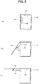
Figs. 2(a) to 2(c) are cross sectional views each illustrating relation between the open and closed state of the door and the operation of the stay; -
Fig. 3 is a substantial part cross sectional view of the stay for opening and closing of the door; -
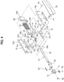
Fig. 4 is an exploded perspective view of the stay for opening and closing of the door; - Fiq. 5 is an exploded perspective view of an arm slider;
-
Fig. 6 is a cross sectional view of an arm and a slider; -
Figs. 7(a) and 7(b) are cross sectional views of the arm installed on the door and the slider (Fig. 7(a) illustrates a space provided between an arm main body and a friction plate andFig. 7(b) illustrates the arm main body and the frictional plate that are in close contact with each other); -
Figs. 8(a) to 8(c) are operational views of a slider crank mechanism (Fig. 8(a) illustrates the door in the open state,Fig. 8(b) illustrates the slider crank mechanism that has reached a change point, andFig. 8(c) illustrates the door in the closed state) ; -
Figs. 9(a) and 9(b) are views each illustrating a torque that acts on the arm by the slider crank mechanism (Fig. 9 (a) illustrates an example of the present invention in which the pins are changed andFig. 9(b) illustrates an embodiment which does not form part of the invention); -
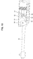
Fig. 10 is a substantial part cross sectional view of a stay for opening and closing of a door according to a second embodiment of the present invention; -
Fig. 11 is a substantial part cross sectional view of a stay for opening and closing of a door according to a third embodiment of the present invention; and -
Figs. 12(a) 12(b) are cross sectional views of a conventional stay for opening and closing of a door (Fig. 12(a) illustrates the door in the closed state andFig. 12 (b) illustrates the door in the open state). - With reference to the attached drawings, a stay for opening and closing of a door (hereinafter referred to as "stay") according to the first embodiment of the present invention will be described in detail below.
Fig. 1 is a perspective view of ahousing 11 and adoor 12 on which the stay for opening and closing of a door is mounted. The stay has amain body 15 fixed to thehousing 11 and anarm 14 connected to thedoor 12 side. Thearm 14 is mounted to themain body 15 rotatable in the vertical plane. When opening and closing thedoor 12, thearm 14 gives the door 12 a biasing force for assisting opening and closing of thedoor 12. Between thehousing 11 and thedoor 12, aslid hinge 13 is mounted in addition to the stay. The rotation orbit of thedoor 12 is determined by theslide hinge 13. Here, theslide hinge 13 is a well-known hinge which rotation axis moves when thedoor 12 gets open. As the rotation axis of theslide hinge 13 moves, when thedoor 12 gets open, the clearance between the frame of thehousing 11 and thedoor 12 can be made smaller. - As illustrated in
Fig. 1 , amain body 15 of the stay is mounted on an upper part of aside plate 11a of thehousing 11. A side 11a1 at the ceiling side of theside plate 11a is orthogonal to a side 11a2 at the frame side and themain body 15 is mounted to be positioned at the corner of these sides. In thearm 14, anarm slider 16 is mounted slidable in the longitudinal direction of thearm 14. A mountingseat 17 is rotatably connected to thearm slider 16. Thedoor 12 is attached to this mountingseat 17. - As illustrated in
Figs. 2 (a) to 2(c) , thearm 14 of the stay extends in approximately parallel to thedoor 12. When opening and closing thedoor 12, thearm 14 rotates relative to themain body 15 while it is kept in approximately parallel to thedoor 12. As illustrated inFig. 12(a) , when thedoor 12 is in the closed state, thearm 14 gives thedoor 12 an additional force in the closing direction. Therefore, thedoor 12 is kept stable in the closed state. As illustrated inFig. 2(b) , when theclosed door 12 gets open, for example, 20 degrees or more, then, thearm 14 gives the door 12 a force in the opening direction. This force of thearm 14 in the opening direction facilitates the opening operation of thedoor 12 and makes it possible to keep any open angle of the door fixed. As illustrated inFig. 2(c) , thedoor 12 can open 90 degrees at the maximum. When closing theopen door 12, if thedoor 12 gets closed up to 20 degrees, for example, (Fig. 2(c) to Fig. 2(b) ), thedoor 12 closes automatically (Fig. 2(a) ). In this embodiment, thedoor 12 is set out of the frame of thehousing 11, or it is provided to cover the frame of thehousing 11. -
Fig. 3 is a substantial part cross sectional view of the stay andFig. 4 is an exploded perspective view of the stay. As illustrated inFig. 3 , the slider crankmechanism 21 is built in themain body 15. The slider crankmechanism 21 has thearm 14, alink 23 connected to anarm holding plate 22 of thearm 14, and a main-body slider 24 provided at themain body 15 to be slidable in one direction. The weight of thedoor 12 is supported by the biasing force of acoil spring 25 as an elastic body contained in themain body 15. In other words, the biasing force F1 of thecoil spring 25 is converted to a torque T1 of thearm 14 by the main-body slider 24 and thelink 23. The weight of the door can be supported by the torque T1 of thearm 14. - As illustrated in
Fig. 2(c) , when thedoor 12 is in the open state, thearm 14 is given a torque in the clockwise direction (in the opening direction of the door 12) by the biasing force of thecoil spring 24. When thedoor 12 gets closed, for example, 20 degrees or less, the slider crank mechanism reaches the change point. As illustrated inFig. 2(a) , when thedoor 12 gets further closed, thearm 14 is given a torque in the counterclockwise direction (in the closing direction of the door 12) by the biasing force of thecoil spring 25. This torque can be used by a catch force of theclosed door 12. - As illustrated in
Fig. 4 , themain body 15 is combination of two-divided casehalf bodies case half bodies case half bodies guide walls guide walls body slider 24 andspring receiver 28 are accommodated to be slidable in one direction along theguide walls arm 14 is provided to run between the pairedcase half bodies main body 15 is covered with a decoratedcover 29. - An end of the
arm 14 is rotatably connected to themain body 15 via the pin P1. The pin P1 is a pivot of the arm relative to themain body 15. Thearm 14 has an elongating and hollow armmain body 30, a pair ofarm holding plates 22 mounted to an end of the armmain body 30 and acylindrical bearing 19 provided between the pairedarm holding plates 22. - A cross section of the arm
main body 30 is a flat box. At an end of the armmain body 30, a mountinghole 30a is formed for mounting the pairedarm holding plates 22. Each of the pairedarm holding plates 22 has a connectingpart 22a elongating in accordance with the armmain body 30 and anenlarged part 22b which is enlarged relative to the connectingpart 22a. The connectingpart 22a of eacharm holding plate 22 is inserted to an end of the armmain body 30. After the pairedarm holding plates 22 and the armmain body 30 are connected to each other with thepin 18, an end of the armmain body 30 is covered with a frame-shaped fixation piece. An end in the opposite direction of the armmain body 30 is covered with aplug 35. - On the inner circumference of the
bearing 19, the pin P1 is fit therein. Rotation of thearm 14 relative to the pin P1 is guided by thisbearing 19. Alink 23 is rotatably connected to thearm holding plates 22 via a pin P2. The pin P2, which is a pivot of thelink 23 relative to thearm 14, is positioned in thearm holding plates 22 to be shifted in a plane from the pin P1 which is the pivot of thearm 14 relative to themain body 15. - Between the main-
body slider 24 and thespring receiver 28, a plurality of coil springs 25 is accommodated. The plural coil springs 25 have one longitudinal ends inserted into plural cylindrical recesses of the main-body slider 24. The other ends are inserted into plural cylindrical recesses of thespring receiver 28. The coil springs 25 are sandwiched between the main-body slider 24 and thespring receiver 28. The main-body slider 24 and thespring receiver 28 are slidable in one direction by theguide walls case half bodies spring receiver 28 is provided to run between the pairedcase half bodies spring receiver 28, along hole 28a is formed for insertion of the pin P5. By thecoil spring 25, thespring receiver 28 is acted upon by a biasing force in the right and back direction in the figure. Sliding in the right and back direction of thespring receiver 28 is restricted by the pin P5. Here, the main-body slider 24 and thespring receiver 28 take identical shapes. This is because a single die is used in injection molding of both of the main-body slider 24 and thespring receiver 28. - At an end of the main-
body slider 24, a mountain-shapedprojection 24a is formed. In thisprojection 24a, arecess 24b and along hole 24c are formed as two pin receivers corresponding to the two pins P3 and P4 of thelink 23. Out of the two pins, the pin P4 is inserted into thelong hole 24c and the other pin P3 is fit in therecess 24b. - The
link 23 is combination of two parallel link plates connected by a bottom plate and has a U-shaped cross section. An end of thelink 23 is rotatably connected to thearm holding plates 22 via the pin P2. At the other end of thelink 23, the above-mentioned two pins P3 and P4 are provided. - To the arm
main body 30, thearm slider 16 is mounted slidable in the longitudinal direction of the armmain body 30. As illustrated inFig. 5 , thearm slider 16 has a frame-shaped slidermain body 31 surrounding the armmain body 30, aposition adjusting screw 32 fit in the slidermain body 31 and afriction plate 33 provided between the armmain body 30 and slidermain body 31. - In the slider
main body 31, a mountain-shapedprojection 31a is formed. The mountingseat 17 is rotatably mounted to thisprojection 31a via a pin P6. The mountingseat 17 has a plate-shaped platemain body 17a and an approximatelytriangular projection plate 17b projecting downward from the platemain body 17a. In the platemain body 17a, a throughhole 17d is formed for installing on thedoor 12. In theprojection plate 17b, ahole 17c is formed for insertion of the pin P6. The mountingseat 17 rotates around the pin P6. - At the bottom of the slider main body, a
female screw part 36 is fit therein. Thefemale screw part 36 has a cylindrical female screwmain body 36a having an inner circumference on which a female screw is formed and a square-shapedflange 36b provided integrally at the upper end of the female screwmain body 36a. As illustrated inFig. 6 , the female screwmain body 36a of thefemale screw part 36 is fit in thehole 31b at the bottom of the slidermain body 31. Theflange 36b of thefemale screw part 36 is placed on the upper surface of the bottom of the slidermain body 31. In thefemale screw part 36, aposition adjusting screw 32 is turned from the outside. Theposition adjusting screw 32 is covered with a decoratedplate 37 for improving the appearance and preventing theposition adjusting screw 32 from turning carelessly. The decoratedplate 37 is pressed and fixed to ahook 31c of the slidermain body 31. - The
friction plate 33 is provided between the armmain body 30 and the slidermain body 31. Thefriction plate 33 is made of springy synthetic resin. On a contact surface of thefriction plate 33 with the armmain body 30, a one-step raisedcontact part 33a (seeFig. 5 ) is formed. On a back surface of thefriction plate 33, anotch 33b is formed corresponding to theflange 36b of thefemale screw part 36. As theflange 36b of thefemale screw part 36 is fit in thenotch 33b of thefriction plate 33, thefriction plate 33 is able to slide together with the slidermain body 31. - The
friction plate 33 goes back and forth toward the armmain body 30 by the action of feed screw of theposition adjusting screw 32. By adjusting a contact pressure of thefriction plate 33 with the armmain body 30, the resistance when the slidermain body 31 slides relative to the armmain body 30 is adjusted. As illustrated inFig. 7(a) , in order to facilitate opening of thedoor 12, a space is provided between the armmain body 30 and thefriction plate 33. On the other hand, as illustrated inFig. 7(b) , in order to make it difficult to open thedoor 12, the space between the armmain body 30 and thefriction plate 33 is removed so that the armmain body 30 is in close contact with thefriction plate 33. - As illustrated in
Fig. 4 again, adamper 41 for generating a damping force by viscosity resistance of a fluid is build in themain body 15. When thearm 14 rotates a predetermined angle or more, thearm 14 comes into contact with amovable part 42 of thedamper 41 and thedamper 41 is compressed. With compression of thedamper 41, a force of damping rotation is given to thearm 14. As thedamper 41 is provided, it is possible to reduce the impact of thedoor 12 when it gets closed and comes into collision with thehousing 11. - As illustrated in
Figs. 8 (a) to 8(c) , thearm 14, thelink 23 and the main-body slider 24 of the stay form the slider crankmechanism 21. As illustrated inFig. 8(a) , when thedoor 12 is open, the pin P4 of thelink 23 is fit at the right end of thelong hole 24c of the main-body slider 24. In this state, the pivot of thelink 23 relative to the main-body slider 24 is the pin P4. The biasing force of the coil springs 25 contained in themain body 15 is transmitted, as a torque, via the pin P4, thelink 23 and the pin P2 to thearm 14 which is equivalent to a crank. When thedoor 12 is open, an additional torque in the opening direction of thedoor 12 acts on thearm 14. - As illustrated in
Fig. 8(b) , when thedoor 12 is rotated in the closing direction (thearm 14 is rotated in the counterclockwise direction relative to the main body 15), the slider crankmechanism 21 reaches the change point. In other words, thearm 14 can rotates both in the counterclockwise direction and in the clockwise direction, and the torque from the coil springs 25 is not transmitted to thearm 14. - As illustrated in
Fig. 8(c) , when thedoor 12 is further rotated in the closing direction (thearm 14 is further rotated in the counterclockwise direction relative to the main body 15), the slider crank mechanism goes beyond the change point and the torque in the closing direction of thedoor 12 acts on thearm 14 by the biasing force of the coil springs 25. - In the stay using the slider crank
mechanism 21 like in the present embodiment, the weight of thedoor 12 is supported by the biasing force of the coil springs 25. Then, the biasing force of the coil springs 25 is also used in a catch force in the closing direction of thedoor 12 by using the change point of the slider crankmechanism 21. When thedoor 12 is heavy, it is necessary to support thedoor 12 by strengthening the biasing force of the coil springs 25. However, if the biasing force is strengthened, the catch force is strengthened thereby to increase the load of opening thedoor 12. In order to prevent this, in the present embodiment, as illustrated inFigs. 8(b) and 8(c) , the pivot of thelink 23 relative to the main-body slider 24 is changed from the pin P4 to the pin P3. That is, as illustrated inFig. 8(c) , when thelink 23 rotates, the pin P4 fit in the right end of thelong hole 24c of the main-body slider 24 is lifted up and instead, the pin P3 is fit in therecess 24b of the main-body slider 24. Then, the pivot of thelink 23 relative to the main-body slider 24 is changed from the pin P4 to the pin P3. - As illustrated in
Fig. 9(a) , a force F is transmitted from thelink 23 to thearm 14 in a direction connecting the pin P3 of thelink 23 to the pin P2. The torque transmitted to thearm 14 is expressed by the force F x the arm length L. The arm length L' is expressed by a distance from the pivot of the arm 14 (pin P1) to the line L1 connecting the pin P3 and the pin P2 of thelink 23 . As the pin as pivot of thelink 23 relative to the main-body slider 24 is changed from P4 to P3, the arm length L' can be shortened. This makes it possible to reduce the torque on thearm 14 and to reduce the catch force of thedoor 12 in the closed state. -
Fig. 9(b) illustrates a comparative example when the pin is not changed, which does not form part of the invention. If the pin is not changed, the arm length L gets longer. Therefore, F x L cannot be reduced and the torque that acts on thearm 14 also cannot be reduced. -
Fig. 10 is a substantial part cross sectional view of a stay for opening and closing of a door according to a second embodiment of the present invention. In this embodiment, like the stay for opening and closing of a door according to the first embodiment described above, a slider crankmechanism 52 is built in amain bodv 51. The slider crankmechanism 52 has anarm 52, alink 55 connected to arm holdingplates 54 of thearm 53 and a main-body slider 56 provided on themain body 51 to be slidable in one direction. However, in the stay according to the second embodiment, twopins 57 are provided on the main-body slider 56 and twopin receivers 58 are provided on thelink 55 corresponding to the twopins 57, which is different from that in the stay according to the above-described first embodiment. The pivot of thelink 55 is switched between thepins 57 by rotation of thelink 55 relative to the main-body slider 56, like in the above-described first embodiment. -
Fig. 11 is a substantial part cross sectional view of a stay for opening and closing of a door according to a third embodiment of the present invention. In this embodiment, like the stay for opening and closing of a door according to the first embodiment described above, a slider crankmechanism 62 is built in amain body 61. The slider crankmechanism 62 has anarm 62, alink 65 connected to arm holdingplates 64 of thearm 63 and a main-body slider 66 provided on themain body 61 to be slidable in one direction. However, in the stay according to the third embodiment, twopins 67 are provided on thearm holding plates 64 and twopin receivers 68 are provided on thelink 65 corresponding to the twopins 67, which is different from those in the stays according to the above-described first and second embodiments. The pivot of thelink 65 is switched between thepins 67 by rotation of thelink 65 relative to thearm holding plates 64, like in the above-described first and second embodiments. - Here, the present invention is not limited to the above-described embodiments and may be embodied in various forms without departing from the scope of the present invention, as defined by the appended claims.
- Further, three or more pins may be provided as axes of rotation in the arm, link and main-body slider, or two pins may be provided in the arm and link or the link and main-body slider.
-
- 11
- housing
- 12
- door
- 14, 53, 63
- arm
- 15, 51, 61
- main body
- 16
- arm slider
- 17
- mounting seat
- 23, 55, 65
- link
- 24b
- recess (pin receiver)
- 24c
- long hole (pin receiver)
- 24, 56, 66
- main-body slider
- 31
- slider main body
- 32
- position adjusting screw
- 33
- friction plate
- P1 to P5
- pin
Claims (1)
- A stay for opening and closing of a door or a cover (12), comprising:a main body (15, 51, 61) mounted to a housing (11);an arm (14, 53, 63) having one end rotatably connected to the main body (15, 51, 61);a main-body slider (24, 56, 66) slidably provided on the main body (15, 51, 61) and being biased in one direction by an elastic body (25); anda link (23, 55, 65) rotatably connected to the main-body slider (24, 56, 66) and the arm (14, 53, 63),characterized in thatthe arm (14, 53, 63) is configured to give the door or cover (12), in an open state, an additional force in an opening direction and to give the door or cover (12), in a closed state, an additional force in a closing direction,
in that there are at least two pivots of the link (23, 55, 65) in the form of pins (P3,P4,57,67) relative to the arm (14, 53, 63) or the main-body slider (24, 56, 66), and in that when the door or cover (12) rotates from the open state to the closed state, the pivots of the link (23, 55, 65) relative to the arm (14, 53, 63) or the main-body slider (24, 56, 66) are changed from one pin (P4,57,67) to an opposite pin (P3,57,67) so as to reduce the force in the closing direction given by the arm (14, 53, 63) to the door or cover (12).
Applications Claiming Priority (3)
| Application Number | Priority Date | Filing Date | Title |
|---|---|---|---|
| JP2009045498 | 2009-02-27 | ||
| PCT/JP2009/069822 WO2010097996A1 (en) | 2009-02-27 | 2009-11-25 | Stay for opening and closing of door |
| EP09840843.8A EP2402536A4 (en) | 2009-02-27 | 2009-11-25 | Stay for opening and closing of door |
Related Parent Applications (1)
| Application Number | Title | Priority Date | Filing Date |
|---|---|---|---|
| EP09840843.8A Division EP2402536A4 (en) | 2009-02-27 | 2009-11-25 | Stay for opening and closing of door |
Publications (3)
| Publication Number | Publication Date |
|---|---|
| EP2821578A2 EP2821578A2 (en) | 2015-01-07 |
| EP2821578A3 EP2821578A3 (en) | 2015-02-25 |
| EP2821578B1 true EP2821578B1 (en) | 2019-08-28 |
Family
ID=42665217
Family Applications (2)
| Application Number | Title | Priority Date | Filing Date |
|---|---|---|---|
| EP09840843.8A Withdrawn EP2402536A4 (en) | 2009-02-27 | 2009-11-25 | Stay for opening and closing of door |
| EP14003061.0A Not-in-force EP2821578B1 (en) | 2009-02-27 | 2009-11-25 | Stay for opening and closing of door |
Family Applications Before (1)
| Application Number | Title | Priority Date | Filing Date |
|---|---|---|---|
| EP09840843.8A Withdrawn EP2402536A4 (en) | 2009-02-27 | 2009-11-25 | Stay for opening and closing of door |
Country Status (9)
| Country | Link |
|---|---|
| US (1) | US8894162B2 (en) |
| EP (2) | EP2402536A4 (en) |
| JP (2) | JP5026583B2 (en) |
| KR (3) | KR101323939B1 (en) |
| CN (2) | CN102027181B (en) |
| ES (1) | ES2749231T3 (en) |
| HK (1) | HK1153252A1 (en) |
| SG (2) | SG174168A1 (en) |
| WO (1) | WO2010097996A1 (en) |
Cited By (1)
| Publication number | Priority date | Publication date | Assignee | Title |
|---|---|---|---|---|
| WO2023232308A1 (en) | 2022-06-01 | 2023-12-07 | Emuca S.A | Lift-up door movement device |
Families Citing this family (34)
| Publication number | Priority date | Publication date | Assignee | Title |
|---|---|---|---|---|
| JP5415491B2 (en) * | 2011-07-29 | 2014-02-12 | スガツネ工業株式会社 | Door opening / closing device unit and method of mounting the door opening / closing device unit |
| JP5415490B2 (en) | 2011-07-29 | 2014-02-12 | スガツネ工業株式会社 | Door opening / closing device with support member and support member for door opening / closing device |
| JP5424361B2 (en) * | 2011-12-19 | 2014-02-26 | Necインフロンティア株式会社 | Wall-mounted casing device and electronic device |
| WO2013183369A1 (en) * | 2012-06-04 | 2013-12-12 | スガツネ工業株式会社 | Washer position adjusting mechanism, and piece of furnuture having washer position adjusting mechanism installed therein |
| US9353562B2 (en) | 2012-09-25 | 2016-05-31 | Sugatsune Kogyo Co., Ltd. | Door opening and closing device |
| JP5823610B2 (en) * | 2012-12-11 | 2015-11-25 | スガツネ工業株式会社 | Stay |
| AT514720B1 (en) * | 2013-08-30 | 2016-03-15 | Blum Gmbh Julius | locking device |
| JP6193159B2 (en) * | 2014-03-14 | 2017-09-06 | 株式会社ニフコ | Ventilation door opening and closing mechanism |
| AT515492B1 (en) * | 2014-03-14 | 2020-01-15 | Blum Gmbh Julius | Actuator for furniture flaps |
| DE102014113970B4 (en) * | 2014-09-26 | 2016-08-18 | Samet Kalip Ve Maden Esya San. Ve Tic. A.S. | hinge |
| US20160218021A1 (en) * | 2015-01-27 | 2016-07-28 | Advanced Semiconductor Engineering, Inc. | Semiconductor package and method of manufacturing the same |
| US10590688B2 (en) * | 2015-02-17 | 2020-03-17 | Arturo Salice S.P.A. | Lifting system for leaves of furniture |
| DE102015102393A1 (en) * | 2015-02-19 | 2016-08-25 | Hettich Holding Gmbh & Co. Ohg | swivel fitting |
| WO2016174076A1 (en) * | 2015-04-30 | 2016-11-03 | Arturo Salice S.P.A. | Hinge for furniture leaves that swing about at least one horizontal axis |
| DE102015117291C5 (en) * | 2015-10-09 | 2020-03-26 | Samet Kalip Ve Maden Esya San. Ve Tic. A.S. | Flap holder for a furniture flap |
| CN105201317B (en) * | 2015-10-14 | 2017-03-29 | 伍志勇 | A kind of upper turning-up devices it is adjustable on turn over effort-saving mechanism |
| ITUB20156022A1 (en) * | 2015-11-30 | 2017-05-30 | Leandro Cappellotto | MOVEMENT MECHANISM OF FURNITURE DOORS |
| WO2017221716A1 (en) * | 2016-06-21 | 2017-12-28 | スガツネ工業株式会社 | Stay |
| AT518253B1 (en) * | 2016-06-22 | 2017-09-15 | Blum Gmbh Julius | Actuator for furniture parts |
| IT201600098088A1 (en) * | 2016-09-30 | 2018-03-30 | Salice Arturo Spa | Control device for a lifting system and lifting system for furniture doors. |
| US11168502B2 (en) * | 2017-05-24 | 2021-11-09 | Sugatsune Kogyo Co., Ltd. | Door device |
| IT201700112315A1 (en) * | 2017-10-06 | 2019-04-06 | Effegi Brevetti Srl | AUTOMATIC OPENING MECHANISM FOR HINGED DOORS |
| WO2019141137A1 (en) * | 2018-01-16 | 2019-07-25 | 东莞市楷模家居用品制造有限公司 | Support apparatus and folding furniture provided with support apparatus |
| EP3816384A4 (en) * | 2018-06-29 | 2022-03-30 | Sugatsune Kogyo Co. Ltd. | Stay |
| CN109157068A (en) * | 2018-10-25 | 2019-01-08 | 浙江百福玛制冷科技有限公司 | It is a kind of to facilitate the sandwich cabinet for placing article |
| US10697220B2 (en) * | 2018-10-29 | 2020-06-30 | Toshiba Tec Kabushiki Kaisha | Counterbalance door dampener system and method for automatic duplexing units |
| IT201800009883A1 (en) * | 2018-10-30 | 2020-04-30 | Effegi Brevetti Srl | MECHANISM FOR HANDLING A FLAP DOWNWARDS |
| JP7207723B2 (en) * | 2019-05-08 | 2023-01-18 | 株式会社ベスト | Lever stopper with self-closing device |
| AT522458B1 (en) * | 2019-05-17 | 2020-11-15 | Blum Gmbh Julius | Furniture fittings |
| AT522656A1 (en) * | 2019-05-17 | 2020-12-15 | Blum Gmbh Julius | Furniture drive |
| CN111543797B (en) * | 2020-03-04 | 2021-07-09 | 江苏科技大学 | Intelligent key storage cabinet body and working method thereof |
| JP2022085726A (en) * | 2020-11-27 | 2022-06-08 | 株式会社ナチュラレーザ・ワン | Hinge and office machine using this hinge |
| US11846387B2 (en) * | 2021-03-04 | 2023-12-19 | Van Murphy Bed LLC | Bracket with rotatable and cantilevered support member |
| CN113482476B (en) * | 2021-07-17 | 2023-02-03 | 广东东泰五金精密制造有限公司 | A press and open resetting means for furniture |
Family Cites Families (29)
| Publication number | Priority date | Publication date | Assignee | Title |
|---|---|---|---|---|
| US1335429A (en) * | 1919-08-28 | 1920-03-30 | Danielson Albin | Casement-adjuster |
| US1794477A (en) * | 1927-07-16 | 1931-03-03 | Sodergren Eric | Regulator for windows and doors |
| US2727776A (en) * | 1953-06-05 | 1955-12-20 | Herbert N Brownlee | Window opener and fastener |
| DE1654437C3 (en) | 1967-02-03 | 1976-01-08 | Alno-Moebelwerke Gmbh & Co Kg, 7798 Pfullendorf | Fitting for a foldable closet door or the like |
| US3575483A (en) * | 1969-09-03 | 1971-04-20 | Lane Co Inc | Drop front cabinet having tiltable bin with adjustable tensioning and stop device |
| US3765053A (en) * | 1972-08-28 | 1973-10-16 | Magnavox Co | Friction support for lids |
| US3906587A (en) * | 1973-12-07 | 1975-09-23 | Weber Knapp Co | Lid mounting hinge and counterbalance mechanism |
| JP2818892B2 (en) | 1989-10-02 | 1998-10-30 | 大塚製薬 株式会社 | Foam formulation |
| JP3025023B2 (en) | 1990-12-12 | 2000-03-27 | 日本発条株式会社 | Vehicle impact beam |
| JP2506976Y2 (en) * | 1992-10-29 | 1996-08-14 | 新関西ベアリング株式会社 | Openness adjuster |
| US5401096A (en) * | 1993-05-17 | 1995-03-28 | Columbia Manufacturing Company, Inc. | Spring-controlled support arm for a desk top |
| US6296337B1 (en) * | 1994-08-24 | 2001-10-02 | Sugatsune Industrial Co., Ltd. | Overhead doors |
| JP3271450B2 (en) * | 1994-12-22 | 2002-04-02 | 村田機械株式会社 | Cover lock mechanism |
| DE29604354U1 (en) * | 1996-03-08 | 1996-06-05 | Salice Arturo Spa | Retaining fitting for a flap hinged to a top wall of a cabinet about a horizontal pivot axis |
| JP3120212B2 (en) | 1996-05-15 | 2000-12-25 | スガツネ工業株式会社 | Door opening / closing damper |
| TW334493B (en) | 1996-05-14 | 1998-06-21 | Sugatsune Kogyo | Damper for opening or closing a door |
| JPH1082233A (en) * | 1996-09-05 | 1998-03-31 | Tostem Corp | Sash |
| US5931554A (en) * | 1997-08-29 | 1999-08-03 | General Electric Company | Refrigerator door stop |
| EP1050230A1 (en) | 1999-05-07 | 2000-11-08 | KARL SIMON GmbH & Co. KG | Opening support for a chest |
| JP3494603B2 (en) * | 1999-10-20 | 2004-02-09 | スガツネ工業株式会社 | Stay |
| JP4040355B2 (en) * | 2002-04-26 | 2008-01-30 | スガツネ工業株式会社 | Hinge |
| DE20311189U1 (en) * | 2003-07-21 | 2003-09-25 | Salice Arturo Spa | Lifting device for a two-leaf folding flap or door |
| DE202005021541U1 (en) * | 2004-07-14 | 2008-08-28 | Julius Blum Gmbh | Actuation mechanism for a pivotally mounted actuator arm |
| JP2006063748A (en) * | 2004-08-30 | 2006-03-09 | Nhk Spring Co Ltd | Opening/closing mechanism assembly for frap gate door |
| TWI262241B (en) * | 2004-09-22 | 2006-09-21 | Asia Optical Co Inc | Knuckle arm |
| AT414257B (en) * | 2004-10-12 | 2006-10-15 | Blum Gmbh Julius | HOLDING AND ADJUSTMENT DEVICE FOR MOVING FURNITURE PARTS |
| AT501065A1 (en) * | 2004-11-18 | 2006-06-15 | Blum Gmbh Julius | ACTUATOR FOR MOVING A FURNITURE FLAP |
| AT502938A1 (en) * | 2004-11-18 | 2007-06-15 | Blum Gmbh Julius | ACTUATOR FOR MOVING A FLAP OF A FURNITURE |
| JP2009045498A (en) | 2008-12-03 | 2009-03-05 | Sri Sports Ltd | Golf ball |
-
2009
- 2009-11-25 EP EP09840843.8A patent/EP2402536A4/en not_active Withdrawn
- 2009-11-25 CN CN200980117575.9A patent/CN102027181B/en not_active Expired - Fee Related
- 2009-11-25 US US13/203,134 patent/US8894162B2/en active Active
- 2009-11-25 JP JP2010503291A patent/JP5026583B2/en active Active
- 2009-11-25 SG SG2011061975A patent/SG174168A1/en unknown
- 2009-11-25 KR KR1020137012208A patent/KR101323939B1/en not_active IP Right Cessation
- 2009-11-25 SG SG2013015821A patent/SG188842A1/en unknown
- 2009-11-25 EP EP14003061.0A patent/EP2821578B1/en not_active Not-in-force
- 2009-11-25 ES ES14003061T patent/ES2749231T3/en active Active
- 2009-11-25 KR KR1020117016843A patent/KR20110104968A/en active Application Filing
- 2009-11-25 KR KR1020137022622A patent/KR101412839B1/en not_active IP Right Cessation
- 2009-11-25 CN CN201310347105.XA patent/CN103452414B/en active Active
- 2009-11-25 WO PCT/JP2009/069822 patent/WO2010097996A1/en active Application Filing
-
2011
- 2011-07-15 HK HK11107372.0A patent/HK1153252A1/en not_active IP Right Cessation
-
2012
- 2012-02-15 JP JP2012030105A patent/JP5240955B2/en active Active
Non-Patent Citations (1)
| Title |
|---|
| None * |
Cited By (1)
| Publication number | Priority date | Publication date | Assignee | Title |
|---|---|---|---|---|
| WO2023232308A1 (en) | 2022-06-01 | 2023-12-07 | Emuca S.A | Lift-up door movement device |
Also Published As
| Publication number | Publication date |
|---|---|
| SG174168A1 (en) | 2011-10-28 |
| JP2012092649A (en) | 2012-05-17 |
| ES2749231T3 (en) | 2020-03-19 |
| JP5026583B2 (en) | 2012-09-12 |
| CN103452414B (en) | 2016-08-10 |
| JPWO2010097996A1 (en) | 2012-08-30 |
| KR20130102132A (en) | 2013-09-16 |
| EP2821578A3 (en) | 2015-02-25 |
| CN102027181B (en) | 2014-08-27 |
| KR20110104968A (en) | 2011-09-23 |
| JP5240955B2 (en) | 2013-07-17 |
| KR101412839B1 (en) | 2014-06-27 |
| EP2821578A2 (en) | 2015-01-07 |
| KR20130058765A (en) | 2013-06-04 |
| HK1153252A1 (en) | 2012-03-23 |
| KR101323939B1 (en) | 2013-10-31 |
| EP2402536A4 (en) | 2014-03-12 |
| US8894162B2 (en) | 2014-11-25 |
| US20120000130A1 (en) | 2012-01-05 |
| CN103452414A (en) | 2013-12-18 |
| EP2402536A1 (en) | 2012-01-04 |
| CN102027181A (en) | 2011-04-20 |
| SG188842A1 (en) | 2013-04-30 |
| WO2010097996A1 (en) | 2010-09-02 |
Similar Documents
| Publication | Publication Date | Title |
|---|---|---|
| EP2821578B1 (en) | Stay for opening and closing of door | |
| EP1555372B1 (en) | Hinge device | |
| JP6893688B2 (en) | Switchgear switchgear and various switchgear equipped with this switchgear switchgear | |
| EP3633128B1 (en) | Device for doors | |
| US20150240546A1 (en) | Door opening and closing device | |
| CA2982156C (en) | Furniture hinge comprising a damper | |
| US20180155974A1 (en) | Furniture hinge comprising a damper and a spring | |
| US10788785B2 (en) | Document cover closer and office equipment having the same | |
| WO2012011330A1 (en) | Door opening/closing mechanism and refrigerator | |
| JP6819998B2 (en) | Door body opening / closing device and various cabinets equipped with this door body opening / closing device | |
| CN218509269U (en) | Hinge with elastic hinge | |
| KR101802639B1 (en) | A Stopper hinge for heavy equipment | |
| CN113874590A (en) | Hinge device | |
| CN106766586B (en) | Left-right door opening mechanism and refrigerator | |
| JP4990999B2 (en) | Door opening / closing mechanism and refrigerator | |
| JP4246057B2 (en) | Hinge with damper | |
| JP4833349B1 (en) | Door opening / closing mechanism and refrigerator | |
| KR20220055672A (en) | Swing motion open and closed type charging door device for electric vehicle with rotating handle structure |
Legal Events
| Date | Code | Title | Description |
|---|---|---|---|
| PUAI | Public reference made under article 153(3) epc to a published international application that has entered the european phase |
Free format text: ORIGINAL CODE: 0009012 |
|
| 17P | Request for examination filed |
Effective date: 20140904 |
|
| AC | Divisional application: reference to earlier application |
Ref document number: 2402536 Country of ref document: EP Kind code of ref document: P |
|
| AK | Designated contracting states |
Kind code of ref document: A2 Designated state(s): AT BE BG CH CY CZ DE DK EE ES FI FR GB GR HR HU IE IS IT LI LT LU LV MC MK MT NL NO PL PT RO SE SI SK SM TR |
|
| PUAL | Search report despatched |
Free format text: ORIGINAL CODE: 0009013 |
|
| AK | Designated contracting states |
Kind code of ref document: A3 Designated state(s): AT BE BG CH CY CZ DE DK EE ES FI FR GB GR HR HU IE IS IT LI LT LU LV MC MK MT NL NO PL PT RO SE SI SK SM TR |
|
| RIC1 | Information provided on ipc code assigned before grant |
Ipc: E05F 1/10 20060101AFI20150121BHEP |
|
| R17P | Request for examination filed (corrected) |
Effective date: 20150814 |
|
| RBV | Designated contracting states (corrected) |
Designated state(s): AT BE BG CH CY CZ DE DK EE ES FI FR GB GR HR HU IE IS IT LI LT LU LV MC MK MT NL NO PL PT RO SE SI SK SM TR |
|
| GRAP | Despatch of communication of intention to grant a patent |
Free format text: ORIGINAL CODE: EPIDOSNIGR1 |
|
| STAA | Information on the status of an ep patent application or granted ep patent |
Free format text: STATUS: GRANT OF PATENT IS INTENDED |
|
| INTG | Intention to grant announced |
Effective date: 20190308 |
|
| GRAS | Grant fee paid |
Free format text: ORIGINAL CODE: EPIDOSNIGR3 |
|
| GRAA | (expected) grant |
Free format text: ORIGINAL CODE: 0009210 |
|
| STAA | Information on the status of an ep patent application or granted ep patent |
Free format text: STATUS: THE PATENT HAS BEEN GRANTED |
|
| AC | Divisional application: reference to earlier application |
Ref document number: 2402536 Country of ref document: EP Kind code of ref document: P |
|
| AK | Designated contracting states |
Kind code of ref document: B1 Designated state(s): AT BE BG CH CY CZ DE DK EE ES FI FR GB GR HR HU IE IS IT LI LT LU LV MC MK MT NL NO PL PT RO SE SI SK SM TR |
|
| REG | Reference to a national code |
Ref country code: GB Ref legal event code: FG4D |
|
| REG | Reference to a national code |
Ref country code: CH Ref legal event code: EP |
|
| REG | Reference to a national code |
Ref country code: AT Ref legal event code: REF Ref document number: 1172614 Country of ref document: AT Kind code of ref document: T Effective date: 20190915 |
|
| REG | Reference to a national code |
Ref country code: IE Ref legal event code: FG4D |
|
| REG | Reference to a national code |
Ref country code: DE Ref legal event code: R096 Ref document number: 602009059663 Country of ref document: DE |
|
| REG | Reference to a national code |
Ref country code: NL Ref legal event code: MP Effective date: 20190828 |
|
| REG | Reference to a national code |
Ref country code: LT Ref legal event code: MG4D |
|
| PG25 | Lapsed in a contracting state [announced via postgrant information from national office to epo] |
Ref country code: FI Free format text: LAPSE BECAUSE OF FAILURE TO SUBMIT A TRANSLATION OF THE DESCRIPTION OR TO PAY THE FEE WITHIN THE PRESCRIBED TIME-LIMIT Effective date: 20190828 Ref country code: HR Free format text: LAPSE BECAUSE OF FAILURE TO SUBMIT A TRANSLATION OF THE DESCRIPTION OR TO PAY THE FEE WITHIN THE PRESCRIBED TIME-LIMIT Effective date: 20190828 Ref country code: SE Free format text: LAPSE BECAUSE OF FAILURE TO SUBMIT A TRANSLATION OF THE DESCRIPTION OR TO PAY THE FEE WITHIN THE PRESCRIBED TIME-LIMIT Effective date: 20190828 Ref country code: NL Free format text: LAPSE BECAUSE OF FAILURE TO SUBMIT A TRANSLATION OF THE DESCRIPTION OR TO PAY THE FEE WITHIN THE PRESCRIBED TIME-LIMIT Effective date: 20190828 Ref country code: NO Free format text: LAPSE BECAUSE OF FAILURE TO SUBMIT A TRANSLATION OF THE DESCRIPTION OR TO PAY THE FEE WITHIN THE PRESCRIBED TIME-LIMIT Effective date: 20191128 Ref country code: BG Free format text: LAPSE BECAUSE OF FAILURE TO SUBMIT A TRANSLATION OF THE DESCRIPTION OR TO PAY THE FEE WITHIN THE PRESCRIBED TIME-LIMIT Effective date: 20191128 Ref country code: LT Free format text: LAPSE BECAUSE OF FAILURE TO SUBMIT A TRANSLATION OF THE DESCRIPTION OR TO PAY THE FEE WITHIN THE PRESCRIBED TIME-LIMIT Effective date: 20190828 Ref country code: PT Free format text: LAPSE BECAUSE OF FAILURE TO SUBMIT A TRANSLATION OF THE DESCRIPTION OR TO PAY THE FEE WITHIN THE PRESCRIBED TIME-LIMIT Effective date: 20191230 |
|
| PG25 | Lapsed in a contracting state [announced via postgrant information from national office to epo] |
Ref country code: LV Free format text: LAPSE BECAUSE OF FAILURE TO SUBMIT A TRANSLATION OF THE DESCRIPTION OR TO PAY THE FEE WITHIN THE PRESCRIBED TIME-LIMIT Effective date: 20190828 Ref country code: IS Free format text: LAPSE BECAUSE OF FAILURE TO SUBMIT A TRANSLATION OF THE DESCRIPTION OR TO PAY THE FEE WITHIN THE PRESCRIBED TIME-LIMIT Effective date: 20191228 Ref country code: GR Free format text: LAPSE BECAUSE OF FAILURE TO SUBMIT A TRANSLATION OF THE DESCRIPTION OR TO PAY THE FEE WITHIN THE PRESCRIBED TIME-LIMIT Effective date: 20191129 |
|
| PGFP | Annual fee paid to national office [announced via postgrant information from national office to epo] |
Ref country code: ES Payment date: 20191202 Year of fee payment: 11 |
|
| REG | Reference to a national code |
Ref country code: AT Ref legal event code: MK05 Ref document number: 1172614 Country of ref document: AT Kind code of ref document: T Effective date: 20190828 |
|
| REG | Reference to a national code |
Ref country code: ES Ref legal event code: FG2A Ref document number: 2749231 Country of ref document: ES Kind code of ref document: T3 Effective date: 20200319 |
|
| PG25 | Lapsed in a contracting state [announced via postgrant information from national office to epo] |
Ref country code: TR Free format text: LAPSE BECAUSE OF FAILURE TO SUBMIT A TRANSLATION OF THE DESCRIPTION OR TO PAY THE FEE WITHIN THE PRESCRIBED TIME-LIMIT Effective date: 20190828 |
|
| PG25 | Lapsed in a contracting state [announced via postgrant information from national office to epo] |
Ref country code: IT Free format text: LAPSE BECAUSE OF FAILURE TO SUBMIT A TRANSLATION OF THE DESCRIPTION OR TO PAY THE FEE WITHIN THE PRESCRIBED TIME-LIMIT Effective date: 20190828 Ref country code: PL Free format text: LAPSE BECAUSE OF FAILURE TO SUBMIT A TRANSLATION OF THE DESCRIPTION OR TO PAY THE FEE WITHIN THE PRESCRIBED TIME-LIMIT Effective date: 20190828 Ref country code: EE Free format text: LAPSE BECAUSE OF FAILURE TO SUBMIT A TRANSLATION OF THE DESCRIPTION OR TO PAY THE FEE WITHIN THE PRESCRIBED TIME-LIMIT Effective date: 20190828 Ref country code: RO Free format text: LAPSE BECAUSE OF FAILURE TO SUBMIT A TRANSLATION OF THE DESCRIPTION OR TO PAY THE FEE WITHIN THE PRESCRIBED TIME-LIMIT Effective date: 20190828 Ref country code: AT Free format text: LAPSE BECAUSE OF FAILURE TO SUBMIT A TRANSLATION OF THE DESCRIPTION OR TO PAY THE FEE WITHIN THE PRESCRIBED TIME-LIMIT Effective date: 20190828 Ref country code: DK Free format text: LAPSE BECAUSE OF FAILURE TO SUBMIT A TRANSLATION OF THE DESCRIPTION OR TO PAY THE FEE WITHIN THE PRESCRIBED TIME-LIMIT Effective date: 20190828 |
|
| PG25 | Lapsed in a contracting state [announced via postgrant information from national office to epo] |
Ref country code: CZ Free format text: LAPSE BECAUSE OF FAILURE TO SUBMIT A TRANSLATION OF THE DESCRIPTION OR TO PAY THE FEE WITHIN THE PRESCRIBED TIME-LIMIT Effective date: 20190828 Ref country code: SK Free format text: LAPSE BECAUSE OF FAILURE TO SUBMIT A TRANSLATION OF THE DESCRIPTION OR TO PAY THE FEE WITHIN THE PRESCRIBED TIME-LIMIT Effective date: 20190828 Ref country code: SM Free format text: LAPSE BECAUSE OF FAILURE TO SUBMIT A TRANSLATION OF THE DESCRIPTION OR TO PAY THE FEE WITHIN THE PRESCRIBED TIME-LIMIT Effective date: 20190828 Ref country code: IS Free format text: LAPSE BECAUSE OF FAILURE TO SUBMIT A TRANSLATION OF THE DESCRIPTION OR TO PAY THE FEE WITHIN THE PRESCRIBED TIME-LIMIT Effective date: 20200224 |
|
| REG | Reference to a national code |
Ref country code: DE Ref legal event code: R097 Ref document number: 602009059663 Country of ref document: DE Ref country code: DE Ref legal event code: R119 Ref document number: 602009059663 Country of ref document: DE |
|
| REG | Reference to a national code |
Ref country code: CH Ref legal event code: PL |
|
| PLBE | No opposition filed within time limit |
Free format text: ORIGINAL CODE: 0009261 |
|
| STAA | Information on the status of an ep patent application or granted ep patent |
Free format text: STATUS: NO OPPOSITION FILED WITHIN TIME LIMIT |
|
| PG2D | Information on lapse in contracting state deleted |
Ref country code: IS |
|
| PG25 | Lapsed in a contracting state [announced via postgrant information from national office to epo] |
Ref country code: MC Free format text: LAPSE BECAUSE OF FAILURE TO SUBMIT A TRANSLATION OF THE DESCRIPTION OR TO PAY THE FEE WITHIN THE PRESCRIBED TIME-LIMIT Effective date: 20190828 Ref country code: LU Free format text: LAPSE BECAUSE OF NON-PAYMENT OF DUE FEES Effective date: 20191125 Ref country code: CH Free format text: LAPSE BECAUSE OF NON-PAYMENT OF DUE FEES Effective date: 20191130 Ref country code: LI Free format text: LAPSE BECAUSE OF NON-PAYMENT OF DUE FEES Effective date: 20191130 |
|
| 26N | No opposition filed |
Effective date: 20200603 |
|
| REG | Reference to a national code |
Ref country code: BE Ref legal event code: MM Effective date: 20191130 |
|
| PG25 | Lapsed in a contracting state [announced via postgrant information from national office to epo] |
Ref country code: SI Free format text: LAPSE BECAUSE OF FAILURE TO SUBMIT A TRANSLATION OF THE DESCRIPTION OR TO PAY THE FEE WITHIN THE PRESCRIBED TIME-LIMIT Effective date: 20190828 |
|
| GBPC | Gb: european patent ceased through non-payment of renewal fee |
Effective date: 20191128 |
|
| PG25 | Lapsed in a contracting state [announced via postgrant information from national office to epo] |
Ref country code: GB Free format text: LAPSE BECAUSE OF NON-PAYMENT OF DUE FEES Effective date: 20191128 Ref country code: FR Free format text: LAPSE BECAUSE OF NON-PAYMENT OF DUE FEES Effective date: 20191130 Ref country code: IE Free format text: LAPSE BECAUSE OF NON-PAYMENT OF DUE FEES Effective date: 20191125 Ref country code: DE Free format text: LAPSE BECAUSE OF NON-PAYMENT OF DUE FEES Effective date: 20200603 |
|
| PG25 | Lapsed in a contracting state [announced via postgrant information from national office to epo] |
Ref country code: BE Free format text: LAPSE BECAUSE OF NON-PAYMENT OF DUE FEES Effective date: 20191130 |
|
| PG25 | Lapsed in a contracting state [announced via postgrant information from national office to epo] |
Ref country code: CY Free format text: LAPSE BECAUSE OF FAILURE TO SUBMIT A TRANSLATION OF THE DESCRIPTION OR TO PAY THE FEE WITHIN THE PRESCRIBED TIME-LIMIT Effective date: 20190828 |
|
| PG25 | Lapsed in a contracting state [announced via postgrant information from national office to epo] |
Ref country code: MT Free format text: LAPSE BECAUSE OF FAILURE TO SUBMIT A TRANSLATION OF THE DESCRIPTION OR TO PAY THE FEE WITHIN THE PRESCRIBED TIME-LIMIT Effective date: 20190828 Ref country code: HU Free format text: LAPSE BECAUSE OF FAILURE TO SUBMIT A TRANSLATION OF THE DESCRIPTION OR TO PAY THE FEE WITHIN THE PRESCRIBED TIME-LIMIT; INVALID AB INITIO Effective date: 20091125 |
|
| REG | Reference to a national code |
Ref country code: ES Ref legal event code: FD2A Effective date: 20220203 |
|
| PG25 | Lapsed in a contracting state [announced via postgrant information from national office to epo] |
Ref country code: ES Free format text: LAPSE BECAUSE OF NON-PAYMENT OF DUE FEES Effective date: 20201126 |
|
| PG25 | Lapsed in a contracting state [announced via postgrant information from national office to epo] |
Ref country code: MK Free format text: LAPSE BECAUSE OF FAILURE TO SUBMIT A TRANSLATION OF THE DESCRIPTION OR TO PAY THE FEE WITHIN THE PRESCRIBED TIME-LIMIT Effective date: 20190828 |