FIELD OF THE INVENTION
-
The present invention relates to cabinets, specifically to an automated cabinet system configured to switch between a closed cabinet modus and an open cabinet modus.
BACKGROUND OF THE INVENTION
-
In many industrial situations, but also more and more in applications for home interior, motorized door systems allow remote control for opening and closing a door cabinet.
-
Automated cabinet systems may comprise a motorized door system to open or close the cabinet, having a plurality of doors to be raised or lowered according to control instructions. The automated cabinet may be opened or closed by raising or lowering each of the doors individually, as each door may be controlled individually.
-
Further, an automated cabinet system may comprise an electrically driven lifting system coupled to a plurality of doors, to raise or lower the doors, thereby opening or closing the cabinet. Typically, the doors may be lifted subsequently, one after the other, in a controlled continuous manner in order to open or close the cabinet.
-
Lifting systems for automated cabinet systems for raising or lowering doors may have a guiding rail system comprising a plurality of tracks with multiple track depths. A multiple track depth system forces the guiding wheels to bring them in different positions at different heights and depth levels. As a consequence, the guiding wheels are constantly moving in vertical as well as more horizontal direction compared to the ground surface. This forced and continuous movement of the guiding wheels into different, opposite - even orthogonal - directions make the entire construction unstable and less robust. Furthermore, for guiding wheels having specific dimensions, e.g. width perfectly fitting for one particular depth level, these guiding wheels will have more freedom of movement whenever arriving in a rail track stage having a larger or deeper track depth. The more freedom of movement for these guiding wheels within certain rail track stages, the less stable the guiding configuration becomes. Hence, a multiple track depth system increases instability in the mechanical construction due to movement and freedom of movement of the guiding wheels into different directions.
-
One may use one single centrally positioned asynchronic motor in the cabinet system for driving the lifting system. Currently, such a motor is rather large and heavy and is not directly coupled to the lifting system, but transfers its energy using a shaft system. The energy is delivered through the shaft system, coupled to the lifting system, in order to drive the lifting system for raising or lowering doors. The shaft system needs to be tailor-made in order to fit in the cabinet concerned. Hence, this implementation, being rather unique and expensive, is complex and log, causing design constraints and mechanical construction difficulties.
-
When using a small standard DC-motor coupled in a fixed regular non-flexible way to the lifting system, further stability problems may occur, bringing the cabinet construction again out of balance.
-
What is needed is a guiding rail system leading to a more stable way of lifting doors, not leaning the doors or having the doors tilted out of balance when raised or lowered. Moreover, there is a need for a lightweight and simple driving system, which is preferably directly coupled to the lifting system. There is also a need for an improved mounting of the motor onto the lifting system.
-
Accordingly, the aim of the invention is to provide an automated cabinet system to overcome stability, design and construction limitations as indicated above. It is an object of the present invention to provide a more stable and mechanically improved configuration for an automated cabinet system. The solution provided by the invention and its advantages are explained in the following.
SUMMARY OF THE INVENTION
-
The invention provides a new type of automated cabinet system configuration characterized by the following.
- 1. An automated cabinet (100), configured to switch between a closed cabinet modus and an open cabinet modus, the automated cabinet (100) comprising:
- a plurality of panels (110), wherein the panels (110) partially or completely overlap in open cabinet modus, and wherein the panels (110) are co-planar in closed cabinet modus; and wherein the panels (110) comprise:
- ○ at least one fixed panel (112); and
- ○ at least one movable panel (113);
- two opposing sidewalls (120) perpendicular to the plurality of panels (110);
- a lifting system (130), coupled to the plurality of panels (110), wherein the lifting system (130) is configured to raise or lower the panels (110); and wherein the lifting system (130) comprises:
- ○ at least two pulley systems (134), coupled to the at least one movable panel (113), and configured to raise or lower the at least one movable panel (113) outside its centre of gravity; and
- ○ a guiding rail system (150), provided within the two opposing sidewalls (120), and configured to guide the at least one movable panel (113); and
- a driving module (140), operable to drive the lifting system (130);
wherein the guiding rail system (150) comprises at least one rail track (156) for each of the two opposing sidewalls and per movable panel (113), wherein the at least one rail track (156) for each of the two opposing sidewalls has an essentially constant rail track depth (157). - 2. The automated cabinet (100) according to claim 1, wherein the guiding rail system (150) comprises at least one rail track (156) for each of the two opposing sidewalls and per movable panel (113), and wherein each at least one rail track (156) for each of the two opposing sidewalls has an essentially constant rail track depth (157)
- 3. The automated cabinet (100) according to claim 1 or 2, further comprising a control module (160) configured to provide control instructions to raise or lower the at least one movable panel (113).
- 4. The automated cabinet (100) according to any of claims 1 to 3, wherein at least one pulley system (134) is provided on each of the two opposing sidewalls (120) of the cabinet (100).
- 5. The automated cabinet (100) according to any of claims 1 to 4, wherein each of the at least two pulley systems (134) comprises a flexible member (136) to raise or lower the at least one movable panel (113).
- 6. The automated cabinet (100) according to any of claims 4 or 5, wherein each of the at least two pulley systems (134) comprises a rotor (138) driven by a driving module (140).
- 7. The automated cabinet (100) according to any of claims 1 to 6, wherein the lifting system (130) can be driven at variable speed to raise or lower the at least one movable panel (113).
- 8. The automated cabinet (100) according to any of claims 1 to 7, wherein said driving module (140) is a motor mounted in semi-flexible configuration, wherein said motor
- is coupled to a rotor (138) of a pulley system (134), along the axis of said rotor (138);
- is positioned against a mounting piece (137) that is coupled to an inner sidewall (120) surface, wherein said mounting piece comprises a contact device (148) for controlling the movement of the panels (110);
- is configured to move by tilting upwards or downwards around an axis parallel to said rotor axis direction and parallel to the inner sidewall (120) surface.
- 9. The automated cabinet (100) according to claim 8, wherein said contact device (148) is configured to relatively change position with regard to the mounting piece (137) depending on the moving status of the panels (110).
- 10. The automated cabinet (100) according to any of claims 8 or 9, wherein said contact device (148) is configured to connect with the mounting piece (137) whenever the at least one movable panel (113) is being raised or being lowered.
- 11. The automated cabinet (100) according to any of claims 8 to 10, wherein said contact device (148) is configured to disconnect with the mounting piece (137) whenever the at least one movable panel (113) is stopped.
- 12. The automated cabinet (100) according to any of claims 1 to 11, wherein the driving module (140) comprises at least two motors (142,144), configured to drive the lifting system (130).
- 13. The automated cabinet (100) according to any of claims 1 to 12, wherein the driving module (140) comprises at least two motors (142,144), configured to drive each of the at least two pulley systems (134).
- 14. A method for opening an automated cabinet (100) according to any of claims 1 to 13, comprising the steps of:
- (i) activating the control module (160), thereby driving the driving module (140);
- (ii) rotating a pulley wheel (139) of a pulley system (134), as part of a lifting system (130), in a certain direction;
- (iii) tightening a flexible member (136) coupled to the pulley wheel (139) and to the at least one movable panel (113); and
- (iv) lifting at least one movable panel (113), while the at least one movable panel (113) is guided via a guiding rail system (150).
- 15. A method for closing an automated cabinet (100) according to any of claims 1 to 13, comprising the steps of:
- (i) activating the control module (160), thereby driving the driving module (140);
- (ii) rotating a pulley wheel (139) of a pulley system (134), as part of a lifting system (130), in a certain direction;
- (iii) tightening a flexible member (136) coupled to the pulley wheel (139) and to the at least one movable panel (113); and
- (iv) lowering at least one movable panel (113), while the at least one movable panel (113) is guided via a guiding rail system (150).
- 16. A method for assembling or building an automated cabinet (100) according to any of claims 1 to 13, comprising the step of designing, assembling or building an automated cabinet (100).
BRIEF DESCRIPTION OF THE DRAWINGS
-
Nomenclature of parts in the drawings:
- (100) automated cabinet system, (102) open cabinet, (104) closed cabinet, (106) cabinet front view, (107) cabinet inner side view, (108) cabinet inner view from the back, (110) panels, (111) large panel surface, (112) fixed panel, (113) movable panel, (114) left vertical edge, (115) right vertical edge, (116) left upper wheel, (117) left lower wheel, (118) right upper wheel, (119) right lower wheel, (120) sidewall, (130) lifting system, (131) wheel mounting piece, (132) hooked device, (133) protection device, (134) pulley system, (135) bottom mounting piece, (136) flexible member, (137) upper mounting piece, (138) rotor, (139) pulley wheel, (140) driving module, (142) left tilt-able motor, (144) right tilt-able motor, (146) outer profile of upper mounting piece, (147) inner profile of upper mounting piece, (148) contact device, (150) guiding rail system, (152) guiding zone, (153) upper guiding zone, (154) intermediate guiding zone, (155) lower guiding zone, (156) rail track, (157) rail track depth, (158) rail track width, (160) control module, (170) back plate or rear wall
-
Embodiments of the invention will be described, by way of example only, with reference to the accompanying drawings.
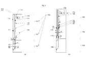
- FIG. 1 : Schematic representation of an automated cabinet having one fixed top panel, one intermediate movable panel, and one bottom movable panel, in closed cabinet modus
- (a) front view
- (b) inner view from the back
- FIG. 2 : Schematic representation of an automated cabinet having one fixed top panel, one intermediate movable panel, and one bottom movable panel, in open cabinet modus
- (a) front view
- (b) inner view from the back
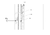
- FIG. 3 : Schematic representation of a guiding rail system of an automated cabinet having one fixed top panel, one intermediate movable panel, and one bottom movable panel
- (a) bottom movable panel in lower guiding zone
- (b) bottom movable panel in intermediate guiding zone
- FIG. 4 : Schematic representation of a hooked device coupled to an intermediate movable panel of an automated cabinet having one fixed top panel, one intermediate movable panel, and one bottom movable panel
- FIG. 5 : Schematic representation of a bottom movable panel, illustrating in front view the position of left upper and left lower wheels in the guiding rail system, of an automated cabinet having one fixed top panel, one intermediate movable panel, and one bottom movable panel, in closed cabinet modus
- FIG. 6 : Schematic representation of the theoretic velocity profile of two synchronized motors driving the two pulley systems respectively of a lifting system
- FIG. 7 : Schematic representation of a driving module coupled to a pulley system as part of a lifting system, of an automated cabinet having at least one fixed and at least one movable panel
- (a) inner view from the back
- (b) inner side view
- FIG. 8 : Schematic representation of a contact device
- (a) connected to the outer profile of upper mounting piece, enabling a movable panel to be raised or lowered, and hence opening or closing an automated cabinet having at least one fixed and at least one movable panel
- (b) disconnected to the outer profile of upper mounting piece, stop any movement of a movable panel, and hence no longer opening or closing an automated cabinet having at least one fixed and at least one movable panel
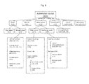
- FIG. 9 : Schematic overview of different components of an automated cabinet according to the present invention
DETAILED DESCRIPTION OF THE PREFERRED EMBODIMENTS
-
Before the present system and method of the invention are described, it is to be understood that this invention is not limited to particular systems and methods or combinations described, since such systems and methods and combinations may, of course, vary. It is also to be understood that the terminology used herein is not intended to be limiting, since the scope of the present invention will be limited only by the appended claims.
-
As used herein, the singular forms "a", "an", and "the" include both singular and plural referents unless the context clearly dictates otherwise.
-
The terms "comprising", "comprises" and "comprised of" as used herein are synonymous with "including", "includes" or "containing", "contains", and are inclusive or open-ended and do not exclude additional, non-recited members, elements or method steps. It will be appreciated that the terms "comprising", "comprises" and "comprised of" as used herein comprise the terms "consisting of", "consists" and "consists of".
-
The recitation of numerical ranges by endpoints includes all numbers and fractions subsumed within the respective ranges, as well as the recited endpoints.
-
The term "about" or "approximately" as used herein when referring to a measurable value such as a parameter, an amount, a temporal duration, and the like, is meant to encompass variations of +/-10% or less, preferably +/-5% or less, more preferably +/-1% or less, and still more preferably +/-0.1% or less of and from the specified value, insofar such variations are appropriate to perform in the disclosed invention. It is to be understood that the value to which the modifier "about" or "approximately" refers is itself also specifically, and preferably, disclosed.
-
Wherein the terms "one or more" or "at least one", such as one or more or at least one member(s) of a group of members, is clear per se, by means of further exemplification, the term encompasses inter alia a reference to any one of said members, or to any two or more of said members, such as, e.g., any ≥3, ≥4, ≥5, ≥6 or ≥7 etc. of said members, and up to all said members.
-
All references cited in the present specification are hereby incorporated by reference in their entirety. In particular, the teachings of all references herein specifically referred to are incorporated by reference.
-
Unless otherwise defined, all terms used in disclosing the invention, including technical and scientific terms, have the meaning as commonly understood by one of ordinary skill in the art to which this invention belongs. By means of further guidance, term definitions are included to better appreciate the teaching of the present invention.
-
In the following passages, different aspects of the invention are defined in more detail. Each aspect so defined may be combined with any other aspect or aspects unless clearly indicated to the contrary. In particular, any feature indicated as being preferred or advantageous may be combined with any other feature or features indicated as being preferred or advantageous.
-
Reference throughout this specification to "one embodiment" or "an embodiment" means that a particular feature, structure or characteristic described in connection with the embodiment is included in at least one embodiment of the present invention. Thus, appearances of the phrases "in one embodiment" or "in an embodiment" in various places throughout this specification are not necessarily all referring to the same embodiment, but may. Furthermore, the particular features, structures or characteristics may be combined in any suitable manner, as would be apparent to a person skilled in the art from this disclosure, in one or more embodiments. Furthermore, while some embodiments described herein include some but not other features included in other embodiments, combinations of features of different embodiments are meant to be within the scope of the invention, and form different embodiments, as would be understood by those in the art. For example, in the appended claims, any of the claimed embodiments can be used in any combination.
-
In the present description of the invention, reference is made to the accompanying drawings that form a part hereof, and in which are shown by way of illustration only of specific embodiments in which the invention may be practiced. Parenthesized or emboldened reference numerals affixed to respective elements merely exemplify the elements by way of example, with which it is not intended to limit the respective elements. It is to be understood that other embodiments may be utilised and structural or logical changes may be made without departing from the scope of the present invention. The following detailed description, therefore, is not to be taken in a limiting sense, and the scope of the present invention is defined by the appended claims.
-
According to a first aspect, the present invention relates to an automated cabinet (100), configured to switch between a closed cabinet modus and an open cabinet modus, the automated cabinet comprising:
- a plurality of panels (110), wherein the panels (110) partially or completely overlap in open cabinet modus, and wherein the panels (110) are co-planar in closed cabinet modus; and wherein the panels (110) comprise:
- ○ at least one fixed panel (112); and
- ○ at least one movable panel (113);
- two opposing sidewalls (120), perpendicular to the plurality of panels (110);
- a lifting system (130), coupled to the plurality of panels (110), wherein the lifting system (130) is configured to raise or lower one or more of the panels (110); and wherein the lifting system (130) comprises:
- ○ at least two pulley systems (134), coupled to the at least one movable panel (113), and configured to raise or lower the at least one movable panel (113) outside its centre of gravity; and
- ○ a guiding rail system (150), provided within the two opposing sidewalls (120), and configured to guide the at least one movable panel (113); and
- a driving module (140), operable to drive the lifting system (130);
wherein the guiding rail system (150) comprises at least one rail track (156) for each of the two opposing sidewalls and per movable panel (113), wherein the at least one rail track (156), or wherein each of the at least one rail track (156), for each of the two opposing sidewalls has an essentially constant rail track depth (157).
-
The at least one movable panel (113), being coupled to the at least two pulley systems (134), and being configured to raise or lower the at least one movable panel (113) outside its centre of gravity is herewith further explained. The at least one movable panel (113) is coupled to the at least two pulley systems (134) by means of at least two flexible members (136), i.e. one flexible member per pulley system being coupled to the movable panel. The point of application of the flexible member (136) for lifting the movable panel (113) is laying outside the centre of gravity of the movable panel (113), i.e. along the length of the flexible member (136) at a distance d from the movable panel (113), and at approximately the same horizontal level with respect to the ground surface as the centre of gravity location of the movable panel (113). As a consequence, a lifting force T on the flexible member (136) for lifting the movable panel (113) creates a moment of torsion Txd onto the movable panel (113).
-
A guiding rail system (150) being provided within the two opposing sidewalls (120), means that a rail track system including different rail tracks (156), and configured to guide the at least one movable panel (113) by means of its guiding wheels (116, 117, 118, 119) following a rail track (156) in upward or downward direction, is embedded in the inner cabinet surface of each of these two opposing sidewalls (120).
-
The at least one rail track (156) for each of the two opposing sidewalls (120) having an essentially constant rail track depth (157), is further clarified by the fact that the at least one rail track (156) for each of the opposing sidewalls (120) needs to have a constant depth, unless if a difference in rail track depth (157) would represent a specific functionality. In other words, the rail track depth (157) may vary only when there is a particular reason involved, beyond the mere guidance of the wheels moving upward or downwards. Quantitatively speaking, according to some embodiments of the present invention, deviations on the essentially constant rail track depth (157) of e.g. 1 mm are allowed in case of a 6mm rail track depth (157).
-
In some embodiments, the automated cabinet (100) of the present invention may further comprise a control module (160) configured to provide control instructions to raise or lower the at least one movable panel (113). Preferably, the control instructions are provided to the lifting system (130).
-
In some embodiments of the invention, a pulley system (134) may be provided on each of the two opposing sidewalls (120) of the cabinet (100), said pulley system comprising a flexible member (136) to raise or lower the at least one movable panel (113), and further comprising a rotor (138) driven by a driving module (140).
-
In some embodiments, the lifting system (130) of the automated cabinet (100) of the present invention can be driven at variable speed to raise or lower the at least one movable panel (113).
-
In some embodiments, the automated cabinet (100) according to present invention has a driving module (140) being a motor mounted in semi-flexible configuration, wherein said motor
- is coupled to a rotor (138) of a pulley system (134), along said rotor axis direction;
- is positioned against a mounting piece (137) that is coupled to an inner sidewall (120) surface, wherein said mounting piece comprises a contact device (148) for controlling the movement of the panels (110);
- is configured to move by tilting upwards or downwards around an axis parallel to said rotor axis direction and parallel to standing inner sidewall (120) surface.
-
A driving module (140) being a motor (142, 144) mounted in a semi-flexible configuration, in some embodiments according to present invention as indicated above, means that the motor (142, 144) is not assembled within the cabinet system (100) in an entirely fixed setup configuration. Hence, the motor (142, 144) may still partially move, however this partial movement or flexibility is limited by and only by the possibility for the motor of tilting upward or downward as compared to the ground surface. The motor (142, 144) tilting upwards or downwards around an axis parallel to the rotor axis direction may also tilt upwards or downwards around an axis coinciding with the rotor axis direction.
-
The contact device (148) mentioned above is configured to relatively change position with regard to the mounting piece (137) depending on the moving status of the panels (110). The contact device (148) is further configured to connect with the mounting piece (137) whenever the at least one movable panel (113) is raised anyhow or lowering without interruption, and is configured to disconnect with the mounting piece (137) whenever the at least one movable panel (113) is lowering and being stopped abruptly.
-
According to some embodiments, the driving module (140) of an automated cabinet (100) according to present invention comprises at least two motors (142,144), configured to drive the lifting system (130), and to directly drive each of the at least two pulley systems (134).
-
According to a second aspect, the present invention further encompasses a method for opening an automated cabinet (100), comprising steps of:
- (i) activating the control module (160), thereby driving the driving module (140),
- (ii) rotating the pulley wheel (139) of a pulley system (134), as part of a lifting system (130), in a certain direction,
- (iii) tightening a flexible member (136) coupled to the pulley wheel (139) and to an at least one movable panel (113),
- (iv) lifting at least one movable panel (113), guided via a guiding rail system (150). Preferably, the method according to the second aspect of the invention is for opening an automated cabinet (100) according to the first aspect of the invention, or a preferred embodiment thereof.
-
According to a third aspect, the invention further encompasses a method for closing an automated cabinet (100) according to descriptions above and below, is also part of the present invention, comprising steps of:
- (i) activating the control module (160), thereby driving the driving module (140),
- (ii) rotating the pulley wheel (139) of a pulley system (134), as part of a lifting system (130), in a certain direction,
- (iii) tightening a flexible member (136) coupled to the pulley wheel (139) and to an at least one movable panel (113),
- (iv) lowering the at least one movable panel (113), guided via a guiding rail system (150).
-
Preferably, the method according to the third aspect of the invention is for closing an automated cabinet (100) according to the first aspect of the invention, or a preferred embodiment thereof.
-
In additional aspects, a method for designing, assembling or building an automated cabinet (100) according to the first aspect of the invention, is provided by the present invention.
-
In preferred embodiments of the present invention and as illustrated in Fig. 1 and 2, an automated cabinet system (100) is provided, comprising a plurality of panels (110), i.e. one fixed top panel (112) and at least one additional movable panel (113), wherein the plurality of panels (110) partially or completely overlap in open cabinet modus, and wherein the plurality of panels (110) are co-planar in closed cabinet modus, i.e. the large panel surface (111) of all panels (110) appearing in front view seamlessly on top of each other along their horizontally positioned long length edges. Furthermore, the automated cabinet system comprises two opposing sidewalls (120), which are perpendicular to the plurality of panels and which are provided with a guiding rail system (150), configured to guide the movable panel(s) (113). The two opposing sidewalls (120) being perpendicular to the plurality of panels (110), includes although a range of e.g. 8% deviation from 90° perpendicularity, preferably perpendicular is interpreted within a range of 5% deviation from 90°. Moreover, the guiding rail system (150) comprises different guiding zones (152) having at least one rail track (156), wherein said at least one rail track (156) has an essentially constant rail track depth (157).
-
According to one embodiment of the present invention, the guiding rail system (150) comprises at least one rail track (156) for each of the two opposing sidewalls (120) and per movable panel (113), wherein the at least one rail track (156) for each of the two opposing sidewalls (120) has an essentially constant rail track depth (157). For example for an automated cabinet (100) having one movable panel (113), and thus one rail track (156) for each of the two opposing sidewalls (120), this one rail track having an essentially constant rail track depth (157). On the other hand, for an automated cabinet (100) having two movable panels (113), and hence two rail tracks (156) for each of the two opposing sidewalls (120), these rail tracks having an essentially constant rail track depth (157), having both the same rail track depth.
-
According to another embodiment of the present invention, the guiding rail system (150) comprises at least one rail track (156) for each of the two opposing sidewalls (120) and per movable panel (113), and wherein each at least one rail track (156) for each of the two opposing sidewalls (120) has an essentially constant rail track depth (157). For example for an automated cabinet (100) having one movable panel (113), and thus one rail track (156) for each of the two opposing sidewalls (120), this one rail track having an essentially constant rail track depth (157). On the other hand, for an automated cabinet (100) having two movable panels (113), and hence two rail tracks (156) for each of the two opposing sidewalls (120), each of these rail tracks having an essentially constant rail track depth (157), not necessarily having both the same rail track depth.
-
According to preferred embodiments of the present invention, the automated cabinet system (100) also comprises a driving module (140), operable to drive a lifting system (130), coupled to the movable panels (113), wherein said lifting system, comprising at least two pulley systems (134), is configured to raise or lower the present movable panels (113). More specifically, the pulley systems (134) are coupled to the movable panels (113), and are configured to raise or lower the movable panels (113) outside their centre of gravity. In other words, the point of application of the flexible member (136) for lifting the movable panel (113) is laying outside the centre of gravity of the movable panel (113), i.e. along the length of the flexible member (136) at a distance d from the movable panel (113), and at approximately the same horizontal level with respect to the ground surface as the centre of gravity location of the movable panel (113). Preferably, the pulley systems (134) are directly coupled to the bottom movable panel, being the lowest positioned movable panel in the automated cabinet configuration, and the pulley systems (134) are configured to directly raise or lower the bottom movable panel (113) outside its centre of gravity. An automated cabinet system (100) with reference to the present invention may be further provided with a control module (160), to direct control instructions to the driving module (140). Finally, the automated cabinet may be covered at the backside providing a back plate or rear wall (170).
-
Further, in some embodiments of the present invention, providing an automated cabinet system (100), there is no selectable access to open or close, i.e. raise or lower each of the panels individually. However, only movable panels can be lifted upwards or downwards in a fixed order, meaning the automated cabinet system is opened from bottom to top and closed from top to bottom. The movable panels are preferably meant to follow a predefined theoretic velocity profile curve, and hence are lifted at variable speed for opening and closing the automated cabinet. According to some embodiments of the present invention, while referring to the velocity profile curve, the movable panels are lifted for example at minimum at 15 mm/s and at maximum at 60 mm/s, preferably at minimum at 5 mm/s and at maximum at 75-80 mm/s, The automated cabinet is preferably further configured to open and close gradually, having at least one movable panel at the time raised or lowered, towards having only the fixed top panel left in front view for open cabinet modus (102), or else towards having a flat front plane composed of all panels stripped seamlessly on top of each other, hence appearing co-planar for closed cabinet modus (104).
-
In addition, in some embodiments of the present invention the automated cabinet system (100) comprises a driving module (140) composed of at least two motors (142, 144), for driving at least two corresponding pulley systems (134). More specifically, in embodiments of the present invention and also shown in Fig. 1 and 2, a lifting system (130) comprises two pulley systems, each provided with a rotor (138) via which each corresponding pulley system is driven by a respective motor (140). In other words, two pulley systems (134) are driven by two motors (142, 144) respectively via two corresponding rotors respectively. Providing an individual motor for each pulley system to be driven, operating synchronically, facilitates the mechanical construction of the cabinet, compared to using one single motor as driving module for a motorized lifting of cabinet panels. Furthermore, having two tilt-able motors (142, 144) in preferred embodiments of the present invention, the motors directly driving each a rotor connected to a corresponding pulley system, wholly or partially eliminates the use of a motor shaft born with both opposing sidewalls of the cabinet, and transmitting the driving force into a rotational movement of the motor shaft, being coupled to and thereby tightening a flexible member (136) as part of a pulley system (134).
Description of the components
-
Preferred embodiments of the present invention provide an automated cabinet system (100) comprising:
- a plurality of panels (110)
- two opposing sidewalls (120), provided with a guiding rail system (150)
- a lifting system (130), coupled to said plurality of panels (110)
- a driving module (140), operable to drive said lifting system (130)
- a control module (160), configured to provide control instructions for said driving module (140)
- optionally, a back plate or rear wall (170).
-
Each of these components and preferred embodiments thereof will now be described into detail below. Fig. 9 illustrates schematic overview of the different components of an automated cabinet according to the present invention.
-
In some embodiments of the present invention, the automated cabinet system (100) comprises a plurality of panels (110), wherein typically one panel is fixed (112) to the cabinet, and at least one movable panel (113) is provided. Furthermore, for preferred embodiments of the present invention and as shown in Figures 1, 2 and 5, all panels are generally positioned, such that the large panel surface (111) of the panels is placed in vertical position and all large panel surfaces (111) appear seamlessly stripped on top of each other along their long length edges, as one plane surface representing the front view of the automated cabinet system, and hereinafter referred to as co-planar, whenever the automated cabinet is in closed cabinet modus (104).
-
Preferred embodiments of the present invention comprise a panel (112) at the front of the automated cabinet system, said panel (112) being in a fixed position in the upper or top area of the front surface of the cabinet, illustrated in Figures 1, 2 and 5. According to some embodiments of the present invention and shown in Figures 2 and 5, the fixed top panel (112) is co-planar with the other movable panels (113) whenever the automated cabinet system is in closed cabinet modus (104). In open cabinet modus (102), illustrated by Fig. 1, said fixed top panel is the only visible panel in front view of the automated cabinet system. Moreover, when the automated cabinet system is fully opened, all movable panels (113) are hidden one behind the other behind the fixed top panel (112) in the inner top area of the cabinet. For the automated cabinet system in closed cabinet modus, all panels (100), i.e. fixed (112) and movable panels (113), being co-planar almost seamlessly cover the front of the automated cabinet system (100), as shown in Fig. 2.
-
Some embodiments of the present invention further comprise at least one panel (113), which is movable in order to change the automated cabinet system from open to closed cabinet modus or vice versa. The movable panel(s) (113) may be provided with guiding wheels (116, 117, 118, 119) in order to facilitate the movement of said movable panel(s) (113) upwards for opening, or either downwards for closing the automated cabinet system (100). Moreover, the guiding wheels may be coupled to the movable panel(s) (113), using a wheel mounting piece (131) for each guiding wheel. A wheel mounting piece (131) is fixed onto the backside of a movable panel (113), close to its vertical edges (114, 115) respectively coupled to one of the two opposing sidewalls (120).
-
In some embodiments of the present invention, there are guiding wheels (116, 117, 118, 119) fixed onto two opposing edges (114, 115) of the movable panels (113). Considering the position of the movable panels as illustrated in Figures 1, 2 and 5, the movable panels (113) are provided with guiding wheels on the left vertical edge (114), as well on the opposing right vertical edge (115) of the movable panels (113). According to some embodiments of the present invention and supported by Figures 1, 2 and 3, there are four guiding wheels coupled to each movable panel (113) via a wheel mounting piece (131), i.e. two guiding wheels coupled to the left vertical edge (114) of the movable panel (113) using two respective wheel mounting pieces (131), and two guiding wheels coupled to the right vertical edge (115) of the movable panel (113) using another two respective wheel mounting pieces (131). The two guiding wheels coupled to each of the vertical edges (114, 115), are positioned at a relatively large distance from each other, i.e. one of the two guiding wheels is coupled to the vertical edge close to the top of the movable panel (113), being the left or right upper wheel (116, 118), wherein the other of the two guiding wheels is coupled to the vertical edge close to the bottom of the movable panel (113), being the left or right lower wheel (117, 119).
-
In some embodiments of the present invention, the four guiding wheels fixed onto each movable panel, are typically made of steel or metal, however hard plastic or composite or synthetic material may also be used, as long as the finished surface is fit for the guiding rail application. In some embodiments the guiding wheels have a width of at least 2mm and at most 25mm, for example at least 2 mm and at most 10mm, for example at least 3mm and at most 6mm, preferably at least 4mm and at most 5mm. Further, in some embodiments the guiding wheels have a radius of at least 1.5mm and at most 10mm, for example at least 2 mm and at most 8mm, for example at least 3mm and at most 6mm, preferably at least 4mm and at most 5mm. In preferred embodiments of the present invention, the upper and lower wheels are equal, having the same size or measures. Moreover, said guiding wheels preferably have a specific surface roughness to optimally guide said movable panel concerning e.g. friction and wear, during lifting. In certain embodiments of present invention, wherein a guiding rail system (150) is provided via which the guiding wheels are moved during panel lifting, and wherein said guiding rail system comprises a rail track (156) typically made of wood, preferably hard wood, hard plastics, HPL (high pressure laminate), hard laminate, aluminium or steel, with rail track width (158) of at least 3mm and at most 20mm, for example at least 4 mm and at most 15mm, for example at least 6mm and at most 12mm, preferably at least 9mm and at most 10mm and having a rail track depth (157) of at least 2mm and at most 30mm, for example at least 3 mm and at most 20mm, for example at least 4mm and at most 10mm, preferably at least 5mm and at most 7mm, wherein the guiding wheels preferably have a flat surface.
-
Furthermore, for some embodiments of present invention, the four guiding wheels (116, 117, 118, 119) coupled to the movable panel (113) guide each movable panel when raised or lowered via the guiding rail system (150) having a certain rail track depth (157) and rail track shape, as further described below.
-
For preferred embodiments of the present invention, wherein at least two movable panels (113) are present, as illustrated in Figures 1, 2 and 3, the lowest positioned movable panel is called the bottom movable panel, wherein a movable panel positioned between the bottom movable panel and the fixed top panel, is called hereinafter an intermediate movable panel. Further supported by Figures 1, 2 and 3, each intermediate movable panel comprises a hooked device (132) on top of said intermediate movable panel. A backside of an intermediate movable panel is defined as the inner cabinet surface side of the intermediate movable panel. More specifically with respect to the hooked device and as shown in Figures 1, 2 and 3, this hooked device (132) is fixed on the left upper and on the right upper area of the backside of an intermediate movable panel, such that a right angle hook at the top edge of the intermediate movable panel characterizes the hooked device. Furthermore, part of the hooked device (132) is positioned perpendicularly to the vertically standing large panel surface (111) of the intermediated movable panel, and defined herein as the horizontal part of the hooked device. The hooked devices (132) are typically curved or bended, rod or plate shaped, wherein the horizontal part of these hooked devices (132) in some embodiments may have a length of at least 30mm and at most 250mm, for example at least 30mm and at most 100mm, for example at least 35mm and at most 75mm, preferably at least 40mm and at most 60mm in case of an automated cabinet comprising one fixed and two movable panels. As depicted in Figures 3 and 4, with the horizontal part of the hooked devices (132), the intermediate movable panel is lifted upwards or raised, out of closed panel modus, as said horizontal part being supported by a lower intermediate movable panel whenever present, or by the bottom movable panel. In summary, the hooked devices (132) are provided and configured to assist in lifting or guiding the intermediate movable panels towards the required position. Moreover, the hooked devices (132) are designed and fixed in a way to bring the corresponding intermediate movable panel, onto which the hooked devices are attached, outside its centre of gravity. The intermediate panel is lifted-up by the hooked device, such that the point of application of the lifting force is laying outside but horizontally - as compared to the ground surface - at approximately the same level or height of the centre of gravity of the intermediate panel.
-
Further, in some embodiments of the present invention, wherein at least two movable panels (113) are present, as illustrated in Figures 1 and 2, the bottom movable panel comprises a protection device (133) on top of said bottom movable panel. The backside of the bottom movable panel is defined as the inner cabinet surface side of said bottom movable panel. More specifically with respect to the protection device (133) and as shown in Figures 1, 2 and 3, said protection device is fixed on the left upper and on the right upper area of the backside of the bottom movable panel, and possibly covering small part of the top edge of the bottom movable panel, such that said protection device (133) is coupled to the hooked device (132) of the intermediate movable panel, this hooked device (132) as described in the previous paragraph, whenever the bottom movable panel is supporting the intermediate movable panel when the intermediate movable panel is raised or lowered. The protection devices (133) are typically square clip shaped, made of plastic, polymer-type, synthetic or composite material, with length-width-thickness measures for example of at least 10mm x 10mm x 1mm and at most 100mm x 125mm x 30mm, preferably of at least 40mm x 40mm x 6mm and at most 80mm x 80mm x 16mm, for hooked devices (132) according to the description above, and are mounted onto the bottom movable panel in order to protect top edge of the bottom movable panel against wear, whenever picking up the intermediate movable panel during lifting.
-
In some embodiments of the present invention, as shown in Figures 1 and 2, the bottom movable panel further comprises a mounting piece, referred to herein as bottom mounting piece (135), fixed respectively onto the lower left and onto the lower right of the backside surface of said bottom movable panel, whereby the bottom mounting piece (135) is part of a pulley system (134) in order to lift said bottom movable panel. More specifically, each bottom mounting piece (135) is coupled with a flexible member (136) provided by the pulley system (134) to raise or lower the bottom movable panel, in such a manner that this flexible member (136) is pending vertically along its length at a distance d from the bottom movable panel. Both flexible members (136), left and right coupled to the bottom movable panel via bottom mounting piece (135), pull the bottom movable panel with force T, creating a moment Txd. This moment Txd results in two forces Fb and Fo, illustrated in Figure 3. The force Fb pushes the upper area of the bottom movable panel towards the front of the cabinet, while the force Fo pushes the bottom movable panel towards the back of the cabinet, or more inward the cabinet. Consequently, the upper wheels (116, 118) of the bottom movable panel are pushed against the front cabinet side of the guiding trail track (157), wherein the lower wheels (117, 119) of the bottom movable panel are pushed against the back or inner cabinet side of the guiding rail track (157).
-
Finally, according to some embodiments of the present invention, at a certain height reached by the bottom movable panel being pulled by both flexible members (136), the top edge of said bottom movable panel is coupled to a hooked device (132) fixed onto an intermediate movable panel, such that, when now further guiding the bottom movable panel upwards, said bottom movable panel picks up and supports the intermediate movable panel. The bottom movable panel delivers a force D onto both hooked devices (132) fixed respectively left and right onto the intermediate movable panel, such that a moment Dxd is generated. The moment Dxd results in two forces Fb and Fo. The force Fb pushes the upper area of the intermediate movable panel towards the front of the cabinet, while the force Fo pushes the intermediate movable panel towards the back of the cabinet, or more inward the cabinet. Consequently, and similarly as described above for the guiding wheels of the bottom movable panel, the upper wheels (116, 118) of the intermediate movable panel are pushed against the front cabinet side of the guiding trail track, wherein the lower wheels (117, 119) of the intermediate movable panel are pushed against the back or inner cabinet side of the guiding rail track.
-
In some preferred embodiments of the present invention, an automated cabinet system (100) comprises two opposing sidewalls (120), perpendicular to the panels (110).
-
Furthermore, according to preferred embodiments of the present invention, the two opposing sidewalls (120) are provided with a guiding rail system (150). As illustrated by the cabinet inner side view of Fig. 3, the guiding rail system provided in the inner cabinet side of each of the two opposing sidewalls, has different guiding zones (152) and at least one rail track (156) for guiding at least one movable panel (113).
-
Additionally, in some preferred embodiments of the present invention, provided with a guiding rail system (150) comprising different guiding zones (152), the number of different guiding zones equals the total number of panels, meaning fixed panel (112) and all movable panels (113). As an example and according to Figures 1, 2 and 3, where the automated cabinet system comprises one fixed panel and two movable panels, the total number of panels equals three. Hence, there are three guiding zones identified, as indicated in Fig. 3, one upper guiding zone (153), one intermediate guiding zone (154), and one lower guiding zone (155). Moreover, for each guiding zone (152), there is at least one rail track (156) present for each of the two opposing sidewalls, preferably at least two for each of the two opposing sidewalls, whereas one of the preferred embodiments comprises two movable panels and one fixed panel.
-
For each movable panel (113) in embodiments of the present invention, there is an individual rail track (156) to be followed, as also shown in Fig. 3. In other words, each movable panel (113) has its own rail track to be guided when lifted upwards or downwards in the automated cabinet system. Consequently, each guiding zone (152) comprises at least one rail track (156) for a corresponding movable panel (113) to be guided.
-
A rail track (156) of a guiding rail system (152) for embodiments of the present invention is typically made of wood, preferably hard wood, hard plastics, HPL (high pressure laminate), hard laminate, aluminium or steel, in order to generate optimal movement and friction. Preferably, the rail track minimises wear on the guiding wheels (116, 117, 118, 119) made of steel or metal, hard plastic or a particular composite or synthetic material, as well as for the rail track (156) via which the guiding wheels are moving.
-
Further, according to embodiments of the present invention, each rail track (156) present in each of the guiding zones (152) has a constant rail track depth (157) within said guiding zone. Using a constant rail track depth (157) along the entire rail track length causes a better stability and balanced guidance of the panels, compared to using different rail track depths (157) for each of the guiding zones (152).
-
Moreover, a rail track depth (157) is preferably at least 2mm and at most 30mm, for example at least 3 mm and at most 20mm, for example at least 4mm and at most 10mm, preferably at least 5mm and at most 7mm. The guiding wheels in some embodiments have a width of at least 2mm and at most 25mm, for example at least 2 mm and at most 10mm, for example at least 3mm and at most 6mm, preferably at least 4mm and at most 5mm, and have a radius of at least 1.5mm and at most 10mm, for example at least 2 mm and at most 8mm, for example at least 3mm and at most 6mm, preferably at least 4mm and at most 5mm. The panels (110) preferably have dimensions of at least 200mm x 100mm x 10mm, for example at least 500mm x 250mm x 25mm, for example at least 1000mm x 500mm x 40mm.
-
As a preferred shape of a rail track (156) in embodiments of the present invention, the following configuration is described and illustrated in Fig. 3. In the design as presented a rail track (156) is configured as one straight vertical rail track line having at least one side track part for guiding corresponding movable panel (113) from open to closed panel modus position or vice versa.
-
According to a preferred embodiment of the present invention as illustrated in Fig. 3, representing an automated cabinet comprising one fixed panel (112) and two movable panels (113), the upper guiding zone (153) comprises two rail tracks (156), i.e. one rail track for the intermediate movable panel to be guided and one rail track for the bottom movable panel to be guided. Both of said two rail tracks (156) are represented as straight vertical rail track lines in the upper guiding zone (153). Also depicted in Fig. 3 is the intermediate guiding zone (154), again having two rail tracks (156) for each of the respective movable panels to be guided, however the intermediate guiding zone now representing the rail track for the intermediate movable panel to be guided, as two short diagonal side track parts and a straight vertical rail track part in between, coupling said short diagonal side track parts, in order to bring the intermediate movable panel as moving downwards into closed panel modus position. The other remaining rail track for the bottom movable panel to be guided, within the intermediate guiding zone, is still in the configuration of a straight vertical rail track line. Further shown in Fig. 3 is the lower guiding zone (155), having only one rail track (156) left, depicted as two short diagonal side track parts and a straight vertical rail track part in between, coupling said short diagonal side track parts, in order to bring the bottom movable panel into closed panel modus position, and concurrently arriving at closed cabinet modus position (104), whenever guided downwards.
-
With respect to preferred embodiments of the present invention, the left and right upper wheels (116, 118) coupled to the movable panels (113), roll deeply within the rail track (156) of the guiding rail system (150), i.e. the upper guiding wheels roll with their full width entirely within the full depth of the rail track, whereas the left and right lower wheels (117, 119) are moving closer to the sidewall edge surface of the guiding rail system. In fact, the lower guiding wheels (117, 119) are not moving at full depth within the rail track (156), but are following the rail track (156) closer to the inner cabinet surface of the sidewall (120).
-
Moreover, according to embodiments of the present invention, due to the configuration of the movable panel outside its centre of gravity, the upper guiding wheels (116, 118) roll against the front edge, i.e. the edge closest to the front of the cabinet, of the vertical track part or against the upper edge of the diagonal side track part, while the lower guiding wheels (117, 119) roll against the rear edge, i.e. the edge closest to the rear of the cabinet, of the vertical track part or against the lower edge of the diagonal side track part. As a result the rail track design may be amended by replacing the two diagonal side tracks within the same guiding zone (152) by one large side track surface at rail track depth while bringing the inner sidewall surface area between the upper diagonal side track and the lower diagonal side track within the same guiding zone (152) to track depth level. Due to the fact that open space at track depth level without track edges interrupting, is now present between the upper and the lower edge of the new large side track surface, while this open space being present in the front area of the automated cabinet system (100), a security system is provided, leaving enough space and freedom of movement in the front area to easily push or pull the movable panel (113) whenever an object got stuck somewhere in the movable panel area.
-
Finally, in some embodiments of the present invention, the two opposing sidewalls (120) are coupled both respectively with a pulley system (134) as part of a lifting system (130). The coupling between a sidewall and a pulley system is enabled using a mounting piece, hereafter referred to as an upper mounting piece (137), fixed onto the inner upper area of respectively each of the two opposing sidewalls (120), whereby the upper mounting piece (137) forms part of said pulley system (134). Moreover, the upper mounting piece (137), comprising an outer profile (146) and an inner profile (147), is further coupled to a rotor (138), being coupled to a flexible member (136), wherein rotor and flexible member are also part of the pulley system (134), designed to raise or lower a movable panel (113). Finally, onto the inner profile (147) of the upper mounting piece (137) a contact device (148) is assembled, wherein this contact device when connected to the outer profile of upper mounting piece (146), may enable a movable panel (113) to be raised or lowered, and hence open or close the automated cabinet.
-
In preferred embodiments of the present invention, an automated cabinet system (100) comprises a lifting system (130) to raise or lower at least one movable panel (113), said lifting system being provided with at least two pulley systems (134), coupled to the bottom movable panel by a bottom mounting piece (135), and wherein said pulley system (134) is configured to raise or lower said bottom movable panel outside its centre of gravity. Hence, the point of application of the flexible member (136) for lifting the bottom movable panel (113) is laying outside the centre of gravity of the bottom movable panel (113), i.e. along the length of the flexible member (136) at a distance d from the bottom movable panel (113), and at approximately the same horizontal level with respect to the ground surface as the centre of gravity location of the bottom movable panel (113). Furthermore, the lifting system (130) for an automated cabinet system (100), according to preferred embodiments of the present invention, is coupled to a guiding rail system (150), said guiding rail system being provided within two opposing sidewalls (120), and configured to guide at least one panel (113) when lifted upwards or downwards.
-
Furthermore, in some embodiments of the present invention, wherein the lifting system (130) is provided with at least two pulley systems (134), each pulley system comprises a flexible member (136), coupling a bottom mounting piece (135) via a rotor (138) with an upper mounting piece (137). Hence, each pulley system (134) of a lifting system (130) is coupled on one hand to the inner upper area one of the two opposing sidewalls (120) by an upper mounting piece (137), while on the other hand each pulley system (134), and thus lifting system (130), is coupled to the inner lower area of the bottom movable panel by a bottom mounting piece (135) in order to lift the bottom movable panel upwards or downwards according to control instructions given by the control module (160). Moreover, each pulley system of said lifting system comprising a rotor (138), is driven by a driving module (140), wherein said driving module may be a small DC-motor.
-
Considering an automated cabinet according to some embodiments of the present invention, having a lifting system (130) comprising two pulley systems (134), each of these two pulley systems is coupled to a small DC-motor (142, 144). Hence, the lifting system when operating uses two synchronized motors, instead of just one large centrally positioned asynchronic motor as can be referred to in the prior-art, in order to open or close the automated cabinet.
-
For some embodiments of the present invention and referring to Figures 1, 2 and 7, comprising a pulley system of a lifting system comprising an upper mounting piece (137), coupling a flexible member (136) via a rotor (138) to inner upper area of a sidewall (120), said upper mounting piece comprises an outer profile (146) and an inner profile (147). Moreover, the outer profile of upper mounting piece is fixed close to the top edge of a sidewall (120), by a plate-shaped first part coupled to an open cubical shaped second part. The open cubical shaped second part of the outer profile is coupled to a flexible member (136) and a driving module via a rotor (138). Further, the open cubical shaped second part of the outer profile encloses the inner profile (147) of upper mounting piece, also coupled to flexible member (136) and driving module (140) via the rotor (138), and whereby the inner profile (147) is similarly but a little smaller, for example at least 1% and at most 20% smaller, open cubical shaped compared to the open cubical second part of the outer profile (146). In addition, onto the inner profile (147) of upper mounting piece a contact device (148) is assembled, wherein this contact device when connected to the outer profile (146) of upper mounting piece, will enable a movable panel (113) to be raised or lowered, and hence open or close the automated cabinet. The upper mounting piece (137) is typically made of steel or metal, having e.g. an outer profile (146) with plate shaped first part length-height dimensions of at least 20mm x 20mm, for example at least 100mm x 100mm, for example at least 150mm x 150mm, whenever an automated cabinet system (100) is considered according to the present invention, comprising panels (110) of at least 200mm x 100mm x 10mm, for example at least 500mm x 250mm x 25mm, for example at least 1000mm x 500mm x 40mm.
-
For embodiments of the present invention, as illustrated in Fig. 1, 2 and 7, the upper mounting piece (137) is coupled to a rotor (138), wherein said rotor is coupled to a flexible member (136), both being also part of the pulley system (134), designed to raise or lower a movable panel (113). The coupling between a rotor (138) and a flexible member (136) is enabled by a pulley wheel (139), onto which the flexible member is tightened, whenever the bottom movable panel is raised or lowered. The rotor (138) is further coupled to a driving module (140), for driving the pulley system (134), raising or lowering directly the bottom movable panel by its flexible member (136), and eventually having also other movable panels lifted.
-
Additionally, some embodiments of the present invention, having a pulley system (134) for a lifting system (130) comprising a rotor (138), said rotor has its axis of rotation positioned perpendicular to each of two opposing sidewalls (120), and hence the axis position being parallel to all fixed (112) and movable panels (113) of the automated cabinet system considered. Whenever a pulley system (134) operates and thus the rotor (138) rotates, a pulley wheel (139) is rotated as being coupled to the rotor. While the pulley wheel (139) rotates, a flexible member (136) coupled to said pulley wheel is tightened, and as a consequence the bottom movable panel is raised or lowered, depending on the direction of rotation of the rotor, hence depending on the direction of rotation of the pulley wheel and finally depending on the tightening direction of the flexible member.
-
With reference to Figures 1, 2 and 7, in some embodiments of the present invention, a pulley system (134) of a lifting system (130) further comprising a bottom mounting piece (135), coupling a flexible member (136) with the bottom movable panel, said bottom mounting piece is fixed respectively onto the lower left and onto the lower right of the backside surface of said bottom movable panel, in order to lift the bottom movable panel. The coupling of a flexible member (136) with a bottom mounting piece (135) is configured in a way such that the bottom movable panel is brought outside its centre of gravity whenever lifted, while the vertical edges (114, 115) of said bottom movable panel, positioned parallel to each of the two opposing sidewalls (120), are standing almost perpendicular to the ground surface of the cabinet (100). Again, the point of application of the flexible member (136) for lifting the bottom movable panel (113) is laying outside the centre of gravity of the bottom movable panel (113), i.e. along the length of the flexible member (136) at a distance d from the bottom movable panel (113), and at approximately the same horizontal level with respect to the ground surface as the centre of gravity location of the bottom movable panel (113). Hence, the weight of said bottom movable panel is slightly leaning forward in the front surface area, perfectly guiding said bottom movable panel, as well as keeping said bottom movable panel in balanced and required position, with top and bottom horizontally positioned long length edges of said movable panel remaining parallel to the ground surface of the cabinet (100), representing a stable mechanical construction whenever said movable panel is raised or lowered.
-
In case of intermediate movable panels occurring in some preferred embodiments of the present invention, these intermediate movable panels are balanced, guided and lifted similarly as compared to the bottom movable panel, i.e. by bringing said intermediate movable panels outside their centre of gravity and by keeping said intermediate movable panels in required individual position of having the large panel surface of the panels vertically positioned, and as proceeding from lifting the bottom movable panel towards including lifting the intermediate movable panels, thereby using supportively for a good panel guidance the hooked devices (132) fixed on top of the intermediate movable panels.
-
In embodiments of the present invention, having a pulley system (134) of a lifting system (130) comprising a bottom mounting piece (135), said bottom mounting piece is typically rectangular plate shaped provided with a hole or clip system and tightening buttons for coupling a flexible member (136), this bottom mounting piece being made of plastic, polymer-type, synthetic or composite material, aluminium or steel and having length-width-thickness measures of at least 3mm x 3mm x 0,5mm, for example at least 10mm x 10mm x 1 mm, for example at least 20mm x 20mm x 2mm, whenever an automated cabinet system (100) is considered according to the present invention, comprising panels (110) of at least 200mm x 100mm x 10mm, for example at least 500mm x 250mm x 25mm, for example at least 1000mm x 500mm x 40mm.
-
Further, according to some embodiments of the present invention, a flexible member (136), e.g. a belt as used for car child seats, as part of a pulley system, is preferably made of nylon or any other synthetic or natural material, representing comparable tensile strength. These flexible members (136) preferably have a thickness in the range of from 0.50mm to 2mm, preferably between 0.80mm and 1.5mm, and have a width for example of at least 10mm, preferably between 30mm and 60mm, in order to have good strength, optimal friction and sufficient wear resistance, wherein the length used depends on and is comparable with the automated cabinet height. Smaller or thinner flexible members can be maintained to further compact the cabinet construction, or e.g. whenever lighter panels are used.
-
According to some embodiments of the present invention, the at least two pulley systems (134) instead of being coupled to the inner upper area of the sidewall (120), may also be coupled to upper inner area of the back plate or rear wall (170).
-
In preferred embodiments of the present invention, the automated cabinet system (100) comprises a driving module (140), for driving a pulley system (134) of a lifting system (130) in order to raise or lower a plurality of movable panels (113). Furthermore, the driving module may be coupled to a rotor (138) being part of the pulley system, wherein said rotor rotates as soon as said driving module is transferring energy towards said rotor, and hence a rotational force is generated by said rotor. Depending on control instructions given to a driving module, said driving module will generate a rotation of said rotor in a certain predetermined direction, which in turn will lead to either raising or lowering at least one movable panel (113) due to the rotation of a pulley wheel (139), also provided by the pulley system, wherein said pulley wheel is coupled to the rotor as well as being coupled to at least one movable panel (113) via a flexible member (136).
-
According to some embodiments of the present invention, and as illustrated in Figures 7 and 8, a driving module (140) for driving a lifting system (130), is a motor (142, 144) being mounted in semi-flexible configuration, wherein said motor is coupled to a rotor (138) of a pulley system (134), along said rotor axis direction. Moreover, said motor is positioned against the outer profile (146) of an upper mounting piece (137) that is coupled to an inner sidewall (120) surface, wherein the inner profile (147) of said mounting piece (146) comprises a contact device (148). Furthermore, said motor can move by tilting upwards or downwards around an axis parallel to the rotor axis direction and parallel to vertically positioned inner sidewall (120) standing surfaces, wherein an upward tilt is determined by the movable panel being raised or lowered regularly in a standard usual way, without any obstruction occurring and thereby bringing the panels out of balance. As illustrated in Fig. 8a, the flexible member (136) is now tightened straight, and the contact device coupled to the inner profile (147) is connected with the outer profile (146) of the upper mounting piece, indicating that the movable panel can be further guided upward or downward. Further depicted in Fig. 8b, whenever the movable panel (113) is lowered and stopped, due to arriving in final closed modus position, or because of being hindered or out of balance, the flexible member (136) will loose tightness and thereby tilt the motor downwards. As the tilting position of the motor (142, 144) is coupled to the inner profile (147) of the mounting piece, the inner profile will hence also move towards another position, thereby disconnecting the contact device (148) coupled to the inner profile (147) from the outer profile (146) of the upper mounting piece (137), and hence the motor is automatically stopped.
-
When mounting or assembling the motor (142, 144) in a tiltable way, the mechanical construction thereby configured compensates for possible unbalance, which otherwise may occur while lifting or guiding a movable panel (113). Hence, having a so-called tiltable motor installed, generates a stable and balanced design operation.
-
Further, in some embodiments of the present invention, provided with a driving module (140), such as a motor (142, 144), in order to drive a pulley system (134) of a lifting system (130) for raising or lowering movable panels (113), said driving module is configured to drive the pulley system at variable speed, attempting to follow a specific theoretic velocity profile curve.
-
In some embodiments of the present invention, using at least two pulley systems (134), requires said pulley systems to operate synchronically at the same pace. Therefore, having a lifting system (130) with two pulley systems as depicted in Figures 1, 2 and 5, the two motors (142, 144) coupled to each of the two pulley systems respectively in order to drive the lifting system, are synchronized and controlled to follow both the theoretic velocity profile as illustrated in Fig. 6. The two motors (142, 144) accelerate when just activated from closed cabinet modus (104), until a maximum velocity is reached and controlled at a constant level further lifting the respective movable panel (113). The movable panel arrives at this constant maximum velocity when the upper guiding wheels (116, 118) have reached vertically aligned rail track part of corresponding rail track (156), and hence will now only move the panel in upward direction, after having been guided inward the cabinet and raised simultaneously. Whenever this movable panel reaches a position close to where another movable panel is picked up, the two motors (142, 144) will slow down to a lower velocity, reaching a minimum when both movable panels (113) are perfectly parallel positioned one after the other at the same height. Following, the two motors accelerate again the moment said other movable panel is picked up, until the maximum velocity is reached again and kept at a constant level whenever the upper guiding wheels (116, 118) of the movable panels (113) have reached a new guiding zone. In a similar way, vice versa, the velocity of the two motors is controlled and evolves over time, when activating the lifting system from open cabinet modus (102), whereby the two motors are driving synchronically said lifting system (130) in order to lower the movable panels (113) towards closed modus.
-
Finally, the two synchronized motors (142, 144) according to preferred embodiments of the present invention are controlled to follow the theoretic velocity profile as depicted in Fig. 6, using a programmed PID controller. The moment that the position of the motors deviates from the theoretic curve, this position being registered will be adjusted by comparison with the theoretical target position. For example, every 5 to 40 milliseconds such a comparison is performed, and the situation is controlled to have the least possible deviation at any time. However, whenever the deviation becomes too large and has reached a certain maximum, the motors will be stopped automatically. The synchronization of both motors is forced by aiming at minimum deviation of the position of the motors compared to the theoretic velocity profile curve.
-
In preferred embodiments of the present invention, the automated cabinet system (100) comprises a control module (160), configured to provide control instructions to a driving module (140) in order to lift one or more movable panels (113), preferably all movable panels (113) upwards or downwards.
-
According to some embodiments of the present invention, a control module (160) provided to give control instructions to a driving module (140) to operate a lifting system (130) to raise or to lower at least one movable panel (113), comprises at least two buttons, i.e. one button when activated giving instructions to raise said at least one movable panel (113), and one button when activated giving instructions to lower said at least one movable panel (113). Moreover, for some embodiments of the present invention, the control module can be activated by remote control comprising at least two buttons to transmit instructions to the driving module (140).
-
Further, in some embodiments of present invention, whenever pushing the closing button a first time, the appropriate movable panel (113) will be lowered downward until in its final closed modus, or until said closing button is pushed a second time. Pushing the closing button once more after a second push will activate the closing process again. Similarly, whenever pushing the opening button a first time, the appropriate movable panel (113) will be raised upward until in its final open modus, or until said opening button is pushed a second time. Pushing the opening button once more after second push will activate the opening process again. In other words, there is not necessarily an additional stop button present for stopping the automated cabinet from its opening or closing action. To stop the movable panels (113) from moving, can simply be activated by further pushing of the opening or closing button.
-
In some embodiments of the present invention, the automated cabinet system (100) comprises a back plate or rear wall (170), covering the backside of the cabinet.
-
Embodiments of the present invention may comprise a back plate or rear wall (170) at the back of the automated cabinet system (100), as illustrated in Fig. 1. According to some embodiments of the present invention and shown in Fig. 1, the back plate or rear wall (170) has its large surface plate positioned parallel with the plurality of panels (110) present.
-
Further, in preferred embodiments of the present invention, the back plate or rear wall (170) may be coupled to a pulley system (134) being part of a lifting system (130). The coupling between a rear wall and a pulley system may be enabled using a mounting piece, an upper mounting piece (137), fixed respectively left and right onto the inner upper area surface of said rear wall (170), whereby said upper mounting piece is part of said pulley system. Moreover, said upper mounting piece is further coupled to a rotor (138), being coupled to a flexible member (136), wherein rotor and flexible member are also part of the pulley system, designed to raise or lower at least one movable panel (113).
-
In embodiments of the present invention while referring to Figures 1 and 2, the process for opening an automated cabinet system according to the first aspect of the invention from closed modus towards open modus is described as follows.
-
Whenever initiating the opening process of an automated cabinet system in closed modus by pushing the respective button of the control module, all panels, i.e. one fixed top panel and at least one movable panel, are co-planar and viewed from the front as stripped plane surfaces one on top of the other, such that the planes seamlessly connect with their long edges. Opening the closed cabinet can be controlled manually or remotely, by giving instructions via a control module. Whenever instructions are activated to open the cabinet, i.e. the respective button of the control module is pushed, a driving module will start to drive a pulley system of a lifting system, such that a rotor provided by said pulley system and coupled to a flexible member via a pulley wheel, will start rotating in a certain predetermined direction, thereby tightening said flexible member in this particular direction such that the bottom movable panel which is coupled to the flexible member is lifted upwards. When the bottom movable panel is raised, said bottom movable panel is guided upwards using a guiding rail system, and thereby moves the bottom movable panel via a rail track towards a parallel position more inwards of the cabinet until the end of a first guiding zone, as part of the guiding rail system, is reached. Hence, for this first rail track part within the first guiding zone, the bottom movable panel is raised and guided inwards simultaneously.
-
Preferred embodiments for multiple cabinet configurations, each comprising a different amount of panels, are further considered below, when leaving the first guiding zone.
Situation 1: Opening an automated cabinet system comprising one fixed top panel and two movable panels, i.e. one intermediate movable panel and one bottom movable panel
-
Leaving the first guiding zone, a second guiding zone is reached by the upper wheels of the bottom movable panel and further raised as long as instructions are submitted to continue opening the cabinet. Within said second guiding zone, the bottom movable panel is now only guided via its corresponding rail track vertically in upward direction, thereby further gradually opening the cabinet. At a certain height reached by the bottom movable panel, the protection device at top edge of said bottom movable panel is coupled to a hooked device fixed onto an intermediate movable panel, such that, when now further guiding the bottom movable panel upwards, said bottom movable panel picks up and supports the intermediate movable panel, also lifted using the guiding rail system, however being guided via a separate rail track compared to the bottom movable panel. At first the intermediate movable panel is now also guided upwards, and thereby moving said intermediate movable panel via corresponding rail track towards a parallel position more inwards of the cabinet, whereby this corresponding rail track is configured closer to the front of the cabinet compared to the rail track designed for the bottom movable panel. More specifically, the rail track of the intermediate movable panel is configured at the inner surface of a sidewall, and located between the rail track of the bottom movable panel and the front side of the cabinet (of which the top fixed panel is always part of). Within the second guiding zone the upper (and lower) wheels of the intermediate movable panel move upwards such that the intermediate movable panel is raised and guided inwards simultaneously, while the upper (and lower) wheels of the bottom movable panel are only further moving upwards the bottom movable panel via its vertical rail track part. The upper wheels of the movable panels, when leaving the second guiding zone, reach a third guiding zone wherein these upper wheels of both the bottom movable panel and the intermediate movable panel further move upwards, thereby raising the movable panels, as long as instructions are submitted to continue opening the cabinet. Within said third guiding zone, both movable panels are now only guided via their respective rail track vertically in upward direction, thereby further gradually opening the cabinet. At a certain moment, the upper wheels of both movable panels reach the end of their corresponding rail track, configured close to the top of the cabinet, and bringing the movable panels in final open modus position. In this stage the fixed top panel and all movable panels are positioned parallel one after the other, whereby only the fixed top panel is visible from a front view of the cabinet. Further considering the front view of the cabinet, behind the fixed top panel, the intermediate movable panel is placed in parallel, followed by the bottom movable panel placed in parallel, and whereby said bottom movable panel is positioned closest and parallel to the back plate or rear wall of the cabinet.
Situation 2: Opening an automated cabinet system comprising one fixed top panel and one movable panel
-
Leaving the first guiding zone, a second guiding zone is reached by the upper wheels of the movable panel and further raised as long as instructions are submitted to continue opening the cabinet. Within said second guiding zone, the movable panel is now only guided via its corresponding rail track vertically in upward direction, thereby having the cabinet further gradually opened. At a certain moment, the upper wheels of the movable panel reach the end of their corresponding rail track, configured close to the top of the cabinet, and bringing the movable panel in final open modus position. In this stage the fixed top panel and the movable panel are positioned parallel one after the other, whereby only the fixed top panel is visible in front view of the cabinet. Further considering front view of the cabinet, behind the fixed top panel, the bottom movable panel is placed in parallel, and whereby said bottom movable panel is positioned closest and parallel to the back plate or rear wall of the cabinet.
Situation 3: Opening an automated cabinet system comprising one fixed top panel and three movable panels, i.e. two intermediate movable panel and one bottom movable panel
-
Leaving the first guiding zone, a second guiding zone is reached by the upper wheels of the bottom movable panel and further raised as long as instructions are submitted to continue opening the cabinet. Within said second guiding zone, the bottom movable panel is now only guided via its corresponding rail track vertically in upward direction, thereby having the cabinet further gradually opened. At a certain height reached by the bottom movable panel, the protection device at top edge of said bottom movable panel is coupled to a hooked device fixed onto a first intermediate movable panel, such that, when now further guiding the bottom movable panel upwards, said bottom movable panel picks up and supports the first intermediate movable panel, also lifted using the guiding rail system, however being guided via a separate rail track compared to the bottom movable panel. In the beginning, the first intermediate movable panel is now also guided upwards, and thereby moving said first intermediate movable panel via corresponding rail track towards a parallel position more inwards of the cabinet, whereby this corresponding rail track is configured closer to the front of the cabinet compared to the rail track designed for the bottom movable panel. More specifically, the rail track of the first intermediate movable panel is configured at the inner surface of a sidewall, and located between the rail track of the bottom movable panel and the rail track of a second intermediate movable. Within the second guiding zone the upper (and lower) wheels of the first intermediate movable panel move upwards such that the first intermediate movable panel is raised and guided inwards simultaneously, while the upper (and lower) wheels of the bottom movable panel are only further moving upwards the bottom movable panel via its vertical rail track part. The upper wheels of bottom movable panel and first intermediate movable panel, when leaving the second guiding zone, reach a third guiding zone wherein these upper wheels of both bottom movable panel and first intermediate movable panel are further moving upwards, thereby raising these movable panels, as long as instructions are submitted to continue opening the cabinet. Within said third guiding zone, both bottom movable panel and first intermediate movable panel are now only guided via their respective rail track vertically in upward direction, thereby having the cabinet further gradually opened. At a certain height reached by both bottom movable panel and first intermediate movable panel within third guiding zone, the protection device at top edge of said movable panels is coupled to a hooked device fixed onto a second intermediate movable panel, such that, when now further guiding bottom movable panel and first intermediate movable panel upwards, said bottom movable panel and first intermediate movable panel pick up and support the second intermediate movable panel, also lifted using the guiding rail system, however being guided via another separate rail track compared to the bottom movable panel and the first intermediate movable panel. According to another embodiment of the present invention, at a certain height reached by the first intermediate movable panel within third guiding zone, the protection device at top edge of said first intermediate movable panel is coupled to a hooked device fixed onto a second intermediate movable panel, such that, when now further guiding first intermediate movable panel upwards, said first intermediate movable panel picks up and supports the second intermediate movable panel, also lifted using the guiding rail system, however being guided via another separate rail track compared to the first intermediate movable panel. The length of the hooked devices coupled to intermediate movable panels strongly depends on the fact if and when more than one movable panels are picking up and supporting the next intermediate movable panel, or either only the previous intermediate movable panel is picking up and supporting the next intermediate movable panel. In the beginning, the second intermediate movable panel is now also guided upwards, and thereby moving the second intermediate movable panel via corresponding rail track towards a parallel position more inwards of the cabinet, whereby this corresponding rail track is configured closer to the front of the cabinet compared to the rail track designed for either the bottom movable panel or the first intermediate movable panel. More specifically, the rail track of the second intermediate movable panel is configured at the inner surface of a sidewall, and located between the rail track of the first intermediate movable panel and the front side of the cabinet, of which top fixed panel is always taking part of. Within the third guiding zone the upper (and lower) wheels of the second intermediate movable panel move upwards such that the second intermediate movable panel is raised and guided inwards simultaneously, while the upper (and lower) wheels of both bottom movable panel and first intermediate movable panel are only further moving upwards these latter movable panels via their vertical rail track part. The upper wheels of all of the movable panels, when leaving the third guiding zone, reach a fourth guiding zone wherein these upper wheels of all of the movable panels are further moving upwards, thereby raising the movable panels, as long as instructions are submitted to continue opening the cabinet. Within said fourth guiding zone, all movable panels are now only guided via their respective rail track vertically in upward direction, thereby having the cabinet further gradually opened. At a certain moment, the upper wheels of all of the movable panels reach the end of their corresponding rail track, configured close to the top of the cabinet, and bringing the movable panels in final open modus position. In this stage the fixed top panel and all movable panels are positioned parallel one after the other, whereby only the fixed top panel is visible in front view of the cabinet. Further considering front view of the cabinet, behind the fixed top panel, the second intermediate movable panel is placed in parallel, followed by the first intermediate movable panel placed in parallel, and finally followed by the bottom movable panel placed in parallel, and whereby said bottom movable panel is positioned closest and parallel to the back plate or rear wall of the cabinet.
-
In embodiments of the present invention while referring to Figures 1 and 2, the process for closing an automated cabinet system from open modus towards closed modus is described as follows.
-
Whenever initiating the closing process of an automated cabinet system in open modus by pushing the respective button of the control module, all panels, i.e. one fixed top panel and at least one movable panel, are overlapping and positioned close to the front one after another in the inside top area of the cabinet, such that only the fixed top panel is remaining visible for front view of the cabinet. Closing the open cabinet can be controlled manually or remotely, by giving instructions via a control module. Whenever instructions are activated to close the cabinet, i.e. the respective button of the control module is pushed, a driving module will start to drive a pulley system of a lifting system, such that a rotor provided by said pulley system and coupled to a flexible member via a pulley wheel, will start rotating in a certain predetermined direction, thereby tightening said flexible member in this particular direction such that the bottom movable panel which is coupled to said flexible member is lifted downwards. When the bottom movable panel is lowered, said bottom movable panel is guided downwards using a guiding rail system, and thereby moving said bottom movable panel via a corresponding rail track towards a lower position.
-
Multiple cabinet configurations, respectively comprising a different amount of panels, are further considered below, in order to describe continuation of the closing process.
Situation 4: Closing an automated cabinet system comprising one fixed top panel and two movable panels, i.e. one intermediate movable panel and one bottom movable panel
-
In case of two movable panels present, not only the bottom movable panel, but also the intermediate movable panel will be lowered simultaneously via their corresponding rail track, when instructions are given to close the cabinet out of fully open modus. In the stage of open cabinet modus or any other position of the upper wheels of the movable panels within third guiding zone, the bottom movable panel is via a top edge protection device coupled to a hooked device fixed onto the intermediate movable panel, and thereby supporting this intermediate movable panel, also being lowered using the guiding rail system, however guided via a separate rail track compared to the bottom movable panel. Both movable panels are now only guided vertically in downward direction via their respective rail track, thereby having the cabinet further gradually closed. At certain moment, the upper (and lower) wheels of the intermediate movable panel reach a diagonal track part of the rail track, after having followed the upper vertical track part of the rail track. The upper wheels of both of the movable panels have now entered the second guiding zone, in which at first the intermediate movable panel is further guided downward via corresponding rail track towards a parallel position closer to the front of the cabinet, while the bottom movable panel is further lowered vertically via its respective rail track. In this stage, while the top edge protection device of the bottom movable panel still being coupled to a hooked device fixed onto the intermediate movable panel, said bottom movable panel is further supporting the intermediate movable panel, thereby guided downward via diagonal track part of corresponding rail track towards a lower parallel position. Whenever the upper (and lower) wheels of the intermediate movable panel reach the end of the diagonal part of its respective rail track, the intermediate movable panel has reached its closed modus position, and hence now being seamlessly part of the front view of the cabinet. Now proceeding with instructions to close the cabinet, the hooked device fixed onto the intermediate movable panel will first be decoupled from the bottom movable panel, and hence only the bottom movable panel will continue to be guided vertically in downward direction via its respective rail track, thereby having the cabinet further gradually closed. At certain moment, the upper (and lower) wheels of the bottom movable panel reach a diagonal track part of the rail track, after having followed the upper vertical track part of the rail track. The upper wheels of the bottom movable panel have now entered the first guiding zone, in which the bottom movable panel is further guided downward via corresponding rail track towards a parallel position closer to the front of the cabinet. Whenever the upper (and lower) wheels of the bottom movable panel reach the end of the diagonal part of its respective rail track, the bottom movable panel has reached its closed modus position, and hence now being seamlessly part of the front view of the cabinet. The automated cabinet is now in its fully closed modus, having all panels stripped along their long edges one above the other, and thereby representing one plane as front view of the cabinet.
Situation 5: Closing an automated cabinet system comprising one fixed top panel and one movable panel
-
In case of just one movable panel present, this movable panel function as the bottom movable and is the only movable panel to be lowered via its corresponding rail track, whenever instructions are given to close the cabinet out of fully open modus. In the stage of open cabinet modus or any other position of the upper wheels of the movable panel within second guiding zone, said movable panel is now only guided vertically in downward direction via its respective rail track, thereby having the cabinet gradually closed. At certain moment, the upper (and lower) wheels of the movable panel reach a diagonal track part of the rail track, after having followed the upper vertical track part of the rail track. The upper wheels of the movable panel have now entered the first guiding zone, in which the movable panel is further guided downward via corresponding rail track towards a parallel position closer to the front of the cabinet. Whenever the upper (and lower) wheels of the movable panel reach the end of the diagonal part of its respective rail track, the movable panel has reached its closed modus position, and hence now being seamlessly part of the front view of the cabinet. The automated cabinet is now in its fully closed modus, having all panels stripped along their long edges one above the other, and thereby representing one plane as front view of the cabinet.
Situation 6: Closing an automated cabinet system comprising one fixed top panel and three movable panels, i.e. two intermediate movable panel and one bottom movable panel
-
In case of three movable panels present, not only the bottom movable panel, but also the intermediate movable panels will be lowered simultaneously via their corresponding rail track, when instructions are given to close the cabinet out of fully open modus. In the stage of open cabinet modus or any other position of the upper wheels of the movable panels within fourth guiding zone, the bottom movable panel via a top edge protection device is coupled to a hooked device fixed onto the intermediate movable panels, and thereby supporting the intermediate movable panels, also being lowered using the guiding rail system, however guided via a separate rail track compared to the bottom movable panel. According to another embodiment of the present invention the bottom movable panel and the first intermediate movable panel are not both supporting the second intermediate movable panel, but e.g. the second intermediate movable panel is only supported by the first intermediate movable panel. All movable panels are now only guided vertically in downward direction via their respective rail track, thereby having the cabinet gradually closed. At certain moment, the upper (and lower) wheels of the second intermediate movable panel reach a diagonal track part of the rail track, after having followed the upper vertical track part of the rail track. The upper wheels of all of the movable panels have now entered the third guiding zone, in which at first the second intermediate movable panel is further guided downward via corresponding rail track towards a parallel position closer to the front of the cabinet, while the bottom movable panel and the first intermediate movable panel are further lowered vertically via their respective rail track. In this stage, the bottom movable panel still coupled to a hooked device fixed onto the intermediate movable panels, is further supporting both of the intermediate movable panels. The second intermediate movable panel is thereby guided downward via diagonal track part of corresponding rail track towards a lower parallel position, wherein the first intermediate movable panel is thereby further lowered vertically via respective rail track. Whenever the upper (and lower) wheels of the second intermediate movable panel reach the end of the diagonal part of its respective rail track, the second intermediate movable panel has reached its closed modus position, and hence now being seamlessly part of the front view of the cabinet. Now proceeding with instructions to close the cabinet, the hooked device fixed onto the second intermediate movable panel will first be decoupled from the bottom movable panel's and the first intermediate movable panel's top edge protection device, and hence only the bottom movable panel and the first intermediate movable panel will continue to be guided vertically in downward direction via their respective rail track, thereby having the cabinet further gradually closed. At certain moment, the upper (and lower) wheels of the first intermediate movable panel reach a diagonal track part of the rail track, after having followed the upper vertical track part of the rail track. The upper wheels of the first intermediate movable panel and the bottom movable panel have now entered the second guiding zone, in which initially the first intermediate movable panel is further guided downward via corresponding rail track towards a parallel position closer to the front of the cabinet, while the bottom movable panel is further lowered vertically via its respective rail track. In this stage, while the bottom movable panel's top edge protection device still being coupled to a hooked device fixed onto the first intermediate movable panel, said bottom movable panel is further supporting the first intermediate movable panel, thereby guided downward via diagonal track part of corresponding rail track towards a lower parallel position. Whenever the upper (and lower) wheels of the first intermediate movable panel reach the end of the diagonal part of its respective rail track, the first intermediate movable panel has reached its closed modus position, and hence now being seamlessly part of the front view of the cabinet. Now proceeding with instructions to close the cabinet, the hooked device fixed onto the first intermediate movable panel will first be decoupled from the bottom movable panel via its top edge protection device, and hence only the bottom movable panel will continue to be guided vertically in downward direction via its respective rail track, thereby having the cabinet further gradually closed. At certain moment, the upper (and lower) wheels of the bottom movable panel reach a diagonal track part of the rail track, after having followed the upper vertical track part of the rail track. The upper wheels of the bottom movable panel have now entered the first guiding zone, in which the bottom movable panel is further guided downward via corresponding rail track towards a parallel position closer to the front of the cabinet. Whenever the upper (and lower) wheels of the bottom movable panel reach the end of the diagonal part of its respective rail track, the bottom movable panel has reached its closed modus position, and hence now being seamlessly part of the front view of the cabinet. The automated cabinet is now in its fully closed modus, having all panels stripped along their long edges one above the other, and thereby representing one plane as front view of the cabinet.
-
This automated cabinet is conceived for home interior cabinet system applications but its application can be extended to industrial applications.