EP2821530A1 - Device and method for conditioning of a galvanic electrolyte and activation of electrodes prior to the start of a galvanic metal deposition process - Google Patents
Device and method for conditioning of a galvanic electrolyte and activation of electrodes prior to the start of a galvanic metal deposition process Download PDFInfo
- Publication number
- EP2821530A1 EP2821530A1 EP13175010.1A EP13175010A EP2821530A1 EP 2821530 A1 EP2821530 A1 EP 2821530A1 EP 13175010 A EP13175010 A EP 13175010A EP 2821530 A1 EP2821530 A1 EP 2821530A1
- Authority
- EP
- European Patent Office
- Prior art keywords
- galvanic
- electrolyte
- electrodes
- conditioning
- activation
- Prior art date
- Legal status (The legal status is an assumption and is not a legal conclusion. Google has not performed a legal analysis and makes no representation as to the accuracy of the status listed.)
- Withdrawn
Links
- 239000003792 electrolyte Substances 0.000 title claims abstract description 115
- 238000000034 method Methods 0.000 title claims abstract description 86
- 230000003750 conditioning effect Effects 0.000 title claims abstract description 46
- 230000004913 activation Effects 0.000 title claims abstract description 44
- 230000008569 process Effects 0.000 title claims abstract description 31
- 238000001465 metallisation Methods 0.000 title claims abstract description 11
- 229910052751 metal Inorganic materials 0.000 claims abstract description 44
- 239000002184 metal Substances 0.000 claims abstract description 44
- 238000006243 chemical reaction Methods 0.000 claims abstract description 42
- RYGMFSIKBFXOCR-UHFFFAOYSA-N Copper Chemical compound [Cu] RYGMFSIKBFXOCR-UHFFFAOYSA-N 0.000 claims abstract description 26
- 229910052802 copper Inorganic materials 0.000 claims abstract description 26
- 239000010949 copper Substances 0.000 claims abstract description 26
- 239000000758 substrate Substances 0.000 claims abstract description 22
- 238000000151 deposition Methods 0.000 claims abstract description 17
- 238000005137 deposition process Methods 0.000 claims abstract description 12
- 238000000354 decomposition reaction Methods 0.000 claims abstract description 10
- 238000001994 activation Methods 0.000 claims description 41
- 238000005868 electrolysis reaction Methods 0.000 claims description 26
- 238000012544 monitoring process Methods 0.000 claims description 6
- 230000008021 deposition Effects 0.000 claims description 5
- JPVYNHNXODAKFH-UHFFFAOYSA-N Cu2+ Chemical compound [Cu+2] JPVYNHNXODAKFH-UHFFFAOYSA-N 0.000 claims description 3
- 229910001431 copper ion Inorganic materials 0.000 claims description 3
- -1 Fe3+ ions Chemical class 0.000 claims description 2
- 239000007800 oxidant agent Substances 0.000 claims description 2
- 230000001590 oxidative effect Effects 0.000 claims description 2
- 238000007747 plating Methods 0.000 description 37
- 230000008901 benefit Effects 0.000 description 4
- 238000012986 modification Methods 0.000 description 4
- 230000004048 modification Effects 0.000 description 4
- 239000002699 waste material Substances 0.000 description 4
- XLYOFNOQVPJJNP-UHFFFAOYSA-N water Substances O XLYOFNOQVPJJNP-UHFFFAOYSA-N 0.000 description 3
- PXHVJJICTQNCMI-UHFFFAOYSA-N Nickel Chemical compound [Ni] PXHVJJICTQNCMI-UHFFFAOYSA-N 0.000 description 2
- 239000000654 additive Substances 0.000 description 2
- 230000007423 decrease Effects 0.000 description 2
- 230000001419 dependent effect Effects 0.000 description 2
- 238000011065 in-situ storage Methods 0.000 description 2
- 238000005259 measurement Methods 0.000 description 2
- 150000002739 metals Chemical class 0.000 description 2
- 238000000926 separation method Methods 0.000 description 2
- 238000004448 titration Methods 0.000 description 2
- RTAQQCXQSZGOHL-UHFFFAOYSA-N Titanium Chemical compound [Ti] RTAQQCXQSZGOHL-UHFFFAOYSA-N 0.000 description 1
- 238000004140 cleaning Methods 0.000 description 1
- 238000011109 contamination Methods 0.000 description 1
- 230000003247 decreasing effect Effects 0.000 description 1
- 238000011161 development Methods 0.000 description 1
- HTXDPTMKBJXEOW-UHFFFAOYSA-N dioxoiridium Chemical compound O=[Ir]=O HTXDPTMKBJXEOW-UHFFFAOYSA-N 0.000 description 1
- 239000008151 electrolyte solution Substances 0.000 description 1
- 230000004907 flux Effects 0.000 description 1
- 239000011888 foil Substances 0.000 description 1
- PCHJSUWPFVWCPO-UHFFFAOYSA-N gold Chemical compound [Au] PCHJSUWPFVWCPO-UHFFFAOYSA-N 0.000 description 1
- 229910052737 gold Inorganic materials 0.000 description 1
- 239000010931 gold Substances 0.000 description 1
- 239000002198 insoluble material Substances 0.000 description 1
- 150000002500 ions Chemical class 0.000 description 1
- 229910000457 iridium oxide Inorganic materials 0.000 description 1
- 238000012423 maintenance Methods 0.000 description 1
- 239000000463 material Substances 0.000 description 1
- 229910021645 metal ion Inorganic materials 0.000 description 1
- 239000000203 mixture Substances 0.000 description 1
- 229910052759 nickel Inorganic materials 0.000 description 1
- 239000004065 semiconductor Substances 0.000 description 1
- 239000002195 soluble material Substances 0.000 description 1
- 239000000126 substance Substances 0.000 description 1
- 239000010936 titanium Substances 0.000 description 1
- 229910052719 titanium Inorganic materials 0.000 description 1
Images

Classifications
-
- C—CHEMISTRY; METALLURGY
- C25—ELECTROLYTIC OR ELECTROPHORETIC PROCESSES; APPARATUS THEREFOR
- C25D—PROCESSES FOR THE ELECTROLYTIC OR ELECTROPHORETIC PRODUCTION OF COATINGS; ELECTROFORMING; APPARATUS THEREFOR
- C25D21/00—Processes for servicing or operating cells for electrolytic coating
- C25D21/12—Process control or regulation
-
- C—CHEMISTRY; METALLURGY
- C25—ELECTROLYTIC OR ELECTROPHORETIC PROCESSES; APPARATUS THEREFOR
- C25D—PROCESSES FOR THE ELECTROLYTIC OR ELECTROPHORETIC PRODUCTION OF COATINGS; ELECTROFORMING; APPARATUS THEREFOR
- C25D17/00—Constructional parts, or assemblies thereof, of cells for electrolytic coating
-
- C—CHEMISTRY; METALLURGY
- C25—ELECTROLYTIC OR ELECTROPHORETIC PROCESSES; APPARATUS THEREFOR
- C25D—PROCESSES FOR THE ELECTROLYTIC OR ELECTROPHORETIC PRODUCTION OF COATINGS; ELECTROFORMING; APPARATUS THEREFOR
- C25D5/00—Electroplating characterised by the process; Pretreatment or after-treatment of workpieces
- C25D5/34—Pretreatment of metallic surfaces to be electroplated
Definitions
- the present invention relates to a device for conditioning of a galvanic electrolyte and for activation of electrodes of a galvanic device, which comprises at least a reaction container filled with such a galvanic electrolyte, wherein said galvanic device is supposed to be subsequently used for a galvanic metal, in particular copper, deposition process for depositing said galvanic metal on a substrate to be treated.
- the present invention is further directed to a method for conditioning of a galvanic electrolyte and for activation of electrodes of a galvanic device, which comprises at least a reaction container filled with such a galvanic electrolyte, wherein said galvanic device is supposed to be subsequently used for a galvanic metal, in particular copper, deposition process for depositing said galvanic metal on a substrate to be treated.
- Galvanic devices of the prior art which are supposed to be used for the deposition of a galvanic metal on a substrate to be treated, are always underlying the challenge to ensure that the galvanic electrolyte and the electrodes, which are supposed to be used for the deposition of a galvanic metal, has to be kept efficient and active for the desired purpose.
- the individual galvanic electrolyte components such as brighteners, levelers and other additives, have to be surveyed for their active state.
- a known problem is that such an active galvanic electrolyte for a galvanic deposition process is not easily available by just mixing the required basic electrolyte with certain amounts of further additives and individual electrolyte components, such as brighteners and levelers. Even when all components of the galvanic electrolyte are mixed to a homogenous final electrolyte solution, it is up to now still necessary for prior art devices to conduct the so-called "dummy panel plating" procedure.
- a significant number of regular panels or substrates to be treated have to be transported through the whole galvanic plating device during such a "dummy panel plating" procedure.
- the conditioning and activation of the electrolyte and the electrodes takes commonly place by the generated decomposition products of certain electrolyte components, such as brighteners and levelers, during this procedure.
- certain electrolyte components such as brighteners and levelers
- the galvanic plating device has been stopped for an intermediate period of time, such as for maintenance or for a weekend, wherein no substrates to be treated are plated by such a galvanic plating device.
- the galvanic electrolyte in particular individual electrolyte components such as brighteners or levelers, is/are commonly less active than before. It is then not sufficient to just readjust the individual components back to their original higher amounts or concentrations in order to reactivate the galvanic electrolyte, in particular the brighteners.
- the "dummy panel plating" procedure has to be conducted to recondition or reactivate the galvanic electrolyte and the electrodes of the galvanic plating device.
- Said dummy panel plating wastes a large amount of panels, which have to be thrown away after the process. Furthermore, the galvanic plating device is occupied by said process and wastes time, energy, water and chemicals during and by said dummy panel process, which makes it to a certain extent ineffective and costly.
- the present invention accordingly provides a device for conditioning of a galvanic electrolyte and for activation of electrodes of a galvanic device, which comprises at least a reaction container filled with such a galvanic electrolyte, wherein said galvanic device is supposed to be subsequently used for a galvanic metal, in particular copper, deposition process for depositing said galvanic metal on a substrate to be treated characterized in that the device comprises at least a first reaction tank, which is filled with such a galvanic electrolyte, at least a first anode, at least a first cathode, at least a rectifier for adjusting and/or controlling direct current or alternating current, at least a current source, at least an electrical connection for said electrodes, a circular pump system for circulating the electrolyte via at least a first and at least a second connection between the reaction container of the galvanic device and the first reaction tank of the device for conditioning and activation; wherein decomposition products of galvanic electrolyte components are generated in
- the device and the method are able to condition a galvanic electrolyte and to activate the electrodes of a galvanic device, which is supposed to be subsequently used for a galvanic metal, in particular copper, deposition process for depositing said galvanic metal on a substrate to be treated, while at the same time the so-called "dummy plating", as discussed above, can be avoided.
- the device and the method for conditioning and activation of the present invention is generally suitable for all different kind of known horizontal or vertical galvanic plating devices, wherein the device can comprise an additional external add-on module or an additional internally integrable unit.
- the device and the method of the present invention comprises solely a minimum of device elements and method steps, which are as cheap and as simply constructed, in case of device elements, as possible.
- the device and the method of the present invention is suitable to tremendously reduce cost of any kind of galvanic plating process by avoiding the so-called "dummy plating" whereby no dummy panels have to be wasted no more.
- the waste of man power and material is also achieved by reducing the required amount of time, chemistry, water and energy, which normally have to be spend for all pretreatment and post treatment steps in such known galvanic plating devices and processes, wherein the common "dummy panel plating" had to be conducted up to now.
- galvanic metal when applied in accordance with the present invention, refers to metals which are known to be generally suitable for a galvanic metal deposition method.
- galvanic metals can comprise gold, nickel, and copper, preferably copper.
- substrate to be treated when applied in accordance with the present invention, refers to substrates which are round, preferably circular, or angular, preferably polyangular, such as rectangular, quadratic or triangular, or a mixture of round and angular structure elements, such as semicircular.
- Such substrates have a diameter ranging from 50 mm to 1000 mm, preferably from 100 mm to 700 mm, and more preferably from 120 mm to 500 mm, in case of a round structure; or a side length ranging from 10 mm to 1000 mm, preferably from 25 mm to 700 mm, and more preferably from 50 mm to 500 mm, in case of an angular, preferably polyangular, structure.
- Such substrates can be a printed circuit board, a printed circuit foil, a semiconductor wafer, a solar cell, a photoelectric cell or a monitor cell.
- Electrodes when applied in accordance with the present invention, refers to electrodes, which are generally suitable for a galvanic metal plating process making use of any kind of a galvanic metal plating device, independently if the galvanic metal plating process is a vertical or horizontal process. Electrodes can be comprised of an insoluble material, such as titanium coated with iridium oxide, and/or of a soluble material, such as a soluble anode composed of copper (sacrificial anode).
- the electrodes are arranged vertically inside of the first reaction tank of the inventive device for conditioning and activation.
- galvanic device when applied in accordance with the present invention, refers to any kind of galvanic device, which is suitable for a galvanic metal plating process, independently if the galvanic metal plating process is a vertical or horizontal process.
- galvanic electrolyte when applied in accordance with the present invention, refers to any kind of galvanic electrolyte, which is suitable for a galvanic metal plating process, independently if the galvanic metal plating process is a vertical or horizontal process.
- This general definition shall include all kind of generally suitable individual electrolyte components known in the prior art, such as brighteners and levelers.
- the galvanic electrolyte in the reaction container of the galvanic device is identical to the galvanic electrolyte in the first reaction tank of the inventive device for conditioning and activation.
- both provided galvanic electrolytes could also be different at the beginning of the inventive method.
- both galvanic electrolytes would become identical again over time by circulating the electrolytes between the galvanic device and the device for conditioning and activation via the at least first and the at least second connection by applying the circular pump system.
- inventive device and method is different to known prior art devices and methods, which are commonly focusing on a circulation circle for refreshing a galvanic electrolyte.
- a refreshing offers solely a possibility to refresh the respective galvanic electrolyte during the galvanic metal plating process by adding galvanic metal ions, preferably copper ions, in order to replace the consumed metal, preferably copper, ions, which have been already used during the galvanic metal plating process for metal, preferably copper, deposition on a substrate to be treated.
- the device and method of the present invention focusses on a circulation circle of the electrolyte in order to condition and activate the galvanic electrolyte prior to the start of a galvanic metal plating process by generating decomposition products of individual electrolyte components.
- the device further comprises at least a first connecting port for connecting the device to at least a second identical device for balancing the electrolyte level inside of both devices.
- the device further comprises at least a first means for adjusting, monitoring and/or controlling of the conditioning and activation process taking place in said device.
- the first means can comprise a measurement tool or device, which is suitable to measure the progress of the conditioning and activation in-situ by analyzing the individual electrolyte components, such as by online titration via an ancolyzer.
- a function could also be fulfilled by manpower, wherein an user at customer site shall conduct such measurements in-situ in the classical way by common methods, such as titrations.
- the device is externally connected as separated unit to the galvanic device and/or the device is a modular unit, which is connectable as internal unit to an existing galvanic device.
- the internal alternative would save total space while the external alternative offers a higher flexibility for installing and arranging such additional devices to existing galvanic devices.
- the ratio of the total anode area versus the total cathode area of the device is equal to the ratio of the total anode area versus the total cathode area of the respective galvanic device to which the device is operative connectable.
- Such an embodiment would offer the advantage of similarity to known process parameters of the galvanic device itself, which could be easily transferred and/or adapted to the inventive device for conditioning and activation due to the equality of the above-cited area ratios.
- the ratio of the total anode area versus the total cathode area of the device is unequal to the ratio of the total anode area versus the total cathode area of the respective galvanic device to which the device is operative connectable, preferably ranging from 1.1:1 to 4:1 or from 1:1.1 to 1:4, more preferably from 1.5:1 to 3:1 or from 1:1.5 to 1:3.
- Such an embodiment would offer the advantage of flexibility regarding the adjusting of known process parameters of the galvanic device itself by changing the area ratios in such a way that modified process parameters shall be easily available for the inventive device for conditioning and activation due to the disparity of the above-cited area ratios.
- the total anode area and the total cathode area of the device are equal to the respective total anode area and the respective total cathode area of the respective galvanic device to which the device is operative connectable.
- Such an embodiment would offer the advantage of similarity to known process parameters of the galvanic device itself, which could be easily transferred and/or adapted to the inventive device for conditioning and activation due to the equality of the above-cited total electrode areas.
- the total anode area and the total cathode area of the device are unequal to the respective total anode area and the respective total cathode area of the respective galvanic device to which the device is operative connectable.
- the total anode area and the total cathode area of the device are larger than the respective total anode area and the respective total cathode area of the respective galvanic device to which the device is operative connectable, there is needed more space at customer sites to arrange the respective inventive device and there is required more galvanic electrolyte to fill said larger inventive device, which makes this alternative more costly.
- the conditioning and the activation takes place faster, which saves again costs.
- the total anode area and the total cathode area of the device are in contrast to the above-cited alternative smaller than the respective total anode area and the respective total cathode area of the respective galvanic device to which the device is operative connectable, there is needed less space at customer sites to arrange the respective inventive device and there is required less galvanic electrolyte to fill said smaller inventive device, which makes this alternative cheaper.
- the conditioning and the activation takes place slower, which increases again costs.
- the device comprises at least a first electrolysis device unit, which comprises one cathode and one anode, one cathode and two anodes or two cathodes and one anode; wherein the device further comprises at least one separating plate between neighbored electrolysis device units as electromagnetic shielding for the electrodes, if said electrodes of neighbored electrolysis device units possess the same polarity.
- the inventive device comprises more than one electrolysis device unit, there is a need for a parallel connection for the current supply of said at least two electrolysis device units. If a connection in series is desired, it has to be noted that a complete electrical separation of the individual electrolysis device units would be necessary, which would require more space and generate more costs. Thus, parallel connection shall be preferred for the present invention.
- the electromagnetic shielding relates to a shielding of the electric flux lines between neighbored electrodes of same polarity, not to a complete separation of the individual electrolysis device units from each other.
- the object of the present invention is also solved by a method for conditioning of a galvanic electrolyte and for activation of electrodes of a galvanic device, which comprises at least a reaction container filled with such a galvanic electrolyte, wherein said galvanic device is supposed to be subsequently used for a galvanic metal, in particular copper, deposition process for depositing said galvanic metal on a substrate to be treated characterized by the following method steps:
- step iii) and iv) could also be executed in reversed order, but solely if the difference in the chronology is not getting too high, meaning that step iii) follows step iv) very lately, such as a couple hours later. Then, there would be the risk that the electrolyte in the inventive device is getting depleted without starting the circulation of the electrolyte on time.
- the method further comprises an intermediate step (vii') between step vii) and step viii) if the galvanic electrolyte comprises an oxidizing agent, preferably Fe 3+ ions; wherein the device according to the present invention stays so long connected to the galvanic device during the subsequently started galvanic metal deposition process until all copper which had been before deposited on the surface of the at least one cathode in the first reaction tank of the device according to the present invention has been dissolved again to the galvanic electrolyte by oxidizing the deposited copper to copper ions.
- an oxidizing agent preferably Fe 3+ ions
- the applied current in method step iv) can be direct current or alternating current.
- Alternating current has been found advantageous, if it is desired to redissolve deposited galvanic metal, preferably copper, from the cathode of the inventive device in the electrolyte during the conditioning and activation method in order to minimize the amount of consumed galvanic metal, preferably copper, which can reduce the costs of the inventive method. It shall also save the amount of required electrolyte.
- the current is applied to the electrodes of the device according to the present invention by a parallel connection, if the device according to the present invention comprises more than one electrolysis device units, which comprises one cathode and one anode, one cathode and two anodes or two cathodes and one anode; wherein the device according to the present invention further comprises at least one separating plate between neighbored electrolysis device units as electromagnetic shielding for the electrodes, if said electrodes of neighbored electrolysis device units possess the same polarity.
- method steps iii), iv), v) and vi) are conducted for a certain period of time to be specified, which can be adjusted, monitored and/or controlled manually by an user and/or automatically by an at least first means for adjusting, monitoring and/or controlling.
- the object of the present invention is also solved by making use of a method according to according to the present invention, which makes use of a device according to the present invention, for conditioning of a galvanic electrolyte and for activation of electrodes of a galvanic device, which comprises at least a reaction container filled with such a galvanic electrolyte, wherein said galvanic device is supposed to be subsequently used for a galvanic metal, in particular copper, deposition process for depositing said galvanic metal on a substrate to be treated.
- the present invention thus addresses the problem of avoiding the so-called "dummy panel plating", wherein a plurality of panels have to be run through the entire respective galvanic plating device in order to condition the galvanic electrolyte and to activate the electrodes of the reaction container of such a galvanic device for depositing a galvanic metal on a substrate to be treated.
- the inventive device and method offer a way to avoid the main part of the generated costs which have been arising up to now by the force to conduct the dummy panel plating and thereby being forced to waste manpower, water, chemistry and energy.
- Figure 1 shows a schematic illustrative side view of a device (1) for conditioning of a galvanic electrolyte (6) and for activation of electrodes of a galvanic device in accordance with a preferred embodiment of the present invention, wherein the device (1) comprises a first reaction tank (5), which is filled with a galvanic electrolyte (6).
- the device (1) further comprises six electrolysis device units, wherein each electrolysis device unit comprises one cathode (8) and two anodes (7). Between each of these neighbored electrolysis device units has to be arranged a separating plate (12, not shown in this Figure) as electromagnetic shielding for the neighbored anodes (7) due to their same polarity.
- the device (1) additionally comprises a rectifier (2) for adjusting and/or controlling direct current or alternating current, at least a current source (not shown) for providing current to the electrodes, one electrical connection (3) for the anodes and one electrical connection (4) for the cathodes of the electrolysis device units of the device (1).
- a circular pump system (9) for circulating the electrolyte (6) via a first (10) and a second (11) connection between the reaction container of the galvanic device (not shown) and the first reaction tank (5) of the device (1) for conditioning and activation, wherein the first connection (10) represents an inlet while the second connection (11) represents an outlet for the electrolyte flowing in or out of the device (1).
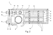
- Figure 2 shows a top view of a device (1') for conditioning of a galvanic electrolyte and for activation of electrodes of a galvanic device in accordance with another preferred embodiment of the present invention, wherein the device (1') comprises a first reaction tank (5'), which is filled with a galvanic electrolyte.
- the device (1') further comprises three electrolysis device units, wherein each electrolysis device unit comprises two cathodes (8') and one anode (7'). Between each of these neighbored electrolysis device units is a separating plate (12) arranged as electromagnetic shielding for the neighbored cathodes (8') due to their same polarity.
- a circular pump system (9') for circulating the electrolyte via a first (10') and a second (11') connection between the reaction container of the galvanic device (not shown) and the first reaction tank (5') of the device (1') for conditioning and activation, wherein the first connection (10') represents an inlet while the second connection (11') represents an outlet for the electrolyte flowing in or out of the device (1').
- the device (1') comprises a first connecting port (19) for connecting the device (1') to at least a second identical device (1', not shown) for balancing the electrolyte level inside of both devices (1').
- the device (1') further comprises an electrolyte level sensor (13) for monitoring the level of the electrolyte inside of the first reaction tank (5') of the device (1'). If the electrolyte level highly decreases, the electrolyte level sensor (13) shuts down the circular pump system (9'). If the electrolyte level highly increases, the electrolyte level sensor (13) shuts down the valves (not shown) to avoid damaging and/or contaminating them.
- an electrolyte level sensor (13) for monitoring the level of the electrolyte inside of the first reaction tank (5') of the device (1'). If the electrolyte level highly decreases, the electrolyte level sensor (13) shuts down the circular pump system (9'). If the electrolyte level highly increases, the electrolyte level sensor (13) shuts down the valves (not shown) to avoid damaging and/or contaminating them.
- the device (1') further comprises an exhaust suction device element (14) for removing of possibly generated vapors.
- the device (1) comprises as well an outer casing (16) and electrical contact rails (15), preferably composed of copper, which are connected via connecting cables (not shown) to the current contact rail for the anodes (17) and the cathodes (18). Said current contact rails (17,18) are themselves again in electrical contact to a rectifier (not shown).
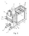
- Figure 3 shows a perspective side view of a device (1') for conditioning of a galvanic electrolyte and for activation of electrodes of a galvanic device in accordance with the same preferred embodiment of the present invention as shown in Figure 2 , wherein the device (1') comprises a first reaction tank (5'), which is filled with a galvanic electrolyte.
- the device (1') further comprises three electrolysis device units, wherein each electrolysis device unit comprises two cathodes (8') and one anode (7'). Between each of these neighbored electrolysis device units is a separating plate (12) arranged as electromagnetic shielding for the neighbored cathodes (8') due to their same polarity.
- a circular pump system (9') for circulating the electrolyte via a first (10') and a second (11') connection between the reaction container of the galvanic device (not shown) and the first reaction tank (5') of the device (1') for conditioning and activation, wherein the first connection (10') represents an inlet while the second connection (11') represents an outlet for the electrolyte flowing in or out of the device (1').
- the device (1') comprises a first connecting port (19) for connecting the device (1') to at least a second identical device (1', not shown) for balancing the electrolyte level inside of both devices (1').
- the device (1') further comprises an electrolyte level sensor (13) for monitoring the level of the electrolyte inside of the first reaction tank (5') of the device (1'). If the electrolyte level highly decreases, the electrolyte level sensor (13) shuts down the circular pump system (9'). If the electrolyte level highly increases, the electrolyte level sensor (13) shuts down the valves (not shown) to avoid damaging and/or contaminating them.
- an electrolyte level sensor (13) for monitoring the level of the electrolyte inside of the first reaction tank (5') of the device (1'). If the electrolyte level highly decreases, the electrolyte level sensor (13) shuts down the circular pump system (9'). If the electrolyte level highly increases, the electrolyte level sensor (13) shuts down the valves (not shown) to avoid damaging and/or contaminating them.
- the device (1') further comprises an exhaust suction device element (14) for removing of possibly generated vapors.
- the device (1) comprises as well an outer casing (16) and electrical contact rails (15), preferably composed of copper, which are connected via connecting cables (not shown) to the current contact rail for the anodes (17) and the cathodes (18). Said current contact rails (17,18) are themselves again in electrical contact to a rectifier (not shown).
Landscapes
- Chemical & Material Sciences (AREA)
- Engineering & Computer Science (AREA)
- Chemical Kinetics & Catalysis (AREA)
- Electrochemistry (AREA)
- Materials Engineering (AREA)
- Metallurgy (AREA)
- Organic Chemistry (AREA)
- Automation & Control Theory (AREA)
- Electrolytic Production Of Metals (AREA)
Abstract
The present invention is related to a device for conditioning of a galvanic electrolyte and for activation of electrodes of a galvanic device, which comprises at least a reaction container filled with such a galvanic electrolyte, wherein said galvanic device is supposed to be subsequently used for a galvanic metal, in particular copper, deposition process for depositing said galvanic metal on a substrate to be treated; wherein the device comprises at least a first reaction tank, which is filled with such a galvanic electrolyte, at least a first anode, at least a first cathode, at least a rectifier for adjusting and/or controlling direct current or alternating current, at least a current source, at least an electrical connection for said electrodes, a circular pump system for circulating the electrolyte via at least a first and at least a second connection between the reaction container of the galvanic device and the first reaction tank of the device for conditioning and activation; wherein decomposition products of galvanic electrolyte components are generated in the device prior to the start of the galvanic metal deposition process in the galvanic device itself.
The invention is further related to a method for conditioning of a galvanic electrolyte and for activation of electrodes of a galvanic device; and to the use of such a method making use of such a device for conditioning of a galvanic electrolyte and for activation of electrodes of a galvanic device prior to the start of the galvanic metal deposition process in the galvanic device itself.
Description
- The present invention relates to a device for conditioning of a galvanic electrolyte and for activation of electrodes of a galvanic device, which comprises at least a reaction container filled with such a galvanic electrolyte, wherein said galvanic device is supposed to be subsequently used for a galvanic metal, in particular copper, deposition process for depositing said galvanic metal on a substrate to be treated.
- The present invention is further directed to a method for conditioning of a galvanic electrolyte and for activation of electrodes of a galvanic device, which comprises at least a reaction container filled with such a galvanic electrolyte, wherein said galvanic device is supposed to be subsequently used for a galvanic metal, in particular copper, deposition process for depositing said galvanic metal on a substrate to be treated.
- Galvanic devices of the prior art, which are supposed to be used for the deposition of a galvanic metal on a substrate to be treated, are always underlying the challenge to ensure that the galvanic electrolyte and the electrodes, which are supposed to be used for the deposition of a galvanic metal, has to be kept efficient and active for the desired purpose. In particular, the individual galvanic electrolyte components, such as brighteners, levelers and other additives, have to be surveyed for their active state.
- A known problem is that such an active galvanic electrolyte for a galvanic deposition process is not easily available by just mixing the required basic electrolyte with certain amounts of further additives and individual electrolyte components, such as brighteners and levelers. Even when all components of the galvanic electrolyte are mixed to a homogenous final electrolyte solution, it is up to now still necessary for prior art devices to conduct the so-called "dummy panel plating" procedure.
- A significant number of regular panels or substrates to be treated have to be transported through the whole galvanic plating device during such a "dummy panel plating" procedure. The conditioning and activation of the electrolyte and the electrodes takes commonly place by the generated decomposition products of certain electrolyte components, such as brighteners and levelers, during this procedure. However, there is a certain period of time necessary, which is not negligible, to generate enough of said decomposition products to successfully condition and activate the electrolyte and the electrodes.
- The same applies, if the galvanic plating device has been stopped for an intermediate period of time, such as for maintenance or for a weekend, wherein no substrates to be treated are plated by such a galvanic plating device. After such a break, the galvanic electrolyte, in particular individual electrolyte components such as brighteners or levelers, is/are commonly less active than before. It is then not sufficient to just readjust the individual components back to their original higher amounts or concentrations in order to reactivate the galvanic electrolyte, in particular the brighteners. Again, the "dummy panel plating" procedure has to be conducted to recondition or reactivate the galvanic electrolyte and the electrodes of the galvanic plating device.
- Up to now, if someone simply omit or neglect the dummy panel plating procedure, the final resulting plating performance of the galvanic plating device will be tremendously decreased.
- Attempts to avoid this dummy panel plating have been partially successful by further development of more efficient galvanic electrolytes in the past, but still have been plagued with the same fundamental problem arising from the requirement still to conduct said dummy panel plating.
- Said dummy panel plating wastes a large amount of panels, which have to be thrown away after the process. Furthermore, the galvanic plating device is occupied by said process and wastes time, energy, water and chemicals during and by said dummy panel process, which makes it to a certain extent ineffective and costly.
- It is especially costly, because the dummy panels have to be transported through the whole galvanic plating device in order to avoid contamination of the galvanic plating device. However, such transportation through the whole galvanic device means that all pre and post treatment process steps, such as rinsing and cleaning, have to be executed for panels, which have to be thrown away afterwards. This increases again the costs for such a prior art procedure.
- In view of the prior art, it was thus an object of the present invention to provide a device and a method for conditioning and activation, which shall not exhibit the aforementioned shortcomings of the known prior art devices and methods.
- In particular, it was an object of the present invention to provide a device and a method, which shall be able to condition a galvanic electrolyte and to activate the electrodes of a galvanic device, which is supposed to be subsequently used for a galvanic metal, in particular copper, deposition process for depositing said galvanic metal on a substrate to be treated, while at the same time the so-called "dummy plating", as discussed above, shall be avoided.
- Additionally, it was especially an object of the present invention to provide a device and a method for conditioning and activation, which shall be generally suitable for all different kind of known horizontal or vertical galvanic plating devices, regardless if as additional external add-on module or as additional internally integrable unit.
- Further, it was an object to provide an economic device and method which shall comprise a minimum of required device elements and method steps, which shall be at the same time as cheap and as simply constructed, in case of device elements, as possible.
- These objects and also further objects which are not stated explicitly but are immediately derivable or discernible from the connections discussed herein by way of introduction are achieved by a device having all features of
claim 1. Appropriate modifications to the inventive device are protected independent claims 2 to 9. Further,claim 10 comprises a method for conditioning of a galvanic electrolyte and for activation of electrodes of a galvanic device prior to the start of a galvanic metal deposition process in the galvanic device itself. Appropriate modifications to the inventive method are protected independent claims 11 to 14; whileclaim 15 comprises the use of such an inventive method comprising such an inventive device, for conditioning of a galvanic electrolyte and for activation of electrodes of a galvanic device. - The present invention accordingly provides a device for conditioning of a galvanic electrolyte and for activation of electrodes of a galvanic device, which comprises at least a reaction container filled with such a galvanic electrolyte, wherein said galvanic device is supposed to be subsequently used for a galvanic metal, in particular copper, deposition process for depositing said galvanic metal on a substrate to be treated characterized in that the device comprises at least a first reaction tank, which is filled with such a galvanic electrolyte, at least a first anode, at least a first cathode, at least a rectifier for adjusting and/or controlling direct current or alternating current, at least a current source, at least an electrical connection for said electrodes, a circular pump system for circulating the electrolyte via at least a first and at least a second connection between the reaction container of the galvanic device and the first reaction tank of the device for conditioning and activation; wherein decomposition products of galvanic electrolyte components are generated in the device prior to the start of the galvanic metal deposition process in the galvanic device itself.
- It is thus possible in an unforeseeable manner to provide a device for conditioning and activation, which does not exhibit the aforementioned shortcomings of the known prior art devices.
- In addition thereto, the device and the method are able to condition a galvanic electrolyte and to activate the electrodes of a galvanic device, which is supposed to be subsequently used for a galvanic metal, in particular copper, deposition process for depositing said galvanic metal on a substrate to be treated, while at the same time the so-called "dummy plating", as discussed above, can be avoided.
- Additionally, the device and the method for conditioning and activation of the present invention is generally suitable for all different kind of known horizontal or vertical galvanic plating devices, wherein the device can comprise an additional external add-on module or an additional internally integrable unit.
- Further, the device and the method of the present invention comprises solely a minimum of device elements and method steps, which are as cheap and as simply constructed, in case of device elements, as possible.
- It has been found especially advantageous that the device and the method of the present invention is suitable to tremendously reduce cost of any kind of galvanic plating process by avoiding the so-called "dummy plating" whereby no dummy panels have to be wasted no more. The waste of man power and material is also achieved by reducing the required amount of time, chemistry, water and energy, which normally have to be spend for all pretreatment and post treatment steps in such known galvanic plating devices and processes, wherein the common "dummy panel plating" had to be conducted up to now.
- Objects, features, and advantages of the present invention will also become apparent upon reading the following description in conjunction with the figures, in which:
-
Fig. 1 exhibits a schematic illustrative side view of a device in accordance with a preferred embodiment of the present invention. -
Fig. 2 exhibits a top view of a device in accordance with another preferred embodiment of the present invention. -
Fig. 3 exhibits a perspective side view of a device in accordance with the same preferred embodiment of the present invention as shown inFigure 2 . - As used herein, the term "galvanic metal", when applied in accordance with the present invention, refers to metals which are known to be generally suitable for a galvanic metal deposition method. Such galvanic metals can comprise gold, nickel, and copper, preferably copper.
- As used herein, the term "substrate to be treated", when applied in accordance with the present invention, refers to substrates which are round, preferably circular, or angular, preferably polyangular, such as rectangular, quadratic or triangular, or a mixture of round and angular structure elements, such as semicircular.
- Such substrates have a diameter ranging from 50 mm to 1000 mm, preferably from 100 mm to 700 mm, and more preferably from 120 mm to 500 mm, in case of a round structure; or a side length ranging from 10 mm to 1000 mm, preferably from 25 mm to 700 mm, and more preferably from 50 mm to 500 mm, in case of an angular, preferably polyangular, structure.
- Such substrates can be a printed circuit board, a printed circuit foil, a semiconductor wafer, a solar cell, a photoelectric cell or a monitor cell.
- As used herein, the term "electrodes", when applied in accordance with the present invention, refers to electrodes, which are generally suitable for a galvanic metal plating process making use of any kind of a galvanic metal plating device, independently if the galvanic metal plating process is a vertical or horizontal process. Electrodes can be comprised of an insoluble material, such as titanium coated with iridium oxide, and/or of a soluble material, such as a soluble anode composed of copper (sacrificial anode).
- It is preferred that the electrodes are arranged vertically inside of the first reaction tank of the inventive device for conditioning and activation.
- As used herein, the term "galvanic device", when applied in accordance with the present invention, refers to any kind of galvanic device, which is suitable for a galvanic metal plating process, independently if the galvanic metal plating process is a vertical or horizontal process.
- As used herein, the term "galvanic electrolyte", when applied in accordance with the present invention, refers to any kind of galvanic electrolyte, which is suitable for a galvanic metal plating process, independently if the galvanic metal plating process is a vertical or horizontal process. This general definition shall include all kind of generally suitable individual electrolyte components known in the prior art, such as brighteners and levelers.
- Herein, it has been found advantageous if the galvanic electrolyte in the reaction container of the galvanic device is identical to the galvanic electrolyte in the first reaction tank of the inventive device for conditioning and activation.
- Nevertheless, both provided galvanic electrolytes could also be different at the beginning of the inventive method. However, both galvanic electrolytes would become identical again over time by circulating the electrolytes between the galvanic device and the device for conditioning and activation via the at least first and the at least second connection by applying the circular pump system.
- It has to be highlighted that the inventive device and method is different to known prior art devices and methods, which are commonly focusing on a circulation circle for refreshing a galvanic electrolyte. However, such a refreshing offers solely a possibility to refresh the respective galvanic electrolyte during the galvanic metal plating process by adding galvanic metal ions, preferably copper ions, in order to replace the consumed metal, preferably copper, ions, which have been already used during the galvanic metal plating process for metal, preferably copper, deposition on a substrate to be treated. In contrast thereto, the device and method of the present invention focusses on a circulation circle of the electrolyte in order to condition and activate the galvanic electrolyte prior to the start of a galvanic metal plating process by generating decomposition products of individual electrolyte components.
- In one embodiment, the device further comprises at least a first connecting port for connecting the device to at least a second identical device for balancing the electrolyte level inside of both devices.
- It can be advantageous to make use of a plurality of such devices for conditioning and activation according to the present invention, wherein said devices are interconnected to each other by such at least first connecting ports. This would offer more flexibility to the customer of such devices to install such an inventive device in dependence of the available space at customer sites.
- In one embodiment, the device further comprises at least a first means for adjusting, monitoring and/or controlling of the conditioning and activation process taking place in said device.
- The first means can comprise a measurement tool or device, which is suitable to measure the progress of the conditioning and activation in-situ by analyzing the individual electrolyte components, such as by online titration via an ancolyzer. Alternatively, such a function could also be fulfilled by manpower, wherein an user at customer site shall conduct such measurements in-situ in the classical way by common methods, such as titrations.
- In one embodiment, the device is externally connected as separated unit to the galvanic device and/or the device is a modular unit, which is connectable as internal unit to an existing galvanic device.
- The internal alternative would save total space while the external alternative offers a higher flexibility for installing and arranging such additional devices to existing galvanic devices.
- In one embodiment, the ratio of the total anode area versus the total cathode area of the device is equal to the ratio of the total anode area versus the total cathode area of the respective galvanic device to which the device is operative connectable.
- Such an embodiment would offer the advantage of similarity to known process parameters of the galvanic device itself, which could be easily transferred and/or adapted to the inventive device for conditioning and activation due to the equality of the above-cited area ratios.
- In one embodiment, the ratio of the total anode area versus the total cathode area of the device is unequal to the ratio of the total anode area versus the total cathode area of the respective galvanic device to which the device is operative connectable, preferably ranging from 1.1:1 to 4:1 or from 1:1.1 to 1:4, more preferably from 1.5:1 to 3:1 or from 1:1.5 to 1:3.
- Such an embodiment would offer the advantage of flexibility regarding the adjusting of known process parameters of the galvanic device itself by changing the area ratios in such a way that modified process parameters shall be easily available for the inventive device for conditioning and activation due to the disparity of the above-cited area ratios.
- In one embodiment, the total anode area and the total cathode area of the device are equal to the respective total anode area and the respective total cathode area of the respective galvanic device to which the device is operative connectable.
- Such an embodiment would offer the advantage of similarity to known process parameters of the galvanic device itself, which could be easily transferred and/or adapted to the inventive device for conditioning and activation due to the equality of the above-cited total electrode areas.
- In one embodiment, the total anode area and the total cathode area of the device are unequal to the respective total anode area and the respective total cathode area of the respective galvanic device to which the device is operative connectable.
- Herein, if the total anode area and the total cathode area of the device are larger than the respective total anode area and the respective total cathode area of the respective galvanic device to which the device is operative connectable, there is needed more space at customer sites to arrange the respective inventive device and there is required more galvanic electrolyte to fill said larger inventive device, which makes this alternative more costly. However, the conditioning and the activation takes place faster, which saves again costs.
- Herein, if the total anode area and the total cathode area of the device are in contrast to the above-cited alternative smaller than the respective total anode area and the respective total cathode area of the respective galvanic device to which the device is operative connectable, there is needed less space at customer sites to arrange the respective inventive device and there is required less galvanic electrolyte to fill said smaller inventive device, which makes this alternative cheaper. However, the conditioning and the activation takes place slower, which increases again costs.
- Conclusively, which of both alternatives of this embodiment of the present invention is better suited, depends on the circumstances at customer sites and on the demands made for the inventive device.
- In one embodiment, the device comprises at least a first electrolysis device unit, which comprises one cathode and one anode, one cathode and two anodes or two cathodes and one anode; wherein the device further comprises at least one separating plate between neighbored electrolysis device units as electromagnetic shielding for the electrodes, if said electrodes of neighbored electrolysis device units possess the same polarity.
- Herein, if the inventive device comprises more than one electrolysis device unit, there is a need for a parallel connection for the current supply of said at least two electrolysis device units. If a connection in series is desired, it has to be noted that a complete electrical separation of the individual electrolysis device units would be necessary, which would require more space and generate more costs. Thus, parallel connection shall be preferred for the present invention.
- In case of making use of the above-cited separating plates, the electromagnetic shielding relates to a shielding of the electric flux lines between neighbored electrodes of same polarity, not to a complete separation of the individual electrolysis device units from each other.
- Further, the object of the present invention is also solved by a method for conditioning of a galvanic electrolyte and for activation of electrodes of a galvanic device, which comprises at least a reaction container filled with such a galvanic electrolyte, wherein said galvanic device is supposed to be subsequently used for a galvanic metal, in particular copper, deposition process for depositing said galvanic metal on a substrate to be treated characterized by the following method steps:
- i) Providing such a device for conditioning of a galvanic electrolyte and for activation of electrodes according to the present invention.
- ii) Connect the device to the respective galvanic device by at least a first and at least a second connection.
- iii) Start circulating the electrolyte between the first reaction tank of the device according to the present invention and the reaction container of the respective galvanic device by a circular pump system via the at least first and second connection.
- iv) Start conditioning of the galvanic electrolyte and activation of the electrodes, which are located in the reaction container of the respective galvanic device, by applying current to the electrodes of the device according to the present invention.
- v) Generate decomposition products of galvanic electrolyte components in the device according to the present invention prior to the start of the galvanic metal deposition process in the galvanic device itself.
- vi) Circulate the generated decomposition products of galvanic electrolyte components between the device according to the present invention and the galvanic device by the circular pump system.
- vii) Finish applying current to the electrodes of the device according to the present invention.
- viii) Terminate running of the circular pump system and disconnect the device according to the present invention from the respective galvanic device, which is supposed to be subsequently used for the galvanic metal, in particular copper, deposition on a substrate to be treated.
- Alternatively, method steps iii) and iv) could also be executed in reversed order, but solely if the difference in the chronology is not getting too high, meaning that step iii) follows step iv) very lately, such as a couple hours later. Then, there would be the risk that the electrolyte in the inventive device is getting depleted without starting the circulation of the electrolyte on time.
- In one embodiment of the method, the method further comprises an intermediate step (vii') between step vii) and step viii) if the galvanic electrolyte comprises an oxidizing agent, preferably Fe3+ ions; wherein the device according to the present invention stays so long connected to the galvanic device during the subsequently started galvanic metal deposition process until all copper which had been before deposited on the surface of the at least one cathode in the first reaction tank of the device according to the present invention has been dissolved again to the galvanic electrolyte by oxidizing the deposited copper to copper ions.
- In one embodiment of the method, the applied current in method step iv) can be direct current or alternating current.
- Alternating current has been found advantageous, if it is desired to redissolve deposited galvanic metal, preferably copper, from the cathode of the inventive device in the electrolyte during the conditioning and activation method in order to minimize the amount of consumed galvanic metal, preferably copper, which can reduce the costs of the inventive method. It shall also save the amount of required electrolyte.
- In one embodiment of the method, the current is applied to the electrodes of the device according to the present invention by a parallel connection, if the device according to the present invention comprises more than one electrolysis device units, which comprises one cathode and one anode, one cathode and two anodes or two cathodes and one anode; wherein the device according to the present invention further comprises at least one separating plate between neighbored electrolysis device units as electromagnetic shielding for the electrodes, if said electrodes of neighbored electrolysis device units possess the same polarity.
- In one embodiment of the method, method steps iii), iv), v) and vi) are conducted for a certain period of time to be specified, which can be adjusted, monitored and/or controlled manually by an user and/or automatically by an at least first means for adjusting, monitoring and/or controlling.
- Additionally, the object of the present invention is also solved by making use of a method according to according to the present invention, which makes use of a device according to the present invention, for conditioning of a galvanic electrolyte and for activation of electrodes of a galvanic device, which comprises at least a reaction container filled with such a galvanic electrolyte, wherein said galvanic device is supposed to be subsequently used for a galvanic metal, in particular copper, deposition process for depositing said galvanic metal on a substrate to be treated.
- The present invention thus addresses the problem of avoiding the so-called "dummy panel plating", wherein a plurality of panels have to be run through the entire respective galvanic plating device in order to condition the galvanic electrolyte and to activate the electrodes of the reaction container of such a galvanic device for depositing a galvanic metal on a substrate to be treated. The inventive device and method offer a way to avoid the main part of the generated costs which have been arising up to now by the force to conduct the dummy panel plating and thereby being forced to waste manpower, water, chemistry and energy.
- The following non-limiting examples are provided to illustrate an embodiment of the present invention and to facilitate understanding of the invention, but are not intended to limit the scope of the invention, which is defined by the claims appended hereto.
- Turning now to the Figures,
Figure 1 shows a schematic illustrative side view of a device (1) for conditioning of a galvanic electrolyte (6) and for activation of electrodes of a galvanic device in accordance with a preferred embodiment of the present invention, wherein the device (1) comprises a first reaction tank (5), which is filled with a galvanic electrolyte (6). - The device (1) further comprises six electrolysis device units, wherein each electrolysis device unit comprises one cathode (8) and two anodes (7). Between each of these neighbored electrolysis device units has to be arranged a separating plate (12, not shown in this Figure) as electromagnetic shielding for the neighbored anodes (7) due to their same polarity.
- The device (1) additionally comprises a rectifier (2) for adjusting and/or controlling direct current or alternating current, at least a current source (not shown) for providing current to the electrodes, one electrical connection (3) for the anodes and one electrical connection (4) for the cathodes of the electrolysis device units of the device (1).
- Further, there is provided a circular pump system (9) for circulating the electrolyte (6) via a first (10) and a second (11) connection between the reaction container of the galvanic device (not shown) and the first reaction tank (5) of the device (1) for conditioning and activation, wherein the first connection (10) represents an inlet while the second connection (11) represents an outlet for the electrolyte flowing in or out of the device (1).
-
Figure 2 shows a top view of a device (1') for conditioning of a galvanic electrolyte and for activation of electrodes of a galvanic device in accordance with another preferred embodiment of the present invention, wherein the device (1') comprises a first reaction tank (5'), which is filled with a galvanic electrolyte. - The device (1') further comprises three electrolysis device units, wherein each electrolysis device unit comprises two cathodes (8') and one anode (7'). Between each of these neighbored electrolysis device units is a separating plate (12) arranged as electromagnetic shielding for the neighbored cathodes (8') due to their same polarity.
- Further, there is provided a circular pump system (9') for circulating the electrolyte via a first (10') and a second (11') connection between the reaction container of the galvanic device (not shown) and the first reaction tank (5') of the device (1') for conditioning and activation, wherein the first connection (10') represents an inlet while the second connection (11') represents an outlet for the electrolyte flowing in or out of the device (1').
- Additionally, the device (1') comprises a first connecting port (19) for connecting the device (1') to at least a second identical device (1', not shown) for balancing the electrolyte level inside of both devices (1').
- The device (1') further comprises an electrolyte level sensor (13) for monitoring the level of the electrolyte inside of the first reaction tank (5') of the device (1'). If the electrolyte level highly decreases, the electrolyte level sensor (13) shuts down the circular pump system (9'). If the electrolyte level highly increases, the electrolyte level sensor (13) shuts down the valves (not shown) to avoid damaging and/or contaminating them.
- The device (1') further comprises an exhaust suction device element (14) for removing of possibly generated vapors. The device (1) comprises as well an outer casing (16) and electrical contact rails (15), preferably composed of copper, which are connected via connecting cables (not shown) to the current contact rail for the anodes (17) and the cathodes (18). Said current contact rails (17,18) are themselves again in electrical contact to a rectifier (not shown).
-
Figure 3 shows a perspective side view of a device (1') for conditioning of a galvanic electrolyte and for activation of electrodes of a galvanic device in accordance with the same preferred embodiment of the present invention as shown inFigure 2 , wherein the device (1') comprises a first reaction tank (5'), which is filled with a galvanic electrolyte. - The device (1') further comprises three electrolysis device units, wherein each electrolysis device unit comprises two cathodes (8') and one anode (7'). Between each of these neighbored electrolysis device units is a separating plate (12) arranged as electromagnetic shielding for the neighbored cathodes (8') due to their same polarity.
- Further, there is provided a circular pump system (9') for circulating the electrolyte via a first (10') and a second (11') connection between the reaction container of the galvanic device (not shown) and the first reaction tank (5') of the device (1') for conditioning and activation, wherein the first connection (10') represents an inlet while the second connection (11') represents an outlet for the electrolyte flowing in or out of the device (1').
- Additionally, the device (1') comprises a first connecting port (19) for connecting the device (1') to at least a second identical device (1', not shown) for balancing the electrolyte level inside of both devices (1').
- The device (1') further comprises an electrolyte level sensor (13) for monitoring the level of the electrolyte inside of the first reaction tank (5') of the device (1'). If the electrolyte level highly decreases, the electrolyte level sensor (13) shuts down the circular pump system (9'). If the electrolyte level highly increases, the electrolyte level sensor (13) shuts down the valves (not shown) to avoid damaging and/or contaminating them.
- The device (1') further comprises an exhaust suction device element (14) for removing of possibly generated vapors. The device (1) comprises as well an outer casing (16) and electrical contact rails (15), preferably composed of copper, which are connected via connecting cables (not shown) to the current contact rail for the anodes (17) and the cathodes (18). Said current contact rails (17,18) are themselves again in electrical contact to a rectifier (not shown).
- It will be understood that the embodiments described herein are merely exemplary and that a person skilled in the art may make many variations and modifications without departing from the spirit and scope of the invention. All such variations and modifications, including those discussed above, are intended to be included within the scope of the invention as defined by the appended claims.
-
- 1,1'
- Device for conditioning and activation
- 2
- Rectifier for adjusting and/or controlling current
- 3
- Electrical connection
- 4
- Electrical connection
- 5, 5'
- First reaction tank
- 6
- Electrolyte
- 7, 7'
- Anode
- 8, 8'
- Cathode
- 9, 9'
- Circular pump system
- 10, 10'
- First connection for the electrolyte
- 11, 11'
- Second connection for the electrolyte
- 12
- Separating plate
- 13
- Electrolyte level sensor
- 14
- Exhaust suction device element
- 15
- Electrical contact rails
- 16
- Outer casing of the device
- 17
- Current contact rail for anodes
- 18
- Current contact rail for cathodes
- 19
- First connecting port
Claims (15)
- Device (1) for conditioning of a galvanic electrolyte (6) and for activation of electrodes of a galvanic device, which comprises at least a reaction container filled with such a galvanic electrolyte (6), wherein said galvanic device is supposed to be subsequently used for a galvanic metal, in particular copper, deposition process for depositing said galvanic metal on a substrate to be treated characterized in that
the device (1) comprises at least a first reaction tank (5), which is filled with such a galvanic electrolyte (6), at least a first anode (7), at least a first cathode (8), at least a rectifier (2) for adjusting and/or controlling direct current or alternating current, at least a current source, at least an electrical connection (3,4) for said electrodes (7,8), a circular pump system (9) for circulating the electrolyte (6) via at least a first (10) and at least a second (11) connection between the reaction container of the galvanic device and the first reaction tank (5) of the device (1) for conditioning and activation; wherein decomposition products of galvanic electrolyte components are generated in the device (1) prior to the start of the galvanic metal deposition process in the galvanic device itself. - Device according to claim 1 characterized in that the device (1) further comprises at least a first connecting port (19) for connecting the device (1) to at least a second identical device (1) for balancing the electrolyte level inside of both devices (1).
- Device according to claim 1 or 2 characterized in that the device (1) further comprises at least a first means for adjusting, monitoring and/or controlling of the conditioning and activation process taking place in said device.
- Device according to one of the preceding claims characterized in that the device (1) is externally connected as separated unit to the galvanic device and/or the device (1) is a modular unit, which is connectable as internal unit to an existing galvanic device.
- Device according to one of the preceding claims characterized in that the ratio of the total anode area versus the total cathode area of the device (1) is equal to the ratio of the total anode area versus the total cathode area of the respective galvanic device to which the device (1) is operative connectable.
- Device according to one of the preceding claims characterized in that the ratio of the total anode area versus the total cathode area of the device (1) is unequal to the ratio of the total anode area versus the total cathode area of the respective galvanic device to which the device (1) is operative connectable, preferably ranging from 1.1:1 to 4:1 or from 1:1.1 to 1:4, more preferably from 1.5:1 to 3:1 or from 1:1.5 to 1:3.
- Device according to one of the preceding claims characterized in that the total anode area and the total cathode area of the device (1) are equal to the respective total anode area and the respective total cathode area of the respective galvanic device to which the device (1) is operative connectable.
- Device according to one of the preceding claims characterized in that the total anode area and the total cathode area of the device (1) are unequal to the respective total anode area and the respective total cathode area of the respective galvanic device to which the device (1) is operative connectable.
- Device according to one of the preceding claims characterized in that the device (1) comprises at least a first electrolysis device unit, which comprises one cathode (8) and one anode (7), one cathode (8) and two anodes (7) or two cathodes (8) and one anode (7); wherein the device (1) further comprises at least one separating plate (12) between neighbored electrolysis device units as electromagnetic shielding for the electrodes (7,8), if said electrodes (7,8) of neighbored electrolysis device units possess the same polarity.
- Method for conditioning of a galvanic electrolyte (6) and for activation of electrodes of a galvanic device, which comprises at least a reaction container filled with such a galvanic electrolyte (6), wherein said galvanic device is supposed to be subsequently used for a galvanic metal, in particular copper, deposition process for depositing said galvanic metal on a substrate to be treated characterized by the following method steps:i) Providing a device (1) for conditioning of a galvanic electrolyte (6) and for activation of electrodes according to one of the preceding claims.ii) Connect the device (1) to the respective galvanic device by at least a first (10) and at least a second (11) connection.iii) Start circulating the electrolyte between the first reaction tank (5) of the device (1) according to one of the preceding claims and the reaction container of the respective galvanic device by a circular pump system (9) via the at least first (10) and second (11) connection.iv) Start conditioning of the galvanic electrolyte and activation of the electrodes, which are located in the reaction container of the respective galvanic device, by applying current to the electrodes (7,8) of the device (1) according to one of the preceding claims.v) Generate decomposition products of galvanic electrolyte (6) components in the device (1) prior to the start of the galvanic metal deposition process in the galvanic device itself.vi) Circulate the generated decomposition products of galvanic electrolyte (6) components between the device (1) and the galvanic device by the circular pump system (9).vii) Finish applying current to the electrodes of the device according to one of the preceding claims.viii) Terminate running of the circular pump system and disconnect the device (1) from the respective galvanic device, which is supposed to be subsequently used for the galvanic metal, in particular copper, deposition on a substrate to be treated.
- Method according to claim 10 characterized in that the method further comprises an intermediate step (vii') between step vii) and step viii) if the galvanic electrolyte (6) comprises an oxidizing agent, preferably Fe3+ ions; wherein the device (1) stays so long connected to the galvanic device during the subsequently started galvanic metal deposition process until all copper which had been before deposited on the surface of the at least one cathode (8) in the first reaction tank (5) of the device (1) has been dissolved again to the galvanic electrolyte by oxidizing the deposited copper to copper ions.
- Method according to claim 10 or 11 characterized in that the applied current in method step iv) can be direct current or alternating current.
- Method according to one of claims 10 to 12 characterized in that the current is applied to the electrodes (7,8) of the device (1) by a parallel connection, if the device (1) comprises more than one electrolysis device units, which comprises one cathode (8) and one anode (7), one cathode (8) and two anodes (7) or two cathodes (8) and one anode (7); wherein the device (1) further comprises at least one separating plate (12) between neighbored electrolysis device units as electromagnetic shielding for the electrodes (7,8), if said electrodes (7,8) of neighbored electrolysis device units possess the same polarity.
- Method according to one of claims 10 to 13 characterized in that method steps iii), iv), v) and vi) are conducted for a certain period of time to be specified, which can be adjusted, monitored and/or controlled manually by an user and/or automatically by an at least first means for adjusting, monitoring and/or controlling.
- Use of a method according to one of claims 10 to 14, which makes use of a device according to one of claims 1 to 9, for conditioning of a galvanic electrolyte (6) and for activation of electrodes of a galvanic device, which comprises at least a reaction container filled with such a galvanic electrolyte (6), wherein said galvanic device is supposed to be subsequently used for a galvanic metal, in particular copper, deposition process for depositing said galvanic metal on a substrate to be treated.
Priority Applications (3)
| Application Number | Priority Date | Filing Date | Title |
|---|---|---|---|
| EP13175010.1A EP2821530A1 (en) | 2013-07-04 | 2013-07-04 | Device and method for conditioning of a galvanic electrolyte and activation of electrodes prior to the start of a galvanic metal deposition process |
| PCT/EP2014/063764 WO2015000817A1 (en) | 2013-07-04 | 2014-06-27 | Method for conditioning of a galvanic electrolyte and activation of electrodes prior to the start of a galvanic metal deposition process |
| TW103123199A TW201508100A (en) | 2013-07-04 | 2014-07-04 | Method for conditioning of a galvanic electrolyte and activation of electrodes prior to the start of a galvanic metal deposition process |
Applications Claiming Priority (1)
| Application Number | Priority Date | Filing Date | Title |
|---|---|---|---|
| EP13175010.1A EP2821530A1 (en) | 2013-07-04 | 2013-07-04 | Device and method for conditioning of a galvanic electrolyte and activation of electrodes prior to the start of a galvanic metal deposition process |
Publications (1)
| Publication Number | Publication Date |
|---|---|
| EP2821530A1 true EP2821530A1 (en) | 2015-01-07 |
Family
ID=48703320
Family Applications (1)
| Application Number | Title | Priority Date | Filing Date |
|---|---|---|---|
| EP13175010.1A Withdrawn EP2821530A1 (en) | 2013-07-04 | 2013-07-04 | Device and method for conditioning of a galvanic electrolyte and activation of electrodes prior to the start of a galvanic metal deposition process |
Country Status (3)
| Country | Link |
|---|---|
| EP (1) | EP2821530A1 (en) |
| TW (1) | TW201508100A (en) |
| WO (1) | WO2015000817A1 (en) |
Families Citing this family (1)
| Publication number | Priority date | Publication date | Assignee | Title |
|---|---|---|---|---|
| KR101699223B1 (en) * | 2009-07-07 | 2017-01-24 | 바스프 플랜트 사이언스 컴퍼니 게엠베하 | Plants having modulated carbon partitioning and a method for making the same |
Citations (6)
| Publication number | Priority date | Publication date | Assignee | Title |
|---|---|---|---|---|
| US4067782A (en) * | 1977-05-09 | 1978-01-10 | Xerox Corporation | Method of forming an electroforming mandrel |
| JPS6436798A (en) * | 1987-07-30 | 1989-02-07 | Nec Toyama Ltd | Copper sulfate plating method |
| US20020139683A1 (en) * | 2000-05-05 | 2002-10-03 | Akihisa Hongo | Substrate plating apparatus |
| EP1264918A1 (en) * | 2001-06-07 | 2002-12-11 | Shipley Co. L.L.C. | Electrolytic copper plating method |
| US7147827B1 (en) * | 1998-05-01 | 2006-12-12 | Applied Materials, Inc. | Chemical mixing, replenishment, and waste management system |
| GB2454141A (en) * | 2006-10-19 | 2009-04-29 | Honda Motor Co Ltd | Plating apparatus |
-
2013
- 2013-07-04 EP EP13175010.1A patent/EP2821530A1/en not_active Withdrawn
-
2014
- 2014-06-27 WO PCT/EP2014/063764 patent/WO2015000817A1/en not_active Ceased
- 2014-07-04 TW TW103123199A patent/TW201508100A/en unknown
Patent Citations (6)
| Publication number | Priority date | Publication date | Assignee | Title |
|---|---|---|---|---|
| US4067782A (en) * | 1977-05-09 | 1978-01-10 | Xerox Corporation | Method of forming an electroforming mandrel |
| JPS6436798A (en) * | 1987-07-30 | 1989-02-07 | Nec Toyama Ltd | Copper sulfate plating method |
| US7147827B1 (en) * | 1998-05-01 | 2006-12-12 | Applied Materials, Inc. | Chemical mixing, replenishment, and waste management system |
| US20020139683A1 (en) * | 2000-05-05 | 2002-10-03 | Akihisa Hongo | Substrate plating apparatus |
| EP1264918A1 (en) * | 2001-06-07 | 2002-12-11 | Shipley Co. L.L.C. | Electrolytic copper plating method |
| GB2454141A (en) * | 2006-10-19 | 2009-04-29 | Honda Motor Co Ltd | Plating apparatus |
Also Published As
| Publication number | Publication date |
|---|---|
| WO2015000817A1 (en) | 2015-01-08 |
| TW201508100A (en) | 2015-03-01 |
Similar Documents
| Publication | Publication Date | Title |
|---|---|---|
| Yang et al. | Effect of a surface active agent on performance of zinc/bromine redox flow batteries: Improvement in current efficiency and system stability | |
| US11976378B2 (en) | Device and method for preventing copper plating of conductor roll | |
| TW425665B (en) | Method and apparatus for planarization of metallized semiconductor wafers using a bipolar electrode assembly | |
| US10774437B2 (en) | Method and apparatus for electrolytically depositing a deposition metal on a workpiece | |
| EP1419290B1 (en) | Segmented counterelectrode for an electrolytic treatment system | |
| KR20130057963A (en) | Membrane electrolysis stack, electrodialysis device including the stack and method for the regeneration of an electroless plating bath | |
| JP6169719B2 (en) | Device and method for electrolytic coating of objects | |
| JP7194305B1 (en) | Substrate holder, plating equipment, and plating method | |
| US6939455B1 (en) | Method and device for the electrolytic treatment of electrically conducting surfaces separated plates and film material pieces in addition to uses of said method | |
| AU2020349062B2 (en) | A system and a method for an electrochemical process | |
| JP2010539334A (en) | Current controller for feeding network of electrochemical coating equipment | |
| JP4154121B2 (en) | Method and apparatus for adjusting the concentration of a substance in an electrolyte | |
| WO2015000817A1 (en) | Method for conditioning of a galvanic electrolyte and activation of electrodes prior to the start of a galvanic metal deposition process | |
| KR102532620B1 (en) | High Efficiency Plating Device for Coil Steel Plates | |
| EP2432920A2 (en) | Method and device for the controlled electrolytic treatment of thin layers | |
| US11306405B2 (en) | Apparatus, systems and methods for high efficiency metal particle regeneration | |
| KR20200032101A (en) | Electrolytic copper plating anode and electrolytic copper plating device using the same | |
| TWI244511B (en) | Conveyorized plating line and method for electrolytically metal plating a workpiece | |
| CN101218379A (en) | Method and device for machining at least two workpieces by means of electrochemical treatment | |
| JP2024516407A (en) | DEVICE AND METHOD FOR COATING A COMPONENT OR A SEMI-FINISHED PRODUCT WITH A CHROME LAYER - Patent application | |
| JP2019052370A (en) | System for chemical and / or electrolytic surface treatment | |
| CA3089016A1 (en) | System for superimposing ac on dc in electrolytic processes | |
| CN102953115A (en) | Improved structure of coppered wire stripping and hanging recovery tank | |
| CN216737685U (en) | Anode structure for electrochemical water treatment equipment | |
| KR100801166B1 (en) | Reactor for pipeline type electrolytic equipment that maximizes reactivity with electrode |
Legal Events
| Date | Code | Title | Description |
|---|---|---|---|
| PUAI | Public reference made under article 153(3) epc to a published international application that has entered the european phase |
Free format text: ORIGINAL CODE: 0009012 |
|
| 17P | Request for examination filed |
Effective date: 20130704 |
|
| AK | Designated contracting states |
Kind code of ref document: A1 Designated state(s): AL AT BE BG CH CY CZ DE DK EE ES FI FR GB GR HR HU IE IS IT LI LT LU LV MC MK MT NL NO PL PT RO RS SE SI SK SM TR |
|
| AX | Request for extension of the european patent |
Extension state: BA ME |
|
| STAA | Information on the status of an ep patent application or granted ep patent |
Free format text: STATUS: THE APPLICATION IS DEEMED TO BE WITHDRAWN |
|
| 18D | Application deemed to be withdrawn |
Effective date: 20150708 |