EP2821121A1 - Co2 recovery device - Google Patents
Co2 recovery device Download PDFInfo
- Publication number
- EP2821121A1 EP2821121A1 EP12867698.8A EP12867698A EP2821121A1 EP 2821121 A1 EP2821121 A1 EP 2821121A1 EP 12867698 A EP12867698 A EP 12867698A EP 2821121 A1 EP2821121 A1 EP 2821121A1
- Authority
- EP
- European Patent Office
- Prior art keywords
- exhaust gas
- recovery device
- volume
- recovery
- flow rate
- Prior art date
- Legal status (The legal status is an assumption and is not a legal conclusion. Google has not performed a legal analysis and makes no representation as to the accuracy of the status listed.)
- Granted
Links
Images




Classifications
-
- B—PERFORMING OPERATIONS; TRANSPORTING
- B01—PHYSICAL OR CHEMICAL PROCESSES OR APPARATUS IN GENERAL
- B01D—SEPARATION
- B01D53/00—Separation of gases or vapours; Recovering vapours of volatile solvents from gases; Chemical or biological purification of waste gases, e.g. engine exhaust gases, smoke, fumes, flue gases, aerosols
- B01D53/14—Separation of gases or vapours; Recovering vapours of volatile solvents from gases; Chemical or biological purification of waste gases, e.g. engine exhaust gases, smoke, fumes, flue gases, aerosols by absorption
- B01D53/1456—Removing acid components
- B01D53/1475—Removing carbon dioxide
-
- B—PERFORMING OPERATIONS; TRANSPORTING
- B01—PHYSICAL OR CHEMICAL PROCESSES OR APPARATUS IN GENERAL
- B01D—SEPARATION
- B01D53/00—Separation of gases or vapours; Recovering vapours of volatile solvents from gases; Chemical or biological purification of waste gases, e.g. engine exhaust gases, smoke, fumes, flue gases, aerosols
- B01D53/14—Separation of gases or vapours; Recovering vapours of volatile solvents from gases; Chemical or biological purification of waste gases, e.g. engine exhaust gases, smoke, fumes, flue gases, aerosols by absorption
- B01D53/1412—Controlling the absorption process
-
- B—PERFORMING OPERATIONS; TRANSPORTING
- B01—PHYSICAL OR CHEMICAL PROCESSES OR APPARATUS IN GENERAL
- B01D—SEPARATION
- B01D53/00—Separation of gases or vapours; Recovering vapours of volatile solvents from gases; Chemical or biological purification of waste gases, e.g. engine exhaust gases, smoke, fumes, flue gases, aerosols
- B01D53/34—Chemical or biological purification of waste gases
- B01D53/46—Removing components of defined structure
- B01D53/62—Carbon oxides
-
- B—PERFORMING OPERATIONS; TRANSPORTING
- B01—PHYSICAL OR CHEMICAL PROCESSES OR APPARATUS IN GENERAL
- B01D—SEPARATION
- B01D53/00—Separation of gases or vapours; Recovering vapours of volatile solvents from gases; Chemical or biological purification of waste gases, e.g. engine exhaust gases, smoke, fumes, flue gases, aerosols
- B01D53/34—Chemical or biological purification of waste gases
- B01D53/74—General processes for purification of waste gases; Apparatus or devices specially adapted therefor
- B01D53/77—Liquid phase processes
- B01D53/78—Liquid phase processes with gas-liquid contact
-
- F—MECHANICAL ENGINEERING; LIGHTING; HEATING; WEAPONS; BLASTING
- F01—MACHINES OR ENGINES IN GENERAL; ENGINE PLANTS IN GENERAL; STEAM ENGINES
- F01K—STEAM ENGINE PLANTS; STEAM ACCUMULATORS; ENGINE PLANTS NOT OTHERWISE PROVIDED FOR; ENGINES USING SPECIAL WORKING FLUIDS OR CYCLES
- F01K5/00—Plants characterised by use of means for storing steam in an alkali to increase steam pressure, e.g. of Honigmann or Koenemann type
- F01K5/02—Plants characterised by use of means for storing steam in an alkali to increase steam pressure, e.g. of Honigmann or Koenemann type used in regenerative installation
-
- F—MECHANICAL ENGINEERING; LIGHTING; HEATING; WEAPONS; BLASTING
- F23—COMBUSTION APPARATUS; COMBUSTION PROCESSES
- F23J—REMOVAL OR TREATMENT OF COMBUSTION PRODUCTS OR COMBUSTION RESIDUES; FLUES
- F23J15/00—Arrangements of devices for treating smoke or fumes
- F23J15/02—Arrangements of devices for treating smoke or fumes of purifiers, e.g. for removing noxious material
- F23J15/04—Arrangements of devices for treating smoke or fumes of purifiers, e.g. for removing noxious material using washing fluids
-
- B—PERFORMING OPERATIONS; TRANSPORTING
- B01—PHYSICAL OR CHEMICAL PROCESSES OR APPARATUS IN GENERAL
- B01D—SEPARATION
- B01D2252/00—Absorbents, i.e. solvents and liquid materials for gas absorption
- B01D2252/20—Organic absorbents
- B01D2252/204—Amines
-
- B—PERFORMING OPERATIONS; TRANSPORTING
- B01—PHYSICAL OR CHEMICAL PROCESSES OR APPARATUS IN GENERAL
- B01D—SEPARATION
- B01D2258/00—Sources of waste gases
- B01D2258/02—Other waste gases
- B01D2258/0283—Flue gases
-
- F—MECHANICAL ENGINEERING; LIGHTING; HEATING; WEAPONS; BLASTING
- F23—COMBUSTION APPARATUS; COMBUSTION PROCESSES
- F23J—REMOVAL OR TREATMENT OF COMBUSTION PRODUCTS OR COMBUSTION RESIDUES; FLUES
- F23J2215/00—Preventing emissions
- F23J2215/50—Carbon dioxide
-
- F—MECHANICAL ENGINEERING; LIGHTING; HEATING; WEAPONS; BLASTING
- F23—COMBUSTION APPARATUS; COMBUSTION PROCESSES
- F23J—REMOVAL OR TREATMENT OF COMBUSTION PRODUCTS OR COMBUSTION RESIDUES; FLUES
- F23J2219/00—Treatment devices
- F23J2219/40—Sorption with wet devices, e.g. scrubbers
-
- Y—GENERAL TAGGING OF NEW TECHNOLOGICAL DEVELOPMENTS; GENERAL TAGGING OF CROSS-SECTIONAL TECHNOLOGIES SPANNING OVER SEVERAL SECTIONS OF THE IPC; TECHNICAL SUBJECTS COVERED BY FORMER USPC CROSS-REFERENCE ART COLLECTIONS [XRACs] AND DIGESTS
- Y02—TECHNOLOGIES OR APPLICATIONS FOR MITIGATION OR ADAPTATION AGAINST CLIMATE CHANGE
- Y02C—CAPTURE, STORAGE, SEQUESTRATION OR DISPOSAL OF GREENHOUSE GASES [GHG]
- Y02C20/00—Capture or disposal of greenhouse gases
- Y02C20/40—Capture or disposal of greenhouse gases of CO2
-
- Y—GENERAL TAGGING OF NEW TECHNOLOGICAL DEVELOPMENTS; GENERAL TAGGING OF CROSS-SECTIONAL TECHNOLOGIES SPANNING OVER SEVERAL SECTIONS OF THE IPC; TECHNICAL SUBJECTS COVERED BY FORMER USPC CROSS-REFERENCE ART COLLECTIONS [XRACs] AND DIGESTS
- Y02—TECHNOLOGIES OR APPLICATIONS FOR MITIGATION OR ADAPTATION AGAINST CLIMATE CHANGE
- Y02E—REDUCTION OF GREENHOUSE GAS [GHG] EMISSIONS, RELATED TO ENERGY GENERATION, TRANSMISSION OR DISTRIBUTION
- Y02E20/00—Combustion technologies with mitigation potential
- Y02E20/32—Direct CO2 mitigation
Definitions
- the present invention relates to a CO 2 recovery device that can cause a recovery rate to follow fluctuations of the volume of exhaust gas accompanied with fluctuations of the load of an apparatus located on an upstream side.
- CO 2 carbon dioxide
- a method of bringing a combustion gas of a boiler into contact with an absorbent and eliminating and recovering CO 2 in the combustion gas, and a method of storing the recovered CO 2 without discharging the CO 2 to the atmospheric have been extensively studied for, for example, power generation facilities, such as a thermoelectric power plant that uses a large quantity of fossil fuels.
- CO 2 recovery devices include, as basic constituent elements, an absorption tower that causes CO 2 in gas to be absorbed into an absorbent, and a regeneration tower that separates CO 2 from the absorbent.
- an absorption tower that causes CO 2 in gas to be absorbed into an absorbent
- a regeneration tower that separates CO 2 from the absorbent.
- the volume of exhaust gas required for attaining an objective is determined from a target CO 2 recovery volume and CO 2 concentration in the exhaust gas, and the exhaust gas is supplied to a CO 2 recovery device (for example, PTL 1).
- the volume of exhaust gas from an exhaust gas source (a boiler or a gas turbine installed upstream of a CO 2 recovery device) and CO 2 concentration in the exhaust gas are measured, and operation parameters required for achieving a target CO 2 recovery rate are determined (for example, PTL 2).
- the flow rate of the gas discharged to the atmosphere through a chimney without being treated by a CO 2 recovery device, and the composition of this gas are measured using the gas from an exhaust gas source, and the volume of exhaust gas to be supplied to the CO 2 recovery device is determined so as not to produce a stream that flows into the chimney from the atmosphere (for example, PTL 3).
- the invention has been made on the basis of such technical problems, and an object thereof is to provide a CO 2 recovery device that can cause the recovery rate of CO 2 to follow a constant rate and can partially treat exhaust gas, even if the load on an upstream side fluctuates and the volume of the exhaust gas fluctuates.
- a CO 2 recovery device of the invention includes a CO 2 absorption tower that brings an exhaust gas containing CO 2 into contact with an absorbent to eliminate CO 2 in the exhaust gas; and a regeneration tower that eliminates and regenerates CO 2 in a rich solution that has absorbed CO 2 in the CO 2 absorption tower, and the absorbent, which is a lean solution from which CO 2 is eliminated in the regeneration tower, is reused in the CO 2 absorption tower.
- the CO 2 recovery device of the invention sets an exhaust gas treatment rate R G1 and a CO 2 recovery rate R CO2 shown below as operation parameters of the CO 2 recovery device.
- a target treatment volume for exhaust gas to be treated by the CO 2 recovery device is specified on the basis of the product of an actual flow rate of the exhaust gas discharged toward the CO 2 recovery device from a generation source of the exhaust gas, and the exhaust gas treatment rate R G1 .
- a target recovery volume for CO 2 to be recovered by the CO 2 recovery device is specified on the basis of the product of an actual volume of CO 2 contained in the exhaust gas discharged from the generation source of the exhaust gas to the CO 2 recovery device, the exhaust gas treatment rate R G1 , and the CO 2 recovery rate R CO2 .
- R G ⁇ 1 T CO ⁇ 2 / V G ⁇ 1
- the actual flow rate of the exhaust gas and the actual volume of CO 2 contained in the exhaust gas can be directly obtained by measuring the exhaust gas. Additionally, the actual flow rate of the exhaust gas can be indirectly obtained by calculation based on a flow rate of fuel and a flow rate of combustion gas to be supplied to the generation source of the exhaust gas, and the actual volume of CO 2 contained in the exhaust gas can be indirectly obtained by calculation on the basis of the flow rates and composition of the fuel and the combustion gas.
- the actual flow rate of the exhaust gas is obtained by collating data in which a load to the generation source of the exhaust gas and the flow rate of the exhaust gas are matched, with a load command signal to the generation source of the exhaust gas, and the target recovery volume of the CO 2 is specified.
- an upper limit can be set to the recovery volume of CO 2 on the basis of the load of the generation source of exhaust gas.
- the steam to be consumed in an upstream plant is used for a power source of the CO 2 recovery device
- the volume of the steam to be consumed by the CO 2 recovery device increases too much, there is a concern that the volume of the steam that can be consumed by the upstream plant is just as scarce. Therefore, the volume of the steam to be consumed by the CO 2 recovery device is limited by setting an upper limit to the CO 2 recovery volume in the CO 2 recovery device.
- a target value of an absorbent circulation flow rate can be set on the basis of the load of the generation source of the exhaust gas.
- the load followability can be improved by fluctuating the absorbent circulation flow rate so as to follow this flow rate.
- a CO 2 recovery device that can cause the recovery rate of CO 2 to follow a constant rate and can partially treat exhaust gas, even if the load on an upstream side fluctuates and the volume of the exhaust gas fluctuates.
- the CO 2 recovery device (hereinafter simply referred to as a recovery device) 10 includes, for example, an absorption tower 13 that brings exhaust gas G1 containing CO 2 and O 2 , which are discharged from a boiler 11 constituting a power generation plant 40 using fossil fuels, into contact with an absorbent AL, to eliminate CO 2 from the exhaust gas G1, and a regeneration tower 14 that discharges CO 2 from a rich solution RL that is the absorbent that has absorbed CO 2 , to regenerate the absorbent AL, as main constituent elements.
- a lean solution RAL that is the regenerated absorbent from which CO 2 has been eliminated by the regeneration tower 14 is reused as absorbent AL by the absorption tower 13.
- the recovery device 10 includes a recovery control unit 30.
- the recovery control unit 30 functions so as to cause the recovery rate of CO 2 to follow a constant rate and realize partial treatment of the exhaust gas, even if the load of the power generation plant 40 located on an upstream side fluctuates and the volume of the exhaust gas fluctuates.
- the exhaust gas G1 containing CO 2 from the boiler 11 is sent to the absorption tower 13 through a flow channel F1 that connects the boiler 11 and the absorption tower 13.
- a main valve 12 that adjusts the volume of the exhaust gas G1 to be supplied to the absorption tower 13 is provided on the flow channel F1.
- a flow channel F2 branches from the flow channel F1, and a tip of the flow channel F2 where the branch valve 16 is provided is connected to a chimney 15.
- the branch valve 16 adjusts the volume of discharge of the exhaust gas G1 from the chimney 15.
- An exhaust gas flow rate sensor 24 that measures the flow rate (actual exhaust gas flow rate or measurement value V G1 ) of the whole exhaust gas G1 discharged from the boiler 11, and a CO 2 concentration sensor 25 that measures the concentration (measurement value Y CO2 ) of CO 2 contained in the exhaust gas G1 are provided on the flow channel F1.
- the information (measurement value V G1 , measurement value Y CO2 ) measured by the exhaust gas flow rate sensor 24 and the CO 2 concentration sensor 25 is continuously transmitted to the recovery control unit 30 during the operation of the power generation plant 40 and the boiler 11.
- the actual volume of CO 2 contained in the exhaust gas G1 can be obtained by multiplying the measurement value V G1 by the measurement value Y CO2 .
- the invention does not hinder providing other elements, such as a blower that raises the pressure of the exhaust gas, a cooling tower that cools the exhaust gas G1, and a denitration/desulfurization facility, between the boiler 11 and the absorption tower 13.
- the exhaust gas G1 comes into countercurrent contact with the absorbent AL having, for example, an amine-based solution as a base, and CO 2 in the exhaust gas G1 is absorbed into the absorbent AL by a chemical reaction.
- the exhaust gas G2 after CO 2 has been eliminated comes into vapor-liquid contact with condensed water containing the absorbent AL supplied to the absorption tower 13, and the absorbent AL accompanied with the exhaust gas G2 is recovered, and is then discharged from the system.
- the rich solution RL that has absorbed CO 2 is raised in pressure by a rich solvent pump 17, is heated by the lean solution RAL, which is the absorbent regenerated by the regeneration tower 14, in a rich/lean solvent heat exchanger 19 via a rich solvent valve 18, and is supplied to the regeneration tower 14.
- the absorption tower 13 and the regeneration tower 14 are connected by a flow channel F3, and the rich solvent pump 17, the rich solvent valve 18, and the rich/lean solvent heat exchanger 19 are provided in order from the absorption tower 13 side in the flow channel F3.
- the rich solution RL that has absorbed CO 2 is supplied to the regeneration tower 14 through the flow channel F3.
- the rich solution RL discharged from an upper portion of the regeneration tower 14 to the inside thereof causes an endothermic reaction, and discharges a large portion of CO 2 .
- the absorbent that has discharged a portion or a large portion of CO 2 within the regeneration tower 14 is referred to as a semi-lean solution RAL.
- the semi-lean solution RAL reaches the lower portion of the regeneration tower 14, the solution is turned into the absorbent from which almost all CO 2 has been eliminated, that is, a lean solution RAL.
- the lean solution RAL is superheated with steam S by the regeneration superheater 22, and is supplied to the inside of the regeneration tower 14 as steam.
- the steam S supplied to the regeneration superheater 22 is circulated, for example, between the regeneration superheater and the power generation plant 40. Also, the supply volume of the steam S supplied to the regeneration superheater 22 is controlled by a steam valve 23 provided on a flow channel F5.
- the CO 2 gas is discharged from the system and separately recovered after steam is condensed, for example by a condenser, and water is separated by a separation drum.
- the recovered CO 2 gas is pressed into an oil field on the basis of an enhanced oil recovery (EOR) method, or is stored in a water bearing stratum to establish global warming countermeasures.
- EOR enhanced oil recovery
- the separated water is supplied to the upper portion of the regeneration tower 14.
- the regenerated absorbent (lean solution RAL) is pumped by a lean solvent pump 20, and is sent toward the rich/lean solvent heat exchanger 19 via a lean solvent valve 21. Also, the lean solution RAL is supplied to the absorption tower 13 after being cooled by the rich solution RL in the rich/lean solvent heat exchanger 19.
- the regeneration tower 14 and the absorption tower 13 are connected by a flow channel F4, and the lean solvent pump 20, the lean solvent valve 21, and the rich/lean solvent heat exchanger 19 are provided in order from the regeneration tower 14 side in the flow channel F4.
- the lean solution RAL is returned to the absorption tower 13 through the flow channel F4.
- the recovery device 10 recovers CO 2 continuously from the exhaust gas G1 discharged from the boiler 11.
- the recovery control unit 30 adjusts the opening degrees of the main valve 12 and the branch valve 16 to control the volume (exhaust gas treatment rate) of the exhaust gas G1 to be treated by the recovery device 10. Additionally, the recovery control unit 30 adjusts the operation and opening degrees of the rich solvent pump 17, the rich solvent valve 18, the lean solvent pump 20, the lean solvent valve 21, and the steam valve 23 to control the volume (CO 2 recovery volume) of CO 2 to be recovered by the absorption tower 13 and the regeneration tower 14.
- the first embodiment to fifth embodiment to be described below have respective features in these control contents.
- the configuration of the power generation plant 40 is arbitrary, and the power generation plant may include a high-pressure turbine that is driven by drawing the steam generated by the boiler 11, an intermediate-pressure turbine that is driven by drawing reheated steam returned from the high-pressure turbine and heated again by the boiler 11, a low-pressure turbine that draws and drives the steam decompressed by generating power by the intermediate-pressure turbine, and a condenser that condenses the steam decompressed by generating power with the low-pressure turbine.
- the recovery control unit 30 includes a setting unit 31 that sets operation parameters and the other parameters, a computing unit 32, and a driving control unit 33.
- a setting unit 31 that sets operation parameters and the other parameters
- a computing unit 32 that sets operation parameters and the other parameters
- a driving control unit 33 that drives driving signals to the other parameters.
- An exhaust gas treatment rate R G1 and a CO 2 recovery rate R CO2 as the operation parameters are input to and set in the setting unit 31 (Steps S101 and 103 in Fig. 2 ).
- the exhaust gas treatment rate R G1 is a setting value determined by the following formula when the flow rate of the exhaust gas G1 discharged from the boiler 11 is V G1 and the volume of the exhaust gas G1 to be treated by the recovery device 10 is T CO2 .
- R G ⁇ 1 T CO ⁇ 2 / V G ⁇ 1
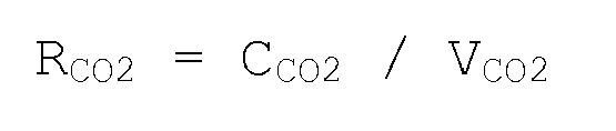
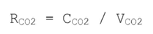
- the CO 2 recovery rate R CO2 is a setting value determined by the following formula when the volume of CO 2 contained in the exhaust gas G1 to be treated by the recovery device 10 is V CO2 and the volume of CO 2 to be recovered is C CO2 :
- R CO ⁇ 2 C CO ⁇ 2 / V CO ⁇ 2
- the recovery control unit 30 continues acquiring information on the actual flow rate (measurement value V G1 ) of the exhaust gas G1 discharged from the boiler 11, from the exhaust gas flow rate sensor 24 (Step S105 in Fig. 2 ). Additionally, the recovery control unit 30 continues acquiring information on the concentration (measurement value Y CO2 ) of CO 2 contained in the exhaust gas G1 discharged from the boiler 11, from the CO 2 concentration sensor 25 (Step S109 in Fig. 2 ).
- the computing unit 32 multiplies the measurement value V G1 acquired from the exhaust gas flow rate sensor 24 by the exhaust gas treatment rate R G1 set as a parameter, and sets the target flow rate of the exhaust gas G1 to be treated by CO 2 recovery device 10 (Step S107 in Fig. 2 ).
- the driving control unit 33 controls the opening degrees of the main valve 12 and the branch valve 16 (flow rate controller) on the basis of the setting value (Step S113 in Fig. 2 ).
- the main valve 12 is fully opened, whereas the branch valve 16 is fully closed. Then, even if the load of the power generation plant 40 fluctuates and the flow rate of the exhaust gas G1 discharged from the boiler 11 fluctuates, all the exhaust gas G1 is supplied to the absorption tower 13 through the flow channel F1.
- the exhaust gas treatment rate R G1 when the exhaust gas treatment rate R G1 is set to 50%, the volume of 50% of the measurement value V G1 is treated by the recovery device 10, and the remaining 50% is discharged from the system via the chimney 15. Therefore, for example, the opening degree of the main valve 12 is made to be 50%, whereas the opening degree of the branch valve 16 is made to be 50%. Then, even if the load of the power generation plant 40 fluctuates and the flow rate of the exhaust gas G1 discharged from the boiler 11 fluctuates, only 50% of the exhaust gas G1 is supplied to the absorption tower 13 through the flow channel F1. Thus, partial treatment of the exhaust gas is realized, maintaining the set exhaust gas treatment rate R G1 .
- the computing unit 32 performs multiplication of four values including the measurement value Y CO2 (CO 2 concentration in the exhaust gas) acquired from the CO 2 concentration sensor 25, the measurement value V G1 acquired from the exhaust gas flow rate sensor 24, and the exhaust gas treatment rate R G1 and the CO 2 recovery rate R CO2 that are set as parameters, and uses the resulting value as a target value of the volume of CO 2 to be treated and recovered by the recovery device 10 (Step S111 in Fig. 2 ). Moreover, the computing unit 32 calculates an absorbent circulation flow rate and a steam supply flow rate, which are the operation parameters of the recovery device 10, on the basis of this setting value.
- the absorbent circulation flow rate can be controlled by adjusting the rich solvent pump 17, the rich solvent valve 18, the lean solvent pump 20, and the lean solvent valve 21, and the steam supply flow rate can be controlled by adjusting the steam valve 23.
- the driving control unit 33 controls the volume of CO 2 to be recovered by adjusting the discharge volumes of the rich solvent pump 17 and the lean solvent pump 20 and the opening degrees of the rich solvent valve 18, the lean solvent valve 21, and the steam valve 23 on the basis of the absorbent circulation flow rate and the steam supply flow rate that are calculated by the computing unit 32 (Step S115 in Fig. 2 ).
- the aforementioned control procedure is continuously executed until there is a operation stop command of the power generation plant 40 (Step S116 in Fig. 2 ).
- the CO 2 recovery rate can be made to follow a constant rate, and the exhaust gas can be partially treated.
- a CO 2 recovery device 110 of a second embodiment is the same as that of the first embodiment except that the flow rate (measurement value V G1 ) of the exhaust gas G1 discharged from the boiler 11 and the concentration (measurement value Y CO2 ) of CO 2 contained in the exhaust gas is not measured, but is obtained by calculation. Accordingly, differences from the first embodiment will mainly be described below.
- the flow rate (measurement value Va) of combustion air and the flow rate (measurement value Vf) of fuel to be supplied to the boiler 11 are measured instead of the measurement value V G1 , and the total value (measurement value Vf + measurement value Va) of these values is used as an alternative value to the measurement value V G1 (the actual flow rate of the exhaust gas G1) of the first embodiment.
- setting values (a setting value Va and a setting value Vf) can also be used as alternative values of the measurement value Va and the measurement value Vf.
- the CO 2 concentration is obtained by calculating a gas composition after combustion, and is used as an alternative value of the measurement value Y CO2 of the first embodiment.
- the flow rate of the exhaust gas G1 can be directly obtained by measurement as in the first embodiment, and can be indirectly determined by calculation from the combustion air flow rate (the measurement value Va or the setting value Va) and the fuel flow rate (the measurement value Vf or the setting value Vf) as in second embodiment.
- the CO 2 concentration can be directly obtained by measurement as in the first embodiment, and can be obtained by calculation on the basis of the composition of the air and the fuel to be supplied as in the second embodiment. Since the exhaust gas actual flow rate and the CO 2 concentration that are obtained by calculation have sufficient precision as the alternative values of the exhaust gas flow rate and the CO 2 concentration obtained by measurement, the same effects as in the first embodiment can also be obtained in the second embodiment.
- a recovery device 120 of the third embodiment aims at improving the followability when the load of the boiler 11 that is an upstream facility fluctuates greatly. Therefore, the third embodiment uses a target value of power generation output control in the power generation plant 40 as a load command signal, and prepares table data in which the load command signal and the volume V CO2 of CO 2 contained in the exhaust gas G1 are matched.
- the table data as shown in Fig. 4 , is stored in the setting unit 31 of the recovery control unit 30.
- the table data is given as the following function, for example.
- V CO ⁇ 2 FA L SIG L SIG : Load command signal
- the recovery control unit 30 acquires the load command signal L SIG from the power generation plant 40.
- the computing unit 32 determines CO 2 target recovery volume (estimation value) on the basis of the following formulas.
- CO 2 target recovery volume FA L SIG x Exhaust gas treatment rate R G ⁇ 1 x CO 2 recovery rate R CO ⁇ 2
- the recovery device 120 uses the aforementioned estimation value as the volume of CO 2 to be recovered while the load of the boiler 11 fluctuates largely, and the first embodiment (second embodiment) may be applied apart from this. Therefore, the recovery device 120 adopts the following procedure.
- the recovery control unit 30 acquires a load setting value B1 of the boiler 11 and acquires a load measurement value B2 of the boiler 11 (Step S201 in Fig. 5 ).
- the load measurement values of the boiler 11 can be obtained by calculation from the fuel flow rate, the volume of steam generation, and the like.
- the recovery control unit 30 further obtains a difference ⁇ MW1 (absolute value) between the load setting value B1 and the load measurement value B2, and compares this difference ⁇ MW1 with a default value x (Step S203 in Fig. 5 ). If the difference ⁇ MW1 between the load setting value B1 and the load measurement value B2 is large, it is determined that the load of the boiler 11 fluctuates largely.
- ⁇ MW1 absolute value
- Step S101 of Fig. 2 the operation of the recovery device 10 is performed in the same procedure as in the first embodiment.
- the recovery control unit 30 specifies, on the basis of the acquired load command signal (Step S205 in Fig. 5 ), the volume V CO2 of CO 2 in the exhaust gas G1 from the table data (FA(L SIG )) (Step S207 in Fig. 5 ).
- Step S101 of Fig. 2 the operation of the recovery device 120 is performed in the same procedure as in the first embodiment.
- the table data FA (L SIG )
- Step S111 in Fig. 2 the calculation of the CO 2 target recovery volume
- the recovery device 10 according to the third embodiment includes the same effects as the first embodiment and can set the CO 2 target recovery volume in advance, the followability of the boiler 11 to load fluctuations is improved.
- the recovery device 10 uses a portion of steam generated by the power generation plant 40, more specifically, by the boiler 11, as a supply destination of steam required for the regeneration tower 14. Accordingly, when the volume of steam to be supplied to the regeneration tower 14 increases, there is a risk that the power generation capacity in the power generation plant 40 may be just as impaired. Therefore, in the fourth embodiment, the power generation capacity of the power generation plant 40 can be guaranteed by determining an upper limit of a CO 2 recovery volume capable of being recovered in the recovery device 130, that is, by setting a limit to the load of the recovery device 130 when required.
- the recovery control unit 30 of the fourth embodiment acquires the target value of the power generation output control as a load command signal B SIG of the boiler 11. Additionally, the recovery control unit 30 holds a maximum load B max of the boiler 11.
- the recovery control unit 30 obtains a difference ⁇ MW2 between the maximum load B max of the boiler 11 and the load command signal B SIG , in order to determine the remaining power of the boiler 11.
- the remaining power of the boiler 11 becomes larger as this difference is larger, and in contrast, the remaining power of the boiler 11 becomes smaller as the difference is smaller.
- the recovery device 130 determines the volume of CO 2 capable of being treated and recovered, according to this difference. Therefore, the recovery control unit 30 stores the table data, in which the difference and the volume of CO 2 capable of being recovered are matched, in the setting unit 31.
- the table data is given as the following function, for example.
- CO 2 ⁇ max FB MW ⁇ 2
- the recovery control unit 30 sets the obtained CO 2 volume to a recovery volume upper limit CO 2max by referring to the table data while obtaining the difference ⁇ MW2 serially. Also, the recovery control unit 30 of the fourth embodiment sets a limit so that the CO 2 recovery volume obtained in the first embodiment or the second embodiment does not exceed the recovery volume upper limit CO 2max .
- the recovery control unit 30 of the fourth embodiment operates the recovery device 10 in a procedure shown in Fig. 7 .
- the recovery control unit 30 acquires the load command signal B SIG from the power generation plant 40, and obtains the difference ⁇ MW2 from the maximum load B max of the boiler 11 that the recovery control unit holds (Steps S301 and 303 in Fig. 7 ).
- the recovery control unit 30 specifies CO 2max corresponding to the difference ⁇ MW2 obtained by referring to the table data (Step S305 in Fig. 7 ).
- the recovery control unit 30 compares the size of the target value C CO2 with the recovery volume upper limit CO 2max (Step S307 in Fig. 7 ). If the target value C CO2 is less than the upper limit CO 2max (Yes in Step S307 in Fig. 7 ), it is determined that the remaining power is in the boiler 11, and the absorbent circulation flow rate and the steam supply flow rate are controlled on the basis of the target value C CO2 (Step S309 in Fig. 7 ). If the target value C CO2 is equal to or greater than the upper limit CO 2max (No in S307 in Fig. 7 ), it is determined that there is no remaining power in the boiler 11, and the absorbent circulation flow rate and the steam supply flow rate are controlled on the basis of the upper limit CO 2max without adopting the target value C CO2 (Step S311 in Fig. 7 ).
- the same effects as in the first embodiment can be exhibited, and when priority is given to the power generation output, the setting value of the CO 2 target recovery volume can be automatically lowered. Additionally, even if the exhaust gas treatment rate is erroneously set to a high value, the power generation plant 40 can be operated without reducing the power generation output.
- the setting unit 31 of the recovery control unit 30 holds table data in which a boiler load command (a fuel flow rate setting value and an air flow rate setting value) B SIG and an absorbent circulation flow rate setting value C L are matched.
- the table data is given as the following function.
- C L FC B SIG
- the absorbent circulation flow rate setting value C L is obtained by multiplying the exhaust gas treatment rate by the CO 2 recovery rate.
- the absorbent circulation flow rate is controlled by adjusting the rich solvent pump 17, the rich solvent valve 18, or the like.
- the calculation of the CO 2 target recovery volume may use any method of the first embodiment to the third embodiment.
- the same effects as in the first embodiment are exhibited, and even if the flow rate of the exhaust gas G1 fluctuates abruptly, the followability of the boiler 11 to load fluctuations is improved by causing the absorbent circulation flow rate to fluctuate so as to follow the flow rate fluctuations. At this time, the CO 2 recovery rate in the absorption tower 13 does not decline.
- the rich solvent pump 17, the lean solvent pump 20, or the like is shown as means for controlling the circulation flow rate of the absorbent, and this is also an example and means that can control the circulation flow rate of the absorbent can be widely applied.
- a supply source of the steam for recovering the absorbent is not limited to the power generation plant 40 and can be individually provided.
Landscapes
- Engineering & Computer Science (AREA)
- Chemical & Material Sciences (AREA)
- Oil, Petroleum & Natural Gas (AREA)
- Analytical Chemistry (AREA)
- General Chemical & Material Sciences (AREA)
- Chemical Kinetics & Catalysis (AREA)
- Environmental & Geological Engineering (AREA)
- Health & Medical Sciences (AREA)
- Biomedical Technology (AREA)
- General Engineering & Computer Science (AREA)
- Mechanical Engineering (AREA)
- Combustion & Propulsion (AREA)
- Treating Waste Gases (AREA)
- Gas Separation By Absorption (AREA)
- Carbon And Carbon Compounds (AREA)
Abstract
Description
- The present invention relates to a CO2 recovery device that can cause a recovery rate to follow fluctuations of the volume of exhaust gas accompanied with fluctuations of the load of an apparatus located on an upstream side.
- In recent years, carbon dioxide (hereinafter referred to as CO2) is pointed out as one of causes of the global warming phenomenon. Therefore, a method of bringing a combustion gas of a boiler into contact with an absorbent and eliminating and recovering CO2 in the combustion gas, and a method of storing the recovered CO2 without discharging the CO2 to the atmospheric have been extensively studied for, for example, power generation facilities, such as a thermoelectric power plant that uses a large quantity of fossil fuels.
- CO2 recovery devices include, as basic constituent elements, an absorption tower that causes CO2 in gas to be absorbed into an absorbent, and a regeneration tower that separates CO2 from the absorbent. In order to properly operate the CO2 recovery devices, several proposals as shown below have been made up to now.
- The volume of exhaust gas required for attaining an objective is determined from a target CO2 recovery volume and CO2 concentration in the exhaust gas, and the exhaust gas is supplied to a CO2 recovery device (for example, PTL 1).
- The volume of exhaust gas from an exhaust gas source (a boiler or a gas turbine installed upstream of a CO2 recovery device) and CO2 concentration in the exhaust gas are measured, and operation parameters required for achieving a target CO2 recovery rate are determined (for example, PTL 2).
- The flow rate of the gas discharged to the atmosphere through a chimney without being treated by a CO2 recovery device, and the composition of this gas are measured using the gas from an exhaust gas source, and the volume of exhaust gas to be supplied to the CO2 recovery device is determined so as not to produce a stream that flows into the chimney from the atmosphere (for example, PTL 3).
-
- [PTL 1]: Japanese Unexamined Patent Application Publication No.
2011-527 - [PTL 2]: Japanese Unexamined Patent Application Publication No.
2011-528 - [PTL 3]: Japanese Unexamined Patent Application Publication No.
2010-17617 - Meanwhile, in PTL 1, an exhaust gas flow rate required to recover the target CO2 recovery volume is calculated, and the exhaust gas is sent into the CO2 recovery device. Therefore, when a constant rate of exhaust gas is treated in plants like power plants where load fluctuates, it is necessary to set target values every time in accordance with fluctuations of the target CO2 recovery volume.
- Additionally, in order to make CO2 emission reduction and cost compatible with each other, a CO2 device capable of treating a portion of the exhaust gas and recovering CO2 (partial treatment) is expected. However, the proposals of PTLs 2 and 3 merely show a method of controlling the volume of the exhaust gas in a case when all the exhaust gas is drawn into the CO2 recovery device, and this proposal cannot cope with the partial treatment of the exhaust gas that treats a portion of the exhaust gas.
- The invention has been made on the basis of such technical problems, and an object thereof is to provide a CO2 recovery device that can cause the recovery rate of CO2 to follow a constant rate and can partially treat exhaust gas, even if the load on an upstream side fluctuates and the volume of the exhaust gas fluctuates.
- A CO2 recovery device of the invention includes a CO2 absorption tower that brings an exhaust gas containing CO2 into contact with an absorbent to eliminate CO2 in the exhaust gas; and a regeneration tower that eliminates and regenerates CO2 in a rich solution that has absorbed CO2 in the CO2 absorption tower, and the absorbent, which is a lean solution from which CO2 is eliminated in the regeneration tower, is reused in the CO2 absorption tower.
- The CO2 recovery device of the invention sets an exhaust gas treatment rate RG1 and a CO2 recovery rate RCO2 shown below as operation parameters of the CO2 recovery device.
- A target treatment volume for exhaust gas to be treated by the CO2 recovery device is specified on the basis of the product of an actual flow rate of the exhaust gas discharged toward the CO2 recovery device from a generation source of the exhaust gas, and the exhaust gas treatment rate RG1.
- Additionally, a target recovery volume for CO2 to be recovered by the CO2 recovery device is specified on the basis of the product of an actual volume of CO2 contained in the exhaust gas discharged from the generation source of the exhaust gas to the CO2 recovery device, the exhaust gas treatment rate RG1, and the CO2 recovery rate RCO2.

- VG1: Flow rate of exhaust gas discharged from generation source of exhaust gas
- TCO2: Volume of exhaust gas to be treated by CO2 recovery device
- VCO2: Volume of CO2 contained in exhaust gas to be treated by CO2 recovery device
- CCO2 : Volume of CO2 to be recovered by CO2 recovery device
- In CO2 recovery device of the invention, the actual flow rate of the exhaust gas and the actual volume of CO2 contained in the exhaust gas can be directly obtained by measuring the exhaust gas. Additionally, the actual flow rate of the exhaust gas can be indirectly obtained by calculation based on a flow rate of fuel and a flow rate of combustion gas to be supplied to the generation source of the exhaust gas, and the actual volume of CO2 contained in the exhaust gas can be indirectly obtained by calculation on the basis of the flow rates and composition of the fuel and the combustion gas.
- In the CO2 recovery device of the invention, preferably, if a load of the generation source of the exhaust gas fluctuates beyond a predetermined value, the actual flow rate of the exhaust gas is obtained by collating data in which a load to the generation source of the exhaust gas and the flow rate of the exhaust gas are matched, with a load command signal to the generation source of the exhaust gas, and the target recovery volume of the CO2 is specified.
- Then, the followability to load fluctuations is improved.
- In the CO2 recovery device of the invention, an upper limit can be set to the recovery volume of CO2 on the basis of the load of the generation source of exhaust gas.
- When, for example, the steam to be consumed in an upstream plant is used for a power source of the CO2 recovery device, if the volume of the steam to be consumed by the CO2 recovery device increases too much, there is a concern that the volume of the steam that can be consumed by the upstream plant is just as scarce. Therefore, the volume of the steam to be consumed by the CO2 recovery device is limited by setting an upper limit to the CO2 recovery volume in the CO2 recovery device.
- In the CO2 recovery device of the invention, a target value of an absorbent circulation flow rate can be set on the basis of the load of the generation source of the exhaust gas.
- Then, even if the exhaust gas flow rate fluctuates abruptly, the load followability can be improved by fluctuating the absorbent circulation flow rate so as to follow this flow rate.
- According to the invention, provided is a CO2 recovery device that can cause the recovery rate of CO2 to follow a constant rate and can partially treat exhaust gas, even if the load on an upstream side fluctuates and the volume of the exhaust gas fluctuates.
-
-
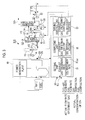
Fig. 1 is a view showing the configuration of a CO2 recovery device according to a first embodiment. -
Fig. 2 is a flow view showing a control procedure of the CO2 recovery device according to the first embodiment. -
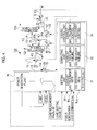
Fig. 3 is a view showing the configuration of a CO2 recovery device according to a second embodiment. -
Fig. 4 is a view showing the configuration of a CO2 recovery device according to a third embodiment. -
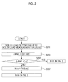
Fig. 5 is a flow view showing a control procedure of the CO2 recovery device according to the third embodiment. -
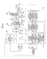
Fig. 6 is a view showing the configuration of a CO2 recovery device according to a fourth embodiment. -
Fig. 7 is a flow view showing a control procedure of the CO2 recovery device according to the fourth embodiment. -
Fig. 8 is a view showing the configuration of a CO2 recovery device according to a fifth embodiment. - Although several embodiments of the invention will be described below, the basic configuration of a CO2 recovery device to be applied is the same in any embodiment. Therefore, the CO2 recovery device will first be described.
- As shown in
Fig. 1 , the CO2 recovery device (hereinafter simply referred to as a recovery device) 10 includes, for example, anabsorption tower 13 that brings exhaust gas G1 containing CO2 and O2, which are discharged from aboiler 11 constituting apower generation plant 40 using fossil fuels, into contact with an absorbent AL, to eliminate CO2 from the exhaust gas G1, and aregeneration tower 14 that discharges CO2 from a rich solution RL that is the absorbent that has absorbed CO2, to regenerate the absorbent AL, as main constituent elements. In therecovery device 10, a lean solution RAL that is the regenerated absorbent from which CO2 has been eliminated by theregeneration tower 14 is reused as absorbent AL by theabsorption tower 13. - Additionally, the
recovery device 10 includes arecovery control unit 30. Therecovery control unit 30 functions so as to cause the recovery rate of CO2 to follow a constant rate and realize partial treatment of the exhaust gas, even if the load of thepower generation plant 40 located on an upstream side fluctuates and the volume of the exhaust gas fluctuates. - In the
recovery device 10, the exhaust gas G1 containing CO2 from theboiler 11 is sent to theabsorption tower 13 through a flow channel F1 that connects theboiler 11 and theabsorption tower 13. A main valve 12 that adjusts the volume of the exhaust gas G1 to be supplied to theabsorption tower 13 is provided on the flow channel F1. - A flow channel F2 branches from the flow channel F1, and a tip of the flow channel F2 where the
branch valve 16 is provided is connected to achimney 15. When a portion in the exhaust gas G1 discharged from theboiler 11 is sent from a system without being sent to theabsorption tower 13, the exhaust gas G1 is discharged from thechimney 15 via the flow channel F2. Thebranch valve 16 adjusts the volume of discharge of the exhaust gas G1 from thechimney 15. - An exhaust gas
flow rate sensor 24 that measures the flow rate (actual exhaust gas flow rate or measurement value VG1) of the whole exhaust gas G1 discharged from theboiler 11, and a CO2 concentration sensor 25 that measures the concentration (measurement value YCO2) of CO2 contained in the exhaust gas G1 are provided on the flow channel F1. The information (measurement value VG1, measurement value YCO2) measured by the exhaust gasflow rate sensor 24 and the CO2 concentration sensor 25 is continuously transmitted to therecovery control unit 30 during the operation of thepower generation plant 40 and theboiler 11. The actual volume of CO2 contained in the exhaust gas G1 can be obtained by multiplying the measurement value VG1 by the measurement value YCO2. - In addition, the invention does not hinder providing other elements, such as a blower that raises the pressure of the exhaust gas, a cooling tower that cools the exhaust gas G1, and a denitration/desulfurization facility, between the
boiler 11 and theabsorption tower 13. - In the
absorption tower 13, the exhaust gas G1 comes into countercurrent contact with the absorbent AL having, for example, an amine-based solution as a base, and CO2 in the exhaust gas G1 is absorbed into the absorbent AL by a chemical reaction. In contrast, the exhaust gas G2 after CO2 has been eliminated comes into vapor-liquid contact with condensed water containing the absorbent AL supplied to theabsorption tower 13, and the absorbent AL accompanied with the exhaust gas G2 is recovered, and is then discharged from the system. - Additionally, the rich solution RL that has absorbed CO2 is raised in pressure by a rich
solvent pump 17, is heated by the lean solution RAL, which is the absorbent regenerated by theregeneration tower 14, in a rich/leansolvent heat exchanger 19 via a richsolvent valve 18, and is supplied to theregeneration tower 14. Theabsorption tower 13 and theregeneration tower 14 are connected by a flow channel F3, and the richsolvent pump 17, the richsolvent valve 18, and the rich/leansolvent heat exchanger 19 are provided in order from theabsorption tower 13 side in the flow channel F3. The rich solution RL that has absorbed CO2 is supplied to theregeneration tower 14 through the flow channel F3. - The rich solution RL discharged from an upper portion of the
regeneration tower 14 to the inside thereof causes an endothermic reaction, and discharges a large portion of CO2. The absorbent that has discharged a portion or a large portion of CO2 within theregeneration tower 14 is referred to as a semi-lean solution RAL. When the semi-lean solution RAL reaches the lower portion of theregeneration tower 14, the solution is turned into the absorbent from which almost all CO2 has been eliminated, that is, a lean solution RAL. The lean solution RAL is superheated with steam S by theregeneration superheater 22, and is supplied to the inside of theregeneration tower 14 as steam. The steam S supplied to theregeneration superheater 22 is circulated, for example, between the regeneration superheater and thepower generation plant 40. Also, the supply volume of the steam S supplied to theregeneration superheater 22 is controlled by asteam valve 23 provided on a flow channel F5. - Meanwhile, CO2 gas (CO2) accompanied with the steam, which is discharged from the rich solution RL and the semi-lean solution RAL within the regeneration tower, is drawn from a top portion of the
regeneration tower 14. The CO2 gas is discharged from the system and separately recovered after steam is condensed, for example by a condenser, and water is separated by a separation drum. The recovered CO2 gas is pressed into an oil field on the basis of an enhanced oil recovery (EOR) method, or is stored in a water bearing stratum to establish global warming countermeasures. In addition, the separated water is supplied to the upper portion of theregeneration tower 14. - The regenerated absorbent (lean solution RAL) is pumped by a lean
solvent pump 20, and is sent toward the rich/leansolvent heat exchanger 19 via a leansolvent valve 21. Also, the lean solution RAL is supplied to theabsorption tower 13 after being cooled by the rich solution RL in the rich/leansolvent heat exchanger 19. Theregeneration tower 14 and theabsorption tower 13 are connected by a flow channel F4, and the leansolvent pump 20, the leansolvent valve 21, and the rich/leansolvent heat exchanger 19 are provided in order from theregeneration tower 14 side in the flow channel F4. The lean solution RAL is returned to theabsorption tower 13 through the flow channel F4. - By repeating a series of the aforementioned cycles, the
recovery device 10 recovers CO2 continuously from the exhaust gas G1 discharged from theboiler 11. In this process, therecovery control unit 30 adjusts the opening degrees of the main valve 12 and thebranch valve 16 to control the volume (exhaust gas treatment rate) of the exhaust gas G1 to be treated by therecovery device 10. Additionally, therecovery control unit 30 adjusts the operation and opening degrees of the richsolvent pump 17, the richsolvent valve 18, the leansolvent pump 20, the leansolvent valve 21, and thesteam valve 23 to control the volume (CO2 recovery volume) of CO2 to be recovered by theabsorption tower 13 and theregeneration tower 14. The first embodiment to fifth embodiment to be described below have respective features in these control contents. However, all the embodiments are common in that causing the exhaust gas recovery rate to follow a constant rate and partially treating the exhaust gas can be achieved, even if an exhaust gas flow rate fluctuates as the load of thepower generation plant 40 on the upstream side of therecovery device 10 fluctuates. - The configuration of the
power generation plant 40 is arbitrary, and the power generation plant may include a high-pressure turbine that is driven by drawing the steam generated by theboiler 11, an intermediate-pressure turbine that is driven by drawing reheated steam returned from the high-pressure turbine and heated again by theboiler 11, a low-pressure turbine that draws and drives the steam decompressed by generating power by the intermediate-pressure turbine, and a condenser that condenses the steam decompressed by generating power with the low-pressure turbine. - The
recovery control unit 30 according to a first embodiment, as shown inFig. 1 , includes asetting unit 31 that sets operation parameters and the other parameters, acomputing unit 32, and a drivingcontrol unit 33. Hereinafter, also refer toFig. 2 . - An exhaust gas treatment rate RG1 and a CO2 recovery rate RCO2 as the operation parameters are input to and set in the setting unit 31 (Steps S101 and 103 in
Fig. 2 ). - The exhaust gas treatment rate RG1 is a setting value determined by the following formula when the flow rate of the exhaust gas G1 discharged from the
boiler 11 is VG1 and the volume of the exhaust gas G1 to be treated by therecovery device 10 is TCO2.
- Additionally, the CO2 recovery rate RCO2 is a setting value determined by the following formula when the volume of CO2 contained in the exhaust gas G1 to be treated by the
recovery device 10 is VCO2 and the volume of CO2 to be recovered is CCO2 :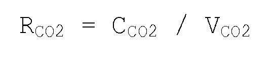
- The
recovery control unit 30 continues acquiring information on the actual flow rate (measurement value VG1) of the exhaust gas G1 discharged from theboiler 11, from the exhaust gas flow rate sensor 24 (Step S105 inFig. 2 ). Additionally, therecovery control unit 30 continues acquiring information on the concentration (measurement value YCO2) of CO2 contained in the exhaust gas G1 discharged from theboiler 11, from the CO2 concentration sensor 25 (Step S109 inFig. 2 ). - In the
recovery control unit 30, thecomputing unit 32 multiplies the measurement value VG1 acquired from the exhaust gasflow rate sensor 24 by the exhaust gas treatment rate RG1 set as a parameter, and sets the target flow rate of the exhaust gas G1 to be treated by CO2 recovery device 10 (Step S107 inFig. 2 ). The drivingcontrol unit 33 controls the opening degrees of the main valve 12 and the branch valve 16 (flow rate controller) on the basis of the setting value (Step S113 inFig. 2 ). - For example, when the exhaust gas treatment rate RG1 is set to 100%, in order to treat the whole volume of the measurement value VG1 with the
recovery device 10, the main valve 12 is fully opened, whereas thebranch valve 16 is fully closed. Then, even if the load of thepower generation plant 40 fluctuates and the flow rate of the exhaust gas G1 discharged from theboiler 11 fluctuates, all the exhaust gas G1 is supplied to theabsorption tower 13 through the flow channel F1. - Additionally, for example, when the exhaust gas treatment rate RG1 is set to 50%, the volume of 50% of the measurement value VG1 is treated by the
recovery device 10, and the remaining 50% is discharged from the system via thechimney 15. Therefore, for example, the opening degree of the main valve 12 is made to be 50%, whereas the opening degree of thebranch valve 16 is made to be 50%. Then, even if the load of thepower generation plant 40 fluctuates and the flow rate of the exhaust gas G1 discharged from theboiler 11 fluctuates, only 50% of the exhaust gas G1 is supplied to theabsorption tower 13 through the flow channel F1. Thus, partial treatment of the exhaust gas is realized, maintaining the set exhaust gas treatment rate RG1. - Additionally, in the
recovery control unit 30, thecomputing unit 32 performs multiplication of four values including the measurement value YCO2 (CO2 concentration in the exhaust gas) acquired from the CO2 concentration sensor 25, the measurement value VG1 acquired from the exhaust gasflow rate sensor 24, and the exhaust gas treatment rate RG1 and the CO2 recovery rate RCO2 that are set as parameters, and uses the resulting value as a target value of the volume of CO2 to be treated and recovered by the recovery device 10 (Step S111 inFig. 2 ). Moreover, thecomputing unit 32 calculates an absorbent circulation flow rate and a steam supply flow rate, which are the operation parameters of therecovery device 10, on the basis of this setting value. Here, the absorbent circulation flow rate can be controlled by adjusting the richsolvent pump 17, the richsolvent valve 18, the leansolvent pump 20, and the leansolvent valve 21, and the steam supply flow rate can be controlled by adjusting thesteam valve 23. Accordingly, the drivingcontrol unit 33 controls the volume of CO2 to be recovered by adjusting the discharge volumes of the richsolvent pump 17 and the leansolvent pump 20 and the opening degrees of the richsolvent valve 18, the leansolvent valve 21, and thesteam valve 23 on the basis of the absorbent circulation flow rate and the steam supply flow rate that are calculated by the computing unit 32 (Step S115 inFig. 2 ). - The aforementioned control procedure is continuously executed until there is a operation stop command of the power generation plant 40 (Step S116 in
Fig. 2 ). - As described above, according to the first embodiment, even if the load of the
boiler 11 that is an apparatus on the upstream side of therecovery device 10 fluctuates, and the flow rate of the exhaust gas G1 fluctuate, the CO2 recovery rate can be made to follow a constant rate, and the exhaust gas can be partially treated. - A CO2 recovery device 110 of a second embodiment is the same as that of the first embodiment except that the flow rate (measurement value VG1) of the exhaust gas G1 discharged from the
boiler 11 and the concentration (measurement value YCO2) of CO2 contained in the exhaust gas is not measured, but is obtained by calculation. Accordingly, differences from the first embodiment will mainly be described below. - In the second embodiment, as shown in
Fig. 3 , the flow rate (measurement value Va) of combustion air and the flow rate (measurement value Vf) of fuel to be supplied to theboiler 11 are measured instead of the measurement value VG1, and the total value (measurement value Vf + measurement value Va) of these values is used as an alternative value to the measurement value VG1 (the actual flow rate of the exhaust gas G1) of the first embodiment. - Alternatively, since the combustion air and the fuel to be supplied to the
boiler 11 are usually set in advance, setting values (a setting value Va and a setting value Vf) can also be used as alternative values of the measurement value Va and the measurement value Vf. - Additionally, in the second embodiment, as shown in
Fig. 3 , when the composition of the fuel and the air to be supplied to theboiler 11 is known, the CO2 concentration is obtained by calculating a gas composition after combustion, and is used as an alternative value of the measurement value YCO2 of the first embodiment. - As described above, the flow rate of the exhaust gas G1 can be directly obtained by measurement as in the first embodiment, and can be indirectly determined by calculation from the combustion air flow rate (the measurement value Va or the setting value Va) and the fuel flow rate (the measurement value Vf or the setting value Vf) as in second embodiment. Similarly, the CO2 concentration can be directly obtained by measurement as in the first embodiment, and can be obtained by calculation on the basis of the composition of the air and the fuel to be supplied as in the second embodiment. Since the exhaust gas actual flow rate and the CO2 concentration that are obtained by calculation have sufficient precision as the alternative values of the exhaust gas flow rate and the CO2 concentration obtained by measurement, the same effects as in the first embodiment can also be obtained in the second embodiment.
- In addition, there is an advantage that the actual flow rate of the exhaust gas G1 from the
boiler 11 that is generally difficult to be precisely measured can be obtained in the second embodiment from the air flow rate and the fuel flow rate that are relatively easily measured. The same applies for the concentration of CO2 contained in the exhaust gas G1 from theboiler 11, and the composition of the exhaust gas from theboiler 11 can be relatively easily obtained by calculation from fuel and air from which it is difficult to continuously measure the CO2 concentration and that has an almost constant composition. - A
recovery device 120 of the third embodiment aims at improving the followability when the load of theboiler 11 that is an upstream facility fluctuates greatly. Therefore, the third embodiment uses a target value of power generation output control in thepower generation plant 40 as a load command signal, and prepares table data in which the load command signal and the volume VCO2 of CO2 contained in the exhaust gas G1 are matched. The table data, as shown inFig. 4 , is stored in thesetting unit 31 of therecovery control unit 30. The table data is given as the following function, for example.
- As for the
recovery device 120, therecovery control unit 30 acquires the load command signal LSIG from thepower generation plant 40. Therecovery control unit 30 specifies CO2 volume (VCO2 = FA (LSIG)) by referring to the aforementioned table data while acquiring the load command signal LSIG. Then, thecomputing unit 32 determines CO2 target recovery volume (estimation value) on the basis of the following formulas.
- The
recovery device 120 according to the third embodiment uses the aforementioned estimation value as the volume of CO2 to be recovered while the load of theboiler 11 fluctuates largely, and the first embodiment (second embodiment) may be applied apart from this. Therefore, therecovery device 120 adopts the following procedure. - As shown in
Figs. 4 and5 , therecovery control unit 30 acquires a load setting value B1 of theboiler 11 and acquires a load measurement value B2 of the boiler 11 (Step S201 inFig. 5 ). In addition, the load measurement values of theboiler 11 can be obtained by calculation from the fuel flow rate, the volume of steam generation, and the like. - The
recovery control unit 30 further obtains a difference ΔMW1 (absolute value) between the load setting value B1 and the load measurement value B2, and compares this difference ΔMW1 with a default value x (Step S203 inFig. 5 ). If the difference ΔMW1 between the load setting value B1 and the load measurement value B2 is large, it is determined that the load of theboiler 11 fluctuates largely. - If the difference is less than the default value x, the processing proceeds to Step S101 of
Fig. 2 . In the following steps, the operation of therecovery device 10 is performed in the same procedure as in the first embodiment. - In contrast, if the difference is equal to or greater than the default value x, the
recovery control unit 30 specifies, on the basis of the acquired load command signal (Step S205 inFig. 5 ), the volume VCO2 of CO2 in the exhaust gas G1 from the table data (FA(LSIG)) (Step S207 inFig. 5 ). - Thereafter, the processing proceeds to Step S101 of
Fig. 2 , and the operation of therecovery device 120 is performed in the same procedure as in the first embodiment. However, the table data (FA (LSIG)) is used instead of the calculation of the CO2 target recovery volume (Step S111 inFig. 2 ). - As described above, since the
recovery device 10 according to the third embodiment includes the same effects as the first embodiment and can set the CO2 target recovery volume in advance, the followability of theboiler 11 to load fluctuations is improved. - The
recovery device 10 uses a portion of steam generated by thepower generation plant 40, more specifically, by theboiler 11, as a supply destination of steam required for theregeneration tower 14. Accordingly, when the volume of steam to be supplied to theregeneration tower 14 increases, there is a risk that the power generation capacity in thepower generation plant 40 may be just as impaired. Therefore, in the fourth embodiment, the power generation capacity of thepower generation plant 40 can be guaranteed by determining an upper limit of a CO2 recovery volume capable of being recovered in therecovery device 130, that is, by setting a limit to the load of therecovery device 130 when required. - Therefore, the
recovery control unit 30 of the fourth embodiment, as shown inFig. 6 , acquires the target value of the power generation output control as a load command signal BSIG of theboiler 11. Additionally, therecovery control unit 30 holds a maximum load Bmax of theboiler 11. - For example, if the value of power generation output becomes close to the maximum load Bmax of the
boiler 11, it can be said that the remaining power that can be allocated to therecovery device 130 from the load of theboiler 11 is small. Thus, therecovery control unit 30 obtains a difference ΔMW2 between the maximum load Bmax of theboiler 11 and the load command signal BSIG, in order to determine the remaining power of theboiler 11. The remaining power of theboiler 11 becomes larger as this difference is larger, and in contrast, the remaining power of theboiler 11 becomes smaller as the difference is smaller. Then, therecovery device 130 determines the volume of CO2 capable of being treated and recovered, according to this difference. Therefore, therecovery control unit 30 stores the table data, in which the difference and the volume of CO2 capable of being recovered are matched, in thesetting unit 31. The table data is given as the following function, for example.
- The
recovery control unit 30 sets the obtained CO2 volume to a recovery volume upper limit CO2max by referring to the table data while obtaining the difference ΔMW2 serially. Also, therecovery control unit 30 of the fourth embodiment sets a limit so that the CO2 recovery volume obtained in the first embodiment or the second embodiment does not exceed the recovery volume upper limit CO2max. - The
recovery control unit 30 of the fourth embodiment operates therecovery device 10 in a procedure shown inFig. 7 . - The
recovery control unit 30 acquires the load command signal BSIG from thepower generation plant 40, and obtains the difference ΔMW2 from the maximum load Bmax of theboiler 11 that the recovery control unit holds (Steps S301 and 303 inFig. 7 ). - Next, the
recovery control unit 30 specifies CO2max corresponding to the difference ΔMW2 obtained by referring to the table data (Step S305 inFig. 7 ). - Next, the
recovery control unit 30 compares the size of the target value CCO2 with the recovery volume upper limit CO2max (Step S307 inFig. 7 ). If the target value CCO2 is less than the upper limit CO2max (Yes in Step S307 inFig. 7 ), it is determined that the remaining power is in theboiler 11, and the absorbent circulation flow rate and the steam supply flow rate are controlled on the basis of the target value CCO2 (Step S309 inFig. 7 ). If the target value CCO2 is equal to or greater than the upper limit CO2max (No in S307 inFig. 7 ), it is determined that there is no remaining power in theboiler 11, and the absorbent circulation flow rate and the steam supply flow rate are controlled on the basis of the upper limit CO2max without adopting the target value CCO2 (Step S311 inFig. 7 ). - As described above, according to the fourth embodiment, the same effects as in the first embodiment can be exhibited, and when priority is given to the power generation output, the setting value of the CO2 target recovery volume can be automatically lowered. Additionally, even if the exhaust gas treatment rate is erroneously set to a high value, the
power generation plant 40 can be operated without reducing the power generation output. - In a
recovery device 140 of a fifth embodiment, the settingunit 31 of therecovery control unit 30 holds table data in which a boiler load command (a fuel flow rate setting value and an air flow rate setting value) BSIG and an absorbent circulation flow rate setting value CL are matched. The table data is given as the following function.
- The
recovery control unit 30, as shown inFig. 8 , acquires the boiler load command BSIG, refers to the table data (CL = FC(BSIG)) of thesetting unit 31 to thereby specify the absorbent circulation flow rate setting value CL, and performs a control so that an actual absorbent circulation flow rate reaches the setting value. It is noted herein that the absorbent circulation flow rate setting value CL is obtained by multiplying the exhaust gas treatment rate by the CO2 recovery rate. The absorbent circulation flow rate is controlled by adjusting the richsolvent pump 17, the richsolvent valve 18, or the like. The calculation of the CO2 target recovery volume may use any method of the first embodiment to the third embodiment. - According to the fifth embodiment, the same effects as in the first embodiment are exhibited, and even if the flow rate of the exhaust gas G1 fluctuates abruptly, the followability of the
boiler 11 to load fluctuations is improved by causing the absorbent circulation flow rate to fluctuate so as to follow the flow rate fluctuations. At this time, the CO2 recovery rate in theabsorption tower 13 does not decline. - In the aforementioned embodiments, the example in which the CO2 generated by the
boiler 11 of thepower generation plant 40 is recovered has been described. However, the target of the invention is not limited to this, and the invention can also be applied to arbitrary apparatuses and facilities that generate CO2. - Additionally, the rich
solvent pump 17, the leansolvent pump 20, or the like is shown as means for controlling the circulation flow rate of the absorbent, and this is also an example and means that can control the circulation flow rate of the absorbent can be widely applied. - Additionally, a supply source of the steam for recovering the absorbent is not limited to the
power generation plant 40 and can be individually provided. - In addition to this, the configurations mentioned in the aforementioned embodiments can be selected or can be appropriately changed to other configurations so long as the configurations do not depart from the concept of the invention.
-
- G1, G2:
- exhaust gas
- 10, 110, 120, 130, 140:
- CO2 recovery device
- 11:
- boiler
- 12:
- main valve
- 13:
- absorption tower
- 14:
- regeneration tower
- 15:
- chimney
- 16:
- branch valve
- 17:
- rich solvent pump
- 18:
- rich solvent valve
- 19:
- rich/lean solvent heat exchanger
- 20:
- lean solvent pump
- 21:
- lean solvent valve
- 22:
- regeneration superheater
- 23:
- steam valve
- 24:
- exhaust gas flow rate sensor
- 25:
- CO2 concentration sensor
- 30:
- recovery control unit
- 31:
- parameter setting unit
- 32:
- computing unit
- 33:
- driving control unit
- 40:
- power generation plant
Claims (6)
- A CO2 recovery device comprising:a CO2 absorption tower that brings an exhaust gas containing CO2 into contact with an absorbent to eliminate CO2 in the exhaust gas; anda regeneration tower that eliminates and regenerates CO2 in a rich solution that has absorbed CO2 in the CO2 absorption tower,wherein the absorbent, which is a lean solution from which CO2 is eliminated in the regeneration tower, is reused in the CO2 absorption tower,wherein an exhaust gas treatment rate RG1 and a CO2 recovery rate RCO2 shown below are set as operation parameters of the CO2 recovery device,wherein a target treatment volume for exhaust gas to be treated by the CO2 recovery device is specified on the basis of the product of an actual flow rate of the exhaust gas discharged toward the CO2 recovery device from a generation source of the exhaust gas, and the exhaust gas treatment rate RG1, andwherein a target recovery volume for CO2 to be recovered by the CO2 recovery device is specified on the basis of the product of an actual volume of CO2 contained in the exhaust gas discharged from the generation source of the exhaust gas to the CO2 recovery device, the exhaust gas treatment rate RG1, and the CO2 recovery rate RCO2.
 VG1: Flow rate of exhaust gas discharged from generation source of exhaust gasTCO2: Volume of exhaust gas to be treated by CO2 recovery device
 VCO2: Volume of CO2 contained in exhaust gas to be treated by CO2 recovery deviceCCO2 : Volume of CO2 to be recovered by CO2 recovery device
 - The CO2 recovery device according to Claim 1,
wherein the actual flow rate of the exhaust gas discharged toward the CO2 recovery device and the actual volume of CO2 contained in the exhaust gas are obtained by measuring the exhaust gas. - The CO2 recovery device according to Claim 1,
wherein the actual flow rate of the exhaust gas is obtained by calculation on the basis of a flow rate of fuel and a flow rate of combustion gas to be supplied to the generation source of the exhaust gas, and
wherein the actual volume of CO2 contained in the exhaust gas is obtained by calculation on the basis of the flow rates and composition of the fuel and the combustion gas. - The CO2 recovery device according to Claim 1,
wherein if a load of the generation source of the exhaust gas fluctuates beyond a predetermined value, the actual flow rate of the exhaust gas is obtained by collating data in which a load to the generation source of the exhaust gas and the flow rate of the exhaust gas are matched, with a load command signal to the generation source of the exhaust gas, and the recovery volume of the CO2 is specified. - The CO2 recovery device according to Claim 1,
wherein an upper limit of the recovery volume of the CO2 is set on the basis of the load of the generation source of the exhaust gas. - The CO2 recovery device according to Claim 1,
wherein a target value of an absorbent circulation flow rate is set on the basis of the load of the generation source of the exhaust gas.
Applications Claiming Priority (2)
| Application Number | Priority Date | Filing Date | Title |
|---|---|---|---|
| JP2012021940A JP6216490B2 (en) | 2012-02-03 | 2012-02-03 | CO2 recovery device |
| PCT/JP2012/006940 WO2013114488A1 (en) | 2012-02-03 | 2012-10-30 | Co2 recovery device |
Publications (3)
| Publication Number | Publication Date |
|---|---|
| EP2821121A1 true EP2821121A1 (en) | 2015-01-07 |
| EP2821121A4 EP2821121A4 (en) | 2015-10-28 |
| EP2821121B1 EP2821121B1 (en) | 2018-08-15 |
Family
ID=48904578
Family Applications (1)
| Application Number | Title | Priority Date | Filing Date |
|---|---|---|---|
| EP12867698.8A Active EP2821121B1 (en) | 2012-02-03 | 2012-10-30 | Co2 recovery device |
Country Status (4)
| Country | Link |
|---|---|
| US (1) | US9186620B2 (en) |
| EP (1) | EP2821121B1 (en) |
| JP (1) | JP6216490B2 (en) |
| WO (1) | WO2013114488A1 (en) |
Cited By (4)
| Publication number | Priority date | Publication date | Assignee | Title |
|---|---|---|---|---|
| EP3150270A4 (en) * | 2014-07-10 | 2017-06-14 | Mitsubishi Heavy Industries, Ltd. | Co2 recovery device and co2 recovery method |
| US10566078B1 (en) | 2018-09-19 | 2020-02-18 | Basf Se | Method of Determination of Operating and/or Dimensioning Parameters of A Gas Treatment Plant |
| WO2020058202A1 (en) * | 2018-09-19 | 2020-03-26 | Basf Se | Modelling of operating and/or dimensioning parameters of a gas treatment plant |
| US12282722B2 (en) | 2018-09-19 | 2025-04-22 | Basf Se | Simulation of unit operations of a chemical plant for acid gas removal |
Families Citing this family (14)
| Publication number | Priority date | Publication date | Assignee | Title |
|---|---|---|---|---|
| JP6200338B2 (en) * | 2014-01-24 | 2017-09-20 | 三菱重工業株式会社 | CO2 recovery device and CO2 recovery method |
| JP6325376B2 (en) * | 2014-07-10 | 2018-05-16 | 三菱重工業株式会社 | CO2 recovery device and CO2 recovery method |
| JP6280475B2 (en) * | 2014-09-22 | 2018-02-14 | 株式会社東芝 | Carbon dioxide separation and recovery apparatus and operation control method thereof |
| JP2016187796A (en) * | 2015-03-30 | 2016-11-04 | 新日鉄住金エンジニアリング株式会社 | Carbon dioxide manufacturing facility and carbon dioxide manufacturing method |
| JP6297006B2 (en) * | 2015-03-30 | 2018-03-20 | 新日鉄住金エンジニアリング株式会社 | Carbon dioxide production facility and carbon dioxide production method |
| WO2018074443A1 (en) | 2016-10-19 | 2018-04-26 | 三菱重工業株式会社 | Carbon dioxide recovery system, thermal power generation facility, and method for recovering carbon dioxide |
| AU2018308959B2 (en) * | 2018-02-20 | 2020-08-13 | Mitsubishi Heavy Industries, Ltd. | Exhaust gas treatment device and exhaust gas treatment method |
| AU2018308960B2 (en) | 2018-02-20 | 2020-08-20 | Mitsubishi Heavy Industries, Ltd. | Exhaust gas treatment device and exhaust gas treatment method |
| JP7013322B2 (en) * | 2018-05-16 | 2022-01-31 | 株式会社東芝 | Carbon dioxide capture system and its operation method |
| JP7251720B2 (en) * | 2018-06-19 | 2023-04-04 | ヤンマーパワーテクノロジー株式会社 | Carbon dioxide capture system |
| JP7576975B2 (en) * | 2020-12-24 | 2024-11-01 | 日鉄エンジニアリング株式会社 | Carbon dioxide gas recovery device and carbon dioxide gas recovery method |
| JP7801102B2 (en) * | 2021-07-15 | 2026-01-16 | 三菱重工業株式会社 | CO2 capture device control device |
| US20230166212A1 (en) * | 2021-11-30 | 2023-06-01 | University Of Kentucky Research Foundation | Automated co2 capture process control system with solvent property prediction |
| US20250032973A1 (en) * | 2023-07-26 | 2025-01-30 | Mitsubishi Heavy Industries, Ltd. | Co2 recovery device |
Family Cites Families (9)
| Publication number | Priority date | Publication date | Assignee | Title |
|---|---|---|---|---|
| GB2100471B (en) * | 1981-05-28 | 1985-03-06 | British Gas Corp | Automatic coi removal system and operation thereof |
| US5085839A (en) * | 1990-01-08 | 1992-02-04 | Lyondell Petrochemical Company | Apparatus for the prevention of acid gas excursions |
| US6066304A (en) * | 1998-08-06 | 2000-05-23 | Delores Pircon | Process for removing sulfur dioxide out of a gas |
| US7247279B2 (en) * | 2000-08-01 | 2007-07-24 | Enviroscrub Technologies Corporation | System for removal of pollutants from a gas stream |
| JP5039651B2 (en) | 2008-07-08 | 2012-10-03 | 三菱重工業株式会社 | Carbon dioxide recovery system in exhaust gas |
| JP5383338B2 (en) * | 2009-06-17 | 2014-01-08 | 三菱重工業株式会社 | CO2 recovery device and CO2 recovery method |
| CA2689453C (en) * | 2009-06-17 | 2012-08-28 | Mitsubishi Heavy Industries, Ltd. | Co2 recovering apparatus and method |
| JP5237204B2 (en) * | 2009-06-17 | 2013-07-17 | 三菱重工業株式会社 | CO2 recovery apparatus and method |
| JP2011000528A (en) | 2009-06-17 | 2011-01-06 | Mitsubishi Heavy Ind Ltd | Co2 recovering device and co2 recovering method |
-
2012
- 2012-02-03 JP JP2012021940A patent/JP6216490B2/en active Active
- 2012-10-30 WO PCT/JP2012/006940 patent/WO2013114488A1/en not_active Ceased
- 2012-10-30 US US14/347,182 patent/US9186620B2/en active Active
- 2012-10-30 EP EP12867698.8A patent/EP2821121B1/en active Active
Cited By (7)
| Publication number | Priority date | Publication date | Assignee | Title |
|---|---|---|---|---|
| EP3150270A4 (en) * | 2014-07-10 | 2017-06-14 | Mitsubishi Heavy Industries, Ltd. | Co2 recovery device and co2 recovery method |
| US9987586B2 (en) | 2014-07-10 | 2018-06-05 | Mitsubishi Heavy Industries, Ltd. | CO2 recovery unit and CO2 recovery method |
| US10566078B1 (en) | 2018-09-19 | 2020-02-18 | Basf Se | Method of Determination of Operating and/or Dimensioning Parameters of A Gas Treatment Plant |
| WO2020058202A1 (en) * | 2018-09-19 | 2020-03-26 | Basf Se | Modelling of operating and/or dimensioning parameters of a gas treatment plant |
| CN112770829A (en) * | 2018-09-19 | 2021-05-07 | 巴斯夫欧洲公司 | Modeling of operational and/or dimensional parameters of a gas treatment device |
| CN112770829B (en) * | 2018-09-19 | 2024-03-26 | 巴斯夫欧洲公司 | Modeling of operational and/or dimensional parameters of a gas treatment device |
| US12282722B2 (en) | 2018-09-19 | 2025-04-22 | Basf Se | Simulation of unit operations of a chemical plant for acid gas removal |
Also Published As
| Publication number | Publication date |
|---|---|
| JP2013158685A (en) | 2013-08-19 |
| JP6216490B2 (en) | 2017-10-18 |
| WO2013114488A1 (en) | 2013-08-08 |
| US9186620B2 (en) | 2015-11-17 |
| US20140373720A1 (en) | 2014-12-25 |
| EP2821121A4 (en) | 2015-10-28 |
| EP2821121B1 (en) | 2018-08-15 |
Similar Documents
| Publication | Publication Date | Title |
|---|---|---|
| EP2821121B1 (en) | Co2 recovery device | |
| EP2269711A1 (en) | CO2 recovery apparatus and method | |
| EP2269713B1 (en) | CO2 recovering method | |
| EP3020463A1 (en) | Carbon dioxide capture apparatus and method of capturing carbon dioxide | |
| JP6259110B2 (en) | System and method for utilizing a turbine system in a gas processing system | |
| EP2502666A1 (en) | Carbon-dioxide-recovery-type thermal power generation system and method of operating the same | |
| EP3273029B1 (en) | Gas turbine facility | |
| AU2015286248B2 (en) | CO2 recovery unit and CO2 recovery method | |
| EP3744417B1 (en) | Co2 recovery device and co2 recovery method | |
| EP2679295A2 (en) | Carbon dioxide recovering apparatus and method for operating the same | |
| AU2018245195B2 (en) | Combustion device and gas turbine | |
| EP2911157B1 (en) | Nuclear power plant and non-condensable gas extraction method therefor | |
| CA2954234C (en) | Co2 recovery unit and co2 recovery method | |
| WO2022210827A1 (en) | Control method for wet flue gas desulfurisation device, control device for wet flue gas desulfurisation device, remote monitoring system comprising said control device for wet flue gas desulfurisation device, information processing device, and information processing system | |
| Rabensteiner et al. | Investigation of carbon dioxide capture with aqueous piperazine on a post combustion pilot plant–Part II: Parameter study and emission measurement | |
| EP3756751B1 (en) | Exhaust gas processing apparatus and exhaust gas processing method | |
| EA201170677A1 (en) | BALLOON-COMPRESSOR METHODS AND SYSTEMS | |
| JP2010100491A (en) | Device and method for carbon dioxide recovery | |
| CN103342128A (en) | Track traffic air source system operation control method | |
| US10195561B2 (en) | Steam supply system and CO2 recovery unit including the same | |
| JP6762223B2 (en) | Exhaust gas treatment equipment and exhaust gas treatment method | |
| ATE417996T1 (en) | METHOD AND APPARATUS FOR IMPROVING THE OPERATION OF DISPLACEMENT EXPANDERS | |
| KR102489241B1 (en) | System and method for removing harmful substance | |
| Arachchige | Amines' effect on CO2 removal efficiency | |
| Borhani et al. | Rate-based simulation of DEA promoted potassium carbonate process |
Legal Events
| Date | Code | Title | Description |
|---|---|---|---|
| PUAI | Public reference made under article 153(3) epc to a published international application that has entered the european phase |
Free format text: ORIGINAL CODE: 0009012 |
|
| 17P | Request for examination filed |
Effective date: 20140326 |
|
| AK | Designated contracting states |
Kind code of ref document: A1 Designated state(s): AL AT BE BG CH CY CZ DE DK EE ES FI FR GB GR HR HU IE IS IT LI LT LU LV MC MK MT NL NO PL PT RO RS SE SI SK SM TR |
|
| AX | Request for extension of the european patent |
Extension state: BA ME |
|
| DAX | Request for extension of the european patent (deleted) | ||
| RA4 | Supplementary search report drawn up and despatched (corrected) |
Effective date: 20150924 |
|
| RIC1 | Information provided on ipc code assigned before grant |
Ipc: B01D 53/14 20060101ALI20150918BHEP Ipc: C01B 31/20 20060101ALI20150918BHEP Ipc: F23J 15/04 20060101ALI20150918BHEP Ipc: B01D 53/62 20060101AFI20150918BHEP |
|
| 17Q | First examination report despatched |
Effective date: 20170202 |
|
| REG | Reference to a national code |
Ref country code: DE Ref legal event code: R079 Ref document number: 602012049939 Country of ref document: DE Free format text: PREVIOUS MAIN CLASS: B01D0053620000 Ipc: B01D0053140000 |
|
| GRAP | Despatch of communication of intention to grant a patent |
Free format text: ORIGINAL CODE: EPIDOSNIGR1 |
|
| RIC1 | Information provided on ipc code assigned before grant |
Ipc: B01D 53/14 20060101AFI20180129BHEP Ipc: F23J 15/04 20060101ALI20180129BHEP |
|
| INTG | Intention to grant announced |
Effective date: 20180227 |
|
| GRAS | Grant fee paid |
Free format text: ORIGINAL CODE: EPIDOSNIGR3 |
|
| GRAA | (expected) grant |
Free format text: ORIGINAL CODE: 0009210 |
|
| RAP1 | Party data changed (applicant data changed or rights of an application transferred) |
Owner name: MITSUBISHI HEAVY INDUSTRIES ENGINEERING, LTD. |
|
| AK | Designated contracting states |
Kind code of ref document: B1 Designated state(s): AL AT BE BG CH CY CZ DE DK EE ES FI FR GB GR HR HU IE IS IT LI LT LU LV MC MK MT NL NO PL PT RO RS SE SI SK SM TR |
|
| REG | Reference to a national code |
Ref country code: CH Ref legal event code: EP Ref country code: GB Ref legal event code: FG4D Ref country code: AT Ref legal event code: REF Ref document number: 1029101 Country of ref document: AT Kind code of ref document: T Effective date: 20180815 |
|
| REG | Reference to a national code |
Ref country code: IE Ref legal event code: FG4D |
|
| REG | Reference to a national code |
Ref country code: DE Ref legal event code: R096 Ref document number: 602012049939 Country of ref document: DE |
|
| REG | Reference to a national code |
Ref country code: NL Ref legal event code: FP |
|
| REG | Reference to a national code |
Ref country code: NO Ref legal event code: T2 Effective date: 20180815 |
|
| REG | Reference to a national code |
Ref country code: LT Ref legal event code: MG4D |
|
| REG | Reference to a national code |
Ref country code: AT Ref legal event code: MK05 Ref document number: 1029101 Country of ref document: AT Kind code of ref document: T Effective date: 20180815 |
|
| PG25 | Lapsed in a contracting state [announced via postgrant information from national office to epo] |
Ref country code: BG Free format text: LAPSE BECAUSE OF FAILURE TO SUBMIT A TRANSLATION OF THE DESCRIPTION OR TO PAY THE FEE WITHIN THE PRESCRIBED TIME-LIMIT Effective date: 20181115 Ref country code: LT Free format text: LAPSE BECAUSE OF FAILURE TO SUBMIT A TRANSLATION OF THE DESCRIPTION OR TO PAY THE FEE WITHIN THE PRESCRIBED TIME-LIMIT Effective date: 20180815 Ref country code: AT Free format text: LAPSE BECAUSE OF FAILURE TO SUBMIT A TRANSLATION OF THE DESCRIPTION OR TO PAY THE FEE WITHIN THE PRESCRIBED TIME-LIMIT Effective date: 20180815 Ref country code: IS Free format text: LAPSE BECAUSE OF FAILURE TO SUBMIT A TRANSLATION OF THE DESCRIPTION OR TO PAY THE FEE WITHIN THE PRESCRIBED TIME-LIMIT Effective date: 20181215 Ref country code: SE Free format text: LAPSE BECAUSE OF FAILURE TO SUBMIT A TRANSLATION OF THE DESCRIPTION OR TO PAY THE FEE WITHIN THE PRESCRIBED TIME-LIMIT Effective date: 20180815 Ref country code: RS Free format text: LAPSE BECAUSE OF FAILURE TO SUBMIT A TRANSLATION OF THE DESCRIPTION OR TO PAY THE FEE WITHIN THE PRESCRIBED TIME-LIMIT Effective date: 20180815 Ref country code: GR Free format text: LAPSE BECAUSE OF FAILURE TO SUBMIT A TRANSLATION OF THE DESCRIPTION OR TO PAY THE FEE WITHIN THE PRESCRIBED TIME-LIMIT Effective date: 20181116 Ref country code: FI Free format text: LAPSE BECAUSE OF FAILURE TO SUBMIT A TRANSLATION OF THE DESCRIPTION OR TO PAY THE FEE WITHIN THE PRESCRIBED TIME-LIMIT Effective date: 20180815 |
|
| PG25 | Lapsed in a contracting state [announced via postgrant information from national office to epo] |
Ref country code: AL Free format text: LAPSE BECAUSE OF FAILURE TO SUBMIT A TRANSLATION OF THE DESCRIPTION OR TO PAY THE FEE WITHIN THE PRESCRIBED TIME-LIMIT Effective date: 20180815 Ref country code: HR Free format text: LAPSE BECAUSE OF FAILURE TO SUBMIT A TRANSLATION OF THE DESCRIPTION OR TO PAY THE FEE WITHIN THE PRESCRIBED TIME-LIMIT Effective date: 20180815 Ref country code: LV Free format text: LAPSE BECAUSE OF FAILURE TO SUBMIT A TRANSLATION OF THE DESCRIPTION OR TO PAY THE FEE WITHIN THE PRESCRIBED TIME-LIMIT Effective date: 20180815 |
|
| PG25 | Lapsed in a contracting state [announced via postgrant information from national office to epo] |
Ref country code: EE Free format text: LAPSE BECAUSE OF FAILURE TO SUBMIT A TRANSLATION OF THE DESCRIPTION OR TO PAY THE FEE WITHIN THE PRESCRIBED TIME-LIMIT Effective date: 20180815 Ref country code: PL Free format text: LAPSE BECAUSE OF FAILURE TO SUBMIT A TRANSLATION OF THE DESCRIPTION OR TO PAY THE FEE WITHIN THE PRESCRIBED TIME-LIMIT Effective date: 20180815 Ref country code: RO Free format text: LAPSE BECAUSE OF FAILURE TO SUBMIT A TRANSLATION OF THE DESCRIPTION OR TO PAY THE FEE WITHIN THE PRESCRIBED TIME-LIMIT Effective date: 20180815 Ref country code: CZ Free format text: LAPSE BECAUSE OF FAILURE TO SUBMIT A TRANSLATION OF THE DESCRIPTION OR TO PAY THE FEE WITHIN THE PRESCRIBED TIME-LIMIT Effective date: 20180815 Ref country code: ES Free format text: LAPSE BECAUSE OF FAILURE TO SUBMIT A TRANSLATION OF THE DESCRIPTION OR TO PAY THE FEE WITHIN THE PRESCRIBED TIME-LIMIT Effective date: 20180815 |
|
| REG | Reference to a national code |
Ref country code: DE Ref legal event code: R097 Ref document number: 602012049939 Country of ref document: DE |
|
| PG25 | Lapsed in a contracting state [announced via postgrant information from national office to epo] |
Ref country code: SK Free format text: LAPSE BECAUSE OF FAILURE TO SUBMIT A TRANSLATION OF THE DESCRIPTION OR TO PAY THE FEE WITHIN THE PRESCRIBED TIME-LIMIT Effective date: 20180815 Ref country code: SM Free format text: LAPSE BECAUSE OF FAILURE TO SUBMIT A TRANSLATION OF THE DESCRIPTION OR TO PAY THE FEE WITHIN THE PRESCRIBED TIME-LIMIT Effective date: 20180815 Ref country code: DK Free format text: LAPSE BECAUSE OF FAILURE TO SUBMIT A TRANSLATION OF THE DESCRIPTION OR TO PAY THE FEE WITHIN THE PRESCRIBED TIME-LIMIT Effective date: 20180815 |
|
| REG | Reference to a national code |
Ref country code: CH Ref legal event code: PL |
|
| PLBE | No opposition filed within time limit |
Free format text: ORIGINAL CODE: 0009261 |
|
| STAA | Information on the status of an ep patent application or granted ep patent |
Free format text: STATUS: NO OPPOSITION FILED WITHIN TIME LIMIT |
|
| REG | Reference to a national code |
Ref country code: BE Ref legal event code: MM Effective date: 20181031 |
|
| PG25 | Lapsed in a contracting state [announced via postgrant information from national office to epo] |
Ref country code: LU Free format text: LAPSE BECAUSE OF NON-PAYMENT OF DUE FEES Effective date: 20181030 Ref country code: MC Free format text: LAPSE BECAUSE OF FAILURE TO SUBMIT A TRANSLATION OF THE DESCRIPTION OR TO PAY THE FEE WITHIN THE PRESCRIBED TIME-LIMIT Effective date: 20180815 |
|
| 26N | No opposition filed |
Effective date: 20190516 |
|
| REG | Reference to a national code |
Ref country code: IE Ref legal event code: MM4A |
|
| PG25 | Lapsed in a contracting state [announced via postgrant information from national office to epo] |
Ref country code: LI Free format text: LAPSE BECAUSE OF NON-PAYMENT OF DUE FEES Effective date: 20181031 Ref country code: CH Free format text: LAPSE BECAUSE OF NON-PAYMENT OF DUE FEES Effective date: 20181031 Ref country code: BE Free format text: LAPSE BECAUSE OF NON-PAYMENT OF DUE FEES Effective date: 20181031 Ref country code: SI Free format text: LAPSE BECAUSE OF FAILURE TO SUBMIT A TRANSLATION OF THE DESCRIPTION OR TO PAY THE FEE WITHIN THE PRESCRIBED TIME-LIMIT Effective date: 20180815 Ref country code: FR Free format text: LAPSE BECAUSE OF NON-PAYMENT OF DUE FEES Effective date: 20181031 |
|
| PG25 | Lapsed in a contracting state [announced via postgrant information from national office to epo] |
Ref country code: IE Free format text: LAPSE BECAUSE OF NON-PAYMENT OF DUE FEES Effective date: 20181030 |
|
| PG25 | Lapsed in a contracting state [announced via postgrant information from national office to epo] |
Ref country code: MT Free format text: LAPSE BECAUSE OF NON-PAYMENT OF DUE FEES Effective date: 20181030 |
|
| PG25 | Lapsed in a contracting state [announced via postgrant information from national office to epo] |
Ref country code: TR Free format text: LAPSE BECAUSE OF FAILURE TO SUBMIT A TRANSLATION OF THE DESCRIPTION OR TO PAY THE FEE WITHIN THE PRESCRIBED TIME-LIMIT Effective date: 20180815 |
|
| PG25 | Lapsed in a contracting state [announced via postgrant information from national office to epo] |
Ref country code: PT Free format text: LAPSE BECAUSE OF FAILURE TO SUBMIT A TRANSLATION OF THE DESCRIPTION OR TO PAY THE FEE WITHIN THE PRESCRIBED TIME-LIMIT Effective date: 20180815 |
|
| PG25 | Lapsed in a contracting state [announced via postgrant information from national office to epo] |
Ref country code: HU Free format text: LAPSE BECAUSE OF FAILURE TO SUBMIT A TRANSLATION OF THE DESCRIPTION OR TO PAY THE FEE WITHIN THE PRESCRIBED TIME-LIMIT; INVALID AB INITIO Effective date: 20121030 Ref country code: MK Free format text: LAPSE BECAUSE OF NON-PAYMENT OF DUE FEES Effective date: 20180815 Ref country code: CY Free format text: LAPSE BECAUSE OF FAILURE TO SUBMIT A TRANSLATION OF THE DESCRIPTION OR TO PAY THE FEE WITHIN THE PRESCRIBED TIME-LIMIT Effective date: 20180815 |
|
| P01 | Opt-out of the competence of the unified patent court (upc) registered |
Effective date: 20230522 |
|
| REG | Reference to a national code |
Ref country code: DE Ref legal event code: R081 Ref document number: 602012049939 Country of ref document: DE Owner name: MITSUBISHI HEAVY INDUSTRIES, LTD., JP Free format text: FORMER OWNER: MITSUBISHI HEAVY INDUSTRIES ENGINEERING, LTD., YOKOHAMA-SHI, KANAGAWA, JP |
|
| REG | Reference to a national code |
Ref country code: DE Ref legal event code: R081 Ref document number: 602012049939 Country of ref document: DE Owner name: MITSUBISHI HEAVY INDUSTRIES, LTD., JP Free format text: FORMER OWNER: MHI ENGINEERING, LTD., YOKOHAMA-SHI, KANAGAWA, JP |
|
| REG | Reference to a national code |
Ref country code: NL Ref legal event code: PD Owner name: MITSUBISHI HEAVY INDUSTRIES, LTD.; JP Free format text: DETAILS ASSIGNMENT: CHANGE OF OWNER(S), ASSIGNMENT; FORMER OWNER NAME: MHI ENGINEERING, LTD. Effective date: 20231206 Ref country code: NL Ref legal event code: HC Owner name: MHI ENGINEERING, LTD.; JP Free format text: DETAILS ASSIGNMENT: CHANGE OF OWNER(S), CHANGE OF OWNER(S) NAME; FORMER OWNER NAME: MITSUBISHI HEAVY INDUSTRIES ENGINEERING, LTD. Effective date: 20231206 |
|
| REG | Reference to a national code |
Ref country code: GB Ref legal event code: 732E Free format text: REGISTERED BETWEEN 20240404 AND 20240410 |
|
| PGFP | Annual fee paid to national office [announced via postgrant information from national office to epo] |
Ref country code: NL Payment date: 20250912 Year of fee payment: 14 Ref country code: IT Payment date: 20250922 Year of fee payment: 14 |
|
| PGFP | Annual fee paid to national office [announced via postgrant information from national office to epo] |
Ref country code: GB Payment date: 20250911 Year of fee payment: 14 |
|
| PGFP | Annual fee paid to national office [announced via postgrant information from national office to epo] |
Ref country code: DE Payment date: 20250902 Year of fee payment: 14 |
|
| PGFP | Annual fee paid to national office [announced via postgrant information from national office to epo] |
Ref country code: NO Payment date: 20251009 Year of fee payment: 14 |