EP2821045A1 - Track and seat adapter for positioning and locking wheelchairs and transit seats - Google Patents
Track and seat adapter for positioning and locking wheelchairs and transit seats Download PDFInfo
- Publication number
- EP2821045A1 EP2821045A1 EP14172463.3A EP14172463A EP2821045A1 EP 2821045 A1 EP2821045 A1 EP 2821045A1 EP 14172463 A EP14172463 A EP 14172463A EP 2821045 A1 EP2821045 A1 EP 2821045A1
- Authority
- EP
- European Patent Office
- Prior art keywords
- track
- positioning
- apertures
- frame
- seat adapter
- Prior art date
- Legal status (The legal status is an assumption and is not a legal conclusion. Google has not performed a legal analysis and makes no representation as to the accuracy of the status listed.)
- Granted
Links
- 230000002787 reinforcement Effects 0.000 claims description 17
- 230000000994 depressogenic effect Effects 0.000 claims description 3
- 230000000284 resting effect Effects 0.000 description 7
- XEEYBQQBJWHFJM-UHFFFAOYSA-N Iron Chemical compound [Fe] XEEYBQQBJWHFJM-UHFFFAOYSA-N 0.000 description 4
- 239000000463 material Substances 0.000 description 4
- 238000012986 modification Methods 0.000 description 4
- 230000004048 modification Effects 0.000 description 4
- 229910000831 Steel Inorganic materials 0.000 description 3
- 230000005484 gravity Effects 0.000 description 3
- 238000000034 method Methods 0.000 description 3
- 239000010959 steel Substances 0.000 description 3
- 230000003319 supportive effect Effects 0.000 description 3
- 230000008901 benefit Effects 0.000 description 2
- 238000007373 indentation Methods 0.000 description 2
- 229910052742 iron Inorganic materials 0.000 description 2
- 230000033001 locomotion Effects 0.000 description 2
- 241000612703 Augusta Species 0.000 description 1
- 241000212384 Bifora Species 0.000 description 1
- 239000004677 Nylon Substances 0.000 description 1
- RTAQQCXQSZGOHL-UHFFFAOYSA-N Titanium Chemical compound [Ti] RTAQQCXQSZGOHL-UHFFFAOYSA-N 0.000 description 1
- 229910052782 aluminium Inorganic materials 0.000 description 1
- XAGFODPZIPBFFR-UHFFFAOYSA-N aluminium Chemical compound [Al] XAGFODPZIPBFFR-UHFFFAOYSA-N 0.000 description 1
- QVGXLLKOCUKJST-UHFFFAOYSA-N atomic oxygen Chemical compound [O] QVGXLLKOCUKJST-UHFFFAOYSA-N 0.000 description 1
- 230000009286 beneficial effect Effects 0.000 description 1
- 238000005219 brazing Methods 0.000 description 1
- 238000004891 communication Methods 0.000 description 1
- 229920001971 elastomer Polymers 0.000 description 1
- 230000005021 gait Effects 0.000 description 1
- 230000003993 interaction Effects 0.000 description 1
- 230000007246 mechanism Effects 0.000 description 1
- 229910052751 metal Inorganic materials 0.000 description 1
- 239000002184 metal Substances 0.000 description 1
- 150000002739 metals Chemical class 0.000 description 1
- 230000003278 mimic effect Effects 0.000 description 1
- 230000037230 mobility Effects 0.000 description 1
- 229920001778 nylon Polymers 0.000 description 1
- 229910052760 oxygen Inorganic materials 0.000 description 1
- 239000001301 oxygen Substances 0.000 description 1
- ISWSIDIOOBJBQZ-UHFFFAOYSA-N phenol group Chemical group C1(=CC=CC=C1)O ISWSIDIOOBJBQZ-UHFFFAOYSA-N 0.000 description 1
- 239000004033 plastic Substances 0.000 description 1
- 229920003023 plastic Polymers 0.000 description 1
- 229920002635 polyurethane Polymers 0.000 description 1
- 239000004814 polyurethane Substances 0.000 description 1
- 230000000452 restraining effect Effects 0.000 description 1
- 238000005476 soldering Methods 0.000 description 1
- 230000029305 taxis Effects 0.000 description 1
- 239000010936 titanium Substances 0.000 description 1
- 229910052719 titanium Inorganic materials 0.000 description 1
- 238000003466 welding Methods 0.000 description 1
Images


Classifications
-
- B—PERFORMING OPERATIONS; TRANSPORTING
- B60—VEHICLES IN GENERAL
- B60N—SEATS SPECIALLY ADAPTED FOR VEHICLES; VEHICLE PASSENGER ACCOMMODATION NOT OTHERWISE PROVIDED FOR
- B60N2/00—Seats specially adapted for vehicles; Arrangement or mounting of seats in vehicles
- B60N2/005—Arrangement or mounting of seats in vehicles, e.g. dismountable auxiliary seats
- B60N2/015—Attaching seats directly to vehicle chassis
- B60N2/01508—Attaching seats directly to vehicle chassis using quick release attachments
- B60N2/01516—Attaching seats directly to vehicle chassis using quick release attachments with locking mechanisms
- B60N2/0155—Attaching seats directly to vehicle chassis using quick release attachments with locking mechanisms with the locking mechanism on the vehicle floor or rail
-
- A—HUMAN NECESSITIES
- A61—MEDICAL OR VETERINARY SCIENCE; HYGIENE
- A61G—TRANSPORT, PERSONAL CONVEYANCES, OR ACCOMMODATION SPECIALLY ADAPTED FOR PATIENTS OR DISABLED PERSONS; OPERATING TABLES OR CHAIRS; CHAIRS FOR DENTISTRY; FUNERAL DEVICES
- A61G3/00—Ambulance aspects of vehicles; Vehicles with special provisions for transporting patients or disabled persons, or their personal conveyances, e.g. for facilitating access of, or for loading, wheelchairs
- A61G3/08—Accommodating or securing wheelchairs or stretchers
- A61G3/0808—Accommodating or securing wheelchairs
-
- B—PERFORMING OPERATIONS; TRANSPORTING
- B60—VEHICLES IN GENERAL
- B60N—SEATS SPECIALLY ADAPTED FOR VEHICLES; VEHICLE PASSENGER ACCOMMODATION NOT OTHERWISE PROVIDED FOR
- B60N2/00—Seats specially adapted for vehicles; Arrangement or mounting of seats in vehicles
- B60N2/005—Arrangement or mounting of seats in vehicles, e.g. dismountable auxiliary seats
- B60N2/015—Attaching seats directly to vehicle chassis
- B60N2/01508—Attaching seats directly to vehicle chassis using quick release attachments
- B60N2/01516—Attaching seats directly to vehicle chassis using quick release attachments with locking mechanisms
- B60N2/01558—Attaching seats directly to vehicle chassis using quick release attachments with locking mechanisms with key and slot
-
- B—PERFORMING OPERATIONS; TRANSPORTING
- B60—VEHICLES IN GENERAL
- B60N—SEATS SPECIALLY ADAPTED FOR VEHICLES; VEHICLE PASSENGER ACCOMMODATION NOT OTHERWISE PROVIDED FOR
- B60N2/00—Seats specially adapted for vehicles; Arrangement or mounting of seats in vehicles
- B60N2/005—Arrangement or mounting of seats in vehicles, e.g. dismountable auxiliary seats
- B60N2/015—Attaching seats directly to vehicle chassis
- B60N2/01508—Attaching seats directly to vehicle chassis using quick release attachments
- B60N2/01591—Attaching seats directly to vehicle chassis using quick release attachments with wheels coupled to the seat
-
- B—PERFORMING OPERATIONS; TRANSPORTING
- B60—VEHICLES IN GENERAL
- B60P—VEHICLES ADAPTED FOR LOAD TRANSPORTATION OR TO TRANSPORT, TO CARRY, OR TO COMPRISE SPECIAL LOADS OR OBJECTS
- B60P7/00—Securing or covering of load on vehicles
- B60P7/06—Securing of load
- B60P7/08—Securing to the vehicle floor or sides
- B60P7/0807—Attachment points
- B60P7/0815—Attachment rails or trellis
Definitions
- the present invention relates generally to a secure means for locking cargo and seating in a transportation means. More specifically, the present invention relates to floor-mounted tracks and seat adapters for positioning and locking cargo, wheelchairs, and transit seats within a transportation means such as cars, taxis, buses, vans, and airplanes.
- Seating arrangements include standard one, two, or three passenger seating, transit seating, and wheelchair accessible seating.
- Track systems include horizontal A-tracks, vertical A-tracks, horizontal E-tracks, vertical E-tracks, F-tracks, and L-tracks. These tracks can be made of a variety of materials including iron and steel and can be all different lengths and widths.
- the track types (A, E, F, and L) are differently shaped and/or arranged to accommodate different fittings.
- A-tracks are traditionally used for cargo.
- L-tracks are traditionally used for tie downs and accessories such as oxygen tanks.
- Some seat adapters operate with L-tracks.
- the desired track system depends on the type of seating or equipment to be secured and the restraining mechanisms to be used with the
- A-tracks contain elongated rectangular apertures that are evenly distributed along the longitudinal axis of the track; each aperture is parallel to the sides of the track.
- Horizontal A-tracks contain elongated rectangular apertures that are also evenly dispersed along the longitudinal axis of the track; each aperture is arranged transversely to the sides of the track.
- E-tracks also contain generally elongated rectangular apertures disposed within the track, but E-tracks differ from A-tracks in cross section. In cross section, A-track apertures are in line with the track, whereas E-track apertures contain protrusions.
- F-tracks contain circular apertures in the track.
- L-tracks contain a channel along the longitudinal axis of the track, a slot formed through the upper surface of the track in communication with the channel, and cylindrical apertures superimposed above the slot in the top surface of the track.
- L-tracks are generally C-shaped.
- U.S. Patent No. 7,975,979 (Bishop ) discloses an L-track of this type.
- U.S. Patent No. 4,771,969 (Dowd ) and U.S. Patent No. 5,083,726 (Schurr ) describe L-tracks.
- Such track systems can be installed in the floor or along the walls of an array of vehicles to removably attach and secure cargo, standard passenger seats, transit seats, and/or wheelchairs.
- These track systems enable a vehicle owner and/or operator to set and vary the seating configuration of a vehicle cabin.
- a vehicle owner is limited, by the particular track system they have installed, to those products that correspond with the track system installed.
- a vehicle owner can remove their current track system and install a completely new and different track system to accommodate other products. Installing, arranging, and rearranging such seating arrangements can be wasteful, time consuming, expensive, bulky and/or cumbersome.
- Transit seats and wheelchairs are adapted to releasably lock with the tracks described above using various secure means.
- U.S. Patent No. 8,074,954 (Wilhelm et a/. ), which discloses a rail for positioning and locking of elements and a corresponding fitting.
- the rail disclosed includes a running surface having regularly spaced apart projections and indentations.
- the projections and indentations include holding surfaces, which can be engaged with a fitting so as to stop movement.
- the Wilhelm et al. reference further discloses a fitting, which includes a notch that can engage recesses in the running surface of the rail.
- A-track fittings and L-track fittings would not be compatible with the rail disclosed in the Wilhelm et al. reference.
- U.S. Patent No. 6,892,995 (Tame et a/. ) is directed to a seat track assembly for adjusting the position of a seat in a vehicle in the forward or backward directions.
- the track assembly has two lower tracks, which are connected to the floor of a vehicle, and two upper tracks, which are secured to a seat.
- the upper tracks are configured to slide along the two lower tracks.
- the Tame et al. reference further discloses a latch system which is fixed to the upper track.
- the latch locks the positional orientation of the upper tracks relative to the lower tracks so that the seat will not slide while the car is in motion.
- the cam plate of the latch includes wedge teeth arranged on an end opposite a bore. The wedge teeth extend through apertures in the latch assembly and through apertures of the lower track. In order to adjust the seat position while seated, a user lifts the release lever, and the latch system releases. Unfortunately, the seat track assembly cannot accommodate L-track wheelchair restraints or securements.
- a track assembly for positioning and removably securing wheelchairs and transit seats in a vehicle having a first rail having a frame, the frame having a top surface, a first side surface, a second side surface, and a longitudinal axis.
- the track assembly further includes a plurality of apertures having a shape, the apertures evenly distributed within the top surface along the longitudinal axis of the frame, a plurality of channels connecting the first and second side surfaces proximate the top surface, the channels evenly distributed along the longitudinal axis of the frame, and a second rail identical to and arranged in parallel with the first rail to form the track assembly.
- a seat adapter for a floor-mounted track for a transportation vehicle for positioning and removably securing transit seats having a housing, the housing having a first hook opposite a second hook protruding under a bottom of said housing, respectively, a first aperture opposite a second aperture in the bottom opposite the first and second hooks, respectively, a first slot opposite a second slot arranged along a rear of the housing, respectively, and, a locking means pivotally secured to the housing.
- the locking means having a first cam arranged within the first aperture of the bottom of the housing, a second cam opposite the first cam and arranged within the second aperture of the bottom, a first lever fixedly secured to the housing and the first cam wherein the first lever arranged within the first slot, a second lever opposite the first lever, the second lever fixedly secured to the housing and the second cam and arranged within the second slot, and a rung fixedly secured to the first and second levers, wherein, to lockingly engage the seat adapter to the track, the hooks are arranged within apertures of the track, the cams are arranged in adjacent apertures of the track, and the rung is depressed, which, in turn, depresses the levers through the slots, and, simultaneously, the cams hook under the adjacent apertures of the track.
- a general object of the invention is to provide a convenient track system for positioning and locking cargo, transit seats, and wheelchairs in vehicles.
- Another object of the invention is to provide a hybrid track system that combines A-track and L-track systems.
- a further object of the invention is to provide a hybrid track system that is a universal platform for different vehicle sizes and different products.
- Yet another object of the invention is to provide a seat adapter that lockingly engages with a hybrid track system in an easy and nearly hands-free manner.
- Still another object of the invention is to provide a seat adapter that disengages with a hybrid track system in an easy and nearly hands-free manner.
- Another object of the invention is to provide a seat adapter that is sturdy, lightweight and easily positionable.
- a further object of the invention is to provide a seat adapter that is easily positionable within a hybrid track system.
- a further advantage of the invention is a rail for positioning and removably securing wheelchairs and transit seats in a vehicle.
- the rail comprises a frame, and said frame has a top surface, a first side surface, a second side surface, and a longitudinal axis.
- a plurality of apertures having a shape is provided with said rail. Said apertures are evenly distributed within said top surface along said longitudinal axis of said frame.
- a plurality of channels connect said first and second side surfaces proximate said top surface and said channels are evenly distributed along said longitudinal axis of said frame.
- the present invention provides a track assembly and seat adapter for positioning and locking wheelchairs and transit seats.
- a track is defined by the track assembly which comprises:
- a seat adapter having a housing, said housing comprising:
- a locking means is pivotally secured to said housing, said locking means comprising:
- Said rung is provided for lockingly engage said seat adapter to said track, said hooks are arranged within apertures of said track, said cams are arranged in adjacent apertures of said track, and said rung is depressed, which, in turn, depresses said levers through said slots, and, simultaneously, said cams hook under the adjacent apertures of said track.
- Track 10 comprises at least one rail having frame 20 which comprises top surface 21 and sides 22, 23.
- Top surface 21 connects sides 22, 23 at their respective top ends.
- Sides 22, 23 are straight and parallel.
- the top ends of sides 22, 23 are rounded where they abut top surface 21.
- the top ends of sides 22, 23 could be angled or arranged at 90 degrees rather than rounded.
- sides 22, 23 could have flanges protruding from their respective bottom ends for desired support or various types of floor-mounting.
- Top surface 21 is perpendicular to sides 22, 23.
- Frame 20 further comprises axis X which represents a longitudinal axis running along the center of frame 20.
- Top surface 21 of frame 20 comprises apertures 25 arranged longitudinally along axis X .
- Apertures 25 are arranged approximately in the center of top surface 21.
- Apertures 25 are parallel with sides 22, 23.
- apertures 25 are spaced apart by a distance Z between center points A .
- distance Z is approximately 5 inches according to industry standards.
- apertures 25 are identical. It should be appreciated that apertures 25 are identical to standard apertures in a horizontal or vertical A-track. Each aperture 25 comprises pair of transverse sides 26, 28 and pair of longitudinal sides 27, 29 connecting transverse sides 26, 28. Transverse sides 26, 28 are parallel and longitudinal sides 27, 29 are parallel. Preferably, apertures 25 have a quadrilateral shape; specifically, an open rectangular prism shape without top or bottom sides.
- Frame 20 further comprises channels 30 which connect sides 22, 23 across top surface 21.
- Channels 30 comprise lips 31, 32 and support surfaces 33, 34.
- Channels 30 are identical. It should be appreciated that channels 30 represent modified portions of a standard L-track.
- channels 30 further comprise end portions E1 , E2 which are identical to the ends of apertures 25 where longitudinal sides 27, 29 meet transverse sides 26, 28. End portions E1 , E2 are part of lips 31, 32 arranged between support surfaces 33, 34.
- Lips 31, 32 are generally formed by plurality of straight portions 35 and plurality of arcuate portions 36 (described in further detail below). Lips 31, 32 run along top surface 21 between sides 22, 23. Each straight portion within plurality of straight portions 35 alternates with each arcuate portion of plurality of arcuate portions 36 along lips 31, 32. Generally, except for reinforcements 40 (described further below), frame 20 is hollow under top surface 21.Track 10 comprises at least one rail having frame 20 arranged opposite and parallel to a second rail having frame 20A (described further below). Frames 20, 20A are identical.
- Figure 2 shows a front view of frame 20.
- Top surface 21 is planar and apertures 25 are planar. Apertures 25 are not visible behind the rounded top end of side 22. Channels 30 are visible through the rounded top end of side 22.
- Supportive surfaces 33 are shoulder-like portions within side 22. Supportive surfaces 33 are parallel with top surface 21. Plurality of straight portions 35 and plurality of arcuate portions 36 are visible along lips 32 which connect side 22 to side 23 protruding behind side 22. L-track fittings are arranged to slidingly engage channels 30. Supportive surfaces 33 provide support for such fittings.
- Figure 3 shows a rear view of frame 20 which is substantially similar to frame 20 shown in Figure 2 . Frame 20 shown in Figure 3 differs in that channels 30 intersect with side 23 rather than side 22.
- support surfaces 34 are shown distributed along side 23.
- Support surfaces 34 like support surfaces 33, are shoulder-like portions within side 23 and are parallel with top surface 21. Lips 31 are visible protruding behind side 23 connecting side 23 to side 22 along top surface 21. Plurality of straight and arcuate portions 35, 36 are visible along lips 31. It should be appreciated that Figures 2 and 3 are not identical because channels 30 are diagonally arranged between sides 22, 23.
- Figure 4 is a top view of frame 20.
- Support surfaces 33, 34 of channels 30 are positioned below the rounded top ends of sides 22, 23, respectively.
- Plurality of straight and arcuate portions 35, 36 of lips 31, 32 of channels 30 are shown alternating. From the top, right-most portion of channels 30, lip 32 proceeds, starting from side 23, with arcuate portion 35, straight portion 36, arcuate portion 35, end E2, straight portion 36, arcuate portion 35, and straight portion 36.
- Straight portions 36 have varying lengths due to the diagonal nature of lip 32.
- End E2 includes three straight sides of an open rectangular prism. The longitudinal side of end E2 proximate side 23 is longer than the longitudinal side of end E2 proximate side 22 due to the diagonal nature of channels 30.
- end E2 connects the longitudinal sides of end E2.
- Lip 31 is opposite lip 32 within channels 30.
- lip 32 is annotated in channel 30 positioned between two apertures 25.
- Lip 31 is annotated in channel 30 positioned on the left.
- lips 31, 32 are identical in both channels 30 illustrated in Figure 4 .
- From the top, left-most portion of channels 30, lip 31 proceeds, starting from side 23, with straight portion 36, arcuate portion 35, straight portion 36, end E1 , arcuate portion 35, straight portion 36, and arcuate portion 35.
- straight portions 36 have varying lengths due to the diagonal nature of lip 31.
- End E1 includes three straight sides of an open rectangular prism.
- the longitudinal side of end E1 proximate side 23 is shorter than the longitudinal side of end E1 proximate side 22 due to the diagonal nature of channels 30.
- Both ends E1 , E2 are open on the top and bottom ends to receive fittings.
- FIG. 5 is a bottom view of frame 20 showing reinforcements 40.
- Reinforcements 40 are welded and connect sides 22, 23 proximate bottom ends of sides 22, 23, respectively.
- Reinforcements 40 are correspondingly shaped to reinforce channels 30.
- bolts 41 are arranged to be secured to a floor surface. It should be appreciated that any suitable secure means could be used to secure reinforcements 40 to a floor surface for example, screws, nails, pins, soldering, brazing, welding, or cementing. Additionally, each reinforcement 40 can have more than a single bolt 41 if desired.
- FIG 6 is a perspective view of frame 20 and reinforcement 40 of the invention.
- Reinforcement 40 comprises base 40A and flanges 40B.
- base 40A is correspondingly shaped with channels 30 and is arranged opposite top surface 21 of frame 20.
- Flanges 40B are extensions connecting base 40A to top surface 21 and sides 22, 23 of frame 20.
- Flanges 40B are welded to sides 22, 23 and top surface 21.
- flanges 40B are arranged on the corners of base 40A proximate sides 22, 23. It should be appreciated that flanges 40B could be arranged in any suitable manner to support channels 30.
- flanges 40B could be a continuous side wall protruding upward from base 40A between sides 22, 23.
- flanges 40B are not continuous between sides 22, 23. Instead, openings 40C are arranged between flanges 40B proximate bolts 41 so that a user can access bolts 41. Openings 40C additionally decrease the overall mass of frame 20 making frame 20 lightweight and easy to maneuver.
- Figure 7A is a left side view, or a left end view, of frame 20 and reinforcement 40.
- Flange 40B arranged proximate side 22 is welded along side 22 and top surface 21. Only exterior surface 41 of flange 40B is visible because reinforcement 40 is arranged diagonally between sides 22, 23, respectively. Side surface 42 is not visible.
- Base 40A is behind flange 40B proximate side 22. In contrast, exterior surface 41 and side surface 42 are visible of flange 40B proximate side 23. Side surface 42 is visible proximate side 23 because reinforcement 40 is welded to side 23 at an angle corresponding to the angle of channels 30. Side surface 42 connects to base 40A proximate the bottom of flange 40B seamlessly.
- Figure 7B is a right side view, or a right end view, of frame 20 and reinforcement 40.
- Figure 7B is identical to Figure 7A .
- Flange 40B proximate side 23 is welded along side 23 and top surface 21. Only exterior surface of flange 40B is visible. Side surface 42 is not visible. In contrast, exterior surface 41 and side surface 42 are visible with respect to flange 40B welded proximate side 22.
- Figure 8 is a top view of an alternate embodiment of frame 20 showing channels 30 without ends E1 , E2.
- Channels 30, in this embodiment, comprise lips 31, 32 and lips 31, 32 comprise plurality of arcuate and straight portions 35, 36 but, exclude ends E1 , E2 as included in the preferred embodiment.
- Lips 32 comprise, from the portion proximate side 23, arcuate portion 35, straight portion 36, arcuate portion 35, straight portion 36, arcuate portion 35, and straight portion 36.
- Lips 31 comprise, from the portion proximate side 23, straight portion 36, arcuate portion 35, straight portion 36, arcuate portion 35, straight portion 36, and arcuate portion 35.
- Bolts 41 are arranged in reinforcements 40 approximately in the center of frame 20 below lips 31, 32 of channels 30.
- frame 20 could comprise any arrangement of apertures 25 and channels 30.
- frame 20 could include a plurality of apertures 25 arranged adjacent one another followed by a plurality of channels 30 arranged adjacent one another.
- frame 20 could include two apertures 25 arranged adjacent one another followed by two channels 30 arranged adjacent one another.
- apertures 25 could be arranged transversely to longitudinal axis X to mimic standard horizontal A-track.
- Apertures 25 could be modified to emulate standard horizontal and vertical E-tracks. Apertures 25 can even be substituted with circular apertures of the typical F-track.
- Frame 20 of the instant invention can be arranged in any suitable manner to accommodate any number of track fittings and should not be construed to be limited to A and L tracks.
- Frame 20 could include a horizontal aperture 25, a vertical aperture 25, a circular aperture of the typical F-track, and channels 30 of the preferred and alternate embodiments in any pattern, i.e., sequential or alternating.
- channels 30 are substantially similar to the standard L-track.
- Channels 30 alone without ends E1 , E2 comprise three equidistant circular apertures separated by straight portions 36 of lips 31, 32.
- Straight portions 36 of lips 31, 32 are closer together than the diameters of the circular apertures.
- the distance between the center points of adjacent circular apertures is approximately 1 inch according to industry standards.
- the diameter of each circular aperture is approximately 20 millimeters according to industry standards.
- Track 10 can include a plurality of frames 20 mounted within the floor of a vehicle to accommodate any number of seating arrangements. Consistent with the Americans with Disabilities Act, in order to accommodate a wheelchair, a minimum amount of floor space is required (30 inches by 48 inches). Accordingly, track 10 can be arranged with a floor space of a transportation means at least 30 inches by 48 inches. Apertures 25 are arranged to receive A-track fittings. Each aperture is approximately 6.2 centimeters long (or 2.4 inches) by 1.3 centimeters wide (or approximately 0.5 inches).
- FIG. 9 shows a perspective view of seat adapter 100.
- seat adapter 100 comprises housing 100A and locking system 100B.
- Housing 100A comprises bottom 101, left side 102, right side 103, top of left side 104, top of right side 105, front of left side 106, rear of left side 107, front of right side 108, and rear of right side 109.
- Left and right sides 102, 103 are substantially upright and parallel.
- Bottom 101 connects left and right sides 102, 103 at their respective bottom ends.
- Tops of left and right sides 104, 105 are arranged to receive a transit seat. Tops of left and right sides 104, 105 do not connect.
- tops of left and right sides 104, 105 could connect to provide greater support for a transit seat fixedly secured above.
- front of left side 106 does not connect to front of right side 108 and rear of left side 107 does not connect to rear of right side 109.
- Left and right sides 102, 103 are connected by bottom 101 and locking system 100B.
- housing 100A is preferably made of aluminum or titanium based metals. However, housing 100A could be constructed of any suitable alternative such as iron, steel, or even a sturdy plastic.
- Housing 100A further comprises extension members 130, 131 extending from rear of left side 107 and rear of right side 109, respectively, proximate bottom 101.
- Wheels W are fixedly secured to L-shaped extension members 130A, 131A which, in turn, are secured to extension members 130, 131.
- Wheel W is fixedly secured to L-shaped extension member 130A and another wheel W is fixedly secured to L-shaped extension member 131A.
- Wheels W are identical. Wheels W enable a user to transport seat adapter 100 and a seat fixedly secured thereto. Wheels W also enable a user to guide seat adapter 100 alongside the inward facing walls of parallel frames 20, 20A of track system 50.
- Hooks 110, 111 are fixedly secured to and protrude downwardly and rearwardly from under bottom 101 proximate wheels W, respectively.
- Wheels W can be any suitable wheel and/or caster.
- wheels W could be pneumatic, phenolic, made of rubber, made of polyurethane and threaded, pressed steel, or nylon.
- Wheels W can be custom made at J.W. Winco located at 2815 South Calhoun Road, New Berlin, WI 53151. Alternatively, a typical wheel and fixed caster can be used.
- Housing 100A also comprises slots 118, 119 arranged along rear of left side 107 and rear of right side 109, respectively.
- Locks 120, 121 are also arranged on rear of left side 107 and rear of right side 109, respectively, proximate slots 118, 119, respectively.
- Slots 118, 119 are arranged to receive levers 114, 115 of locking system 100B. Levers 114, 115 can be moved vertically within slots 118, 119 (described in further detail below).
- Locking system 100B comprises cams 112, 113, levers 114, 115, and rung 116.
- Cams 112, 113 protrude through and under bottom 101 opposite hooks 110, 111 and wheels W.
- Cams 112, 113 are fixedly secured to levers 114, 115 secured within housing 100A.
- Rung 116 connects levers 114,115 proximate rear of left and right sides 107, 109, respectively.
- Figures 9 through 15 show seat adapter 100 in the locked position.
- Levers 114, 115 are substantially parallel with bottom 101 and tops of right and left sides 104, 105.
- Locks 120, 121 engage the tops of lever ends 114A, 115A of levers 114, 115, respectively.
- Wheels W are suspended above the floor surface and cams 112, 113 are in locked position arranged under bottom 101 and forward of fronts of left and right sides 106, 108 opposite hook 110, 111. In this arrangement, cams 112, 113 protrude beyond the front side of bottom 101.
- levers 114,115 are arranged at angle P in relation to bottom 101 (as shown in Figure 18B ).
- cams 112, 113 are completely under bottom 101 and do not protrude beyond the front side of bottom 101.
- Seat adapter 100 is shown from the front in Figure 10 . Fronts of left and right sides 106, 108 are spaced apart and connected only by bottom 101 and rung 116 of locking system 100B. In the locked position shown, rung 116 is opposite tops of left and right sides 104, 105. Additionally, rung 116 is substantially parallel and proximate bottom 101 . Wheels W are visible behind rung 116 suspended above the floor surface.
- Figure 11 shows the rear of seat adapter 100. Rears of left and right sides 107, 109 are spaced apart and connected by bottom 101 and rung 116 of locking system 100B. Slots 118, 119 of respective rear sides 107, 109 are arranged vertically to slidingly receive levers 114, 115, respectively.
- Locks 120, 121 are secured to rear sides 107, 109, respectively, proximate slots 118, 119, respectively, by means of lock bolts 124, 125. Locks 120, 121 are arranged to rotate freely around lock bolts 124, 125. When seat adapter 100 is in the locked position, gravity dictates the vertical alignment of locks 120, 121 and levers 114, 115 prevent locks 120, 121 from swinging.
- Locks 120, 121 comprise respective angled sides 122, 123, respective shoulders 126, 127, and respective appendages 132, 133.
- Angled sides 122, 123 and shoulders 126, 127 are substantially parallel with rear left and right sides 107, 109, respectively.
- Appendages 132, 133 are substantially perpendicular to angled sides 122, 123 and shoulders 126, 127 of locks 120, 121.
- Angled sides 122, 123 are angled downwardly so that when levers 114, 115 engage them from above lock bolts 124, 125, levers 114, 115 push locks 120, 121 inward and upward around lock bolts 124, 125 so that levers 114, 115 can continue to pass through slots 118, 119.
- Locks 120, 121 are mirror images such that each angled side 122, 123 is directed away from the other. Wheels W are arranged behind rear left and right sides 107, 109 proximate left and right sides 102, 103 such that a user can easily position his/her foot between wheels W.
- Figure 12 shows tops of left and right sides 104, 105 of housing 100A of seat adapter 100. From this view, cams 112, 113 are visible above bottom 101. Levers 114, 115 are resting along the respective bottoms of slots 118, 119. Lever ends 114A, 115A are visible through slots 118, 119, respectively. Locks 120, 121 are resting atop lever ends 114A, 115A of levers 114, 115. Hooks 110, 111 are visible below bottom 101 opposite cams 112, 113.
- Figure 13 shows bottom 101 of housing 100A of seat adapter 100. Hook 110 is shown protruding from bottom 101 proximate left side 102 and opposite cam 112.
- Hook 111 is shown protruding from bottom 101 proximate right side 103 and opposite cam 113.
- Cam 112 is in the locked position and protruding outwardly from bottom 101 proximate left side 102.
- Cam 113 is in the locked position protruding outwardly from bottom 101 proximate right side 103.
- Bottom 101 has a semi-circular aperture connecting front left and right sides 106, 108.
- bottom 101 has a semi-circular aperture connecting rear left and right sides 107, 109.
- FIG. 14 Left side 102 of seat adapter 100 is shown in Figure 14 .
- Lever end 114A is protruding outwardly from slot 118 and lever end 114A is substantially parallel to the floor surface.
- Wheel W is suspended above the floor surface.
- Hook 110 is protruding outwardly from bottom 101 and cam 112 is protruding outwardly from bottom 101 in the opposite direction.
- hook 110 engages under top surface 21 through aperture 25 and cam 112 engages under top surface 21 through an adjacent aperture 25.
- FIG. 15 Lever end 115A is protruding outwardly from slot 119 and lever end 115A is substantially parallel to the floor surface. Wheel W is suspended above the floor surface. Hook 111 is protruding outwardly from bottom 101 and cam 113 is protruding outwardly from bottom 101 in the opposite direction.
- hook 110 engages under top surface 21 through aperture 25 and hook 111 engages under top surface 21 through aperture 25 of a parallel frame.
- cam 112 engages under top surface 21 through aperture 25 and cam 113 engages under top surface 21 through aperture 25 of a parallel frame.
- Track system 50 Once track system 50 is installed, a user can secure a number of desired transit seats each fixed atop seat adapter 100 inside the cabin of a vehicle.
- a flip style transit seat made by Freedman Seating Company located at 4545 West Augusta Boulevard, Chicago, IL 60651 can be mounted with bolts to top of left side 104 and top of right side 105 of seat adapter 100.
- Other flip style transit seats and fixed seats are also compatible with seat adapter 100.
- Track system 50 comprises frame 20 spaced apart from and parallel with frame 20 A. Track system 50 can include additional frames depending on the desired seating arrangement.
- user 200 tilts seat 250 and seat adapter 100 forward such that hooks 110, 111 protrude into opposing apertures 25 and respectively hook under top surfaces 21 of frames 20, 20A behind the protruded apertures 25.
- bottom 101 of seat adapter 100 comes into contact with top surfaces 21 of frames 20, 20 A.
- cams 112, 113 protrude into adjacent and opposing apertures 25 in frames 20, 20 A.
- Hooks 110, 111 engage with parallel apertures 25 of frames 20, 20A, respectively, and cams 112, 113 engage with separate adjacent parallel apertures 25 of frames 20, 20 A.
- Figure 18A shows how user 200 secures seat 250 and seat adapter 100 in track system 50.
- seat 250 and seat adapter 100 are positioned in apertures 25, user 200, using a single foot, steps downward on top of rung 116.
- levers 114, 115 slide downward.
- lever ends 114A, 115A of levers 114, 115 protrude rearwardly through slots 118, 119, respectively.
- lever ends 114A, 115A slide downwardly through slots 118, 119 and lever ends 114A, 115A come in contact with locks 120, 121 along their respective angled sides 122, 123; locks 120, 121 are rotated partially around lock bolts 124, 125.
- levers 114, 115 can continue to slide downwardly through slots 118, 119 passing lock bolts 124, 125.
- levers 114, 115 abut the respective bottoms of slots 118, 119, locks 120, 121 swing back such that shoulders 126, 127 engage atop lever ends 114A, 115A again as shown in Figure 19A .
- Figure 18A illustrates only the portion of housing 100A that interacts with frame 20A but it should be appreciated that the other portion of housing 100A that interacts with frame 20 functions the same.
- the unlocked position of locking system 100B is shown in cross-section in Figure 18B taken generally along line 18B-18B shown in Figure 17 .
- Seat adapter 100 is positioned such that bottom 101 is resting atop frame 20 A.
- Hook 111 is positioned in aperture 25 such that it is hooked under top surface 21 of frame 20A .
- Cam 113 is arranged within a separate adjacent aperture 25 of frame 20 A.
- Lever 115 is arranged lifted upward at angle ⁇ . Since locking system 100B is in the unlocked position, cam 113 is not hooked under top surface 21 of frame 20 A.
- Lever 115 and cam 113 rotate about pivot 140.
- Lock 121 is in its default position partially covering slot 119.
- Appendage 133 of lock 121 is shown projecting outwardly such that it should be appreciated that user 200 could swing lock 121 out of the way using a single foot.
- Figure 19A shows rung 116 fully pressed downward and locking system 100B is in locked position. Lever end 115A is resting atop the bottom of slot 119. Lock 121 has swung back and lock 121 is again partially covering slot 119. Shoulder 127 of lock 121 is resting atop lever end 115A. Rung 116 is again proximate bottom 101. Wheels W are still suspended off the floor surface.
- cam 113 pivots forward about pivot 140 to hook under top surface 21 of frame 20 A. In this arrangement, lever 115 is proximate to and parallel with bottom 101.
- Figure 19B is a cross section of locking system 100B taken generally along line 19B-19B shown in Figure 11 .
- Figure 20A shows a detail view of the interaction between lever 115 and lock 121 when rung 116 is pressed downward.
- lever 115 secured to rung 116 is also pressed downward.
- Lever 115 is guided downward through slot 119.
- lever end 115A contacts angled side 123 of lock 121
- lock 121 swings around lock bolt 125 in the leftward direction shown.
- lever 115 is allowed to continue downward through slot 119.
- Figure 20B shows a detail of lever 115 and lock 121 after rung 116 has been fully pressed downward. Shoulder 127 of lock 121 is resting atop lever end 115A.
- user 200 To disengage seat adapter 100 from track system 50, user 200 first rotates locks 120, 121 around lock bolts 124, 125. To rotate locks 120, 121 around lock bolts 124, 125, user 200 moves appendages 132, 133 inwardly, up and around lock bolts 124, 125 with his/her foot. Once appendages 132, 133 are rotated around lock bolts 124, 125, the straight sides of locks 120, 121 rest on the outward facing sides of lever ends 114A, 115A. With the straight sides of locks 120, 121 resting on the outward facing sides of lever ends 114A, 115A, user 200 places a single foot under rung 116 and lifts rung 116 upward.
- Levers 114, 115 slide upwardly through slots 118, 119 and pass lock bolts 124, 125 unimpeded by shoulders 126, 127 of locks 120, 121.
- Lock bolts 124, 125 locks 120, 121 slide back into their original positions by force of gravity.
- cams 112, 113 retract from under top surfaces 21 of frames 20, 20A and slide under bottom 101 of housing 100A.
- Cams 112, 113 are lifted out of apertures 25 and hooks 110, 111 are extricated from adjacent apertures 25. With hooks 110, 111 disengaged from track system 50, user 200 is free to roll seat adapter 100 to another position along track system 50 or remove seat 250 and seat adapter 100 altogether.
- seat adapter 100 can be arranged in a storage mode such that a number of seats 250 and seat adapters 100 can be arranged closely together along track system 50.
- seats 250 are not operational because there is insufficient space to flip down the seat portion of seat 250.
- Figure 21 also shows seat adapter 100 arranged for use. As long as nothing causing an obstruction in front of seat adapter 100, such as another seat adapter, seat adapter 100 is operational provided it is safely secured in track system 50.
- Wheelchairs can be secured to track system 50 using typical industry tie-downs as follows. At least six frames as described herein are arranged in parallel along a floor. Two front belts are secured to tracks of track system 50 which are situated wider than the front of the wheelchair. These belts stabilize the wheelchair side-to-side. Additionally, two rear belts are secured to tracks of track system 50; the rear belts should align with the frame of the wheelchair. A lap and shoulder belt is then typically connected to the rear tie downs, the wall, and the user.
Landscapes
- Engineering & Computer Science (AREA)
- Transportation (AREA)
- Mechanical Engineering (AREA)
- Aviation & Aerospace Engineering (AREA)
- Health & Medical Sciences (AREA)
- Public Health (AREA)
- Life Sciences & Earth Sciences (AREA)
- Animal Behavior & Ethology (AREA)
- General Health & Medical Sciences (AREA)
- Veterinary Medicine (AREA)
- Seats For Vehicles (AREA)
Abstract
Description
- The present invention relates generally to a secure means for locking cargo and seating in a transportation means. More specifically, the present invention relates to floor-mounted tracks and seat adapters for positioning and locking cargo, wheelchairs, and transit seats within a transportation means such as cars, taxis, buses, vans, and airplanes.
- Cars, trucks, vans, airplanes, para-transit vehicles, buses, taxicabs, mobility cars, accessible sport-utility vehicles (SUV), and the like, have been adapted to include track systems that accommodate various types of equipment, cargo, and seating arrangements. Seating arrangements include standard one, two, or three passenger seating, transit seating, and wheelchair accessible seating. Track systems include horizontal A-tracks, vertical A-tracks, horizontal E-tracks, vertical E-tracks, F-tracks, and L-tracks. These tracks can be made of a variety of materials including iron and steel and can be all different lengths and widths. The track types (A, E, F, and L) are differently shaped and/or arranged to accommodate different fittings. A-tracks are traditionally used for cargo. L-tracks are traditionally used for tie downs and accessories such as oxygen tanks. Some seat adapters operate with L-tracks. The desired track system depends on the type of seating or equipment to be secured and the restraining mechanisms to be used with the seating or equipment.
- The differences between the types of tracks can be subtle or blatant. Vertical A-tracks contain elongated rectangular apertures that are evenly distributed along the longitudinal axis of the track; each aperture is parallel to the sides of the track. Horizontal A-tracks contain elongated rectangular apertures that are also evenly dispersed along the longitudinal axis of the track; each aperture is arranged transversely to the sides of the track. E-tracks also contain generally elongated rectangular apertures disposed within the track, but E-tracks differ from A-tracks in cross section. In cross section, A-track apertures are in line with the track, whereas E-track apertures contain protrusions. F-tracks contain circular apertures in the track. The apertures in F-tracks, like the apertures in A-tracks, are in-line with the track. L-tracks contain a channel along the longitudinal axis of the track, a slot formed through the upper surface of the track in communication with the channel, and cylindrical apertures superimposed above the slot in the top surface of the track. In cross section, L-tracks are generally C-shaped.
U.S. Patent No. 7,975,979 (Bishop ) discloses an L-track of this type. Similarly,U.S. Patent No. 4,771,969 (Dowd ) andU.S. Patent No. 5,083,726 (Schurr ) describe L-tracks. - Such track systems can be installed in the floor or along the walls of an array of vehicles to removably attach and secure cargo, standard passenger seats, transit seats, and/or wheelchairs. These track systems enable a vehicle owner and/or operator to set and vary the seating configuration of a vehicle cabin. However, a vehicle owner is limited, by the particular track system they have installed, to those products that correspond with the track system installed. Alternatively, a vehicle owner can remove their current track system and install a completely new and different track system to accommodate other products. Installing, arranging, and rearranging such seating arrangements can be wasteful, time consuming, expensive, bulky and/or cumbersome.
- Transit seats and wheelchairs are adapted to releasably lock with the tracks described above using various secure means. One such attempt is described in
U.S. Patent No. 8,074,954 (Wilhelm et a/. ), which discloses a rail for positioning and locking of elements and a corresponding fitting. The rail disclosed includes a running surface having regularly spaced apart projections and indentations. The projections and indentations include holding surfaces, which can be engaged with a fitting so as to stop movement. The Wilhelm et al. reference further discloses a fitting, which includes a notch that can engage recesses in the running surface of the rail. Unfortunately, A-track fittings and L-track fittings would not be compatible with the rail disclosed in the Wilhelm et al. reference. -
U.S. Patent No. 6,892,995 (Tame et a/. ) is directed to a seat track assembly for adjusting the position of a seat in a vehicle in the forward or backward directions. The track assembly has two lower tracks, which are connected to the floor of a vehicle, and two upper tracks, which are secured to a seat. The upper tracks are configured to slide along the two lower tracks. The Tame et al. reference further discloses a latch system which is fixed to the upper track. The latch locks the positional orientation of the upper tracks relative to the lower tracks so that the seat will not slide while the car is in motion. The cam plate of the latch includes wedge teeth arranged on an end opposite a bore. The wedge teeth extend through apertures in the latch assembly and through apertures of the lower track. In order to adjust the seat position while seated, a user lifts the release lever, and the latch system releases. Unfortunately, the seat track assembly cannot accommodate L-track wheelchair restraints or securements. - Therefore, there has been a long-felt need for a track system that accommodates more than a single track-type fitting. There is a need for a track system that can accommodate an A track fitting and a L-track fitting. Additionally, there is a need for an easily positionable seat adapter which can be used with transit seating, wheelchairs, and the track described herein.
- A track assembly for positioning and removably securing wheelchairs and transit seats in a vehicle, having a first rail having a frame, the frame having a top surface, a first side surface, a second side surface, and a longitudinal axis. The track assembly further includes a plurality of apertures having a shape, the apertures evenly distributed within the top surface along the longitudinal axis of the frame, a plurality of channels connecting the first and second side surfaces proximate the top surface, the channels evenly distributed along the longitudinal axis of the frame, and a second rail identical to and arranged in parallel with the first rail to form the track assembly.
- A seat adapter for a floor-mounted track for a transportation vehicle for positioning and removably securing transit seats, having a housing, the housing having a first hook opposite a second hook protruding under a bottom of said housing, respectively, a first aperture opposite a second aperture in the bottom opposite the first and second hooks, respectively, a first slot opposite a second slot arranged along a rear of the housing, respectively, and, a locking means pivotally secured to the housing. The locking means having a first cam arranged within the first aperture of the bottom of the housing, a second cam opposite the first cam and arranged within the second aperture of the bottom, a first lever fixedly secured to the housing and the first cam wherein the first lever arranged within the first slot, a second lever opposite the first lever, the second lever fixedly secured to the housing and the second cam and arranged within the second slot, and a rung fixedly secured to the first and second levers, wherein, to lockingly engage the seat adapter to the track, the hooks are arranged within apertures of the track, the cams are arranged in adjacent apertures of the track, and the rung is depressed, which, in turn, depresses the levers through the slots, and, simultaneously, the cams hook under the adjacent apertures of the track.
- A general object of the invention is to provide a convenient track system for positioning and locking cargo, transit seats, and wheelchairs in vehicles.
- Another object of the invention is to provide a hybrid track system that combines A-track and L-track systems.
- A further object of the invention is to provide a hybrid track system that is a universal platform for different vehicle sizes and different products.
- Yet another object of the invention is to provide a seat adapter that lockingly engages with a hybrid track system in an easy and nearly hands-free manner.
- Still another object of the invention is to provide a seat adapter that disengages with a hybrid track system in an easy and nearly hands-free manner.
- Another object of the invention is to provide a seat adapter that is sturdy, lightweight and easily positionable.
- A further object of the invention is to provide a seat adapter that is easily positionable within a hybrid track system.
- A further advantage of the invention is a rail for positioning and removably securing wheelchairs and transit seats in a vehicle. The rail comprises a frame, and said frame has a top surface, a first side surface, a second side surface, and a longitudinal axis. A plurality of apertures having a shape is provided with said rail. Said apertures are evenly distributed within said top surface along said longitudinal axis of said frame. A plurality of channels connect said first and second side surfaces proximate said top surface and said channels are evenly distributed along said longitudinal axis of said frame.
- The present invention provides a track assembly and seat adapter for positioning and locking wheelchairs and transit seats. A track is defined by the track assembly which comprises:
- a first rail having a frame, said frame comprising a top surface, a first side surface, a second side surface, and a longitudinal axis;
- a plurality of apertures having a shape, said apertures evenly distributed within said top surface along said longitudinal axis of said frame;
- a plurality of channels connecting said first and second side surfaces proximate said top surface, said channels evenly distributed along said longitudinal axis of said frame; and
- a second rail identical to and arranged in parallel with said first rail to form said track assembly.
- A seat adapter having a housing, said housing comprising:
- a first hook opposite a second hook protruding under a bottom of said housing, respectively;
- a first aperture opposite a second aperture in said bottom opposite said first and second hooks, respectively; and
- a first slot opposite a second slot arranged along a rear of said housing, respectively.
- A locking means is pivotally secured to said housing, said locking means comprising:
- a first cam arranged within said first aperture of said bottom;
- a second cam opposite said first cam and arranged within said second aperture of said bottom;
- a first lever fixedly secured to said housing and said first cam wherein said first lever arranged within said first slot;
- a second lever opposite said first lever, said second lever fixedly secured to said housing and said second cam and arranged within said second slot; and
- a rung fixedly secured to said first and second levers.
- Said rung is provided for lockingly engage said seat adapter to said track, said hooks are arranged within apertures of said track, said cams are arranged in adjacent apertures of said track, and said rung is depressed, which, in turn, depresses said levers through said slots, and, simultaneously, said cams hook under the adjacent apertures of said track.
- These and other objects and advantages of the present invention will be readily appreciable from the following description of preferred embodiments of the invention and from the accompanying drawings and claims.
- The nature and mode of operation of the present invention will now be more fully described in the following detailed description of the invention taken with the accompanying figures, in which:
-
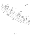
Figure 1 is a perspective view of the track of the invention; -
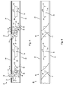
Figure 2 is a front view of the track of the invention; -
Figure 3 is a rear view of the track of the invention; -
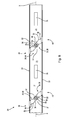
Figure 4 is a top view of the track of the invention; -
Figure 5 is a bottom view of the track of the invention; -
Figure 6 is a perspective view of the reinforcement of the invention shown inFigure 5 with the frame cut away; -
Figure 7A is a left side view of the track of the invention; -
Figure 7B is a right side view of the track of the invention; -
Figure 8 is an alternate embodiment of the track of the invention; -
Figure 9 is a perspective view of the seat adapter of the invention; -
Figure 10 is a front view of the seat adapter of the invention; -
Figure 11 is a rear view of the seat adapter of the invention; -
Figure 12 is a top view of the seat adapter of the invention; -
Figure 13 is a bottom view of the seat adapter of the invention; -
Figure 14 is a left side view of the seat adapter of the invention; -
Figure 15 is a right side view of the seat adapter of the invention; -
Figure 16 is a view of a user wheeling the seat adapter of the invention along the track of the invention; -
Figure 17 is a view of a user positioning the seat adapter of the invention within the track of the invention; -
Figure 18A is a view of a user locking the seat adapter of the invention within the track of the invention; -
Figure 18B is a cross section view of the locking system of the seat adapter engaged within the track of the invention showing the seat adapter in the unlocked position; -
Figure 19A is a view of the locking system of the seat adapter locked by a user and engaged within the track of the invention; -
Figure 19B is a cross section view of the locking system of the seat adapter engaged within the track of the invention showing the seat adapter in the locked position; -
Figure 20A is a detailed view of part of the locking system of the seat adapter showing the lever sliding downwardly and interacting with the safety lock of the seat adapter; -
Figure 20B is a detailed view of part of the locking system of the seat adapter showing the lever and safety lock in the locked position; -
Figure 21 is a view of a seat adapter of the invention in storage mode and a seat adapter of the invention in use; and, -
Figure 22 is a view of a wheelchair secured to the track of the invention. - At the outset, it should be appreciated that like drawing numbers on different drawing views identify identical, or functionally similar, structural elements of the invention. While the present invention is described with respect to what is presently considered to be the preferred aspects, it is to be understood that the invention as claimed is not limited to the disclosed aspect. The present invention is intended to include various modifications and equivalent arrangements within the spirit and scope of the appended claims.
- Furthermore, it is understood that this invention is not limited to the particular methodology, materials and modifications described and as such may, of course, vary. It is also understood that the terminology used herein is for the purpose of describing particular aspects only, and is not intended to limit the scope of the present invention, which is limited only by the appended claims.
- Unless defined otherwise, all technical and scientific terms used herein have the same meaning as commonly understood to one of ordinary skill in the art to which this invention belongs. Although any methods, devices or materials similar or equivalent to those described herein can be used in the practice or testing of the invention, the preferred methods, devices, and materials are now described.
- Adverting now to the Figures,
Figure 1 is a perspective view oftrack 10 of the invention.Track 10 comprises at least onerail having frame 20 which comprisestop surface 21 andsides Top surface 21 connectssides Sides sides top surface 21. It should be appreciated that the top ends ofsides Top surface 21 is perpendicular tosides Frame 20 further comprises axis X which represents a longitudinal axis running along the center offrame 20.Top surface 21 offrame 20 comprisesapertures 25 arranged longitudinally along axis X.Apertures 25 are arranged approximately in the center oftop surface 21.Apertures 25 are parallel withsides apertures 25 are spaced apart by a distance Z between center points A. Preferably, distance Z is approximately 5 inches according to industry standards. -
Apertures 25 are identical. It should be appreciated thatapertures 25 are identical to standard apertures in a horizontal or vertical A-track. Eachaperture 25 comprises pair oftransverse sides longitudinal sides transverse sides Transverse sides longitudinal sides apertures 25 have a quadrilateral shape; specifically, an open rectangular prism shape without top or bottom sides. -
Frame 20 further compriseschannels 30 which connectsides top surface 21.Channels 30 compriselips Channels 30 are identical. It should be appreciated thatchannels 30 represent modified portions of a standard L-track. In the preferred embodiment shown,channels 30 further comprise end portions E1, E2 which are identical to the ends ofapertures 25 wherelongitudinal sides transverse sides lips -
Lips straight portions 35 and plurality of arcuate portions 36 (described in further detail below).Lips top surface 21 betweensides straight portions 35 alternates with each arcuate portion of plurality ofarcuate portions 36 alonglips frame 20 is hollow under top surface 21.Track 10 comprises at least onerail having frame 20 arranged opposite and parallel to a secondrail having frame 20A (described further below).Frames -
Figure 2 shows a front view offrame 20.Top surface 21 is planar andapertures 25 are planar.Apertures 25 are not visible behind the rounded top end ofside 22.Channels 30 are visible through the rounded top end ofside 22.Supportive surfaces 33 are shoulder-like portions withinside 22.Supportive surfaces 33 are parallel withtop surface 21. Plurality ofstraight portions 35 and plurality ofarcuate portions 36 are visible alonglips 32 which connectside 22 toside 23 protruding behindside 22. L-track fittings are arranged to slidingly engagechannels 30.Supportive surfaces 33 provide support for such fittings.Figure 3 shows a rear view offrame 20 which is substantially similar to frame 20 shown inFigure 2 .Frame 20 shown inFigure 3 differs in thatchannels 30 intersect withside 23 rather thanside 22. Moreover, support surfaces 34 are shown distributed alongside 23. Support surfaces 34, like support surfaces 33, are shoulder-like portions withinside 23 and are parallel withtop surface 21.Lips 31 are visible protruding behindside 23 connectingside 23 toside 22 alongtop surface 21. Plurality of straight andarcuate portions lips 31. It should be appreciated thatFigures 2 and 3 are not identical becausechannels 30 are diagonally arranged betweensides -
Figure 4 is a top view offrame 20. Support surfaces 33, 34 ofchannels 30 are positioned below the rounded top ends ofsides arcuate portions lips channels 30 are shown alternating. From the top, right-most portion ofchannels 30,lip 32 proceeds, starting fromside 23, witharcuate portion 35,straight portion 36,arcuate portion 35, end E2,straight portion 36,arcuate portion 35, andstraight portion 36.Straight portions 36 have varying lengths due to the diagonal nature oflip 32. End E2 includes three straight sides of an open rectangular prism. The longitudinal side of end E2proximate side 23 is longer than the longitudinal side of end E2proximate side 22 due to the diagonal nature ofchannels 30. The transverse side of the partial rectangular prism shape of end E2 connects the longitudinal sides of end E2.Lip 31 isopposite lip 32 withinchannels 30. For clarity,lip 32 is annotated inchannel 30 positioned between twoapertures 25.Lip 31 is annotated inchannel 30 positioned on the left. It should be appreciated thatlips channels 30 illustrated inFigure 4 . From the top, left-most portion ofchannels 30,lip 31 proceeds, starting fromside 23, withstraight portion 36,arcuate portion 35,straight portion 36, end E1,arcuate portion 35,straight portion 36, andarcuate portion 35. Again,straight portions 36 have varying lengths due to the diagonal nature oflip 31. End E1 includes three straight sides of an open rectangular prism. The longitudinal side of end E1proximate side 23 is shorter than the longitudinal side of end E1proximate side 22 due to the diagonal nature ofchannels 30. Both ends E1, E2 are open on the top and bottom ends to receive fittings. - Similarly,
apertures 25 are nearly rectangular prisms exceptapertures 25 have open top and bottom faces to receive fittings.Figure 5 is a bottom view offrame 20 showingreinforcements 40.Reinforcements 40 are welded and connectsides sides Reinforcements 40 are correspondingly shaped to reinforcechannels 30. At the center ofreinforcements 40,bolts 41 are arranged to be secured to a floor surface. It should be appreciated that any suitable secure means could be used to securereinforcements 40 to a floor surface for example, screws, nails, pins, soldering, brazing, welding, or cementing. Additionally, eachreinforcement 40 can have more than asingle bolt 41 if desired. -
Figure 6 is a perspective view offrame 20 andreinforcement 40 of the invention.Reinforcement 40 comprisesbase 40A andflanges 40B. As shown inFigure 5 ,base 40A is correspondingly shaped withchannels 30 and is arranged oppositetop surface 21 offrame 20.Flanges 40B areextensions connecting base 40A totop surface 21 andsides frame 20.Flanges 40B are welded tosides top surface 21. In the preferred embodiment,flanges 40B are arranged on the corners ofbase 40Aproximate sides flanges 40B could be arranged in any suitable manner to supportchannels 30. For example,flanges 40B could be a continuous side wall protruding upward frombase 40A betweensides flanges 40B are not continuous betweensides openings 40C are arranged betweenflanges 40Bproximate bolts 41 so that a user can accessbolts 41.Openings 40C additionally decrease the overall mass offrame 20 makingframe 20 lightweight and easy to maneuver. -
Figure 7A is a left side view, or a left end view, offrame 20 andreinforcement 40.Flange 40B arrangedproximate side 22 is welded alongside 22 andtop surface 21. Onlyexterior surface 41 offlange 40B is visible becausereinforcement 40 is arranged diagonally betweensides Side surface 42 is not visible.Base 40A is behindflange 40Bproximate side 22. In contrast,exterior surface 41 andside surface 42 are visible offlange 40Bproximate side 23.Side surface 42 is visibleproximate side 23 becausereinforcement 40 is welded toside 23 at an angle corresponding to the angle ofchannels 30.Side surface 42 connects to base 40A proximate the bottom offlange 40B seamlessly.Figure 7B is a right side view, or a right end view, offrame 20 andreinforcement 40.Figure 7B is identical toFigure 7A .Flange 40Bproximate side 23 is welded alongside 23 andtop surface 21. Only exterior surface offlange 40B is visible.Side surface 42 is not visible. In contrast,exterior surface 41 andside surface 42 are visible with respect toflange 40B weldedproximate side 22. -
Figure 8 is a top view of an alternate embodiment offrame 20 showingchannels 30 without ends E1, E2.Channels 30, in this embodiment, compriselips lips straight portions Lips 32 comprise, from the portionproximate side 23,arcuate portion 35,straight portion 36,arcuate portion 35,straight portion 36,arcuate portion 35, andstraight portion 36.Lips 31 comprise, from the portionproximate side 23,straight portion 36,arcuate portion 35,straight portion 36,arcuate portion 35,straight portion 36, andarcuate portion 35.Bolts 41 are arranged inreinforcements 40 approximately in the center offrame 20 belowlips channels 30. In a further embodiment,frame 20 could comprise any arrangement ofapertures 25 andchannels 30. Instead of alternatingapertures 25 andchannels 30,frame 20 could include a plurality ofapertures 25 arranged adjacent one another followed by a plurality ofchannels 30 arranged adjacent one another. Alternatively,frame 20 could include twoapertures 25 arranged adjacent one another followed by twochannels 30 arranged adjacent one another. Additionally, it should be appreciated thatapertures 25 could be arranged transversely to longitudinal axis X to mimic standard horizontal A-track.Apertures 25 could be modified to emulate standard horizontal and vertical E-tracks.Apertures 25 can even be substituted with circular apertures of the typical F-track.Frame 20 of the instant invention can be arranged in any suitable manner to accommodate any number of track fittings and should not be construed to be limited to A and L tracks.Frame 20 could include ahorizontal aperture 25, avertical aperture 25, a circular aperture of the typical F-track, andchannels 30 of the preferred and alternate embodiments in any pattern, i.e., sequential or alternating. - It should be appreciated that
channels 30 are substantially similar to the standard L-track.Channels 30 alone without ends E1, E2 comprise three equidistant circular apertures separated bystraight portions 36 oflips Straight portions 36 oflips -
Channels 30 are arranged to receive wheelchair tie downs and other L-track fittings.Track 10 can include a plurality offrames 20 mounted within the floor of a vehicle to accommodate any number of seating arrangements. Consistent with the Americans with Disabilities Act, in order to accommodate a wheelchair, a minimum amount of floor space is required (30 inches by 48 inches). Accordingly, track 10 can be arranged with a floor space of a transportation means at least 30 inches by 48 inches.Apertures 25 are arranged to receive A-track fittings. Each aperture is approximately 6.2 centimeters long (or 2.4 inches) by 1.3 centimeters wide (or approximately 0.5 inches). -
Figure 9 shows a perspective view ofseat adapter 100. Broadly,seat adapter 100 compriseshousing 100A andlocking system 100B.Housing 100A comprises bottom 101,left side 102,right side 103, top ofleft side 104, top ofright side 105, front ofleft side 106, rear ofleft side 107, front ofright side 108, and rear ofright side 109. Left andright sides Bottom 101 connects left andright sides right sides right sides right sides left side 106 does not connect to front ofright side 108 and rear ofleft side 107 does not connect to rear ofright side 109. Left andright sides bottom 101 and lockingsystem 100B. It should be appreciated thathousing 100A is preferably made of aluminum or titanium based metals. However,housing 100A could be constructed of any suitable alternative such as iron, steel, or even a sturdy plastic. -
Housing 100A further comprisesextension members left side 107 and rear ofright side 109, respectively,proximate bottom 101. Wheels W are fixedly secured to L-shapedextension members extension members extension member 130A and another wheel W is fixedly secured to L-shapedextension member 131A. Wheels W are identical. Wheels W enable a user to transportseat adapter 100 and a seat fixedly secured thereto. Wheels W also enable a user to guideseat adapter 100 alongside the inward facing walls ofparallel frames track system 50.Hooks bottom 101 proximate wheels W, respectively. Wheels W can be any suitable wheel and/or caster. For example, wheels W could be pneumatic, phenolic, made of rubber, made of polyurethane and threaded, pressed steel, or nylon. Wheels W can be custom made at J.W. Winco located at 2815 South Calhoun Road, New Berlin, WI 53151. Alternatively, a typical wheel and fixed caster can be used. -
Housing 100A also comprisesslots left side 107 and rear ofright side 109, respectively.Locks left side 107 and rear ofright side 109, respectively,proximate slots Slots levers system 100B.Levers slots 118, 119 (described in further detail below). - Locking
system 100B comprisescams levers rung 116.Cams bottom 101opposite hooks wheels W. Cams levers housing 100A.Rung 116 connects levers 114,115 proximate rear of left andright sides -
Figures 9 through 15 show seat adapter 100 in the locked position.Levers bottom 101 and tops of right and leftsides Locks levers cams bottom 101 and forward of fronts of left andright sides opposite hook cams bottom 101. As described below, whenseat adapter 100 and lockingsystem 100B are in the unlocked position, levers 114,115 are arranged at angle P in relation to bottom 101 (as shown inFigure 18B ). Whencams cams bottom 101 and do not protrude beyond the front side ofbottom 101. -
Seat adapter 100 is shown from the front inFigure 10 . Fronts of left andright sides bottom 101 and rung 116 of lockingsystem 100B. In the locked position shown,rung 116 is opposite tops of left andright sides rung 116 is substantially parallel andproximate bottom 101. Wheels W are visible behindrung 116 suspended above the floor surface.Figure 11 shows the rear ofseat adapter 100. Rears of left andright sides bottom 101 and rung 116 of lockingsystem 100B.Slots rear sides levers Locks rear sides proximate slots lock bolts Locks bolts seat adapter 100 is in the locked position, gravity dictates the vertical alignment oflocks levers locks -
Locks angled sides respective shoulders respective appendages Angled sides shoulders right sides Appendages angled sides shoulders locks Angled sides above lock bolts levers push locks bolts levers slots Locks angled side right sides right sides -
Figure 12 shows tops of left andright sides housing 100A ofseat adapter 100. From this view,cams bottom 101.Levers slots slots Locks levers Hooks bottom 101opposite cams Figure 13 showsbottom 101 ofhousing 100A ofseat adapter 100.Hook 110 is shown protruding frombottom 101 proximateleft side 102 andopposite cam 112.Hook 111 is shown protruding frombottom 101 proximateright side 103 andopposite cam 113.Cam 112 is in the locked position and protruding outwardly from bottom 101 proximateleft side 102.Cam 113 is in the locked position protruding outwardly from bottom 101 proximateright side 103.Bottom 101 has a semi-circular aperture connecting front left andright sides bottom 101 has a semi-circular aperture connecting rear left andright sides seat adapter 100 and move the seat andseat adapter 100 without havingbottom 101 ofseat adapter 100 interfere with the gait of the user. -
Left side 102 ofseat adapter 100 is shown inFigure 14 .Lever end 114A is protruding outwardly fromslot 118 and lever end 114A is substantially parallel to the floor surface. Wheel W is suspended above the floor surface.Hook 110 is protruding outwardly from bottom 101 andcam 112 is protruding outwardly from bottom 101 in the opposite direction. Whenseat adapter 100 is lockingly engaged withframe 20 oftrack 10,hook 110 engages undertop surface 21 throughaperture 25 andcam 112 engages undertop surface 21 through anadjacent aperture 25. - Similarly,
right side 103 ofseat adapter 100 is shown inFigure 15 .Lever end 115A is protruding outwardly fromslot 119 and lever end 115A is substantially parallel to the floor surface. Wheel W is suspended above the floor surface.Hook 111 is protruding outwardly from bottom 101 andcam 113 is protruding outwardly from bottom 101 in the opposite direction. Whenseat adapter 100 is lockingly engaged withtrack 10,hook 110 engages undertop surface 21 throughaperture 25 andhook 111 engages undertop surface 21 throughaperture 25 of a parallel frame. Likewise,cam 112 engages undertop surface 21 throughaperture 25 andcam 113 engages undertop surface 21 throughaperture 25 of a parallel frame. - Once
track system 50 is installed, a user can secure a number of desired transit seats each fixed atopseat adapter 100 inside the cabin of a vehicle. For example, a flip style transit seat made by Freedman Seating Company located at 4545 West Augusta Boulevard, Chicago, IL 60651 can be mounted with bolts to top ofleft side 104 and top ofright side 105 ofseat adapter 100. Other flip style transit seats and fixed seats are also compatible withseat adapter 100.Track system 50 comprisesframe 20 spaced apart from and parallel withframe 20A.Track system 50 can include additional frames depending on the desired seating arrangement. - To secure desired
transit seat 250 fixed atopseat adapter 100,user 200, as shown inFigure 16 , tiltsseat 250 andseat adapter 100 onto wheels W and rollsseat 250 andseat adapter 100 forward together.User 200 arranges wheels W between frames 20, 20A such that one wheel W is guided byframe 20 and another wheel W is guided byframe 20A. Whenseat 250 andseat adapter 100 are positioned for storage (to be described below) or for use, a user alignshooks apertures 25 arranged inframes - Then, as shown in
Figure 17 ,user 200tilts seat 250 andseat adapter 100 forward such that hooks 110, 111 protrude into opposingapertures 25 and respectively hook undertop surfaces 21 offrames apertures 25. Asseat 250 andseat adapter 100 are tilted forward further and hooks 110, 111 are hooked in place,bottom 101 ofseat adapter 100 comes into contact withtop surfaces 21 offrames seat adapter 100 comes into full contact withframes cams apertures 25 inframes Hooks parallel apertures 25 offrames cams parallel apertures 25 offrames -
Figure 18A shows howuser 200 securesseat 250 andseat adapter 100 intrack system 50. Onceseat 250 andseat adapter 100 are positioned inapertures 25,user 200, using a single foot, steps downward on top ofrung 116. Asrung 116 is pressed downward, levers 114, 115 slide downward. As discussed above, lever ends 114A, 115A oflevers slots rung 116 is pressed downward, lever ends 114A, 115A slide downwardly throughslots locks angled sides locks bolts locks slots lock bolts slots locks shoulders Figure 19A .Figure 18A illustrates only the portion ofhousing 100A that interacts withframe 20A but it should be appreciated that the other portion ofhousing 100A that interacts withframe 20 functions the same. - The unlocked position of locking
system 100B is shown in cross-section inFigure 18B taken generally alongline 18B-18B shown inFigure 17 .Seat adapter 100 is positioned such thatbottom 101 is resting atopframe 20A.Hook 111 is positioned inaperture 25 such that it is hooked undertop surface 21 offrame 20A.Cam 113 is arranged within a separateadjacent aperture 25 offrame 20A.Lever 115 is arranged lifted upward at angle β. Since lockingsystem 100B is in the unlocked position,cam 113 is not hooked undertop surface 21 offrame 20A.Lever 115 andcam 113 rotate aboutpivot 140.Lock 121 is in its default position partially coveringslot 119.Appendage 133 oflock 121 is shown projecting outwardly such that it should be appreciated thatuser 200 could swing lock 121 out of the way using a single foot.Figure 19A showsrung 116 fully pressed downward andlocking system 100B is in locked position.Lever end 115A is resting atop the bottom ofslot 119.Lock 121 has swung back and lock 121 is again partially coveringslot 119.Shoulder 127 oflock 121 is resting atop lever end 115A.Rung 116 is againproximate bottom 101. Wheels W are still suspended off the floor surface. As shown inFigure 19B , in the locked position,cam 113 pivots forward aboutpivot 140 to hook undertop surface 21 offrame 20A. In this arrangement,lever 115 is proximate to and parallel withbottom 101.Figure 19B is a cross section of lockingsystem 100B taken generally alongline 19B-19B shown inFigure 11 . -
Figure 20A shows a detail view of the interaction betweenlever 115 and lock 121 whenrung 116 is pressed downward. As discussed above, whenrung 116 is pressed downward,lever 115 secured torung 116 is also pressed downward.Lever 115 is guided downward throughslot 119. When lever end 115A contacts angledside 123 oflock 121, lock 121 swings aroundlock bolt 125 in the leftward direction shown. Aslock 121 swings leftwardly,lever 115 is allowed to continue downward throughslot 119.Figure 20B shows a detail oflever 115 and lock 121 afterrung 116 has been fully pressed downward.Shoulder 127 oflock 121 is resting atop lever end 115A. - To disengage
seat adapter 100 fromtrack system 50,user 200 first rotates locks 120, 121 aroundlock bolts locks lock bolts user 200 movesappendages lock bolts appendages bolts locks locks user 200 places a single foot underrung 116 and lifts rung 116 upward.Levers slots lock bolts shoulders locks rung 116 is lifted upward and levers 114, 115pass lock bolts locks rung 116 is lifted upward,cams top surfaces 21 offrames bottom 101 ofhousing 100A. - When
rung 116 is fully lifted andcams housing 100A,user 200 removes his/her foot andrung 116 andlevers Rung 116 andlevers pivot 140. The friction adds to the resistance load present in the levering system such that the total resistance load has a torque sufficient to overcome the torque created by the levering system alone and gravity. This friction pluscams opposite levers pivot 140 enableuser 200 to raise andlower rung 116 in a controlled manner. Withrung 116 raised andcams user 200 simply tiltsseat 250 andseat adapter 100 backward ontowheels W. Cams apertures 25 and hooks 110, 111 are extricated fromadjacent apertures 25. Withhooks track system 50,user 200 is free to rollseat adapter 100 to another position alongtrack system 50 or removeseat 250 andseat adapter 100 altogether. - As shown in
Figure 21 ,seat adapter 100 can be arranged in a storage mode such that a number ofseats 250 andseat adapters 100 can be arranged closely together alongtrack system 50. When a number ofseat adapters 100 are arranged in this manner, seats 250 are not operational because there is insufficient space to flip down the seat portion ofseat 250. However, it is beneficial to be able to storeseats 250 andseat adapters 100 so that whenseats 250 are needed at a later time,seats 250 are easily accessible and easily positionable as described herein.Figure 21 also showsseat adapter 100 arranged for use. As long as nothing causing an obstruction in front ofseat adapter 100, such as another seat adapter,seat adapter 100 is operational provided it is safely secured intrack system 50. - Wheelchairs can be secured to track
system 50 using typical industry tie-downs as follows. At least six frames as described herein are arranged in parallel along a floor. Two front belts are secured to tracks oftrack system 50 which are situated wider than the front of the wheelchair. These belts stabilize the wheelchair side-to-side. Additionally, two rear belts are secured to tracks oftrack system 50; the rear belts should align with the frame of the wheelchair. A lap and shoulder belt is then typically connected to the rear tie downs, the wall, and the user. - Thus, it is seen that the objects of the present invention are efficiently obtained, although modifications and changes to the invention should be readily apparent to those having ordinary skill in the art, which modifications are intended to be within the spirit and scope of the invention as claimed. It also is understood that the foregoing description is illustrative of the present invention and should not be considered as limiting. Therefore, other embodiments of the present invention are possible without departing from the spirit and scope of the present invention.
-
- 10
- track
- 20
- frame
- 20A
- frame
- 21
- top
- 22
- side
- 23
- side
- X
- longitudinal axis
- 25
- aperture
- Z
- distance
- A
- center point
- 26
- pair of transverse sides
- 27
- pair of longitudinal sides
- 28
- pair of transverse sides
- 29
- pair of longitudinal sides
- 30
- channel
- 31
- lip
- 32
- lip
- 33
- support surface
- 34
- support surface
- 35
- plurality of straight portions
- 36
- plurality of arcuate portions
- α
- angle
- 40
- reinforcement
- 40A
- base
- 40B
- flange
- 40C
- opening
- 41
- exterior surface
- 42
- side surface
- 50
- X-track system
- 100
- seat adapter
- 100A
- housing
- 100B
- locking system
- 101
- bottom
- 102
- left side
- 103
- right side
- 104
- top of left side
- 105
- top of right side
- 106
- front of left side
- 107
- rear of left side
- 108
- front of right side
- 109
- rear of right side
- W
- wheel
- W
- wheel
- 110
- hook
- 111
- hook
- 112
- cam
- 112A
- aperture
- 113
- cam
- 113A
- aperture
- 114
- lever
- 114A
- lever end
- 115
- lever
- 115A
- lever end
- 116
- rung
- 118
- slot
- 119
- slot
- 120
- lock
- 121
- lock
- 122
- angled side
- 123
- angled side
- 124
- lock bolt
- 125
- lock bolt
- 126
- shoulder
- 127
- shoulder
- 130
- extension member
- 130A
- L-shaped member
- 131
- extension member
- 131A
- L-shaped member
- 132
- appendage
- 133
- appendage
- 140
- pivot
- 200
- user
- 250
- seat
Claims (14)
- A track (10) assembly for positioning and removably securing wheelchairs and transit seats in a vehicle, comprising:a first rail having a frame (20), said frame (20) comprising a top surface (21), a first side surface (22), a second side surface (23), and a longitudinal axis (X);a plurality of apertures (25) having a shape, said apertures (25) evenly distributed within said top surface (21) along said longitudinal axis (X) of said frame (20);a plurality of channels (30) connecting said first and second side surfaces (22. 23) proximate said top surface (21), said channels (30) evenly distributed along said longitudinal axis (X) of said frame (21); and,a second rail (20A) identical to and arranged in parallel with said first rail (20) to form said track (10) assembly.
- The track assembly for positioning and removably securing wheelchairs and transit seats in a vehicle recited in Claim 1 wherein said first shape is an elongated quadrilateral.
- The track assembly for positioning and removably securing wheelchairs and transit seats in a vehicle recited in Claim 1 wherein said first shape is a rectangle.
- The track assembly for positioning and removably securing wheelchairs and transit seats in a vehicle recited in the preceding Claims, wherein said channels (30) further comprise a first lip (31) having alternating straight and arcuate portions (35, 36) and a second lip (32) opposite from said first lip (31) wherein said second lip (32) comprises respective alternating straight and arcuate portions (35, 36) which are aligned with the alternating straight and arcuate portions (35, 36) of said first lip (31).
- The track assembly for positioning and removably securing wheelchairs and transit seats in a vehicle recited in the preceding Claims wherein said channels (30) are arranged at an angle in relation to said apertures (25).
- The track assembly for positioning and removably securing wheelchairs and transit seats in a vehicle recited in Claim 5 wherein said angle is approximately 45 degrees.
- The track assembly for positioning and removably securing wheelchairs and transit seats in a vehicle recited in the preceding Claims wherein said plurality of apertures (25) and said plurality of channels (30) are alternately arranged.
- The track assembly for positioning and removably securing wheelchairs and transit seats in a vehicle recited in the preceding Claims wherein at least one aperture (25) of said plurality of apertures (25) overlaps at least one channel (30) of said plurality of channels (30).
- The track assembly for positioning and removably securing wheelchairs and transit seats in a vehicle recited in the preceding Claims wherein said frame (20) further comprises a reinforcement means (40).
- A seat adapter (100) for a floor-mounted track for a transportation vehicle for positioning and removably securing transit seats (250), comprising:a housing (100A) having a locking means (100B) pivotally secured to said housing (100A), said locking means (100B) comprising:at least one cam (112, 113);at least one lever (114, 115) fixedly secured to said housing (100A) and said at least one cam (112, 113);a rung (116) fixedly secured to said at least one lever (114, 115);wherein to lockingly engage said seat adapter to said track (10), said at least one cam (112, 113) is aligned with an aperture (25) of said track (10) and said rung (116) is depressed, which, in turn, depresses said at least one lever (114, 115), and, said at least one cam (112, 113) hooks under said aperture (25) of said track (10).
- The seat adapter for a floor-mounted track for a transportation vehicle for positioning and removably securing transit seats (250) recited in Claim 10, further comprising a first extension member (130) opposite a second (131) extension member secured to a first and second rear side (107, 109) of said housing (100A), respectively, proximate said bottom (101) of said housing (100A).
- The seat adapter for a floor-mounted track for a transportation vehicle for positioning and removably securing transit seats (250) recited in the Claims 11 to 12, further comprising a first wheel (W) secured to said first extension member (130) and a second wheel (W) secured to said second extension member (131).
- The seat adapter for a floor-mounted track for a transportation vehicle for positioning and removably securing transit seats recited in the Claims 10 to 12 further comprising a first lock (120) and a second lock (121) arranged to maintain said levers (114, 115) in a locked position.
- Use of a track assembly according to the claims 1 to 9 and use of a seat adapter according to the claims 10 to 13 for positioning and locking wheelchairs and transit seats (250).
Priority Applications (1)
| Application Number | Priority Date | Filing Date | Title |
|---|---|---|---|
| EP15200649.0A EP3025688B1 (en) | 2013-06-17 | 2014-06-16 | Seat adapter for positioning and locking wheelchairs and transit seats |
Applications Claiming Priority (1)
| Application Number | Priority Date | Filing Date | Title |
|---|---|---|---|
| US13/919,684 US20140367545A1 (en) | 2013-06-17 | 2013-06-17 | Track and seat adapter for positioning and locking wheelchairs and transit seats |
Related Child Applications (2)
| Application Number | Title | Priority Date | Filing Date |
|---|---|---|---|
| EP15200649.0A Division-Into EP3025688B1 (en) | 2013-06-17 | 2014-06-16 | Seat adapter for positioning and locking wheelchairs and transit seats |
| EP15200649.0A Division EP3025688B1 (en) | 2013-06-17 | 2014-06-16 | Seat adapter for positioning and locking wheelchairs and transit seats |
Publications (2)
| Publication Number | Publication Date |
|---|---|
| EP2821045A1 true EP2821045A1 (en) | 2015-01-07 |
| EP2821045B1 EP2821045B1 (en) | 2016-08-17 |
Family
ID=50943163
Family Applications (2)
| Application Number | Title | Priority Date | Filing Date |
|---|---|---|---|
| EP15200649.0A Active EP3025688B1 (en) | 2013-06-17 | 2014-06-16 | Seat adapter for positioning and locking wheelchairs and transit seats |
| EP14172463.3A Active EP2821045B1 (en) | 2013-06-17 | 2014-06-16 | Track and seat adapter for positioning and locking wheelchairs and transit seats |
Family Applications Before (1)
| Application Number | Title | Priority Date | Filing Date |
|---|---|---|---|
| EP15200649.0A Active EP3025688B1 (en) | 2013-06-17 | 2014-06-16 | Seat adapter for positioning and locking wheelchairs and transit seats |
Country Status (3)
| Country | Link |
|---|---|
| US (3) | US20140367545A1 (en) |
| EP (2) | EP3025688B1 (en) |
| CA (1) | CA2854395C (en) |
Cited By (2)
| Publication number | Priority date | Publication date | Assignee | Title |
|---|---|---|---|---|
| IT202100003071A1 (en) * | 2021-02-11 | 2022-08-11 | Iveco France Sas | SEAT ASSEMBLY FOR A PUBLIC TRANSPORT VEHICLE |
| US11511814B2 (en) | 2019-11-19 | 2022-11-29 | Braunability Europe Ab | Mounting system for vehicle accessibility apparatus |
Families Citing this family (5)
| Publication number | Priority date | Publication date | Assignee | Title |
|---|---|---|---|---|
| USD797640S1 (en) * | 2016-05-13 | 2017-09-19 | Gary Lee Boone, Jr. | Boat deck track |
| CN106004600B (en) * | 2016-07-27 | 2018-09-04 | 北京汽车研究总院有限公司 | A kind of automotive seat and automobile |
| US11214374B2 (en) * | 2016-08-01 | 2022-01-04 | Gulfstream Aerospace Corporation | Seat track assemblies for vibration isolation of floor mounted components |
| US10259373B1 (en) * | 2017-07-03 | 2019-04-16 | Lannie Stegall | Modular conversion of automotive vehicle to recreational vehicle |
| CN111976844B (en) * | 2020-08-20 | 2022-07-01 | 东风柳州汽车有限公司 | Vehicle body floor assembly, middle-row seat mounting structure and vehicle |
Citations (9)
| Publication number | Priority date | Publication date | Assignee | Title |
|---|---|---|---|---|
| US4771969A (en) | 1987-07-27 | 1988-09-20 | Sabre Industries, Inc. | Leg set track fitting |
| US5083726A (en) | 1989-05-10 | 1992-01-28 | Sabre Industries, Inc. | Seat track bearing for an airplane |
| US5391030A (en) * | 1992-10-14 | 1995-02-21 | Lee; Ray | Wheelchair restraint affixment straps |
| GB2286522A (en) * | 1994-02-16 | 1995-08-23 | Melfin | Vehicle seat slide with memory lock |
| US6892995B2 (en) | 2000-10-19 | 2005-05-17 | Intier Automotive Inc. | Positive engagement latch |
| WO2007060488A2 (en) * | 2005-11-25 | 2007-05-31 | Thomas Soldatos | Mobile aircraft seat-wheelchair for disabled passengers and people requiring assistance |
| DE102009021777A1 (en) * | 2009-05-06 | 2010-11-18 | GM Global Technology Operations, Inc., Detroit | Transport vehicle with floor and seating, includes floor base plate with openings and fastenings for wheel chairs |
| US7975979B2 (en) | 2007-07-27 | 2011-07-12 | Bishop Gmbh | Airplane seat track |
| US8074954B2 (en) | 2007-01-30 | 2011-12-13 | Airbus Deutschland Gmbh | Rail for positioning and locking of elements, and a corresponding fitting |
Family Cites Families (60)
| Publication number | Priority date | Publication date | Assignee | Title |
|---|---|---|---|---|
| US3698678A (en) * | 1970-06-02 | 1972-10-17 | Hansen Mfg Co A L | Load holding device |
| US3713616A (en) * | 1971-03-05 | 1973-01-30 | T Bowers | Load holding device improvement |
| DE2141149A1 (en) | 1971-08-17 | 1973-02-22 | Daimler Benz Ag | SEAT, ESPECIALLY PASSENGER SEAT IN A MOTOR VEHICLE |
| DE2729770C2 (en) * | 1977-07-01 | 1982-03-18 | C. Rob. Hammerstein Gmbh, 5650 Solingen | Locking device for slide rail guides of a vehicle seat |
| JPS60139613A (en) | 1983-12-27 | 1985-07-24 | Kao Corp | Dispersion of antimicrobial agent and antimicrobial hair treatment composition |
| DE3623007A1 (en) | 1986-07-09 | 1988-01-28 | Keiper Recaro Gmbh Co | Sliding element for pairs of seat rails for vehicle seats |
| US4776533A (en) | 1987-03-20 | 1988-10-11 | The Jepson Burns Corporation | Aircraft seat track fitting assembly |
| JPS6460445A (en) | 1987-08-31 | 1989-03-07 | Ohi Seisakusho Co Ltd | Slide device for power seat |
| JPH0639232B2 (en) * | 1990-02-09 | 1994-05-25 | 株式会社大井製作所 | Seat slide device |
| US5156438A (en) * | 1990-02-09 | 1992-10-20 | Ikeda Bussan Co., Ltd. | Automotive seat assembly with safety mechanism |
| JPH0639231B2 (en) * | 1990-02-09 | 1994-05-25 | 株式会社大井製作所 | Folding seat safety device for vehicle |
| US5302063A (en) * | 1992-02-28 | 1994-04-12 | Holden America Inc. | Vehicle wheel chock |
| GB2292175B (en) | 1993-12-20 | 1997-06-25 | Keiper Recaro Gmbh Co | Locking device for car seats,especially motor vehicle seats |
| DE4400474C1 (en) | 1994-01-11 | 1995-03-09 | Keiper Recaro Gmbh Co | Locking device for vehicle seats, in particular motor vehicle seats |
| US5533848A (en) * | 1995-01-03 | 1996-07-09 | Davis; Oliver M. | Payload tie-down system |
| US5547242A (en) * | 1995-02-10 | 1996-08-20 | Atoma International, Inc. | Latch/unlatch indicator for vehicle seat-to floor latch mechanism |
| US5769360A (en) | 1995-03-27 | 1998-06-23 | Research Foundation Of The State University Of New York | Easy transport seat |
| FR2768378B1 (en) * | 1997-09-12 | 1999-11-12 | Faure Bertrand Equipements Sa | SLIDE FOR A REMOVABLE SEAT OF A MOTOR VEHICLE |
| GB9723166D0 (en) | 1997-11-04 | 1998-01-07 | Unwin C N Ltds | Improvements relating to tensioning apparatus |
| MXPA01003166A (en) * | 1998-10-09 | 2003-05-15 | Magna Seating Sys Inc | Automated fold and tumble vehicle seat assembly. |
| US6361098B1 (en) | 1999-03-17 | 2002-03-26 | Daimlerchrysler Corporation | Seat riser fold and tumble mechanism |
| DE60016950T2 (en) | 1999-10-19 | 2005-12-08 | Magna Seating Systems Inc., Aurora | SLIDING RAILING DEVICE WITH STAGELESS LOCKING MECHANISM |
| JP2003512578A (en) | 1999-10-21 | 2003-04-02 | シー.エヌ.アンウィン リミテッド | Fixing equipment improvements |
| US6260813B1 (en) | 2000-01-10 | 2001-07-17 | November Whiskey, Inc. | Aircraft seat track anchor fitting |
| US6514021B2 (en) * | 2001-02-28 | 2003-02-04 | David A. Delay | T-flange engaging load bearing bed |
| DE10238750A1 (en) | 2001-08-24 | 2003-03-13 | Aisin Seiki | Driven carriage device for a seat |
| FR2829439B1 (en) * | 2001-09-07 | 2004-01-16 | Faurecia Sieges Automobile | VEHICLE SEAT BASE, SEAT COMPRISING SUCH A BASE AND SEAT ASSEMBLY COMPRISING SUCH A SEAT |
| KR100442746B1 (en) * | 2001-11-08 | 2004-08-02 | 주식회사다스 | Locking system of seat rail for vehicle |
| US6799927B2 (en) | 2002-08-09 | 2004-10-05 | Donald G. Wheatley | Tie down anchor system |
| DE10257797B3 (en) * | 2002-12-11 | 2004-07-01 | Daimlerchrysler Ag | Cargo space of a motor vehicle |
| US6851523B1 (en) | 2003-10-06 | 2005-02-08 | Ivan Gaster | Shock absorbing vehicle wheel chock |
| US7370832B2 (en) | 2004-03-29 | 2008-05-13 | The Boeing Company | Payload to support track interface and fitting apparatus and methods |
| DE202004007313U1 (en) * | 2004-05-07 | 2005-06-23 | Brose Fahrzeugteile Gmbh & Co. Kommanditgesellschaft, Coburg | Fastening for motor vehicle seat on floor of vehicle has two locking hooks interacting with retaining bolt on floor and rotationally elastically interconnected by torsionable transverse rod |
| KR100604737B1 (en) * | 2004-07-13 | 2006-07-31 | 대원산업 주식회사 | Detachable seat for an automobile |
| WO2006017633A1 (en) * | 2004-08-05 | 2006-02-16 | Johnson Controls Technology Company | Sliding latch system |
| WO2006078721A2 (en) | 2005-01-21 | 2006-07-27 | Heath Tecna Inc. | Aircraft seat track system, apparatus and method |
| NL1028194C2 (en) | 2005-02-04 | 2006-08-07 | Spacefloor B V | Modular floor system. |
| DE102005033048B3 (en) * | 2005-07-15 | 2007-01-04 | Recaro Aircraft Seating Gmbh & Co. Kg | Seat fastening device |
| JP4939810B2 (en) * | 2006-01-27 | 2012-05-30 | 富士機工株式会社 | Vehicle seat slide device |
| US7413390B1 (en) | 2006-05-23 | 2008-08-19 | Allison Jr Thomas | Cargo anchoring system and associated method |
| US7665939B1 (en) | 2006-08-10 | 2010-02-23 | Sure—Lok, Inc. | Retractor anchor with top release |
| US7717655B2 (en) | 2006-09-26 | 2010-05-18 | Sure-Lok, Inc. | Compact wheelchair restraint system with housing and release |
| US7632052B2 (en) * | 2007-01-17 | 2009-12-15 | Portec Rail Products Inc. | Vehicle tire tie-down system and method |
| US7850137B2 (en) | 2007-02-23 | 2010-12-14 | Lear Corporation | Latch system for an adjustable vehicle seat |
| US7976255B2 (en) * | 2007-03-23 | 2011-07-12 | Standard Car Truck Company | Auto-rack railroad car vehicle wheel chock |
| US8047751B2 (en) * | 2007-07-31 | 2011-11-01 | Midwest Precision Products, Inc. | Wheel chock with restraint |
| US8491238B2 (en) * | 2008-01-30 | 2013-07-23 | Holden America, Inc. | Restraint device for a tire |
| US8562264B2 (en) * | 2008-01-30 | 2013-10-22 | Holden America, Inc. | Restraint device for a tire |
| JP5200609B2 (en) | 2008-03-24 | 2013-06-05 | アイシン精機株式会社 | Power seat slide device |
| EP2445786B8 (en) * | 2009-06-23 | 2014-01-08 | Zodiac Seats US LLC | Seat track fitting |
| DE102009034997B4 (en) * | 2009-07-28 | 2015-09-10 | Airbus Operations Gmbh | Holding system with optional grid function |
| JP5362482B2 (en) * | 2009-08-20 | 2013-12-11 | トヨタ紡織株式会社 | Slide rail device for vehicle |
| FR2958230B1 (en) * | 2010-04-02 | 2012-04-13 | Faurecia Sieges Automobile | SLIDER FOR A VEHICLE SEAT AND SEAT COMPRISING SUCH A SLIDER. |
| US8714375B2 (en) * | 2010-10-20 | 2014-05-06 | Standard Car Truck Company | Auto-rack railroad car vehicle wheel chock hanger |
| FR2971976B1 (en) | 2011-02-28 | 2014-07-18 | Eurocopter France | FIXING DEVICE, SEAT PROVIDED WITH SAID DEVICE AND VEHICLE |
| US8702053B2 (en) * | 2011-05-26 | 2014-04-22 | Ford Global Technologies, Llc | Vehicle seat interface assembly |
| US9579241B2 (en) * | 2012-10-12 | 2017-02-28 | Steelcase Inc. | Support arrangement with activation mechanism |
| US9944217B2 (en) * | 2013-02-11 | 2018-04-17 | Ferno-Washington, Inc. | Equipment mounting system |
| US9604656B2 (en) * | 2014-06-12 | 2017-03-28 | Holland, L.P. | Wheel chock storage apparatuses and methods of using the same |
| US20150360600A1 (en) * | 2014-06-12 | 2015-12-17 | Winston Products Llc | Connector anchor having multiple direction connectivity |
-
2013
- 2013-06-17 US US13/919,684 patent/US20140367545A1/en not_active Abandoned
-
2014
- 2014-06-16 EP EP15200649.0A patent/EP3025688B1/en active Active
- 2014-06-16 CA CA2854395A patent/CA2854395C/en active Active
- 2014-06-16 EP EP14172463.3A patent/EP2821045B1/en active Active
-
2016
- 2016-03-09 US US15/065,315 patent/US9550436B2/en active Active
- 2016-03-09 US US15/065,336 patent/US9610861B2/en active Active
Patent Citations (9)
| Publication number | Priority date | Publication date | Assignee | Title |
|---|---|---|---|---|
| US4771969A (en) | 1987-07-27 | 1988-09-20 | Sabre Industries, Inc. | Leg set track fitting |
| US5083726A (en) | 1989-05-10 | 1992-01-28 | Sabre Industries, Inc. | Seat track bearing for an airplane |
| US5391030A (en) * | 1992-10-14 | 1995-02-21 | Lee; Ray | Wheelchair restraint affixment straps |
| GB2286522A (en) * | 1994-02-16 | 1995-08-23 | Melfin | Vehicle seat slide with memory lock |
| US6892995B2 (en) | 2000-10-19 | 2005-05-17 | Intier Automotive Inc. | Positive engagement latch |
| WO2007060488A2 (en) * | 2005-11-25 | 2007-05-31 | Thomas Soldatos | Mobile aircraft seat-wheelchair for disabled passengers and people requiring assistance |
| US8074954B2 (en) | 2007-01-30 | 2011-12-13 | Airbus Deutschland Gmbh | Rail for positioning and locking of elements, and a corresponding fitting |
| US7975979B2 (en) | 2007-07-27 | 2011-07-12 | Bishop Gmbh | Airplane seat track |
| DE102009021777A1 (en) * | 2009-05-06 | 2010-11-18 | GM Global Technology Operations, Inc., Detroit | Transport vehicle with floor and seating, includes floor base plate with openings and fastenings for wheel chairs |
Cited By (3)
| Publication number | Priority date | Publication date | Assignee | Title |
|---|---|---|---|---|
| US11511814B2 (en) | 2019-11-19 | 2022-11-29 | Braunability Europe Ab | Mounting system for vehicle accessibility apparatus |
| IT202100003071A1 (en) * | 2021-02-11 | 2022-08-11 | Iveco France Sas | SEAT ASSEMBLY FOR A PUBLIC TRANSPORT VEHICLE |
| EP4043276A1 (en) * | 2021-02-11 | 2022-08-17 | Iveco France S.A.S. | Seat assembly for a public transport vehicle |
Also Published As
| Publication number | Publication date |
|---|---|
| EP2821045B1 (en) | 2016-08-17 |
| US9550436B2 (en) | 2017-01-24 |
| EP3025688A1 (en) | 2016-06-01 |
| US20140367545A1 (en) | 2014-12-18 |
| CA2854395A1 (en) | 2014-12-17 |
| US20160185257A1 (en) | 2016-06-30 |
| US20160185256A1 (en) | 2016-06-30 |
| EP3025688B1 (en) | 2018-08-08 |
| CA2854395C (en) | 2021-05-25 |
| US9610861B2 (en) | 2017-04-04 |
Similar Documents
| Publication | Publication Date | Title |
|---|---|---|
| EP2821045B1 (en) | Track and seat adapter for positioning and locking wheelchairs and transit seats | |
| JP4679961B2 (en) | Sliding device for vehicle seat | |
| EP1839938A1 (en) | Seat structure for vehicle | |
| US20080101885A1 (en) | Bed divider apparatus and method for use in a pickup truck bed | |
| US20110116886A1 (en) | Apparatus for securing a container on a platform of a transport vehicle | |
| NL7908220A (en) | CARRYING STRUCTURE FOR A CHAIR. | |
| US6183032B1 (en) | Vehicle seating assembly | |
| US9067517B1 (en) | Cantilevered vehicular seat with force distributing locks | |
| US11884191B2 (en) | Personal transportation vehicle with pivoting seat and cargo bay | |
| US20150041608A1 (en) | Adaptable vehicle seat fitting | |
| US11718239B2 (en) | Vehicle roof rack assembly | |
| RU2533296C2 (en) | Method, system and devices for berth installation in confined space | |
| US9688165B2 (en) | Seat assembly for a vehicle | |
| US20220347025A1 (en) | Integrated Wheelchair Tie-Down Systems for a Wheelchair Van or Similar Vehicle | |
| CN111319520A (en) | Vehicle carriage | |
| US20220250533A1 (en) | Restraint system for carts and other cargo | |
| JP6714313B2 (en) | Vehicle structure | |
| US11731537B2 (en) | Passenger seat assembly with child car seat rail system | |
| CN221642339U (en) | Seat and car | |
| JPH042113Y2 (en) | ||
| NL1039036C2 (en) | Floor plate or floor for multifunctional vehicles. | |
| CN221251210U (en) | Track rapid inspection platform | |
| CN218808506U (en) | Cargo boom transportation tool and transport vehicle | |
| JP2002370613A (en) | On-vehicle load coupling device to body floor of automobile | |
| CN219771658U (en) | Lifting platform lapping plate device |
Legal Events
| Date | Code | Title | Description |
|---|---|---|---|
| PUAI | Public reference made under article 153(3) epc to a published international application that has entered the european phase |
Free format text: ORIGINAL CODE: 0009012 |
|
| 17P | Request for examination filed |
Effective date: 20140616 |
|
| AK | Designated contracting states |
Kind code of ref document: A1 Designated state(s): AL AT BE BG CH CY CZ DE DK EE ES FI FR GB GR HR HU IE IS IT LI LT LU LV MC MK MT NL NO PL PT RO RS SE SI SK SM TR |
|
| AX | Request for extension of the european patent |
Extension state: BA ME |
|
| R17P | Request for examination filed (corrected) |
Effective date: 20150626 |
|
| RBV | Designated contracting states (corrected) |
Designated state(s): AL AT BE BG CH CY CZ DE DK EE ES FI FR GB GR HR HU IE IS IT LI LT LU LV MC MK MT NL NO PL PT RO RS SE SI SK SM TR |
|
| GRAP | Despatch of communication of intention to grant a patent |
Free format text: ORIGINAL CODE: EPIDOSNIGR1 |
|
| INTG | Intention to grant announced |
Effective date: 20160127 |
|
| GRAR | Information related to intention to grant a patent recorded |
Free format text: ORIGINAL CODE: EPIDOSNIGR71 |
|
| GRAS | Grant fee paid |
Free format text: ORIGINAL CODE: EPIDOSNIGR3 |
|
| GRAA | (expected) grant |
Free format text: ORIGINAL CODE: 0009210 |
|
| INTG | Intention to grant announced |
Effective date: 20160614 |
|
| AK | Designated contracting states |
Kind code of ref document: B1 Designated state(s): AL AT BE BG CH CY CZ DE DK EE ES FI FR GB GR HR HU IE IS IT LI LT LU LV MC MK MT NL NO PL PT RO RS SE SI SK SM TR |
|
| REG | Reference to a national code |
Ref country code: GB Ref legal event code: FG4D |
|
| REG | Reference to a national code |
Ref country code: CH Ref legal event code: EP |
|
| REG | Reference to a national code |
Ref country code: IE Ref legal event code: FG4D |
|
| REG | Reference to a national code |
Ref country code: AT Ref legal event code: REF Ref document number: 820344 Country of ref document: AT Kind code of ref document: T Effective date: 20160915 |
|
| REG | Reference to a national code |
Ref country code: DE Ref legal event code: R096 Ref document number: 602014003056 Country of ref document: DE |
|
| REG | Reference to a national code |
Ref country code: NL Ref legal event code: MP Effective date: 20160817 |
|
| REG | Reference to a national code |
Ref country code: LT Ref legal event code: MG4D |
|
| REG | Reference to a national code |
Ref country code: AT Ref legal event code: MK05 Ref document number: 820344 Country of ref document: AT Kind code of ref document: T Effective date: 20160817 |
|
| PG25 | Lapsed in a contracting state [announced via postgrant information from national office to epo] |
Ref country code: NO Free format text: LAPSE BECAUSE OF FAILURE TO SUBMIT A TRANSLATION OF THE DESCRIPTION OR TO PAY THE FEE WITHIN THE PRESCRIBED TIME-LIMIT Effective date: 20161117 Ref country code: IT Free format text: LAPSE BECAUSE OF FAILURE TO SUBMIT A TRANSLATION OF THE DESCRIPTION OR TO PAY THE FEE WITHIN THE PRESCRIBED TIME-LIMIT Effective date: 20160817 Ref country code: RS Free format text: LAPSE BECAUSE OF FAILURE TO SUBMIT A TRANSLATION OF THE DESCRIPTION OR TO PAY THE FEE WITHIN THE PRESCRIBED TIME-LIMIT Effective date: 20160817 Ref country code: FI Free format text: LAPSE BECAUSE OF FAILURE TO SUBMIT A TRANSLATION OF THE DESCRIPTION OR TO PAY THE FEE WITHIN THE PRESCRIBED TIME-LIMIT Effective date: 20160817 Ref country code: LT Free format text: LAPSE BECAUSE OF FAILURE TO SUBMIT A TRANSLATION OF THE DESCRIPTION OR TO PAY THE FEE WITHIN THE PRESCRIBED TIME-LIMIT Effective date: 20160817 Ref country code: NL Free format text: LAPSE BECAUSE OF FAILURE TO SUBMIT A TRANSLATION OF THE DESCRIPTION OR TO PAY THE FEE WITHIN THE PRESCRIBED TIME-LIMIT Effective date: 20160817 Ref country code: HR Free format text: LAPSE BECAUSE OF FAILURE TO SUBMIT A TRANSLATION OF THE DESCRIPTION OR TO PAY THE FEE WITHIN THE PRESCRIBED TIME-LIMIT Effective date: 20160817 |
|
| PG25 | Lapsed in a contracting state [announced via postgrant information from national office to epo] |
Ref country code: LV Free format text: LAPSE BECAUSE OF FAILURE TO SUBMIT A TRANSLATION OF THE DESCRIPTION OR TO PAY THE FEE WITHIN THE PRESCRIBED TIME-LIMIT Effective date: 20160817 Ref country code: GR Free format text: LAPSE BECAUSE OF FAILURE TO SUBMIT A TRANSLATION OF THE DESCRIPTION OR TO PAY THE FEE WITHIN THE PRESCRIBED TIME-LIMIT Effective date: 20161118 Ref country code: SE Free format text: LAPSE BECAUSE OF FAILURE TO SUBMIT A TRANSLATION OF THE DESCRIPTION OR TO PAY THE FEE WITHIN THE PRESCRIBED TIME-LIMIT Effective date: 20160817 Ref country code: PL Free format text: LAPSE BECAUSE OF FAILURE TO SUBMIT A TRANSLATION OF THE DESCRIPTION OR TO PAY THE FEE WITHIN THE PRESCRIBED TIME-LIMIT Effective date: 20160817 Ref country code: AT Free format text: LAPSE BECAUSE OF FAILURE TO SUBMIT A TRANSLATION OF THE DESCRIPTION OR TO PAY THE FEE WITHIN THE PRESCRIBED TIME-LIMIT Effective date: 20160817 Ref country code: ES Free format text: LAPSE BECAUSE OF FAILURE TO SUBMIT A TRANSLATION OF THE DESCRIPTION OR TO PAY THE FEE WITHIN THE PRESCRIBED TIME-LIMIT Effective date: 20160817 Ref country code: PT Free format text: LAPSE BECAUSE OF FAILURE TO SUBMIT A TRANSLATION OF THE DESCRIPTION OR TO PAY THE FEE WITHIN THE PRESCRIBED TIME-LIMIT Effective date: 20161219 |
|
| PG25 | Lapsed in a contracting state [announced via postgrant information from national office to epo] |
Ref country code: RO Free format text: LAPSE BECAUSE OF FAILURE TO SUBMIT A TRANSLATION OF THE DESCRIPTION OR TO PAY THE FEE WITHIN THE PRESCRIBED TIME-LIMIT Effective date: 20160817 Ref country code: EE Free format text: LAPSE BECAUSE OF FAILURE TO SUBMIT A TRANSLATION OF THE DESCRIPTION OR TO PAY THE FEE WITHIN THE PRESCRIBED TIME-LIMIT Effective date: 20160817 |
|
| REG | Reference to a national code |
Ref country code: DE Ref legal event code: R097 Ref document number: 602014003056 Country of ref document: DE |
|
| PG25 | Lapsed in a contracting state [announced via postgrant information from national office to epo] |
Ref country code: CZ Free format text: LAPSE BECAUSE OF FAILURE TO SUBMIT A TRANSLATION OF THE DESCRIPTION OR TO PAY THE FEE WITHIN THE PRESCRIBED TIME-LIMIT Effective date: 20160817 Ref country code: SM Free format text: LAPSE BECAUSE OF FAILURE TO SUBMIT A TRANSLATION OF THE DESCRIPTION OR TO PAY THE FEE WITHIN THE PRESCRIBED TIME-LIMIT Effective date: 20160817 Ref country code: SK Free format text: LAPSE BECAUSE OF FAILURE TO SUBMIT A TRANSLATION OF THE DESCRIPTION OR TO PAY THE FEE WITHIN THE PRESCRIBED TIME-LIMIT Effective date: 20160817 Ref country code: BG Free format text: LAPSE BECAUSE OF FAILURE TO SUBMIT A TRANSLATION OF THE DESCRIPTION OR TO PAY THE FEE WITHIN THE PRESCRIBED TIME-LIMIT Effective date: 20161117 Ref country code: DK Free format text: LAPSE BECAUSE OF FAILURE TO SUBMIT A TRANSLATION OF THE DESCRIPTION OR TO PAY THE FEE WITHIN THE PRESCRIBED TIME-LIMIT Effective date: 20160817 Ref country code: BE Free format text: LAPSE BECAUSE OF FAILURE TO SUBMIT A TRANSLATION OF THE DESCRIPTION OR TO PAY THE FEE WITHIN THE PRESCRIBED TIME-LIMIT Effective date: 20160817 |
|
| PLBE | No opposition filed within time limit |
Free format text: ORIGINAL CODE: 0009261 |
|
| STAA | Information on the status of an ep patent application or granted ep patent |
Free format text: STATUS: NO OPPOSITION FILED WITHIN TIME LIMIT |
|
| 26N | No opposition filed |
Effective date: 20170518 |
|
| PG25 | Lapsed in a contracting state [announced via postgrant information from national office to epo] |
Ref country code: SI Free format text: LAPSE BECAUSE OF FAILURE TO SUBMIT A TRANSLATION OF THE DESCRIPTION OR TO PAY THE FEE WITHIN THE PRESCRIBED TIME-LIMIT Effective date: 20160817 |
|
| PG25 | Lapsed in a contracting state [announced via postgrant information from national office to epo] |
Ref country code: MC Free format text: LAPSE BECAUSE OF FAILURE TO SUBMIT A TRANSLATION OF THE DESCRIPTION OR TO PAY THE FEE WITHIN THE PRESCRIBED TIME-LIMIT Effective date: 20160817 |
|
| REG | Reference to a national code |
Ref country code: CH Ref legal event code: PL |
|
| REG | Reference to a national code |
Ref country code: IE Ref legal event code: MM4A |
|
| REG | Reference to a national code |
Ref country code: FR Ref legal event code: ST Effective date: 20180228 |
|
| PG25 | Lapsed in a contracting state [announced via postgrant information from national office to epo] |
Ref country code: CH Free format text: LAPSE BECAUSE OF NON-PAYMENT OF DUE FEES Effective date: 20170630 Ref country code: IE Free format text: LAPSE BECAUSE OF NON-PAYMENT OF DUE FEES Effective date: 20170616 Ref country code: LU Free format text: LAPSE BECAUSE OF NON-PAYMENT OF DUE FEES Effective date: 20170616 Ref country code: LI Free format text: LAPSE BECAUSE OF NON-PAYMENT OF DUE FEES Effective date: 20170630 |
|
| PG25 | Lapsed in a contracting state [announced via postgrant information from national office to epo] |
Ref country code: FR Free format text: LAPSE BECAUSE OF NON-PAYMENT OF DUE FEES Effective date: 20170630 |
|
| PG25 | Lapsed in a contracting state [announced via postgrant information from national office to epo] |
Ref country code: MT Free format text: LAPSE BECAUSE OF NON-PAYMENT OF DUE FEES Effective date: 20170616 |
|
| PG25 | Lapsed in a contracting state [announced via postgrant information from national office to epo] |
Ref country code: AL Free format text: LAPSE BECAUSE OF FAILURE TO SUBMIT A TRANSLATION OF THE DESCRIPTION OR TO PAY THE FEE WITHIN THE PRESCRIBED TIME-LIMIT Effective date: 20160817 |
|
| PG25 | Lapsed in a contracting state [announced via postgrant information from national office to epo] |
Ref country code: HU Free format text: LAPSE BECAUSE OF FAILURE TO SUBMIT A TRANSLATION OF THE DESCRIPTION OR TO PAY THE FEE WITHIN THE PRESCRIBED TIME-LIMIT; INVALID AB INITIO Effective date: 20140616 |
|
| PG25 | Lapsed in a contracting state [announced via postgrant information from national office to epo] |
Ref country code: CY Free format text: LAPSE BECAUSE OF FAILURE TO SUBMIT A TRANSLATION OF THE DESCRIPTION OR TO PAY THE FEE WITHIN THE PRESCRIBED TIME-LIMIT Effective date: 20160817 |
|
| PG25 | Lapsed in a contracting state [announced via postgrant information from national office to epo] |
Ref country code: MK Free format text: LAPSE BECAUSE OF FAILURE TO SUBMIT A TRANSLATION OF THE DESCRIPTION OR TO PAY THE FEE WITHIN THE PRESCRIBED TIME-LIMIT Effective date: 20160817 |
|
| PG25 | Lapsed in a contracting state [announced via postgrant information from national office to epo] |
Ref country code: TR Free format text: LAPSE BECAUSE OF FAILURE TO SUBMIT A TRANSLATION OF THE DESCRIPTION OR TO PAY THE FEE WITHIN THE PRESCRIBED TIME-LIMIT Effective date: 20160817 |
|
| PG25 | Lapsed in a contracting state [announced via postgrant information from national office to epo] |
Ref country code: IS Free format text: LAPSE BECAUSE OF FAILURE TO SUBMIT A TRANSLATION OF THE DESCRIPTION OR TO PAY THE FEE WITHIN THE PRESCRIBED TIME-LIMIT Effective date: 20161217 |
|
| PGFP | Annual fee paid to national office [announced via postgrant information from national office to epo] |
Ref country code: GB Payment date: 20240627 Year of fee payment: 11 |
|
| PGFP | Annual fee paid to national office [announced via postgrant information from national office to epo] |
Ref country code: DE Payment date: 20240627 Year of fee payment: 11 |