EP2820769B1 - Système et procédé de transmission en liaison montante dans un réseau sans fil - Google Patents
Système et procédé de transmission en liaison montante dans un réseau sans fil Download PDFInfo
- Publication number
- EP2820769B1 EP2820769B1 EP13755729.4A EP13755729A EP2820769B1 EP 2820769 B1 EP2820769 B1 EP 2820769B1 EP 13755729 A EP13755729 A EP 13755729A EP 2820769 B1 EP2820769 B1 EP 2820769B1
- Authority
- EP
- European Patent Office
- Prior art keywords
- packet
- field
- station
- access point
- short
- Prior art date
- Legal status (The legal status is an assumption and is not a legal conclusion. Google has not performed a legal analysis and makes no representation as to the accuracy of the status listed.)
- Active
Links
- 238000000034 method Methods 0.000 title claims description 45
- 230000005540 biological transmission Effects 0.000 title description 53
- 230000011664 signaling Effects 0.000 claims description 31
- 238000012549 training Methods 0.000 claims description 18
- 238000004891 communication Methods 0.000 claims description 4
- 125000004122 cyclic group Chemical group 0.000 claims description 2
- 238000012545 processing Methods 0.000 description 14
- 230000015654 memory Effects 0.000 description 8
- 230000007704 transition Effects 0.000 description 4
- 238000010586 diagram Methods 0.000 description 2
- 238000007726 management method Methods 0.000 description 2
- 230000008569 process Effects 0.000 description 2
- 230000004075 alteration Effects 0.000 description 1
- 230000008859 change Effects 0.000 description 1
- 238000010276 construction Methods 0.000 description 1
- 238000013500 data storage Methods 0.000 description 1
- 230000006870 function Effects 0.000 description 1
- 230000010354 integration Effects 0.000 description 1
- 230000003287 optical effect Effects 0.000 description 1
- 230000002093 peripheral effect Effects 0.000 description 1
- 239000007787 solid Substances 0.000 description 1
- 230000003068 static effect Effects 0.000 description 1
- 238000006467 substitution reaction Methods 0.000 description 1
- 230000001360 synchronised effect Effects 0.000 description 1
Images


Classifications
-
- H—ELECTRICITY
- H04—ELECTRIC COMMUNICATION TECHNIQUE
- H04L—TRANSMISSION OF DIGITAL INFORMATION, e.g. TELEGRAPHIC COMMUNICATION
- H04L1/00—Arrangements for detecting or preventing errors in the information received
- H04L1/004—Arrangements for detecting or preventing errors in the information received by using forward error control
- H04L1/0072—Error control for data other than payload data, e.g. control data
-
- H—ELECTRICITY
- H04—ELECTRIC COMMUNICATION TECHNIQUE
- H04W—WIRELESS COMMUNICATION NETWORKS
- H04W72/00—Local resource management
- H04W72/20—Control channels or signalling for resource management
-
- H—ELECTRICITY
- H04—ELECTRIC COMMUNICATION TECHNIQUE
- H04L—TRANSMISSION OF DIGITAL INFORMATION, e.g. TELEGRAPHIC COMMUNICATION
- H04L1/00—Arrangements for detecting or preventing errors in the information received
- H04L1/12—Arrangements for detecting or preventing errors in the information received by using return channel
- H04L1/16—Arrangements for detecting or preventing errors in the information received by using return channel in which the return channel carries supervisory signals, e.g. repetition request signals
- H04L1/1607—Details of the supervisory signal
-
- H—ELECTRICITY
- H04—ELECTRIC COMMUNICATION TECHNIQUE
- H04L—TRANSMISSION OF DIGITAL INFORMATION, e.g. TELEGRAPHIC COMMUNICATION
- H04L1/00—Arrangements for detecting or preventing errors in the information received
- H04L1/12—Arrangements for detecting or preventing errors in the information received by using return channel
- H04L1/16—Arrangements for detecting or preventing errors in the information received by using return channel in which the return channel carries supervisory signals, e.g. repetition request signals
- H04L1/18—Automatic repetition systems, e.g. Van Duuren systems
-
- H—ELECTRICITY
- H04—ELECTRIC COMMUNICATION TECHNIQUE
- H04W—WIRELESS COMMUNICATION NETWORKS
- H04W74/00—Wireless channel access
- H04W74/08—Non-scheduled access, e.g. ALOHA
- H04W74/0808—Non-scheduled access, e.g. ALOHA using carrier sensing, e.g. carrier sense multiple access [CSMA]
- H04W74/0816—Non-scheduled access, e.g. ALOHA using carrier sensing, e.g. carrier sense multiple access [CSMA] with collision avoidance
Definitions
- the present invention relates to a system and method for wireless communications, and, in particular, to a system and method for uplink transmission in a wireless network.
- IEEE 802.11 ah defines a local area network protocol especially for sub 1 GHz carrier frequencies.
- the main requirements of IEEE 802.11 ah include: a longer coverage area (e.g., up to 1km), a physical (PHY) layer data rate of at least 100 kbps, a maximum aggregate multi-station data rate of 20Mbps, the use of orthogonal frequency division multiplexing (OFDM) PHY modulation, and support a number of associations beyond 2007 for outdoor applications.
- PHY physical
- OFDM orthogonal frequency division multiplexing
- IEEE 802.11 defines a request to send (RTS)/clear to send (CTS) process.
- the station first broadcasts an RTS packet indicating that the station will send the packet to the specified access point for a specified duration. After receiving the RTS packet, the access point also broadcasts a CTS packet to confirm the station's packet transmission. All other stations receiving either RTS or CTS packets will know not to transmit their packets until the end of indicated duration. By following this procedure, collision may be avoided.
- Document D2 shows a legacy MAC CTS format ( figure 6B ) and a shortened CTS MAC format ( figure 7B ), the latter only including the "duration" field. As indicated in paragraph 0040 of D2, the MAC frames are assumed to be preceded by the conventional physical preamble of IEEE 802.11x standards.
- the present invention relates to a method of communicating a short CTS frame and a corresponding network element according to the accompanying claims.
- a method of communicating in a wireless network includes communicating, by a network element, a short clear-to-send (CTS) frame including a first short training field and a first long training field. Also, the short CTS frame includes a first signaling field including a first duration field and a first address of the station.
- CTS clear-to-send
- a method of communicating, by a network element, a first non-data frame indicating that a wireless medium is idle where the first non-data frame includes a first short training field and a first long training field. Also, the first non-data frame includes a first signaling field including a first packet type field and a first field indicating addresses of a plurality of target stations.
- a network element includes a processor and a computer readable storage medium storing programming for execution by the processor.
- the programming includes instructions to communicate a short clear-to-send (CTS) frame including a short training field and a long training field.
- CTS clear-to-send
- the short CTS frame includes a signaling field including a duration field and an address of an access point.
- a network element includes a processor and a computer readable storage medium storing programming for execution by the processor.
- the programming includes instructions to communicate a first non-data frame indicating that a wireless medium is idle, where the first non-data frame includes a first short training field and a first long training field.
- the first non-data frame includes a first signaling field including a first packet type field and a first field indicating addresses of a plurality of target stations.
- Figure 1 illustrates an uplink collision 110 between two stations covered by an access point.
- Station 1 and Station 2 are both within range of a single access point, but they are not in range of each other.
- both stations would transmit uplink data to the access point at the same time, because each station does not know about the presence of the other station.
- FIG. 2 illustrates a request to send (RTS) packet 122 and a clear to send (CTS) packet 124 which may be used to prevent collisions.
- RTS request to send
- CTS clear to send
- Packet transmission based on RTS packets and CTS packets has a relatively large amount of overhead.
- the RTS packet 122 contains two octets for packet control, two octets for duration, six octets for receiver address, six octets for transmitter address, and four octets for a frame check sequence (FCS).
- FCS frame check sequence
- the media access control (MAC) header of the RTS contains the frame control, duration, receiver address, and transmitter address.
- the CTS packet contains two octets for frame control, two octets for duration, six octets for a receiver address, and four octets for FCS, for a total of 14 octets.
- the MAC header of the CTS packet 124 includes the frame control, duration, and receiver address.
- the CTS packet 122 and the RTS packet 124 are usually transmitted with the lowest modulation and coding scheme (MCS) level, because other stations close to the requesting station have to be able to decode these packets. Transmitting the packets using the lowest MCS level makes the payload size large.
- MCS modulation and coding scheme
- Figure 3 illustrates system 100 for uplink transmission in a wireless network that includes first station 104, second station 106, and access point 102.
- First station 104 and second station 106 cannot directly communicate with each other, because they are too far apart. However, both first station 104 and second station 106 can and do communicate with access point 102.
- Both first station 104 and second station 106 transmit a short RTS frame to access point 102.
- Access point 102 then responds, if the media channel is available, with a short CTS frame. Access point 102 will only grant a short CTS frame to one station at a time, so that only one station is transmitting to access point 102 at a time.
- a station In uplink transmission, when a station has data to transmit, the station initially transmits a short RTS frame, which is a non-data packet indicating the station address and the access point address.
- a short RTS frame When an access point receives a short RTS frame, and the access point is free to receive packets, the access point transmits a short CTS frame, which is also a non-data packet that includes the address of the station that sent the short RTS frame.
- An example of packet 130 that may be used as a short RTS frame and a short CTS frame is illustrated in Figure 4 .
- packet 130 may consist of only a physical (PHY) layer preamble.
- Frame 130 includes a short training field (STF), a long training field (LTF), and a signaling field (SIG).
- STF short training field
- LTF long training field
- SIG signaling field
- the short training field and the long training field constitute the physical layer preamble.
- the short training field is used for initial frame synchronization, for coarse frequency offset compensation, and for automatic gain control (AGC) settings.
- the long training field is used for fine frequency offset compensation and channel estimation.
- the signaling field contains 36 information bits.
- the signaling field may include a packet type field, an address of the target access point, an address of the requesting station, a duration field, and/or a cyclic redundancy check (CRC).
- the duration field may be equal to or greater than the expected duration of the current uplink packet transmission.
- the duration of the current uplink packet transmission may include the duration of the station's uplink transmission and additional times. The additional times may include the time for the access point's acknowledgment frame transmission, the time for the access point's short CTS frame, and time gaps between the transmissions.
- the duration field is one or more of the most significant bits (MSB) of the size of the expected duration of the current uplink packet transmission.
- the signaling field of the short RTS frame may also include tail bits for Viterbi decoding.
- the duration field includes an estimated time for the whole uplink transmission process.
- the packet type field may indicate a specific message that this packet delivers, so that the access point can understand the signature field.
- the packet type field indicates that the packet is a short RTS frame.
- the packet type field may contain two parts, where the first part is a one bit indication that this signature field is for normal usage or as a special packet type, and a second part to indicate which special packet type the signature field represents.
- the second part may indicate the signature field is for a short clear-to-send (CTS) frame or a short RTS frame.
- CTS clear-to-send
- the packet type field contains four bits, where one bit indicates if it is a special packet, and the remaining three bits indicate eight different types of special packets.
- the short RTS frame may be encoded in the lowest MCS level.
- the signaling field may, for example, contain one bit that indicates a special signature type. For example, if the special signature type contains a 1, that the signaling field is used for special purposes, for example as a short RTS frame, and if the special signature type contains a 0, the signaling field provides information for decoding the payload that follows this signaling field.
- a length field is defined in the signature field. A non-zero length field indicates a normal packet with a length of the value, while a zero length indicates that the signaling field is used for special purposes, for example as a short RTS frame.
- a signaling field of a short CTS frame includes a packet type field, an address of the target station, and a CRC.
- the packet type field indicates a specific message that this packet delivers, so that the receiver can understand the signature field.
- the packet type field may indicate that the packet is a short CTS frame.
- the address of the target station may include all or part of an association identification (AID).
- the address of the transmitting station in a short CTS frame may match the address of the requesting station in a corresponding short RTS frame.
- the signaling field of the short CTS frame may also include information on the expected duration of the current uplink packet transmission, which is equal to or greater than the expected duration of the current uplink packet transmission.
- the duration of the current uplink packet transmission may include the station's uplink data packet transmission time and other related times, such as the access point's acknowledgment fame transmission time and the time gap between the transmissions.
- the duration field is one or more of the most significant bits of the size of the expected duration of the current uplink packet transmission.
- the duration field is the same as the duration field for a corresponding short RTS frame minus the time difference between short RTS frame transmission and short CTS frame transmission.
- the duration field may include an estimated time that a whole uplink transmission process is completed.
- the signaling field of the short CTS frame may also include tail bits for Viterbi decoding.
- the short CTS frame is encoded in the lowest MCS level.
- the signature field also includes information on the identity of the currently transmitting access point.
- the packet type field may indicate a short CTS frame.
- the signaling field may contain one bit that indicates a special signature type.
- the one bit in the special signature type is a 1
- it may indicate that the signaling field is used for special purposes, for example as a short CTS frame
- if the one bit in the special signature type is a 0, it indicates that the signaling field provides information for decoding the payload that follows this signaling field.
- a length field is defined in the signature field.
- a non-zero length field indicates a normal packet with a length of the value, while a zero length indicates a special signature field.
- the packet type field is set to a unique value that indicates a short CTS frame.
- the packet type field indicates if the access point intends to transmit its own packet with another unique ID.
- the packet type field may be set to yet another unique ID that indicates that every station can transmit uplink packets.
- the short CTS frame is encoded in the lowest MCS level.
- a method of uplink data transmission performed by a station is illustrated in Figure 5 .
- the station transmits a short RTS frame to the access point.
- the station attempts to receive a short CTS frame.
- the short RTS frame is operating as a transmission request packet
- the short CTS frame is operating as a transmission grant packet. If the station receives a valid short CTS frame, the station transmits data in step 136.
- a short CTS frame is valid only if the station address in the short RTS frame matches the station address of the short CTS frame.
- a short CTS frame is valid only if the duration field of the short CTS frame matches the duration field of the short RTS frame.
- a match does not require that the duration fields be identical, because there is a time difference between a short RTS packet transmission and a short CTS packet transmission, and a match accounts for this.
- the duration and the station address of both the short RTS frame and the short CTS frame must match for the short CTS frame to be valid. However, if the station does not receive a short CTS frame, the station transmits another short RTS frame.
- Figure 6 illustrates a method of uplink data reception performed by an access point. Initially, the access point receives a short RTS frame from a station in step 112. Then, in step 114, the access point transmits a short CTS frame to the requesting station. Finally, in step 116, the access point receives data from the station that was granted by the short RTS frame.
- a traditional RTS packet includes six octets for a BSSID to identify the access points. However, six octets may not be necessary to uniquely identify the access point within range.
- An access point address may be generated in accordance with a portion of the BSSID to identify an access point.
- Figure 7 illustrates a method of setting a partial BSSID to identify an access point.
- the access point broadcasts its partial BSSID.
- the partial BSSID might be broadcast periodically in a beacon packet.
- nearby stations monitor the BSSIDs of nearby access points. If a station ascertains that more than one access point is using the same partial BSSID, the station notifies one of the access points in step 188. Then, the access point sets its partial BSSID to a different partial BSSID that does not conflict with the nearby access points in step 182.
- octets are used for a station address for a traditional RTS packet or a traditional CTS packet.
- six octets are often not required to uniquely identify stations.
- a station address is generated in accordance with a portion of an AID to identify the stations within a range.
- a random number is used to identify the stations. If a random number is used for a station address, each time a station transmits a short RTS frame, the station address can be different, which might cause the access point to not be able to correctly identify with station corresponds to the short RTS frame. However, the access point will use the same station address to indicate the target station identity when it broadcasts a short CTS frame.
- the station fails to receive a short CTS frame, if the received target station address is different from its own station address, or, optionally, if the received duration information is different from its own duration field, the station retransmits a short RTS frame using a different randomly generated address.
- An access point might use a short CTS frame for other purposes, such as when the access point wants to transmit its own downlink packet, or to prevent stations from transmitting data packets. Additionally, an access point might use a short CTS frame to indicate that currently the wireless medium is idle and that every associated station can try to uplink data packets to prevent stations from waiting for an uplink packet. For these additional uses, specific bits in the packet type field might be allocated to indicate the usage or one or more of target station addresses are dedicated for these purposes.
- the stations waits to receive a packet from an access point.
- the packet might be an access point broadcast non-data packet indicating that the media is idle, an acknowledgement packet for transmission by another station, an access point management packet including upload scheduling information, a download traffic packet with information on packet duration including upload acknowledgement transmission time from the receiver, and that the current time is no sooner than the estimated end time of the upload acknowledgement transmission, or others.
- the access point's broadcast packet indicating that the media is idle is achieved using a short CTS frame.
- a method of uplink data transmission where a station waits for a short CTS frame that is broadcast to all stations by an access point is illustrated in Figure 8 .
- the method includes messages from the station 144 and messages from the access point 142. Initially, when the station transitions from a sleep state to an active state, and has packets to uplink, the station waits until an access point broadcasts a short CTS frame. The station waits for a distributed coordinated function (DCF) interframe space (DIFS) plus a random backoff duration, and then sends a short RTS frame to the access point. After the access point receives the short RTS frame, the access point waits for a short interframe space (SIFS), and then sends a short CTS frame only to the requesting station. After the station receives the short CTS frame, the station waits for a SIFS, and then begins data packet transmission to the access point. If the transmission is successful, the station may receive an acknowledgement packet from the access point.
- DIFS distributed coordinated function interframe space
- Figure 9 illustrates a method of uplink data transmission where a station waits for a beacon signal from the access point.
- the method includes messages from the station 154 and messages from the access point 152. Initially, when the station transitions from a sleep state to an active state, and has packets to uplink, the station waits until the access point broadcasts a beacon packet. Upon receiving the beacon packet, the station waits for a DIFS plus a random backoff duration, and then sends a short RTS frame to the access point. After the access point receives the short RTS frame, the access point waits for a SIFS, and then sends a short CTS frame only to the requesting station. Then, after the station receives the short CTS frame, the station waits for a SIFS, and then begins data packet transmission to the access point. If the transmission is successful, the station may receive an acknowledgement packet from the access point.
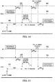
- Figure 10 illustrates a method of uplink data transmission where a station waits for an acknowledgement message from an access point to another station.
- the method includes messages from the requesting station 166, messages from an already transmitting station 164, and messages from the access point 162.
- the requesting station transitions from a sleep state to an active state, and has packets to upload
- the already transmitting station is transmitting data packets to the access point.
- the access point waits for a SIFS, and broadcasts an acknowledgement packet.
- the requesting station receives the acknowledgement packet, it waits for a DIFS plus a random backoff duration, and transmits a short RTS frame to the access point.
- the access point when the access point receives the short RTS frame, it waits for a SIFS, and transmits a short CTS frame to the requesting station. Next, when the requesting station receives the short CTS fame, the requesting station waits for a SIFS, and then transmits data packets to the access point. If the transmission is successful, the access point may broadcast an acknowledgement packet.
- Figure 11 illustrates a method of uplink data transmission where a requesting station waits for an acknowledge message from a transmitting station.
- the method includes messages from an access point 172, messages from an already transmitting station 174, and messages from a requesting station 176.
- the requesting station transitions from a sleep state to an alert state, and it has packets to transmit. Meanwhile, the access point transmits data to the already receiving station.
- the receiving station waits for a SIFS, and broadcasts an acknowledgement message.
- the requesting station waits for a DIFS plus a random backoff duration, and sends a short RTS to the access point.
- the access point Upon receiving the short RTS, the access point waits for a SIFS and sends a short CTS frame to the requesting station. The requesting station waits for a SIFS, and begins transmitting data to the access point. If the transmission is successful, the access point may broadcast an acknowledgement packet.
- a station may, for example, receive a management packet including uplink scheduling information, and the current time is the time that is designated for the station to transmit. Also, the access point may change the allowed user group for uplink transmission for multiple consecutive transmissions of packets, indicating that currently the wireless medium is idle and the stations are allowed to transmit uplink data packets.
- FIG. 12 illustrates a block diagram of processing system 270 that may be used for implementing the devices and methods disclosed herein.
- Specific devices may utilize all of the components shown, or only a subset of the components, and levels of integration may vary from device to device.
- a device may contain multiple instances of a component, such as multiple processing units, processors, memories, transmitters, receivers, etc.
- the processing system may comprise a processing unit equipped with one or more input devices, such as a microphone, mouse, touchscreen, keypad, keyboard, and the like.
- processing system 270 may be equipped with one or more output devices, such as a speaker, a printer, a display, and the like.
- the processing unit may include central processing unit (CPU) 274, memory 276, mass storage device 278, video adapter 280, and I/O interface 288 connected to a bus.
- CPU central processing unit
- the bus may be one or more of any type of several bus architectures including a memory bus or memory controller, a peripheral bus, video bus, or the like.
- CPU 274 may comprise any type of electronic data processor.
- Memory 276 may comprise any type of system memory such as static random access memory (SRAM), dynamic random access memory (DRAM), synchronous DRAM (SDRAM), read-only memory (ROM), a combination thereof, or the like.
- SRAM static random access memory
- DRAM dynamic random access memory
- SDRAM synchronous DRAM
- ROM read-only memory
- the memory may include ROM for use at boot-up, and DRAM for program and data storage for use while executing programs.
- Mass storage device 278 may comprise any type of storage device configured to store data, programs, and other information and to make the data, programs, and other information accessible via the bus. Mass storage device 278 may comprise, for example, one or more of a solid state drive, hard disk drive, a magnetic disk drive, an optical disk drive, or the like.
- Video adaptor 280 and I/O interface 288 provide interfaces to couple external input and output devices to the processing unit.
- input and output devices include the display coupled to the video adapter and the mouse/keyboard/printer coupled to the I/O interface.
- Other devices may be coupled to the processing unit, and additional or fewer interface cards may be utilized.
- a serial interface card (not pictured) may be used to provide a serial interface for a printer.
- the processing unit also includes one or more network interface 284, which may comprise wired links, such as an Ethernet cable or the like, and/or wireless links to access nodes or different networks.
- Network interface 284 allows the processing unit to communicate with remote units via the networks.
- the network interface may provide wireless communication via one or more transmitters/transmit antennas and one or more receivers/receive antennas.
- the processing unit is coupled to a local-area network or a wide-area network for data processing and communications with remote devices, such as other processing units, the Internet, remote storage facilities, or the like.
- Advantages of an embodiment include that a station may not need to wait for a beacon packet before transmitting data. Advantages of another embodiment include using fewer bits for short RTS frames and for short CTS frames. An embodiment can avoid the hidden node problem. In an embodiment, packet transmission overhead is reduced. Also, in an embodiment, nearby access points can avoid using the same partial BSSID and can reduce the overhead by using a partial BSSID.
Landscapes
- Engineering & Computer Science (AREA)
- Computer Networks & Wireless Communication (AREA)
- Signal Processing (AREA)
- Mobile Radio Communication Systems (AREA)
Claims (10)
- Procédé de communication dans un réseau sans fil, le procédé consistant à :communiquer, par un élément de réseau, une trame courte prête à émettre (CTS), qui est un paquet sans données consistant en :un premier champ court d'apprentissage,un premier champ long d'apprentissage, etun premier champ de signalisation comprenant :un premier champ de durée, etune première adresse d'une station ;le premier champ de signalisation comprenant en outre un premier champ de type paquet, le premier champ de type paquet comprenant :un champ de signalisation spécial indiquant que le paquet est un paquet de type spécial ; etun champ de type paquet spécifique indiquant le type de paquet spécial spécifique correspondant au paquet.
- Procédé selon la revendication 1, dans lequel le champ de signalisation spécial comprend un bit, et dans lequel le champ de type paquet spécifique comprend une pluralité de bits.
- Procédé selon la revendication 1, dans lequel le premier champ de signalisation comprend en outre un contrôle de redondance cyclique (CRC).
- Procédé selon la revendication 1 ou 2, dans lequel le premier champ de signalisation contient moins de 49 bits.
- Procédé selon la revendication 1, dans lequel l'élément de réseau est la station, et dans lequel la communication consiste en une réception.
- Procédé selon la revendication 1, dans lequel l'élément de réseau est un point d'accès, et dans lequel la communication consiste en une émission.
- Procédé selon la revendication 6, consistant en outre à :recevoir, par le point d'accès, des paquets de données en liaison montante ; ettransmettre, par le point d'accès, un paquet d'acquittement.
- Élément de réseau comprenant :un processeur ; etun support de stockage lisible par ordinateur stockant un programme destiné à être exécuté par le processeur, le programme comprenant des instructions permettant de communiquer une trame courte prête à émettre (CTS), qui est un paquet sans données consistant en :un premier champ court d'apprentissage,un premier champ long d'apprentissage, etun premier champ de signalisation comprenant :un premier champ de durée, etune première adresse d'une station ;le premier champ de signalisation comprenant en outre un premier champ de type paquet, le premier champ de type paquet comprenant :un champ de signalisation spécial indiquant que le paquet est un paquet de type spécial ; etun champ de type paquet spécifique indiquant le type de paquet spécial spécifique correspondant au paquet.
- Élément de réseau selon la revendication 8, dans lequel le champ de signalisation spécial comprend un bit, et dans lequel le champ de type paquet spécifique comprend une pluralité de bits.
- Élément de réseau selon la revendication 8 ou 9, dans lequel le premier champ de signalisation contient moins de 49 bits.
Priority Applications (1)
| Application Number | Priority Date | Filing Date | Title |
|---|---|---|---|
| EP17167474.0A EP3226435B1 (fr) | 2012-03-02 | 2013-03-01 | Système et procédé de transmission de liaison montante dans un réseau sans fil |
Applications Claiming Priority (3)
| Application Number | Priority Date | Filing Date | Title |
|---|---|---|---|
| US201261606206P | 2012-03-02 | 2012-03-02 | |
| US201261623364P | 2012-04-12 | 2012-04-12 | |
| PCT/US2013/028698 WO2013131020A1 (fr) | 2012-03-02 | 2013-03-01 | Système et procédé de transmission en liaison montante dans un réseau sans fil |
Related Child Applications (2)
| Application Number | Title | Priority Date | Filing Date |
|---|---|---|---|
| EP17167474.0A Division EP3226435B1 (fr) | 2012-03-02 | 2013-03-01 | Système et procédé de transmission de liaison montante dans un réseau sans fil |
| EP17167474.0A Division-Into EP3226435B1 (fr) | 2012-03-02 | 2013-03-01 | Système et procédé de transmission de liaison montante dans un réseau sans fil |
Publications (3)
| Publication Number | Publication Date |
|---|---|
| EP2820769A1 EP2820769A1 (fr) | 2015-01-07 |
| EP2820769A4 EP2820769A4 (fr) | 2015-07-08 |
| EP2820769B1 true EP2820769B1 (fr) | 2017-05-31 |
Family
ID=51999942
Family Applications (2)
| Application Number | Title | Priority Date | Filing Date |
|---|---|---|---|
| EP13755729.4A Active EP2820769B1 (fr) | 2012-03-02 | 2013-03-01 | Système et procédé de transmission en liaison montante dans un réseau sans fil |
| EP17167474.0A Active EP3226435B1 (fr) | 2012-03-02 | 2013-03-01 | Système et procédé de transmission de liaison montante dans un réseau sans fil |
Family Applications After (1)
| Application Number | Title | Priority Date | Filing Date |
|---|---|---|---|
| EP17167474.0A Active EP3226435B1 (fr) | 2012-03-02 | 2013-03-01 | Système et procédé de transmission de liaison montante dans un réseau sans fil |
Country Status (2)
| Country | Link |
|---|---|
| EP (2) | EP2820769B1 (fr) |
| CN (1) | CN107800513B (fr) |
Family Cites Families (7)
| Publication number | Priority date | Publication date | Assignee | Title |
|---|---|---|---|---|
| DE60212761T2 (de) * | 2001-05-29 | 2006-11-16 | Kabushiki Kaisha Toshiba | Gerät zur drahtlosen Kommunikation |
| US7324605B2 (en) * | 2004-01-12 | 2008-01-29 | Intel Corporation | High-throughput multicarrier communication systems and methods for exchanging channel state information |
| JP2009508451A (ja) * | 2005-09-12 | 2009-02-26 | クゥアルコム・インコーポレイテッド | 無線ネットワーク通信において使用するための高速制御メッセージング機構 |
| US8837435B2 (en) * | 2007-10-31 | 2014-09-16 | Samsung Electronics Co., Ltd. | Method and system for medium access control in communication networks |
| CN101188534B (zh) * | 2007-12-11 | 2011-09-21 | 中兴通讯股份有限公司 | 一种实现信令通讯网络和管理通讯网络通道的装置和方法 |
| JP4661938B2 (ja) * | 2008-10-28 | 2011-03-30 | ソニー株式会社 | 無線通信装置及び無線通信方法、並びにコンピューター・プログラム |
| WO2013025820A2 (fr) * | 2011-08-15 | 2013-02-21 | Marvell World Trade Ltd. | Format d'unité de données wlan à longue portée |
-
2013
- 2013-03-01 EP EP13755729.4A patent/EP2820769B1/fr active Active
- 2013-03-01 EP EP17167474.0A patent/EP3226435B1/fr active Active
- 2013-03-01 CN CN201711072679.5A patent/CN107800513B/zh active Active
Also Published As
| Publication number | Publication date |
|---|---|
| CN107800513A (zh) | 2018-03-13 |
| EP2820769A4 (fr) | 2015-07-08 |
| EP3226435B1 (fr) | 2019-12-18 |
| EP3226435A1 (fr) | 2017-10-04 |
| EP2820769A1 (fr) | 2015-01-07 |
| CN107800513B (zh) | 2020-11-27 |
Similar Documents
| Publication | Publication Date | Title |
|---|---|---|
| US10638516B2 (en) | Controlling transmissions from multiple user devices via a request-clear technique | |
| US20230071979A1 (en) | Wireless communication method for saving power and wireless communication terminal using same | |
| US9386516B2 (en) | Using duration field in beacon to reserve channel time subsequent to beacon | |
| US20180199321A1 (en) | System and Method for Downlink Transmission in a Wireless Network | |
| US20060193279A1 (en) | Method and system for accessing a channel in a wireless communications network using multi-polling | |
| US20130235796A1 (en) | System and Method for Uplink Transmission in a Wireless Network | |
| KR20120135329A (ko) | 랜덤 액세스 성능 개선을 돕는 기지국 | |
| CN107925514B (zh) | 使用触发信息的无线通信方法、和无线通信终端 | |
| CN115066927A (zh) | 站装置及通信方法 | |
| US20200169954A1 (en) | Access point apparatus, station apparatus, and communication method | |
| WO2016140179A1 (fr) | Dispositif de station de base et dispositif terminal | |
| US20210051586A1 (en) | Access point apparatus, station apparatus, and communication method | |
| EP2820769B1 (fr) | Système et procédé de transmission en liaison montante dans un réseau sans fil | |
| JP2023101035A (ja) | 通信装置、通信方法 | |
| EP4203596A1 (fr) | Equipement terminal, équipement de station de base et procédé de communication pour transmissions basées sur la priorité | |
| EP4325983A2 (fr) | Appareil de station de base, appareil terminal et procédé de communication | |
| US20240179771A1 (en) | Access point apparatus, station apparatus, and communication method | |
| JP2023113977A (ja) | 通信装置、通信方法 | |
| CN115053563A (zh) | 站装置及通信方法 | |
| CN115053603A (zh) | 站装置及通信方法 |
Legal Events
| Date | Code | Title | Description |
|---|---|---|---|
| PUAI | Public reference made under article 153(3) epc to a published international application that has entered the european phase |
Free format text: ORIGINAL CODE: 0009012 |
|
| 17P | Request for examination filed |
Effective date: 20140917 |
|
| AK | Designated contracting states |
Kind code of ref document: A1 Designated state(s): AL AT BE BG CH CY CZ DE DK EE ES FI FR GB GR HR HU IE IS IT LI LT LU LV MC MK MT NL NO PL PT RO RS SE SI SK SM TR |
|
| AX | Request for extension of the european patent |
Extension state: BA ME |
|
| RIN1 | Information on inventor provided before grant (corrected) |
Inventor name: RONG, ZHIGANG Inventor name: KWON, YOUNG, HOON Inventor name: YANG, YUNSONG |
|
| DAX | Request for extension of the european patent (deleted) | ||
| RA4 | Supplementary search report drawn up and despatched (corrected) |
Effective date: 20150609 |
|
| RIC1 | Information provided on ipc code assigned before grant |
Ipc: H04W 74/08 20090101ALI20150602BHEP Ipc: H04L 1/00 20060101ALI20150602BHEP Ipc: H04B 7/00 20060101AFI20150602BHEP |
|
| 17Q | First examination report despatched |
Effective date: 20160413 |
|
| GRAP | Despatch of communication of intention to grant a patent |
Free format text: ORIGINAL CODE: EPIDOSNIGR1 |
|
| STAA | Information on the status of an ep patent application or granted ep patent |
Free format text: STATUS: GRANT OF PATENT IS INTENDED |
|
| INTG | Intention to grant announced |
Effective date: 20161213 |
|
| GRAS | Grant fee paid |
Free format text: ORIGINAL CODE: EPIDOSNIGR3 |
|
| GRAA | (expected) grant |
Free format text: ORIGINAL CODE: 0009210 |
|
| STAA | Information on the status of an ep patent application or granted ep patent |
Free format text: STATUS: THE PATENT HAS BEEN GRANTED |
|
| AK | Designated contracting states |
Kind code of ref document: B1 Designated state(s): AL AT BE BG CH CY CZ DE DK EE ES FI FR GB GR HR HU IE IS IT LI LT LU LV MC MK MT NL NO PL PT RO RS SE SI SK SM TR |
|
| REG | Reference to a national code |
Ref country code: CH Ref legal event code: EP Ref country code: GB Ref legal event code: FG4D |
|
| REG | Reference to a national code |
Ref country code: AT Ref legal event code: REF Ref document number: 898290 Country of ref document: AT Kind code of ref document: T Effective date: 20170615 |
|
| REG | Reference to a national code |
Ref country code: IE Ref legal event code: FG4D |
|
| REG | Reference to a national code |
Ref country code: DE Ref legal event code: R096 Ref document number: 602013021727 Country of ref document: DE |
|
| REG | Reference to a national code |
Ref country code: NL Ref legal event code: FP |
|
| REG | Reference to a national code |
Ref country code: LT Ref legal event code: MG4D |
|
| REG | Reference to a national code |
Ref country code: AT Ref legal event code: MK05 Ref document number: 898290 Country of ref document: AT Kind code of ref document: T Effective date: 20170531 |
|
| PG25 | Lapsed in a contracting state [announced via postgrant information from national office to epo] |
Ref country code: HR Free format text: LAPSE BECAUSE OF FAILURE TO SUBMIT A TRANSLATION OF THE DESCRIPTION OR TO PAY THE FEE WITHIN THE PRESCRIBED TIME-LIMIT Effective date: 20170531 Ref country code: AT Free format text: LAPSE BECAUSE OF FAILURE TO SUBMIT A TRANSLATION OF THE DESCRIPTION OR TO PAY THE FEE WITHIN THE PRESCRIBED TIME-LIMIT Effective date: 20170531 Ref country code: GR Free format text: LAPSE BECAUSE OF FAILURE TO SUBMIT A TRANSLATION OF THE DESCRIPTION OR TO PAY THE FEE WITHIN THE PRESCRIBED TIME-LIMIT Effective date: 20170901 Ref country code: FI Free format text: LAPSE BECAUSE OF FAILURE TO SUBMIT A TRANSLATION OF THE DESCRIPTION OR TO PAY THE FEE WITHIN THE PRESCRIBED TIME-LIMIT Effective date: 20170531 Ref country code: LT Free format text: LAPSE BECAUSE OF FAILURE TO SUBMIT A TRANSLATION OF THE DESCRIPTION OR TO PAY THE FEE WITHIN THE PRESCRIBED TIME-LIMIT Effective date: 20170531 Ref country code: NO Free format text: LAPSE BECAUSE OF FAILURE TO SUBMIT A TRANSLATION OF THE DESCRIPTION OR TO PAY THE FEE WITHIN THE PRESCRIBED TIME-LIMIT Effective date: 20170831 Ref country code: ES Free format text: LAPSE BECAUSE OF FAILURE TO SUBMIT A TRANSLATION OF THE DESCRIPTION OR TO PAY THE FEE WITHIN THE PRESCRIBED TIME-LIMIT Effective date: 20170531 |
|
| PG25 | Lapsed in a contracting state [announced via postgrant information from national office to epo] |
Ref country code: LV Free format text: LAPSE BECAUSE OF FAILURE TO SUBMIT A TRANSLATION OF THE DESCRIPTION OR TO PAY THE FEE WITHIN THE PRESCRIBED TIME-LIMIT Effective date: 20170531 Ref country code: RS Free format text: LAPSE BECAUSE OF FAILURE TO SUBMIT A TRANSLATION OF THE DESCRIPTION OR TO PAY THE FEE WITHIN THE PRESCRIBED TIME-LIMIT Effective date: 20170531 Ref country code: IS Free format text: LAPSE BECAUSE OF FAILURE TO SUBMIT A TRANSLATION OF THE DESCRIPTION OR TO PAY THE FEE WITHIN THE PRESCRIBED TIME-LIMIT Effective date: 20170930 Ref country code: SE Free format text: LAPSE BECAUSE OF FAILURE TO SUBMIT A TRANSLATION OF THE DESCRIPTION OR TO PAY THE FEE WITHIN THE PRESCRIBED TIME-LIMIT Effective date: 20170531 Ref country code: BG Free format text: LAPSE BECAUSE OF FAILURE TO SUBMIT A TRANSLATION OF THE DESCRIPTION OR TO PAY THE FEE WITHIN THE PRESCRIBED TIME-LIMIT Effective date: 20170831 |
|
| PG25 | Lapsed in a contracting state [announced via postgrant information from national office to epo] |
Ref country code: DK Free format text: LAPSE BECAUSE OF FAILURE TO SUBMIT A TRANSLATION OF THE DESCRIPTION OR TO PAY THE FEE WITHIN THE PRESCRIBED TIME-LIMIT Effective date: 20170531 Ref country code: EE Free format text: LAPSE BECAUSE OF FAILURE TO SUBMIT A TRANSLATION OF THE DESCRIPTION OR TO PAY THE FEE WITHIN THE PRESCRIBED TIME-LIMIT Effective date: 20170531 Ref country code: RO Free format text: LAPSE BECAUSE OF FAILURE TO SUBMIT A TRANSLATION OF THE DESCRIPTION OR TO PAY THE FEE WITHIN THE PRESCRIBED TIME-LIMIT Effective date: 20170531 Ref country code: CZ Free format text: LAPSE BECAUSE OF FAILURE TO SUBMIT A TRANSLATION OF THE DESCRIPTION OR TO PAY THE FEE WITHIN THE PRESCRIBED TIME-LIMIT Effective date: 20170531 Ref country code: SK Free format text: LAPSE BECAUSE OF FAILURE TO SUBMIT A TRANSLATION OF THE DESCRIPTION OR TO PAY THE FEE WITHIN THE PRESCRIBED TIME-LIMIT Effective date: 20170531 |
|
| REG | Reference to a national code |
Ref country code: FR Ref legal event code: PLFP Year of fee payment: 6 |
|
| PG25 | Lapsed in a contracting state [announced via postgrant information from national office to epo] |
Ref country code: PL Free format text: LAPSE BECAUSE OF FAILURE TO SUBMIT A TRANSLATION OF THE DESCRIPTION OR TO PAY THE FEE WITHIN THE PRESCRIBED TIME-LIMIT Effective date: 20170531 Ref country code: SM Free format text: LAPSE BECAUSE OF FAILURE TO SUBMIT A TRANSLATION OF THE DESCRIPTION OR TO PAY THE FEE WITHIN THE PRESCRIBED TIME-LIMIT Effective date: 20170531 Ref country code: IT Free format text: LAPSE BECAUSE OF FAILURE TO SUBMIT A TRANSLATION OF THE DESCRIPTION OR TO PAY THE FEE WITHIN THE PRESCRIBED TIME-LIMIT Effective date: 20170531 |
|
| REG | Reference to a national code |
Ref country code: DE Ref legal event code: R097 Ref document number: 602013021727 Country of ref document: DE |
|
| PLBE | No opposition filed within time limit |
Free format text: ORIGINAL CODE: 0009261 |
|
| STAA | Information on the status of an ep patent application or granted ep patent |
Free format text: STATUS: NO OPPOSITION FILED WITHIN TIME LIMIT |
|
| 26N | No opposition filed |
Effective date: 20180301 |
|
| PG25 | Lapsed in a contracting state [announced via postgrant information from national office to epo] |
Ref country code: SI Free format text: LAPSE BECAUSE OF FAILURE TO SUBMIT A TRANSLATION OF THE DESCRIPTION OR TO PAY THE FEE WITHIN THE PRESCRIBED TIME-LIMIT Effective date: 20170531 |
|
| PG25 | Lapsed in a contracting state [announced via postgrant information from national office to epo] |
Ref country code: MC Free format text: LAPSE BECAUSE OF FAILURE TO SUBMIT A TRANSLATION OF THE DESCRIPTION OR TO PAY THE FEE WITHIN THE PRESCRIBED TIME-LIMIT Effective date: 20170531 |
|
| PG25 | Lapsed in a contracting state [announced via postgrant information from national office to epo] |
Ref country code: LU Free format text: LAPSE BECAUSE OF NON-PAYMENT OF DUE FEES Effective date: 20180301 |
|
| PG25 | Lapsed in a contracting state [announced via postgrant information from national office to epo] |
Ref country code: MT Free format text: LAPSE BECAUSE OF NON-PAYMENT OF DUE FEES Effective date: 20180301 |
|
| PG25 | Lapsed in a contracting state [announced via postgrant information from national office to epo] |
Ref country code: TR Free format text: LAPSE BECAUSE OF FAILURE TO SUBMIT A TRANSLATION OF THE DESCRIPTION OR TO PAY THE FEE WITHIN THE PRESCRIBED TIME-LIMIT Effective date: 20170531 |
|
| PG25 | Lapsed in a contracting state [announced via postgrant information from national office to epo] |
Ref country code: PT Free format text: LAPSE BECAUSE OF FAILURE TO SUBMIT A TRANSLATION OF THE DESCRIPTION OR TO PAY THE FEE WITHIN THE PRESCRIBED TIME-LIMIT Effective date: 20170531 Ref country code: HU Free format text: LAPSE BECAUSE OF FAILURE TO SUBMIT A TRANSLATION OF THE DESCRIPTION OR TO PAY THE FEE WITHIN THE PRESCRIBED TIME-LIMIT; INVALID AB INITIO Effective date: 20130301 |
|
| PG25 | Lapsed in a contracting state [announced via postgrant information from national office to epo] |
Ref country code: CY Free format text: LAPSE BECAUSE OF FAILURE TO SUBMIT A TRANSLATION OF THE DESCRIPTION OR TO PAY THE FEE WITHIN THE PRESCRIBED TIME-LIMIT Effective date: 20170531 Ref country code: MK Free format text: LAPSE BECAUSE OF NON-PAYMENT OF DUE FEES Effective date: 20170531 |
|
| PG25 | Lapsed in a contracting state [announced via postgrant information from national office to epo] |
Ref country code: AL Free format text: LAPSE BECAUSE OF FAILURE TO SUBMIT A TRANSLATION OF THE DESCRIPTION OR TO PAY THE FEE WITHIN THE PRESCRIBED TIME-LIMIT Effective date: 20170531 |
|
| PGFP | Annual fee paid to national office [announced via postgrant information from national office to epo] |
Ref country code: FR Payment date: 20230208 Year of fee payment: 11 |
|
| PGFP | Annual fee paid to national office [announced via postgrant information from national office to epo] |
Ref country code: BE Payment date: 20230216 Year of fee payment: 11 |
|
| P01 | Opt-out of the competence of the unified patent court (upc) registered |
Effective date: 20230510 |
|
| PGFP | Annual fee paid to national office [announced via postgrant information from national office to epo] |
Ref country code: CH Payment date: 20230401 Year of fee payment: 11 |
|
| PGFP | Annual fee paid to national office [announced via postgrant information from national office to epo] |
Ref country code: IE Payment date: 20240209 Year of fee payment: 12 Ref country code: NL Payment date: 20240214 Year of fee payment: 12 |
|
| PGFP | Annual fee paid to national office [announced via postgrant information from national office to epo] |
Ref country code: DE Payment date: 20240130 Year of fee payment: 12 Ref country code: GB Payment date: 20240201 Year of fee payment: 12 |