EP2820280B1 - Gegenläufige niederdruckturbine mit am turbinenabgasgehäuse montierten getriebesystem - Google Patents
Gegenläufige niederdruckturbine mit am turbinenabgasgehäuse montierten getriebesystem Download PDFInfo
- Publication number
- EP2820280B1 EP2820280B1 EP13784640.8A EP13784640A EP2820280B1 EP 2820280 B1 EP2820280 B1 EP 2820280B1 EP 13784640 A EP13784640 A EP 13784640A EP 2820280 B1 EP2820280 B1 EP 2820280B1
- Authority
- EP
- European Patent Office
- Prior art keywords
- gas turbine
- turbine engine
- shaft
- blades
- low pressure
- Prior art date
- Legal status (The legal status is an assumption and is not a legal conclusion. Google has not performed a legal analysis and makes no representation as to the accuracy of the status listed.)
- Active
Links
Images


Classifications
-
- F—MECHANICAL ENGINEERING; LIGHTING; HEATING; WEAPONS; BLASTING
- F02—COMBUSTION ENGINES; HOT-GAS OR COMBUSTION-PRODUCT ENGINE PLANTS
- F02C—GAS-TURBINE PLANTS; AIR INTAKES FOR JET-PROPULSION PLANTS; CONTROLLING FUEL SUPPLY IN AIR-BREATHING JET-PROPULSION PLANTS
- F02C7/00—Features, components parts, details or accessories, not provided for in, or of interest apart form groups F02C1/00 - F02C6/00; Air intakes for jet-propulsion plants
- F02C7/36—Power transmission arrangements between the different shafts of the gas turbine plant, or between the gas-turbine plant and the power user
-
- F—MECHANICAL ENGINEERING; LIGHTING; HEATING; WEAPONS; BLASTING
- F01—MACHINES OR ENGINES IN GENERAL; ENGINE PLANTS IN GENERAL; STEAM ENGINES
- F01D—NON-POSITIVE DISPLACEMENT MACHINES OR ENGINES, e.g. STEAM TURBINES
- F01D15/00—Adaptations of machines or engines for special use; Combinations of engines with devices driven thereby
- F01D15/12—Combinations with mechanical gearing
-
- F—MECHANICAL ENGINEERING; LIGHTING; HEATING; WEAPONS; BLASTING
- F02—COMBUSTION ENGINES; HOT-GAS OR COMBUSTION-PRODUCT ENGINE PLANTS
- F02C—GAS-TURBINE PLANTS; AIR INTAKES FOR JET-PROPULSION PLANTS; CONTROLLING FUEL SUPPLY IN AIR-BREATHING JET-PROPULSION PLANTS
- F02C3/00—Gas-turbine plants characterised by the use of combustion products as the working fluid
- F02C3/04—Gas-turbine plants characterised by the use of combustion products as the working fluid having a turbine driving a compressor
- F02C3/06—Gas-turbine plants characterised by the use of combustion products as the working fluid having a turbine driving a compressor the compressor comprising only axial stages
- F02C3/067—Gas-turbine plants characterised by the use of combustion products as the working fluid having a turbine driving a compressor the compressor comprising only axial stages having counter-rotating rotors
-
- F—MECHANICAL ENGINEERING; LIGHTING; HEATING; WEAPONS; BLASTING
- F02—COMBUSTION ENGINES; HOT-GAS OR COMBUSTION-PRODUCT ENGINE PLANTS
- F02C—GAS-TURBINE PLANTS; AIR INTAKES FOR JET-PROPULSION PLANTS; CONTROLLING FUEL SUPPLY IN AIR-BREATHING JET-PROPULSION PLANTS
- F02C3/00—Gas-turbine plants characterised by the use of combustion products as the working fluid
- F02C3/04—Gas-turbine plants characterised by the use of combustion products as the working fluid having a turbine driving a compressor
- F02C3/107—Gas-turbine plants characterised by the use of combustion products as the working fluid having a turbine driving a compressor with two or more rotors connected by power transmission
-
- F—MECHANICAL ENGINEERING; LIGHTING; HEATING; WEAPONS; BLASTING
- F02—COMBUSTION ENGINES; HOT-GAS OR COMBUSTION-PRODUCT ENGINE PLANTS
- F02C—GAS-TURBINE PLANTS; AIR INTAKES FOR JET-PROPULSION PLANTS; CONTROLLING FUEL SUPPLY IN AIR-BREATHING JET-PROPULSION PLANTS
- F02C7/00—Features, components parts, details or accessories, not provided for in, or of interest apart form groups F02C1/00 - F02C6/00; Air intakes for jet-propulsion plants
- F02C7/06—Arrangements of bearings; Lubricating
-
- F—MECHANICAL ENGINEERING; LIGHTING; HEATING; WEAPONS; BLASTING
- F02—COMBUSTION ENGINES; HOT-GAS OR COMBUSTION-PRODUCT ENGINE PLANTS
- F02K—JET-PROPULSION PLANTS
- F02K3/00—Plants including a gas turbine driving a compressor or a ducted fan
- F02K3/02—Plants including a gas turbine driving a compressor or a ducted fan in which part of the working fluid by-passes the turbine and combustion chamber
- F02K3/04—Plants including a gas turbine driving a compressor or a ducted fan in which part of the working fluid by-passes the turbine and combustion chamber the plant including ducted fans, i.e. fans with high volume, low pressure outputs, for augmenting the jet thrust, e.g. of double-flow type
- F02K3/068—Plants including a gas turbine driving a compressor or a ducted fan in which part of the working fluid by-passes the turbine and combustion chamber the plant including ducted fans, i.e. fans with high volume, low pressure outputs, for augmenting the jet thrust, e.g. of double-flow type being characterised by a short axial length relative to the diameter
-
- F—MECHANICAL ENGINEERING; LIGHTING; HEATING; WEAPONS; BLASTING
- F02—COMBUSTION ENGINES; HOT-GAS OR COMBUSTION-PRODUCT ENGINE PLANTS
- F02K—JET-PROPULSION PLANTS
- F02K3/00—Plants including a gas turbine driving a compressor or a ducted fan
- F02K3/02—Plants including a gas turbine driving a compressor or a ducted fan in which part of the working fluid by-passes the turbine and combustion chamber
- F02K3/04—Plants including a gas turbine driving a compressor or a ducted fan in which part of the working fluid by-passes the turbine and combustion chamber the plant including ducted fans, i.e. fans with high volume, low pressure outputs, for augmenting the jet thrust, e.g. of double-flow type
- F02K3/072—Plants including a gas turbine driving a compressor or a ducted fan in which part of the working fluid by-passes the turbine and combustion chamber the plant including ducted fans, i.e. fans with high volume, low pressure outputs, for augmenting the jet thrust, e.g. of double-flow type with counter-rotating, e.g. fan rotors
-
- F—MECHANICAL ENGINEERING; LIGHTING; HEATING; WEAPONS; BLASTING
- F01—MACHINES OR ENGINES IN GENERAL; ENGINE PLANTS IN GENERAL; STEAM ENGINES
- F01D—NON-POSITIVE DISPLACEMENT MACHINES OR ENGINES, e.g. STEAM TURBINES
- F01D1/00—Non-positive-displacement machines or engines, e.g. steam turbines
- F01D1/24—Non-positive-displacement machines or engines, e.g. steam turbines characterised by counter-rotating rotors subjected to same working fluid stream without intermediate stator blades or the like
- F01D1/26—Non-positive-displacement machines or engines, e.g. steam turbines characterised by counter-rotating rotors subjected to same working fluid stream without intermediate stator blades or the like traversed by the working-fluid substantially axially
-
- F—MECHANICAL ENGINEERING; LIGHTING; HEATING; WEAPONS; BLASTING
- F01—MACHINES OR ENGINES IN GENERAL; ENGINE PLANTS IN GENERAL; STEAM ENGINES
- F01D—NON-POSITIVE DISPLACEMENT MACHINES OR ENGINES, e.g. STEAM TURBINES
- F01D1/00—Non-positive-displacement machines or engines, e.g. steam turbines
- F01D1/24—Non-positive-displacement machines or engines, e.g. steam turbines characterised by counter-rotating rotors subjected to same working fluid stream without intermediate stator blades or the like
- F01D1/28—Non-positive-displacement machines or engines, e.g. steam turbines characterised by counter-rotating rotors subjected to same working fluid stream without intermediate stator blades or the like traversed by the working-fluid substantially radially
-
- F—MECHANICAL ENGINEERING; LIGHTING; HEATING; WEAPONS; BLASTING
- F05—INDEXING SCHEMES RELATING TO ENGINES OR PUMPS IN VARIOUS SUBCLASSES OF CLASSES F01-F04
- F05D—INDEXING SCHEME FOR ASPECTS RELATING TO NON-POSITIVE-DISPLACEMENT MACHINES OR ENGINES, GAS-TURBINES OR JET-PROPULSION PLANTS
- F05D2260/00—Function
- F05D2260/40—Transmission of power
- F05D2260/403—Transmission of power through the shape of the drive components
- F05D2260/4031—Transmission of power through the shape of the drive components as in toothed gearing
- F05D2260/40311—Transmission of power through the shape of the drive components as in toothed gearing of the epicyclical, planetary or differential type
-
- F—MECHANICAL ENGINEERING; LIGHTING; HEATING; WEAPONS; BLASTING
- F05—INDEXING SCHEMES RELATING TO ENGINES OR PUMPS IN VARIOUS SUBCLASSES OF CLASSES F01-F04
- F05D—INDEXING SCHEME FOR ASPECTS RELATING TO NON-POSITIVE-DISPLACEMENT MACHINES OR ENGINES, GAS-TURBINES OR JET-PROPULSION PLANTS
- F05D2260/00—Function
- F05D2260/50—Kinematic linkage, i.e. transmission of position
- F05D2260/53—Kinematic linkage, i.e. transmission of position using gears
-
- Y—GENERAL TAGGING OF NEW TECHNOLOGICAL DEVELOPMENTS; GENERAL TAGGING OF CROSS-SECTIONAL TECHNOLOGIES SPANNING OVER SEVERAL SECTIONS OF THE IPC; TECHNICAL SUBJECTS COVERED BY FORMER USPC CROSS-REFERENCE ART COLLECTIONS [XRACs] AND DIGESTS
- Y02—TECHNOLOGIES OR APPLICATIONS FOR MITIGATION OR ADAPTATION AGAINST CLIMATE CHANGE
- Y02T—CLIMATE CHANGE MITIGATION TECHNOLOGIES RELATED TO TRANSPORTATION
- Y02T50/00—Aeronautics or air transport
- Y02T50/60—Efficient propulsion technologies, e.g. for aircraft
Definitions
- a typical jet engine has multiple shafts or spools that transmit torque between turbine and compressor sections of the engine.
- a low speed spool generally includes a low shaft that interconnects a fan, a low pressure compressor, and a low pressure turbine.
- a long low shaft is required.
- there is a countering goal of shortening the overall engine length is required.
- a prior art gas turbine engine having the features of the preamble to claim 1 is disclosed in US 2011/0243735 .
- Another prior art gas turbine engine with a gear system is disclosed in DE 39 33 776 and US 8015798 .
- the present invention provides a gas turbine engine in accordance with claim 1.
- the gear system is mounted to a turbine exhaust case.
- the gear system includes a sun gear engaged to the outer rotor, a plurality of star gears in meshing engagement with the sun gear, and a ring gear in meshing engagement with the star gears.
- the sun gear is fixed for rotation with an aft end of the outer rotor.
- the star gears are supported within a carrier that is fixed to the turbine exhaust case.
- an aft end of the shaft includes a portion that extends radially outward from the axis to be coupled to the ring gear.
- a first bearing supports a fore end of the outer rotor for rotation relative to a mid-turbine frame structure and a second bearing supports an aft end of the outer rotor for rotation relative to the shaft.
- a third bearing supports the shaft for rotation relative to the mid-turbine frame structure.
- first and third bearings are generally radially aligned with each other relative to the axis of rotation.
- a low pressure turbine static case has an aft end connected to the turbine exhaust case and a fore end connected to a mid-turbine frame case.
- a fore end of the shaft is associated with a counter-rotating low pressure compressor.
- the gas turbine engine further comprises a core air flowpath and the shaft supporting a compressor section and the turbine section arranged within the core flow path.
- the turbine section includes a counter-rotating low pressure turbine.
- the compression section includes a high pressure compressor section that has a pressure ratio of approximately 23:1.
- the compressor section includes a counter-rotating low pressure compressor driven by the shaft.
- first and third bearings are roller bearings and the second bearing is a ball bearing.
- FIG. 1 schematically illustrates a gas turbine engine 20.
- the gas turbine engine 20 is disclosed herein as a two-spool turbofan that generally incorporates a fan section 22, a compressor section 24, a combustor section 26 and a turbine section 28.
- Alternative engines might include an augmentor section (not shown) among other systems or features.
- the fan section 22 drives air along a bypass flowpath B while the compressor section 24 drives air along a core flowpath C for compression and communication into the combustor section 26 then expansion through the turbine section 28.
- FIG. 1 schematically illustrates a gas turbine engine 20.
- the gas turbine engine 20 is disclosed herein as a two-spool turbofan that generally incorporates a fan section 22, a compressor section 24, a combustor section 26 and a turbine section 28.
- Alternative engines might include an augmentor section (not shown) among other systems or features.
- the fan section 22 drives air along a bypass flowpath B while the compressor section 24 drives air along a core flowpath C for compression and communication into the comb
- the engine 20 generally includes a low speed spool 30 and a high speed spool 32 mounted for rotation about an engine central longitudinal axis A relative to an engine static structure 36 via several bearing systems 38. It should be understood that various bearing systems 38 at various locations may alternatively or additionally be provided.
- the low speed spool 30 generally includes an inner shaft 40 that interconnects a fan 42, a low pressure (or first) compressor section 44 and a low pressure (or first) turbine section 46.
- the inner shaft 40 is connected to the fan 42 through a geared architecture 48 to drive the fan 42 at a lower speed than the low speed spool 30.
- the high speed spool 32 includes an outer shaft 50 that interconnects a high pressure (or second) compressor section 52 and high pressure (or second) turbine section 54.
- a combustor 56 is arranged between the high pressure compressor 52 and the high pressure turbine 54.
- a mid-turbine frame 57 of the engine static structure 36 is arranged generally between the high pressure turbine 54 and the low pressure turbine 46.
- the mid-turbine frame 57 supports one or more bearing systems 38 in the turbine section 28.
- the inner shaft 40 and the outer shaft 50 are concentric and rotate via bearing systems 38 about the engine central longitudinal axis A, which is collinear with their longitudinal axes.
- a "high pressure" compressor or turbine experiences a higher pressure than a corresponding "low pressure” compressor or turbine.
- the core airflow C is compressed by the low pressure compressor 44 then the high pressure compressor 52, mixed and burned with fuel in the combustor 56, then expanded over the high pressure turbine 54 and low pressure turbine 46.
- the mid-turbine frame 57 includes airfoils 59 which are in the core airflow path.
- the turbines 46, 54 rotationally drive the respective low speed spool 30 and high speed spool 32 in response to the expansion.
- the engine 20 in one example is a high-bypass geared aircraft engine.
- the engine 20 bypass ratio is greater than about six, with an example embodiment being greater than ten
- the geared architecture 48 is an epicyclic gear train, such as a star gear system or other gear system, with a gear reduction ratio of greater than about 2.3 and the low pressure turbine 46 has a pressure ratio that is greater than about 5.
- the engine 20 bypass ratio is greater than about ten (10:1)
- the fan diameter is significantly larger than that of the low pressure compressor 44
- the low pressure turbine 46 has a pressure ratio that is greater than about 5:1.
- Low pressure turbine 46 pressure ratio is pressure measured prior to inlet of low pressure turbine 46 as related to the pressure at the outlet of the low pressure turbine 46 prior to an exhaust nozzle. It should be understood, however, that the above parameters are only exemplary of one embodiment of a geared architecture engine and that the present invention is applicable to other gas turbine engines including direct drive turbofans.
- the fan section 22 of the engine 20 is designed for a particular flight condition -- typically cruise at about 0.8 Mach and about 35,000 feet (10.7 km).
- the flight condition of 0.8 Mach and 35,000 ft (10.7 km), with the engine at its best fuel consumption - also known as "bucket cruise Thrust Specific Fuel Consumption ('TSFC')" - is the industry standard parameter of lbm of fuel being burned per hour divided by lbf of thrust the engine produces at that minimum point.
- 'TSFC' Thrust Specific Fuel Consumption
- Fan pressure ratio is the pressure ratio across the fan blade alone, without a Fan Exit Guide Vane (“FEGV”) system.
- the low fan pressure ratio as disclosed herein according to one non-limiting embodiment is less than about 1.45.
- Low corrected fan tip speed is the actual fan tip speed in ft/sec divided by an industry standard temperature correction of [(Tambient deg R) / 518.7) ⁇ 0.5].
- the "Low corrected fan tip speed” as disclosed herein according to one non-limiting embodiment is less than about 1150 ft / second (351 m/s).
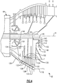
- a geared turbofan architecture with a counter-rotating low pressure compressor (LPC) 60 and counter-rotating low pressure turbine (LPT) 62 is provided, which significantly reduces a length of the low speed or inner shaft 40 as compared to a non-counter-rotating configuration, an example of which is shown in Figure 1 and in the upper half of Figure 2 .
- This non-rotating configuration in the upper half of Figure 2 is included for the purposes of a length comparison to the counter-rotating LPC and counter-rotating LPT configurations shown in the lower half of Figure 2 .
- the engine has a high pressure core, schematically indicated at 64.
- the high pressure core 64 includes the combustor 56 and the high spool 32 (i.e., the high pressure compressor 52, the high pressure turbine 54, and the high shaft 50) shown in Figure 1 .
- the high pressure compressor 52 has a high pressure core ratio of 23:1, for example. To retain this ratio, as well as providing a desired low shaft diameter and speed, a combination of the counter-rotating LPC 60 and LPT 62 is utilized as shown in the lower half of Figure 2 .
- the LPC 60 includes a counter-rotating compressor hub 70 with blade stages 72, 74, and 76 interspersed with blade stages 78 and 80 of the low speed spool 30.
- the counter-rotating compressor hub 70 may be driven by a transmission 82.
- the transmission 82 is also schematically illustrated in Figure 5 .
- the transmission 82 is an epicyclic transmission having a sun gear 84 mounted to the low shaft 40.
- a circumferential array of externally-toothed star gears 86 are in meshing engagement with the sun gear 84.
- the star gears 86 are carried on journals 88 carried by a carrier 90.
- the carrier 90 is fixedly mounted relative to an engine static structure 92.
- the static structure 92 is coupled to the low shaft 40 via multiple bearing systems 94 and 96 to permit rotation of the low shaft 40.
- the transmission 82 further includes an internally-toothed ring gear 98 encircling and in meshing engagement with the star gears 86.
- the ring gear 98 is supported relative to the static structure 92 by one or more bearing systems 100 and 102.
- the transmission 82 causes a counter-rotation of ring gear 98.
- Fan blades 104 of the fan section 22 are mounted via a hub 106 to the low shaft 40.
- low pressure compressor blades 78, 80 are also mounted to the hub 106 via a blade platform ring 108.
- the fan blades 104 and the low pressure compressor blades 78, 80 co-rotate with the low shaft 40.
- An outboard surface of the platform ring 108 locally forms an inboard boundary of a core flowpath 110.
- the blades of stages 78 and 80 extend from inboard ends fixed to the platform ring 108 to free outboard tips.
- the blades of the downstreammost stage 76 of the hub 70 are mounted to an outboard end of a support 112.
- the outboard ends of the blades of the stage 76 are secured relative to a shroud ring 114.
- An inboard surface of the shroud ring 114 forms a local outboard boundary of the core flowpath 110.
- the outboard ends of the blades of the stages 72 and 74 are mounted to the shroud ring 114.
- the support 112 is affixed to the ring gear 98 to drive rotation of the blades of stage 76 and, through the shroud ring 114, the blades of stages 72 and 74.
- the engine 20 without a counter-rotating compressor or turbine has an overall length L1 defined from a foremost surface of the fan blade 104 to an aftmost end of a turbine exhaust case 118.
- the LPC configuration 60 provides a length reduction L2 by utilizing a counter-rotating compressor architecture.
- the LPT configuration 62 provides another length reduction L3 by utilizing a counter-rotating turbine architecture.
- One example of a LPT is found in United States Publication No. 2009/0191045 A1 .
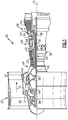
- FIGS 2 and 4 show another example of a LPT 62 having a counter-rotating configuration with a gear system 116 mounted to the turbine exhaust case 118, which contributes to the overall amount of length reduction L3 by shortening the LPT static case portion.
- the LPT 62 has an inner set of blades 120 that are directly coupled to the low shaft 40 and an outer set of blades 122 interspersed with the inner set of blades 120.
- the outer set of blades 122 rotates in an opposite direction about the axis A as compared to the inner set of blades 120.
- the inner set of blades 120 are fixed to an inner rotor 124 that directly drives the low shaft 40, i.e. the low shaft 40 and inner set of blades rotate at a common speed.
- the outer set of blades 122 are fixed to an outer rotor 126 that drives the gear system 116.
- Bearings 130, 132 rotatably support the outer rotor 126.
- Bearing 130 supports an aft end of the rotor 126 for rotation relative to the low shaft 40, while bearing 132 supports a fore end of the rotor 126 for rotation relative to a mid-turbine frame 134.
- the aft bearing 130 is a ball bearing and the fore bearing 132 is a roller bearing.
- the shaft bearing 146 and the fore bearing 132 for the outer rotor 126 are radially aligned with each other in a direction extending radially away from the axis A.
- the shaft bearing 146 is radially inward of the fore bearing 132.
- both bearings 132, 146 are roller bearings.
- the mid-turbine frame 134 comprises a static structure that extends to an outer case portion 136.
- the outer case portion 136 is attached to a LPT static case 138, which surrounds the inner 120 and outer 122 sets of blades.
- the gear system 116 includes a sun gear 140 that is driven by the outer rotor 126.
- the inner rotor 124 is coupled to the low shaft 40.
- a circumferential array of externally-toothed star gears 142 are in meshing engagement with the sun gear 140.
- the star gears 142 are supported by a carrier 144 ( Figure 4 ) that is fixed to the turbine exhaust case 118.
- a bearing 146 supports the low shaft 40 for rotation relative to the mid-turbine frame 134.
- a ring gear 148 is in meshing engagement with the star gears 142.
- the aft end of the rotor 126 drives the sun gear 140.
- the low shaft 40 includes a portion 150 that extends in a radial direction away from the axis A. This portion 150 is configured to be driven by the ring gear 148.
- the gear system has a ratio of up to 5.0:1.
- the gear system 116 is downstream of the LPT 62. Specifically, the gear system 116 is positioned aft of the interspersed blades 120, 122 and is surrounded by the turbine exhaust case 118.
- the carrier 144 for the star gears 142 is fixed to the turbine exhaust case 118 via at least one strut 152.
- This counter-rotating configuration allows the overall length of the LPT static case 138 to be shortened compared to a non-counter-rotating configuration. This results in a weight reduction as well as contributing to the desired length reduction L3.
- the gear drive is at a cooler location than if it were mounted to the mid-turbine frame.
- Other advantages of placing the gear system 116 within the turbine exhaust case 118 include providing greater strut areas for mounting and oil flow, in addition to providing scavenging, buffer air, and better serviceability.
- the low shaft 40 receives a portion of the overall driving input directly from the inner set of blades 120 and a remaining portion of the overall driving input is provided by the outer set of blades 122 via the gear system 116.
- the outer set of blades 122 is configured to rotate at a faster speed and in an opposite direction from the inner set of blades 120. Spinning the outer set of blades 122 at a higher speed takes advantage of the existing turbine disks' ability to handle higher speeds.
- This configuration provides a geared turbofan architecture with a long, slow turning low shaft 40, which enables the use of a high pressure ratio core. Further, this configuration provides for significant length reduction as compared to prior configurations.
- LPC 60 described above is just one example configuration, and that the LPT 62 described above could be utilized with various other LPC configurations. Further, the LPT 62 could also be used in a configuration that does not include a counter-rotating LPC.
- an engine has been invented that includes both a desirable high pressure core ratio, while at the same time reducing the overall engine length, thereby maximizing the engine's power density.
Landscapes
- Engineering & Computer Science (AREA)
- Chemical & Material Sciences (AREA)
- Combustion & Propulsion (AREA)
- Mechanical Engineering (AREA)
- General Engineering & Computer Science (AREA)
- Retarders (AREA)
- Control Of Turbines (AREA)
Claims (15)
- Gasturbinentriebwerk (20), umfassend:eine Welle (40), die eine Drehachse (A) definiert;einen Turbinenabschnitt (28), umfassend:dadurch gekennzeichnet, dass:einen inneren Rotor (124), der die Welle (40) direkt antreibt, wobei der innere Rotor (124) einen inneren Schaufelsatz (120) beinhaltet;einen äußeren Rotor (126), der einen äußeren Schaufelsatz (122) aufweist, der mit dem inneren Schaufelsatz (120) durchsetzt ist, wobei der äußere Rotor (126) dazu ausgelegt ist, sich in einer entgegengesetzten Richtung zu dem inneren Rotor (124) um die Drehachse (A) zu drehen; undein Getriebesystem (116), das den äußeren Rotor (126) an die Welle (40) kuppelt,d as Getriebesystem (116) dazu ausgelegt ist, den inneren Schaufelsatz (120) mit einer geringeren Drehzahl zu drehen als den äußeren Schaufelsatz (122).
- Gasturbinentriebwerk (20) nach Anspruch 1, wobei das Getriebesystem (116) an ein Turbinenabgasgehäuse (118) montiert ist.
- Gasturbinentriebwerk (20) nach Anspruch 2, wobei das Getriebesystem (116) ein Sonnenrad (140), das mit dem äußeren Rotor (126) in Eingriff steht, eine Vielzahl von Sternrädern (142) in kämmendem Eingriff mit dem Sonnenrad (140) und ein Hohlrad (148) in kämmendem Eingriff mit den Sternrädern (142) beinhaltet.
- Gasturbinentriebwerk (20) nach Anspruch 3, wobei das Sonnenrad (140) zur Drehung mit einem hinteren Ende des äußeren Rotors (126) fixiert ist.
- Gasturbinentriebwerk (20) nach Anspruch 3 oder 4, wobei die Sternräder (142) innerhalb eines Trägers (144) gestützt sind, der an dem Turbinenabgasgehäuse (118) fixiert ist.
- Gasturbinentriebwerk (20) nach Anspruch 3, 4 oder 5, wobei ein hinteres Ende der Welle (40) einen Abschnitt (150) beinhaltet, der sich von der Achse (A) radial nach außen erstreckt, um an das Hohlrad (148) gekoppelt zu werden.
- Gasturbinentriebwerk (20) nach einem der Ansprüche 2 bis 6, beinhaltend ein statisches Gehäuse (138) für eine Niederdruckturbine, das ein hinteres Ende, das mit dem Turbinenabgasgehäuse (118) verbunden ist, und ein vorderes Ende, das mit einem Turbinenzwischengehäuse (136) verbunden ist, aufweist.
- Gasturbinentriebwerk (20) nach einem der vorhergehenden Ansprüche, beinhaltend ein erstes Lager (132), das ein vorderes Ende des äußeren Rotors (126) für Drehung relativ zu einer Turbinenzwischengehäusestruktur (134) stützt, und ein zweites Lager (130), das ein hinteres Ende des äußeren Rotors (126) für Drehung relativ zu der Welle (40) stützt.
- Gasturbinentriebwerk (20) nach Anspruch 8, beinhaltend ein drittes Lager (146), das die Welle (40) für Drehung relativ zu der Turbinenzwischengehäusestruktur (134) stützt.
- Gasturbinentriebwerk (20) nach Anspruch 9, wobei das erste und dritte Lager (132, 146) Rollenlager sind und das zweite Lager (130) ein Kugellager ist.
- Gasturbinentriebwerk (20) nach Anspruch 9 oder 10, wobei das erste und dritte Lager (132, 146) im Allgemeinen relativ zu der Drehachse (A) miteinander gefluchtet sind.
- Gasturbinentriebwerk (20) nach einem der vorhergehenden Ansprüche, wobei ein vorderes Ende der Welle (40) mit einem gegenläufigen Niederdruckverdichter (60) verknüpft ist.
- Gasturbinentriebwerk (20) nach einem der vorhergehenden Ansprüche, ferner umfassend:einen Kernluftströmungsweg (110); undeinen Verdichterabschnitt (24), wobei die Welle (40) den Verdichterabschnitt (24) und den Turbinenabschnitt (28) innerhalb des Kernluftströmungswegs (110) stützt und der Turbinenabschnitt (28) eine gegenläufige Niederdruckturbine (62) beinhaltet.
- Gasturbinentriebwerk (20) nach Anspruch 13, wobei der Verdichterabschnitt (24) einen Hochdruckverdichterabschnitt beinhaltet, der ein Druckverhältnis von etwa 23:1 aufweist.
- Gasturbinentriebwerk (20) nach Anspruch 13 oder 14, wobei der Verdichterabschnitt (24) einen/den durch die Welle (40) angetriebenen gegenläufigen Niederdruckverdichter (62) beinhaltet.
Applications Claiming Priority (2)
| Application Number | Priority Date | Filing Date | Title |
|---|---|---|---|
| US13/408,281 US9011076B2 (en) | 2012-02-29 | 2012-02-29 | Counter-rotating low pressure turbine with gear system mounted to turbine exhaust case |
| PCT/US2013/026266 WO2013165524A2 (en) | 2012-02-29 | 2013-02-15 | Counter-rotating low pressure turbine with gear system mounted to turbine exhaust case |
Publications (3)
| Publication Number | Publication Date |
|---|---|
| EP2820280A2 EP2820280A2 (de) | 2015-01-07 |
| EP2820280A4 EP2820280A4 (de) | 2015-11-04 |
| EP2820280B1 true EP2820280B1 (de) | 2017-09-27 |
Family
ID=49003065
Family Applications (1)
| Application Number | Title | Priority Date | Filing Date |
|---|---|---|---|
| EP13784640.8A Active EP2820280B1 (de) | 2012-02-29 | 2013-02-15 | Gegenläufige niederdruckturbine mit am turbinenabgasgehäuse montierten getriebesystem |
Country Status (4)
| Country | Link |
|---|---|
| US (1) | US9011076B2 (de) |
| EP (1) | EP2820280B1 (de) |
| SG (1) | SG11201405076VA (de) |
| WO (1) | WO2013165524A2 (de) |
Families Citing this family (27)
| Publication number | Priority date | Publication date | Assignee | Title |
|---|---|---|---|---|
| US20130219859A1 (en) * | 2012-02-29 | 2013-08-29 | Gabriel L. Suciu | Counter rotating low pressure compressor and turbine each having a gear system |
| WO2014152101A1 (en) * | 2013-03-15 | 2014-09-25 | United Technologies Corporation | Turbofan engine bearing and gearbox arrangement |
| US20150176484A1 (en) * | 2013-12-23 | 2015-06-25 | United Technologies Corporation | Geared turbofan with a gearbox aft of a fan drive turbine |
| US9869190B2 (en) | 2014-05-30 | 2018-01-16 | General Electric Company | Variable-pitch rotor with remote counterweights |
| US10072510B2 (en) | 2014-11-21 | 2018-09-11 | General Electric Company | Variable pitch fan for gas turbine engine and method of assembling the same |
| US20160245184A1 (en) * | 2015-02-19 | 2016-08-25 | United Technologies Corporation | Geared turbine engine |
| US11225913B2 (en) | 2015-02-19 | 2022-01-18 | Raytheon Technologies Corporation | Method of providing turbine engines with different thrust ratings |
| US10100653B2 (en) | 2015-10-08 | 2018-10-16 | General Electric Company | Variable pitch fan blade retention system |
| US10823114B2 (en) | 2017-02-08 | 2020-11-03 | General Electric Company | Counter rotating turbine with reversing reduction gearbox |
| US10801442B2 (en) | 2017-02-08 | 2020-10-13 | General Electric Company | Counter rotating turbine with reversing reduction gear assembly |
| US10465606B2 (en) * | 2017-02-08 | 2019-11-05 | General Electric Company | Counter rotating turbine with reversing reduction gearbox |
| US11105200B2 (en) | 2017-07-13 | 2021-08-31 | General Electric Company | Counter rotating power turbine with reduction gearbox |
| US10914194B2 (en) | 2017-09-20 | 2021-02-09 | General Electric Company | Turbomachine with alternatingly spaced turbine rotor blades |
| US10823001B2 (en) * | 2017-09-20 | 2020-11-03 | General Electric Company | Turbomachine with alternatingly spaced turbine rotor blades |
| US10738617B2 (en) | 2017-09-20 | 2020-08-11 | General Electric Company | Turbomachine with alternatingly spaced turbine rotor blades |
| US10781717B2 (en) | 2017-09-20 | 2020-09-22 | General Electric Company | Turbomachine with alternatingly spaced turbine rotor blades |
| US11098592B2 (en) | 2017-09-20 | 2021-08-24 | General Electric Company | Turbomachine with alternatingly spaced turbine rotor blades |
| US10508546B2 (en) | 2017-09-20 | 2019-12-17 | General Electric Company | Turbomachine with alternatingly spaced turbine rotor blades |
| US10823000B2 (en) | 2017-09-20 | 2020-11-03 | General Electric Company | Turbomachine with alternatingly spaced turbine rotor blades |
| FR3088966B1 (fr) * | 2018-11-27 | 2020-11-06 | Safran Aircraft Engines | Agencement de turboréacteur double flux à réducteur épicycloïdal ou planétaire |
| US11118535B2 (en) | 2019-03-05 | 2021-09-14 | General Electric Company | Reversing gear assembly for a turbo machine |
| FR3104193B1 (fr) * | 2019-12-10 | 2021-10-29 | Safran Aircraft Engines | Recuperation d’huile de lubrification d’un reducteur de turbomachine d’aeronef |
| FR3104207B1 (fr) | 2019-12-10 | 2021-11-05 | Safran Aircraft Engines | Pressurisation d’enceintes de lubrification dans une turbomachine a turbine contrarotative |
| US11428160B2 (en) | 2020-12-31 | 2022-08-30 | General Electric Company | Gas turbine engine with interdigitated turbine and gear assembly |
| US11674435B2 (en) | 2021-06-29 | 2023-06-13 | General Electric Company | Levered counterweight feathering system |
| US11795964B2 (en) | 2021-07-16 | 2023-10-24 | General Electric Company | Levered counterweight feathering system |
| US12601271B2 (en) | 2022-10-21 | 2026-04-14 | General Electric Company | Variable pitch fan of a gas turbine engine |
Family Cites Families (30)
| Publication number | Priority date | Publication date | Assignee | Title |
|---|---|---|---|---|
| US4817382A (en) | 1985-12-31 | 1989-04-04 | The Boeing Company | Turboprop propulsion apparatus |
| US5010729A (en) | 1989-01-03 | 1991-04-30 | General Electric Company | Geared counterrotating turbine/fan propulsion system |
| US4969325A (en) | 1989-01-03 | 1990-11-13 | General Electric Company | Turbofan engine having a counterrotating partially geared fan drive turbine |
| DE3933776A1 (de) * | 1989-10-10 | 1991-04-18 | Mtu Muenchen Gmbh | Propfan-turbotriebwerk |
| US5307622A (en) | 1993-08-02 | 1994-05-03 | General Electric Company | Counterrotating turbine support assembly |
| DE19828562B4 (de) | 1998-06-26 | 2005-09-08 | Mtu Aero Engines Gmbh | Triebwerk mit gegenläufig drehenden Rotoren |
| US6158210A (en) * | 1998-12-03 | 2000-12-12 | General Electric Company | Gear driven booster |
| US6619030B1 (en) | 2002-03-01 | 2003-09-16 | General Electric Company | Aircraft engine with inter-turbine engine frame supported counter rotating low pressure turbine rotors |
| US6684626B1 (en) | 2002-07-30 | 2004-02-03 | General Electric Company | Aircraft gas turbine engine with control vanes for counter rotating low pressure turbines |
| US6763652B2 (en) | 2002-09-24 | 2004-07-20 | General Electric Company | Variable torque split aircraft gas turbine engine counter rotating low pressure turbines |
| US6763653B2 (en) | 2002-09-24 | 2004-07-20 | General Electric Company | Counter rotating fan aircraft gas turbine engine with aft booster |
| US6763654B2 (en) | 2002-09-30 | 2004-07-20 | General Electric Co. | Aircraft gas turbine engine having variable torque split counter rotating low pressure turbines and booster aft of counter rotating fans |
| GB0406174D0 (en) | 2004-03-19 | 2004-04-21 | Rolls Royce Plc | Turbine engine arrangement |
| US7186073B2 (en) | 2004-10-29 | 2007-03-06 | General Electric Company | Counter-rotating gas turbine engine and method of assembling same |
| US7334392B2 (en) | 2004-10-29 | 2008-02-26 | General Electric Company | Counter-rotating gas turbine engine and method of assembling same |
| US7752836B2 (en) * | 2005-10-19 | 2010-07-13 | General Electric Company | Gas turbine assembly and methods of assembling same |
| US7493754B2 (en) | 2005-10-19 | 2009-02-24 | General Electric Company | Gas turbine engine assembly and methods of assembling same |
| US7490460B2 (en) * | 2005-10-19 | 2009-02-17 | General Electric Company | Gas turbine engine assembly and methods of assembling same |
| US7726113B2 (en) | 2005-10-19 | 2010-06-01 | General Electric Company | Gas turbine engine assembly and methods of assembling same |
| US7490461B2 (en) | 2005-10-19 | 2009-02-17 | General Electric Company | Gas turbine engine assembly and methods of assembling same |
| US7685808B2 (en) | 2005-10-19 | 2010-03-30 | General Electric Company | Gas turbine engine assembly and methods of assembling same |
| US7950220B2 (en) | 2006-06-19 | 2011-05-31 | United Technologies Corporation | Turbine engine compressor |
| US7841165B2 (en) | 2006-10-31 | 2010-11-30 | General Electric Company | Gas turbine engine assembly and methods of assembling same |
| US7926259B2 (en) | 2006-10-31 | 2011-04-19 | General Electric Company | Turbofan engine assembly and method of assembling same |
| US7716914B2 (en) | 2006-12-21 | 2010-05-18 | General Electric Company | Turbofan engine assembly and method of assembling same |
| US8015798B2 (en) | 2007-12-13 | 2011-09-13 | United Technologies Corporation | Geared counter-rotating gas turbofan engine |
| US8292570B2 (en) | 2008-01-25 | 2012-10-23 | United Technologies Corporation | Low pressure turbine with counter-rotating drives for single spool |
| US8191352B2 (en) | 2008-12-19 | 2012-06-05 | General Electric Company | Geared differential speed counter-rotatable low pressure turbine |
| FR2940247B1 (fr) | 2008-12-19 | 2011-01-21 | Snecma | Systeme d'helices contrarotatives entrainees par un train epicycloidal offrant une repartition de couple equilibree entre les deux helices |
| US8517672B2 (en) | 2010-02-23 | 2013-08-27 | General Electric Company | Epicyclic gearbox |
-
2012
- 2012-02-29 US US13/408,281 patent/US9011076B2/en active Active
-
2013
- 2013-02-15 SG SG11201405076VA patent/SG11201405076VA/en unknown
- 2013-02-15 WO PCT/US2013/026266 patent/WO2013165524A2/en not_active Ceased
- 2013-02-15 EP EP13784640.8A patent/EP2820280B1/de active Active
Non-Patent Citations (1)
| Title |
|---|
| None * |
Also Published As
| Publication number | Publication date |
|---|---|
| WO2013165524A3 (en) | 2014-01-16 |
| EP2820280A4 (de) | 2015-11-04 |
| US20130223992A1 (en) | 2013-08-29 |
| EP2820280A2 (de) | 2015-01-07 |
| WO2013165524A2 (en) | 2013-11-07 |
| SG11201405076VA (en) | 2014-11-27 |
| US9011076B2 (en) | 2015-04-21 |
Similar Documents
| Publication | Publication Date | Title |
|---|---|---|
| EP2820280B1 (de) | Gegenläufige niederdruckturbine mit am turbinenabgasgehäuse montierten getriebesystem | |
| EP2820266B1 (de) | Gasturbinenmotor | |
| EP2820282B1 (de) | Gegenläufige niederdruckturbine mit einem an den mittelturbinenrahmen montierten getriebesystem | |
| EP2820267B1 (de) | Gegenläufiger niederdruckverdichter und turbine, beide mit einem getriebesystem | |
| EP2820281B1 (de) | Gegenläufige niederdruckturbine ohne turbinenabgasgehäuse | |
| EP2820265B1 (de) | Gegenläufige niederdruckturbine mit splittergetriebesystem | |
| EP2877725B1 (de) | Getriebefan mit innerem gegenläufig rotierendem verdichter | |
| EP2809890B1 (de) | Lageranordnung für einen gasturbinenmotor | |
| EP3036416B1 (de) | Getriebefan mit hohem schub | |
| EP3269965B1 (de) | Gasturbinenmotor mit getriebe | |
| EP3054141B1 (de) | Reduktionsgetriebe für getriebefan | |
| WO2014055103A1 (en) | Pylon shape with geared turbofan for structural stiffness | |
| EP2809937B1 (de) | Lageranordnung für eine gasturbinenmotorwelle |
Legal Events
| Date | Code | Title | Description |
|---|---|---|---|
| PUAI | Public reference made under article 153(3) epc to a published international application that has entered the european phase |
Free format text: ORIGINAL CODE: 0009012 |
|
| 17P | Request for examination filed |
Effective date: 20140922 |
|
| AK | Designated contracting states |
Kind code of ref document: A2 Designated state(s): AL AT BE BG CH CY CZ DE DK EE ES FI FR GB GR HR HU IE IS IT LI LT LU LV MC MK MT NL NO PL PT RO RS SE SI SK SM TR |
|
| AX | Request for extension of the european patent |
Extension state: BA ME |
|
| DAX | Request for extension of the european patent (deleted) | ||
| A4 | Supplementary search report drawn up and despatched |
Effective date: 20151005 |
|
| RIC1 | Information provided on ipc code assigned before grant |
Ipc: F01D 1/26 20060101ALI20150929BHEP Ipc: F02K 3/072 20060101AFI20150929BHEP Ipc: F02K 3/068 20060101ALI20150929BHEP Ipc: F01D 15/12 20060101ALI20150929BHEP Ipc: F02C 3/107 20060101ALI20150929BHEP Ipc: F02C 7/06 20060101ALI20150929BHEP Ipc: F02C 3/067 20060101ALI20150929BHEP Ipc: F02K 3/04 20060101ALI20150929BHEP Ipc: F02C 7/04 20060101ALI20150929BHEP Ipc: F02C 7/36 20060101ALI20150929BHEP |
|
| RAP1 | Party data changed (applicant data changed or rights of an application transferred) |
Owner name: UNITED TECHNOLOGIES CORPORATION |
|
| GRAP | Despatch of communication of intention to grant a patent |
Free format text: ORIGINAL CODE: EPIDOSNIGR1 |
|
| STAA | Information on the status of an ep patent application or granted ep patent |
Free format text: STATUS: GRANT OF PATENT IS INTENDED |
|
| INTG | Intention to grant announced |
Effective date: 20170411 |
|
| GRAS | Grant fee paid |
Free format text: ORIGINAL CODE: EPIDOSNIGR3 |
|
| GRAA | (expected) grant |
Free format text: ORIGINAL CODE: 0009210 |
|
| STAA | Information on the status of an ep patent application or granted ep patent |
Free format text: STATUS: THE PATENT HAS BEEN GRANTED |
|
| AK | Designated contracting states |
Kind code of ref document: B1 Designated state(s): AL AT BE BG CH CY CZ DE DK EE ES FI FR GB GR HR HU IE IS IT LI LT LU LV MC MK MT NL NO PL PT RO RS SE SI SK SM TR |
|
| REG | Reference to a national code |
Ref country code: GB Ref legal event code: FG4D |
|
| REG | Reference to a national code |
Ref country code: CH Ref legal event code: EP |
|
| REG | Reference to a national code |
Ref country code: AT Ref legal event code: REF Ref document number: 932207 Country of ref document: AT Kind code of ref document: T Effective date: 20171015 |
|
| REG | Reference to a national code |
Ref country code: IE Ref legal event code: FG4D |
|
| REG | Reference to a national code |
Ref country code: DE Ref legal event code: R096 Ref document number: 602013027205 Country of ref document: DE |
|
| REG | Reference to a national code |
Ref country code: FR Ref legal event code: PLFP Year of fee payment: 6 |
|
| PG25 | Lapsed in a contracting state [announced via postgrant information from national office to epo] |
Ref country code: NO Free format text: LAPSE BECAUSE OF FAILURE TO SUBMIT A TRANSLATION OF THE DESCRIPTION OR TO PAY THE FEE WITHIN THE PRESCRIBED TIME-LIMIT Effective date: 20171227 Ref country code: HR Free format text: LAPSE BECAUSE OF FAILURE TO SUBMIT A TRANSLATION OF THE DESCRIPTION OR TO PAY THE FEE WITHIN THE PRESCRIBED TIME-LIMIT Effective date: 20170927 Ref country code: LT Free format text: LAPSE BECAUSE OF FAILURE TO SUBMIT A TRANSLATION OF THE DESCRIPTION OR TO PAY THE FEE WITHIN THE PRESCRIBED TIME-LIMIT Effective date: 20170927 Ref country code: SE Free format text: LAPSE BECAUSE OF FAILURE TO SUBMIT A TRANSLATION OF THE DESCRIPTION OR TO PAY THE FEE WITHIN THE PRESCRIBED TIME-LIMIT Effective date: 20170927 Ref country code: FI Free format text: LAPSE BECAUSE OF FAILURE TO SUBMIT A TRANSLATION OF THE DESCRIPTION OR TO PAY THE FEE WITHIN THE PRESCRIBED TIME-LIMIT Effective date: 20170927 |
|
| REG | Reference to a national code |
Ref country code: NL Ref legal event code: MP Effective date: 20170927 |
|
| REG | Reference to a national code |
Ref country code: LT Ref legal event code: MG4D |
|
| REG | Reference to a national code |
Ref country code: AT Ref legal event code: MK05 Ref document number: 932207 Country of ref document: AT Kind code of ref document: T Effective date: 20170927 |
|
| PG25 | Lapsed in a contracting state [announced via postgrant information from national office to epo] |
Ref country code: RS Free format text: LAPSE BECAUSE OF FAILURE TO SUBMIT A TRANSLATION OF THE DESCRIPTION OR TO PAY THE FEE WITHIN THE PRESCRIBED TIME-LIMIT Effective date: 20170927 Ref country code: LV Free format text: LAPSE BECAUSE OF FAILURE TO SUBMIT A TRANSLATION OF THE DESCRIPTION OR TO PAY THE FEE WITHIN THE PRESCRIBED TIME-LIMIT Effective date: 20170927 Ref country code: GR Free format text: LAPSE BECAUSE OF FAILURE TO SUBMIT A TRANSLATION OF THE DESCRIPTION OR TO PAY THE FEE WITHIN THE PRESCRIBED TIME-LIMIT Effective date: 20171228 Ref country code: BG Free format text: LAPSE BECAUSE OF FAILURE TO SUBMIT A TRANSLATION OF THE DESCRIPTION OR TO PAY THE FEE WITHIN THE PRESCRIBED TIME-LIMIT Effective date: 20171227 |
|
| PG25 | Lapsed in a contracting state [announced via postgrant information from national office to epo] |
Ref country code: NL Free format text: LAPSE BECAUSE OF FAILURE TO SUBMIT A TRANSLATION OF THE DESCRIPTION OR TO PAY THE FEE WITHIN THE PRESCRIBED TIME-LIMIT Effective date: 20170927 |
|
| PG25 | Lapsed in a contracting state [announced via postgrant information from national office to epo] |
Ref country code: ES Free format text: LAPSE BECAUSE OF FAILURE TO SUBMIT A TRANSLATION OF THE DESCRIPTION OR TO PAY THE FEE WITHIN THE PRESCRIBED TIME-LIMIT Effective date: 20170927 Ref country code: RO Free format text: LAPSE BECAUSE OF FAILURE TO SUBMIT A TRANSLATION OF THE DESCRIPTION OR TO PAY THE FEE WITHIN THE PRESCRIBED TIME-LIMIT Effective date: 20170927 Ref country code: CZ Free format text: LAPSE BECAUSE OF FAILURE TO SUBMIT A TRANSLATION OF THE DESCRIPTION OR TO PAY THE FEE WITHIN THE PRESCRIBED TIME-LIMIT Effective date: 20170927 |
|
| PG25 | Lapsed in a contracting state [announced via postgrant information from national office to epo] |
Ref country code: AT Free format text: LAPSE BECAUSE OF FAILURE TO SUBMIT A TRANSLATION OF THE DESCRIPTION OR TO PAY THE FEE WITHIN THE PRESCRIBED TIME-LIMIT Effective date: 20170927 Ref country code: IS Free format text: LAPSE BECAUSE OF FAILURE TO SUBMIT A TRANSLATION OF THE DESCRIPTION OR TO PAY THE FEE WITHIN THE PRESCRIBED TIME-LIMIT Effective date: 20180127 Ref country code: EE Free format text: LAPSE BECAUSE OF FAILURE TO SUBMIT A TRANSLATION OF THE DESCRIPTION OR TO PAY THE FEE WITHIN THE PRESCRIBED TIME-LIMIT Effective date: 20170927 Ref country code: SK Free format text: LAPSE BECAUSE OF FAILURE TO SUBMIT A TRANSLATION OF THE DESCRIPTION OR TO PAY THE FEE WITHIN THE PRESCRIBED TIME-LIMIT Effective date: 20170927 Ref country code: SM Free format text: LAPSE BECAUSE OF FAILURE TO SUBMIT A TRANSLATION OF THE DESCRIPTION OR TO PAY THE FEE WITHIN THE PRESCRIBED TIME-LIMIT Effective date: 20170927 Ref country code: IT Free format text: LAPSE BECAUSE OF FAILURE TO SUBMIT A TRANSLATION OF THE DESCRIPTION OR TO PAY THE FEE WITHIN THE PRESCRIBED TIME-LIMIT Effective date: 20170927 |
|
| REG | Reference to a national code |
Ref country code: DE Ref legal event code: R097 Ref document number: 602013027205 Country of ref document: DE |
|
| PG25 | Lapsed in a contracting state [announced via postgrant information from national office to epo] |
Ref country code: DK Free format text: LAPSE BECAUSE OF FAILURE TO SUBMIT A TRANSLATION OF THE DESCRIPTION OR TO PAY THE FEE WITHIN THE PRESCRIBED TIME-LIMIT Effective date: 20170927 |
|
| PLBE | No opposition filed within time limit |
Free format text: ORIGINAL CODE: 0009261 |
|
| STAA | Information on the status of an ep patent application or granted ep patent |
Free format text: STATUS: NO OPPOSITION FILED WITHIN TIME LIMIT |
|
| PG25 | Lapsed in a contracting state [announced via postgrant information from national office to epo] |
Ref country code: PL Free format text: LAPSE BECAUSE OF FAILURE TO SUBMIT A TRANSLATION OF THE DESCRIPTION OR TO PAY THE FEE WITHIN THE PRESCRIBED TIME-LIMIT Effective date: 20170927 |
|
| 26N | No opposition filed |
Effective date: 20180628 |
|
| REG | Reference to a national code |
Ref country code: CH Ref legal event code: PL |
|
| PG25 | Lapsed in a contracting state [announced via postgrant information from national office to epo] |
Ref country code: MC Free format text: LAPSE BECAUSE OF FAILURE TO SUBMIT A TRANSLATION OF THE DESCRIPTION OR TO PAY THE FEE WITHIN THE PRESCRIBED TIME-LIMIT Effective date: 20170927 |
|
| REG | Reference to a national code |
Ref country code: IE Ref legal event code: MM4A |
|
| REG | Reference to a national code |
Ref country code: BE Ref legal event code: MM Effective date: 20180228 |
|
| PG25 | Lapsed in a contracting state [announced via postgrant information from national office to epo] |
Ref country code: CH Free format text: LAPSE BECAUSE OF NON-PAYMENT OF DUE FEES Effective date: 20180228 Ref country code: SI Free format text: LAPSE BECAUSE OF FAILURE TO SUBMIT A TRANSLATION OF THE DESCRIPTION OR TO PAY THE FEE WITHIN THE PRESCRIBED TIME-LIMIT Effective date: 20170927 Ref country code: LU Free format text: LAPSE BECAUSE OF NON-PAYMENT OF DUE FEES Effective date: 20180215 Ref country code: LI Free format text: LAPSE BECAUSE OF NON-PAYMENT OF DUE FEES Effective date: 20180228 |
|
| PG25 | Lapsed in a contracting state [announced via postgrant information from national office to epo] |
Ref country code: IE Free format text: LAPSE BECAUSE OF NON-PAYMENT OF DUE FEES Effective date: 20180215 |
|
| PG25 | Lapsed in a contracting state [announced via postgrant information from national office to epo] |
Ref country code: BE Free format text: LAPSE BECAUSE OF NON-PAYMENT OF DUE FEES Effective date: 20180228 |
|
| PG25 | Lapsed in a contracting state [announced via postgrant information from national office to epo] |
Ref country code: MT Free format text: LAPSE BECAUSE OF NON-PAYMENT OF DUE FEES Effective date: 20180215 |
|
| PG25 | Lapsed in a contracting state [announced via postgrant information from national office to epo] |
Ref country code: TR Free format text: LAPSE BECAUSE OF FAILURE TO SUBMIT A TRANSLATION OF THE DESCRIPTION OR TO PAY THE FEE WITHIN THE PRESCRIBED TIME-LIMIT Effective date: 20170927 |
|
| PG25 | Lapsed in a contracting state [announced via postgrant information from national office to epo] |
Ref country code: HU Free format text: LAPSE BECAUSE OF FAILURE TO SUBMIT A TRANSLATION OF THE DESCRIPTION OR TO PAY THE FEE WITHIN THE PRESCRIBED TIME-LIMIT; INVALID AB INITIO Effective date: 20130215 Ref country code: PT Free format text: LAPSE BECAUSE OF FAILURE TO SUBMIT A TRANSLATION OF THE DESCRIPTION OR TO PAY THE FEE WITHIN THE PRESCRIBED TIME-LIMIT Effective date: 20170927 |
|
| PG25 | Lapsed in a contracting state [announced via postgrant information from national office to epo] |
Ref country code: MK Free format text: LAPSE BECAUSE OF NON-PAYMENT OF DUE FEES Effective date: 20170927 Ref country code: CY Free format text: LAPSE BECAUSE OF FAILURE TO SUBMIT A TRANSLATION OF THE DESCRIPTION OR TO PAY THE FEE WITHIN THE PRESCRIBED TIME-LIMIT Effective date: 20170927 |
|
| PG25 | Lapsed in a contracting state [announced via postgrant information from national office to epo] |
Ref country code: AL Free format text: LAPSE BECAUSE OF FAILURE TO SUBMIT A TRANSLATION OF THE DESCRIPTION OR TO PAY THE FEE WITHIN THE PRESCRIBED TIME-LIMIT Effective date: 20170927 |
|
| REG | Reference to a national code |
Ref country code: DE Ref legal event code: R081 Ref document number: 602013027205 Country of ref document: DE Owner name: RAYTHEON TECHNOLOGIES CORPORATION (N.D.GES.D.S, US Free format text: FORMER OWNER: UNITED TECHNOLOGIES CORPORATION, FARMINGTON, CONN., US Ref country code: DE Ref legal event code: R081 Ref document number: 602013027205 Country of ref document: DE Owner name: RTX CORPORATION (N.D.GES.D. STAATES DELAWARE),, US Free format text: FORMER OWNER: UNITED TECHNOLOGIES CORPORATION, FARMINGTON, CONN., US |
|
| P01 | Opt-out of the competence of the unified patent court (upc) registered |
Effective date: 20230520 |
|
| REG | Reference to a national code |
Ref country code: DE Ref legal event code: R081 Ref document number: 602013027205 Country of ref document: DE Owner name: RTX CORPORATION (N.D.GES.D. STAATES DELAWARE),, US Free format text: FORMER OWNER: RAYTHEON TECHNOLOGIES CORPORATION (N.D.GES.D.STAATES DELAWARE), ARLINGTON, VA, US |
|
| PGFP | Annual fee paid to national office [announced via postgrant information from national office to epo] |
Ref country code: GB Payment date: 20260122 Year of fee payment: 14 |
|
| PGFP | Annual fee paid to national office [announced via postgrant information from national office to epo] |
Ref country code: DE Payment date: 20260121 Year of fee payment: 14 |
|
| PGFP | Annual fee paid to national office [announced via postgrant information from national office to epo] |
Ref country code: FR Payment date: 20260121 Year of fee payment: 14 |