EP2809937B1 - Lageranordnung für eine gasturbinenmotorwelle - Google Patents
Lageranordnung für eine gasturbinenmotorwelle Download PDFInfo
- Publication number
- EP2809937B1 EP2809937B1 EP13805198.2A EP13805198A EP2809937B1 EP 2809937 B1 EP2809937 B1 EP 2809937B1 EP 13805198 A EP13805198 A EP 13805198A EP 2809937 B1 EP2809937 B1 EP 2809937B1
- Authority
- EP
- European Patent Office
- Prior art keywords
- shaft
- hub
- bearing
- gas turbine
- turbine engine
- Prior art date
- Legal status (The legal status is an assumption and is not a legal conclusion. Google has not performed a legal analysis and makes no representation as to the accuracy of the status listed.)
- Active
Links
Images

Classifications
-
- F—MECHANICAL ENGINEERING; LIGHTING; HEATING; WEAPONS; BLASTING
- F01—MACHINES OR ENGINES IN GENERAL; ENGINE PLANTS IN GENERAL; STEAM ENGINES
- F01D—NON-POSITIVE DISPLACEMENT MACHINES OR ENGINES, e.g. STEAM TURBINES
- F01D25/00—Component parts, details, or accessories, not provided for in, or of interest apart from, other groups
- F01D25/16—Arrangement of bearings; Supporting or mounting bearings in casings
- F01D25/162—Bearing supports
-
- F—MECHANICAL ENGINEERING; LIGHTING; HEATING; WEAPONS; BLASTING
- F05—INDEXING SCHEMES RELATING TO ENGINES OR PUMPS IN VARIOUS SUBCLASSES OF CLASSES F01-F04
- F05D—INDEXING SCHEME FOR ASPECTS RELATING TO NON-POSITIVE-DISPLACEMENT MACHINES OR ENGINES, GAS-TURBINES OR JET-PROPULSION PLANTS
- F05D2260/00—Function
- F05D2260/50—Kinematic linkage, i.e. transmission of position
- F05D2260/53—Kinematic linkage, i.e. transmission of position using gears
Definitions
- This disclosure relates to a gas turbine engine bearing arrangement for a shaft.
- the bearing arrangement relates to a low speed shaft.
- a typical jet engine has multiple shafts or spools that transmit torque between turbine and compressor sections of the engine.
- Each shaft is typically supported by a first bearing at a forward end of the shaft and a second bearing at an aft end of the shaft.
- the first bearing for example, is a ball bearing that reacts to both axial and radial loads.
- the second bearing for example, is a roller bearing or journal bearing that reacts only to radial loads. This bearing arrangement fully constrains the shaft except for rotation, and axial movement of one free end is permitted to accommodate engine axial growth.
- the gas turbine engine includes a compressor section with a compressor case having a first compressor case portion defining a compressor case flow path and a second compressor case portion removably secured to the first compressor case portion. A portion of the second inlet case portion is surrounded by the first compressor case portion.
- the shaft comprises a main shaft and a hub secured to the main shaft.
- the compressor section includes a rotor mounted to the hub, with the hub supporting the first and the second bearings.
- the geared architecture is coupled to the hub.
- the shaft includes a main shaft, a hub secured to the main shaft, and a flex shaft having at least one bellow.
- the flex shaft is secured to the hub at an aft end and is coupled to the geared architecture at a fore end.
- the geared architecture includes a sun gear supported on the fore end, a torque frame supporting multiple circumferentially arranged star gears intermeshing with the sun gear, and a ring gear meshing with the star gears.
- the aft end of the flex shaft is coupled to the hub at a connection interface, and the connection interface is positioned aft of the second bearing.
- the hub includes a first hub end and a second hub end, with the second bearing being directly supported by the first hub end and the first bearing being supported by the second hub end.
- the connection interface is positioned between the first and second hub ends.
- the first bearing is a ball bearing and the second bearing is a roller bearing.
- the ball bearing is located aft of the roller bearing, and the ball and roller bearings are generally aligned with each other in an axial direction defined by the shaft.
- any of the above including a compressor section with a plurality of vanes and a rotor supporting a plurality of blades interspersed with the plurality of vanes, and wherein the first and second bearings are positioned radially between the shaft and the blades.
- a gas turbine engine including a core housing providing a core flow path and a shaft supporting a compressor section arranged within the core flow path.
- First and second bearings support the shaft for rotation relative to the core housing.
- the first and second bearings are positioned within a common bearing compartment positioned within the compressor section.
- the shaft includes a main shaft, a hub secured to the main shaft, and a flex shaft having at least one bellow.
- the flex shaft is secured to the hub at an aft end and is coupled to a geared architecture at a fore end.
- the first and second bearings are directly supported by the hub.
- FIG. 1 schematically illustrates a gas turbine engine 20.
- the gas turbine engine 20 is disclosed herein as a two-spool turbofan that generally incorporates a fan section 22, a compressor section 24, a combustor section 26 and a turbine section 28.
- Alternative engines might include an augmentor section (not shown) among other systems or features.
- the fan section 22 drives air along a bypass flowpath while the compressor section 24 drives air along a core flowpath for compression and communication into the combustor section 26 then expansion through the turbine section 28.
- FIG. 1 schematically illustrates a gas turbine engine 20.
- the gas turbine engine 20 is disclosed herein as a two-spool turbofan that generally incorporates a fan section 22, a compressor section 24, a combustor section 26 and a turbine section 28.
- Alternative engines might include an augmentor section (not shown) among other systems or features.
- the fan section 22 drives air along a bypass flowpath while the compressor section 24 drives air along a core flowpath for compression and communication into the combustor section 26
- the engine 20 generally includes a low speed spool 30 and a high speed spool 32 mounted for rotation about an engine central longitudinal axis A relative to an engine static structure 36 via several bearing systems 38. It should be understood that various bearing systems 38 at various locations may alternatively or additionally be provided.
- the low speed spool 30 generally includes an inner shaft 40 that interconnects a fan 42, a low pressure compressor 44 and a low pressure turbine 46.
- the inner shaft 40 is connected to the fan 42 through a geared architecture 48 to drive the fan 42 at a lower speed than the low speed spool 30.
- the high speed spool 32 includes an outer shaft 50 that interconnects a high pressure compressor 52 and high pressure turbine 54.
- a combustor 56 is arranged between the high pressure compressor 52 and the high pressure turbine 54.
- a mid-turbine frame 57 of the engine static structure 36 is arranged generally between the high pressure turbine 54 and the low pressure turbine 46.
- the mid-turbine frame 57 supports one or more bearing systems 38 in the turbine section 28.
- the inner shaft 40 and the outer shaft 50 are concentric and rotate via bearing systems 38 about the engine central longitudinal axis A, which is collinear with their longitudinal axes.
- the core airflow is compressed by the low pressure compressor 44 then the high pressure compressor 52, mixed and burned with fuel in the combustor 56, then expanded over the high pressure turbine 54 and low pressure turbine 46.
- the mid-turbine frame 57 includes airfoils 59 which are in the core airflow path.
- the turbines 46, 54 rotationally drive the respective low speed spool 30 and high speed spool 32 in response to the expansion.
- the engine 20 in one example is a high-bypass geared aircraft engine.
- the engine 20 bypass ratio is greater than about six (6), with an example embodiment being greater than ten (10), the geared architecture 48 is an epicyclic gear train, such as a planetary gear system or other gear system, with a gear reduction ratio of greater than about 2.3 and the low pressure turbine 46 has a pressure ratio that is greater than about 5.
- the engine 20 bypass ratio is greater than about ten (10:1)
- the fan diameter is significantly larger than that of the low pressure compressor 44
- the low pressure turbine 46 has a pressure ratio that is greater than about 5:1.
- Low pressure turbine 46 pressure ratio is pressure measured prior to inlet of low pressure turbine 46 as related to the pressure at the outlet of the low pressure turbine 46 prior to an exhaust nozzle.
- the geared architecture 48 may be an epicycle gear train, such as a planetary gear system or other gear system, with a gear reduction ratio of greater than about 2.5:1. It should be understood, however, that the above parameters are only exemplary of one embodiment of a geared architecture engine and that the present invention is applicable to other gas turbine engines including direct drive turbofans.
- the fan section 22 of the engine 20 is designed for a particular flight condition -- typically cruise at about 0.8 Mach and about 10688 m (35,000 feet).
- the flight condition of 0.8 Mach and 10688 m (35,000 feet), with the engine at its best fuel consumption - also known as "bucket cruise Thrust Specific Fuel Consumption ('TSFC')" - is the industry standard parameter of lbm of fuel being burned divided by lbf of thrust the engine produces at that minimum point.
- "Low fan pressure ratio” is the pressure ratio across the fan blade alone, without a Fan Exit Guide Vane (“FEGV”) system.
- the low fan pressure ratio as disclosed herein according to one non-limiting embodiment is less than about 1.45.
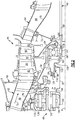
- a core housing 60 includes an inlet case 62 and a compressor case 64 that respectively provide an inlet case flowpath 66 and a compressor case flowpath 68. Together, the inlet and compressor case flowpaths 66, 68, in part, define a core flowpath through the engine 20, which directs a core flow C F .
- the inlet case 62 and compressor case 64 are comprised of multiple components.
- the compressor case 64 includes at least first 70 and second 72 compressor case portions, which are removably secured to one another at a connection interface 74.
- the inlet case 62 includes a first inlet case portion 76 and a second inlet case portion 78 that are removably secured to one another at a connection interface 80.
- the first inlet case portion 76 defines the inlet case flowpath 66 and the first compressor case portion 70 defines the compressor case flowpath 68.
- the low pressure compressor 44 includes multiple compressor stages arranged between the inlet 66 and compressor 68 case flowpaths. Rotating blades 82 of the compressor stages are coupled to the inner shaft 40 by a rotor 84. Vanes 86 of the compressor stages are fixed to the compressor case 64 and are alternated with the blades 82.
- the inner shaft 40 is constructed of multiple components that include, for example, a main shaft 88, a hub 90, and a flex shaft 92 with at least one bellow 94.
- the rotor 84 and hub 90 are clamped to the main shaft 88 with a nut 96.
- the flex shaft 92 is coupled to the hub 90 at a connection interface 98.
- the flex shaft 92 has a fore end 100 and an aft end 102.
- the aft end 102 is splined, for example, to the hub 90 at the connection interface 98.
- the fore end 100 is coupled to the geared architecture 48.
- the bellows 94 in the flex shaft 92 accommodate vibration in the geared architecture 48.
- the fore end 100 of the flex shaft 92 is splined to and supports a sun gear 104 of the geared architecture 48.
- the geared architecture 48 also includes star gears 106 arranged circumferentially about and intermeshing with the sun gear 104.
- a ring gear 108 is arranged circumferentially about and intermeshes with the star gears 106.
- a fan structure 110 connects the ring gear 108 and the fan 42 ( Figure 1 ).
- a torque frame 112 supports the star gears 106 and grounds the star gears 106 to the housing 60. In operation, the inner shaft 40 rotationally drives the fan structure 110 with the rotating ring gear 108 through the grounded star gears 106.
- the second inlet case portion 78 and torque frame 112 are secured to the first inlet case portion 76 at the connection interface 80.
- Struts 114 are arranged upstream of the vanes 86 to provide additional support at the connection interface 80.
- the hub 90 includes a fore hub end 116 and an aft hub end 118.
- the connection interface 98 to the flex shaft 92 is at a location that is between the fore 116 and aft 118 hub ends.
- the aft hub end 118 overlaps the rotor 84 such that at least a portion of the rotor 84 is located radially between the hub 90 and the main shaft 88.
- the shaft 40 rotates about the engine central longitudinal axis A.
- a bearing compartment is formed between the shaft 40 and the second inlet case portion 78.
- the bearing compartment is formed between the hub 90 of the shaft 40 and the second inlet case portion 78.
- a first bearing 122 and a second bearing 124 support the shaft 40 for rotation relative to the inlet case 62.
- the first 122 and second 124 bearings are both positioned with the bearing compartment, i.e. the bearings are located within a common bearing compartment.
- a portion of the second inlet case portion 78 extends into and is surrounded by the first compressor case portion 70.
- the first 122 and second 124 bearings include outer race portions that are mounted to the second inlet case portion 78.
- the blades 82 and vanes 86 of the low pressure compressor 44 are positioned radially outwardly relative to the first 122 and second 124 bearings.
- the inner shaft 40 comprises the main shaft 88 and the hub 90 which is secured to the main shaft 88.
- the rotor 84 is mounted to the aft end 118 of the hub 90.
- the hub 90 directly supports the inner races of the first 122 and the second 124 bearings.
- the fore hub end 116 supports the second bearing 124 and the aft hub end 118 supports the first bearing 122.
- the aft end 102 of the flex shaft 92 is coupled to the hub 90 at the connection interface 98, which is positioned aft of the second bearing 124.
- the first bearing 122 is a ball bearing and the second bearing 124 is a roller bearing.
- the ball bearing is located aft of the roller bearing.
- the ball bearing constrains the inner shaft 40 against axial and radial movement at a forward portion of the inner shaft 40.
- the roller bearing reacts only to radial loads.
- first 122 and second 124 bearings are generally aligned with each other in an axial direction defined by the shaft 40.
- the fore hub end 116 is spaced further radially away from the axis A than the aft hub end 118.
- a transition portion 126 of the hub 90 connects the radially outer fore hub end 116 to the radially inner aft hub end 118.
- the second inlet case portion 78 includes a fore flange portion 128 that supports the second bearing 124 and an aft flange portion 130 that supports the first bearing 122.
- the fore flange portion 128 is radially closer to the axis A than the aft flange portion 130.
- the inner shaft 40 of the geared fan engine can be subjected to very high rpm loads, which may cause rotor dynamic issues. These dynamic issues increase the longer and smaller in diameter the shaft becomes. Adding an additional bearing at a fore end of the shaft facilitates control of shaft dynamic modes and allows the use of longer and smaller diameter shafts. By adding another bearing in the existing bearing compartment extra carbon seals are not required. Further, minimal weight is added to the system due to the location of the additional bearing relative to the shaft.
Landscapes
- Engineering & Computer Science (AREA)
- Mechanical Engineering (AREA)
- General Engineering & Computer Science (AREA)
- Structures Of Non-Positive Displacement Pumps (AREA)
Claims (13)
- Gasturbinentriebwerk (20), umfassend:eine Welle (40), die eine Drehachse (A) definiert;ein erstes Lager (122), das die Welle (40) relativ zu einem Einlassgehäuse (62) drehbar lagert; undein zweites Lager (124), das die Welle (40) ebenfalls relativ zu dem Einlassgehäuse (62) drehbar lagert;wobei das erste Lager (122) innerhalb einer Lagerkammer (120) angeordnet ist, die zwischen der Welle (40) und dem Einlassgehäuse (62) gebildet ist, und das zweite Lager (124) ebenfalls in der Lagerkammer (120) angeordnet ist;eine verzahnte Struktur (48), die an die Welle (40) gekoppelt ist, und einen Fan (42), der an die verzahnte Struktur (48) gekoppelt ist und von dieser drehbar angetrieben wird;wobei das Einlassgehäuse (62) einen ersten Einlassgehäuseabschnitt (76), der einen Einlassgehäuse-Strömungsweg (66) definiert, und einen zweiten Einlassgehäuseabschnitt (78), der abnehmbar an dem ersten Einlassgehäuseabschnitt (76) befestigt ist, umfasst, wobei das erste und das zweite Lager (122, 124) an dem zweiten Einlassgehäuseabschnitt (78) montiert sind; dadurch gekennzeichnet, dass der erste Einlassgehäuseabschnitt (76) sich stromaufwärts von dem zweiten Einlassgehäuseabschnitt (78) erstreckt, um die gezahnte Struktur (48) zu umgeben.
- Gasturbinentriebwerk nach Anspruch 1, beinhaltend einen Verdichterteil (24) mit einem Verdichtergehäuse (64), das einen ersten Verdichtergehäuseabschnitt (70), der einen Verdichtergehäuse-Strömungsweg (68) definiert, und einen zweiten Verdichtergehäuseabschnitt (72) aufweist, der abnehmbar an dem ersten Verdichtergehäuseabschnitt (70) befestigt ist, und wobei ein Abschnitt des zweiten Einlassgehäuseabschnitts (78) von einem Abschnitt des Verdichterteils (24) umgeben ist.
- Gasturbinentriebwerk nach Anspruch 2, wobei die Welle (40) eine Hauptwelle (88) und eine Nabe (90), die an der Hauptwelle (88) befestigt ist, umfasst, und wobei der Verdichterteil (24) einen Rotor (84) beinhaltet, der an der Nabe (90) montiert ist, wobei die Nabe (90) das erste und das zweite Lager (122, 124) trägt.
- Gasturbinentriebwerk nach Anspruch 3, wobei die verzahnte Struktur (48) an die Nabe (90) gekoppelt ist.
- Gasturbinentriebwerk nach Anspruch 4, wobei die Welle (40) eine biegsame Welle (92) beinhaltet, die mindestens einen Faltenbalg (94) beinhaltet, wobei die biegsame Welle (92) an der Nabe (90) an einem hinteren Ende (102) befestigt ist und an die verzahnte Struktur (48) an einem vorderen Ende (100) gekoppelt ist.
- Gasturbinentriebwerk nach Anspruch 5, wobei die verzahnte Struktur (48) ein an dem vorderen Ende (100) der biegsamen Welle (92) getragenes Sonnenrad (104), einen Drehmomentrahmen (112), der mehrere in Umfangsrichtung angeordnete, mit dem Sonnenrad (104) verzahnte Planetenräder (106) trägt, und ein mit den Planetenrädern (106) verzahntes Hohlrad (108) beinhaltet.
- Gasturbinentriebwerk nach Anspruch 5 oder 6, wobei das hintere Ende (102) der biegsamen Welle (92) an einer Verbindungsschnittstelle (98) an die Nabe (90) gekoppelt ist und wobei die Verbindungsschnittstelle (98) hinter dem zweiten Lager (124) angeordnet ist.
- Gasturbinentriebwerk nach Anspruch 7, wobei die Nabe (90) ein vorderes Nabenende (116) und ein hinteres Nabenende (118) beinhaltet, wobei das zweite Lager (124) direkt von dem vorderen Nabenende (116) getragen wird und das erste Lager (122) von dem hinteren Nabenende (118) getragen wird, wobei die Verbindungsschnittstelle (98) zwischen dem vorderen und dem hinteren Nabenende (116, 118) angeordnet ist.
- Gasturbinentriebwerk nach einem der vorangehenden Ansprüche, beinhaltend einen Verdichterteil (24) mit einer Vielzahl von Leitschaufeln (86) und einem Rotor (84), der eine Vielzahl von Laufschaufeln (82) trägt, die mit der Vielzahl von Leitschaufeln (86) durchsetzt sind, und wobei das erste und das zweite Lager (122, 124) radial zwischen der Welle (40) und den Flügeln (82) angeordnet sind.
- Gasturbinentriebwerk nach einem der vorangehenden Ansprüche, wobei die Welle (40) eine Hauptwelle (88), eine an der Hauptwelle (88) befestigte Nabe (90) und eine biegsame Welle (92) mit mindestens einem Faltenbalg (94) beinhaltet, und wobei der Faltenbalg (94) an der Nabe (90) an einem hinteren Ende (102) befestigt ist und an eine verzahnte Struktur (48) an einem vorderen Ende (100) gekoppelt ist, und wobei das erste und das zweite Lager (122, 124) direkt von der Nabe (90) getragen werden.
- Gasturbinentriebwerk nach einem der vorangehenden Ansprüche, wobei das erste Lager (122) ein Kugellager ist und das zweite Lager (124) ein Wälzlager ist.
- Gasturbinentriebwerk nach Anspruch 11, wobei das Kugellager (122) sich hinter dem Wälzlager (124) befindet.
- Gasturbinentriebwerk nach Anspruch 12, wobei das Kugel- und das Wälzlager (122, 124) allgemein in eine axiale Richtung aufeinander ausgerichtet sind, die von der Welle (40) definiert wird.
Applications Claiming Priority (2)
| Application Number | Priority Date | Filing Date | Title |
|---|---|---|---|
| US13/362,237 US10145266B2 (en) | 2012-01-31 | 2012-01-31 | Gas turbine engine shaft bearing arrangement |
| PCT/US2013/023556 WO2013187938A1 (en) | 2012-01-31 | 2013-01-29 | Gas turbine engine shaft bearing arrangement |
Publications (3)
| Publication Number | Publication Date |
|---|---|
| EP2809937A1 EP2809937A1 (de) | 2014-12-10 |
| EP2809937A4 EP2809937A4 (de) | 2015-10-07 |
| EP2809937B1 true EP2809937B1 (de) | 2018-07-18 |
Family
ID=48870368
Family Applications (1)
| Application Number | Title | Priority Date | Filing Date |
|---|---|---|---|
| EP13805198.2A Active EP2809937B1 (de) | 2012-01-31 | 2013-01-29 | Lageranordnung für eine gasturbinenmotorwelle |
Country Status (3)
| Country | Link |
|---|---|
| US (1) | US10145266B2 (de) |
| EP (1) | EP2809937B1 (de) |
| WO (1) | WO2013187938A1 (de) |
Families Citing this family (3)
| Publication number | Priority date | Publication date | Assignee | Title |
|---|---|---|---|---|
| US8834095B2 (en) * | 2011-06-24 | 2014-09-16 | United Technologies Corporation | Integral bearing support and centering spring assembly for a gas turbine engine |
| US9702404B2 (en) | 2015-10-28 | 2017-07-11 | United Technologies Corporation | Integral centering spring and bearing support and method of supporting multiple damped bearings |
| US11306726B2 (en) | 2019-03-11 | 2022-04-19 | Emerson Climate Technologies, Inc. | Foil bearing assembly and compressor including same |
Family Cites Families (36)
| Publication number | Priority date | Publication date | Assignee | Title |
|---|---|---|---|---|
| US3287906A (en) | 1965-07-20 | 1966-11-29 | Gen Motors Corp | Cooled gas turbine vanes |
| GB1318629A (en) * | 1970-11-21 | 1973-05-31 | Secr Defence | Gas turbine engine |
| US3792586A (en) * | 1973-01-22 | 1974-02-19 | Avco Corp | Bearing assembly systems |
| US3925979A (en) * | 1973-10-29 | 1975-12-16 | Gen Electric | Anti-icing system for a gas turbine engine |
| GB1516041A (en) | 1977-02-14 | 1978-06-28 | Secr Defence | Multistage axial flow compressor stators |
| GB2041090A (en) | 1979-01-31 | 1980-09-03 | Rolls Royce | By-pass gas turbine engines |
| US4251987A (en) * | 1979-08-22 | 1981-02-24 | General Electric Company | Differential geared engine |
| GB2195712B (en) * | 1986-10-08 | 1990-08-29 | Rolls Royce Plc | A turbofan gas turbine engine |
| GB8630754D0 (en) * | 1986-12-23 | 1987-02-04 | Rolls Royce Plc | Turbofan gas turbine engine |
| US4916894A (en) * | 1989-01-03 | 1990-04-17 | General Electric Company | High bypass turbofan engine having a partially geared fan drive turbine |
| US5433674A (en) * | 1994-04-12 | 1995-07-18 | United Technologies Corporation | Coupling system for a planetary gear train |
| EP0839285B1 (de) | 1994-12-14 | 2001-07-18 | United Technologies Corporation | Druckkontrolle eines verdichters mittels messung eines asymetrischen luftstroms |
| US6491497B1 (en) | 2000-09-22 | 2002-12-10 | General Electric Company | Method and apparatus for supporting rotor assemblies during unbalances |
| US6846158B2 (en) * | 2002-09-06 | 2005-01-25 | General Electric Company | Method and apparatus for varying the critical speed of a shaft |
| US7021042B2 (en) * | 2002-12-13 | 2006-04-04 | United Technologies Corporation | Geartrain coupling for a turbofan engine |
| FR2856430B1 (fr) | 2003-06-20 | 2005-09-23 | Snecma Moteurs | Agencement de supports de paliers pour arbre tournant d'un moteur d'aeronef et moteur d'aeronef equipe d'un tel agencement |
| FR2866074B1 (fr) * | 2004-02-11 | 2006-04-28 | Snecma Moteurs | Architecture d'un turboreacteur ayant une double soufflante a l'avant |
| US7097413B2 (en) * | 2004-05-12 | 2006-08-29 | United Technologies Corporation | Bearing support |
| US7309210B2 (en) * | 2004-12-17 | 2007-12-18 | United Technologies Corporation | Turbine engine rotor stack |
| WO2007038674A1 (en) | 2005-09-28 | 2007-04-05 | Entrotech Composites, Llc | Braid-reinforced composites and processes for their preparation |
| US7490460B2 (en) * | 2005-10-19 | 2009-02-17 | General Electric Company | Gas turbine engine assembly and methods of assembling same |
| US7704178B2 (en) * | 2006-07-05 | 2010-04-27 | United Technologies Corporation | Oil baffle for gas turbine fan drive gear system |
| US7694505B2 (en) | 2006-07-31 | 2010-04-13 | General Electric Company | Gas turbine engine assembly and method of assembling same |
| WO2008105815A2 (en) * | 2006-08-22 | 2008-09-04 | Rolls-Royce North American Technologies, Inc. | Gas turbine engine with intermediate speed booster |
| FR2907861B1 (fr) | 2006-10-26 | 2008-12-26 | Snecma Sa | Agencement de palier d'un arbre tournant et turboreacteur equipe d'un tel agencement |
| US7832193B2 (en) * | 2006-10-27 | 2010-11-16 | General Electric Company | Gas turbine engine assembly and methods of assembling same |
| US7966806B2 (en) | 2006-10-31 | 2011-06-28 | General Electric Company | Turbofan engine assembly and method of assembling same |
| US7882693B2 (en) | 2006-11-29 | 2011-02-08 | General Electric Company | Turbofan engine assembly and method of assembling same |
| US7716914B2 (en) * | 2006-12-21 | 2010-05-18 | General Electric Company | Turbofan engine assembly and method of assembling same |
| US8017188B2 (en) | 2007-04-17 | 2011-09-13 | General Electric Company | Methods of making articles having toughened and untoughened regions |
| US7955046B2 (en) | 2007-09-25 | 2011-06-07 | United Technologies Corporation | Gas turbine engine front architecture modularity |
| US8511986B2 (en) * | 2007-12-10 | 2013-08-20 | United Technologies Corporation | Bearing mounting system in a low pressure turbine |
| US8191352B2 (en) | 2008-12-19 | 2012-06-05 | General Electric Company | Geared differential speed counter-rotatable low pressure turbine |
| FR2944558B1 (fr) | 2009-04-17 | 2014-05-02 | Snecma | Moteur a turbine a gaz double corps pourvu d'un palier de turbine bp supplementaire. |
| US8172716B2 (en) | 2009-06-25 | 2012-05-08 | United Technologies Corporation | Epicyclic gear system with superfinished journal bearing |
| US8672801B2 (en) | 2009-11-30 | 2014-03-18 | United Technologies Corporation | Mounting system for a planetary gear train in a gas turbine engine |
-
2012
- 2012-01-31 US US13/362,237 patent/US10145266B2/en active Active
-
2013
- 2013-01-29 WO PCT/US2013/023556 patent/WO2013187938A1/en not_active Ceased
- 2013-01-29 EP EP13805198.2A patent/EP2809937B1/de active Active
Non-Patent Citations (1)
| Title |
|---|
| None * |
Also Published As
| Publication number | Publication date |
|---|---|
| US10145266B2 (en) | 2018-12-04 |
| EP2809937A1 (de) | 2014-12-10 |
| WO2013187938A1 (en) | 2013-12-19 |
| EP2809937A4 (de) | 2015-10-07 |
| US20130195646A1 (en) | 2013-08-01 |
Similar Documents
| Publication | Publication Date | Title |
|---|---|---|
| EP2809890B1 (de) | Lageranordnung für einen gasturbinenmotor | |
| EP3473834B1 (de) | Konfiguration eines wellenlagers für eine gasturbine | |
| US11149689B2 (en) | Gas turbine engine shaft bearing configuration | |
| EP2877725B1 (de) | Getriebefan mit innerem gegenläufig rotierendem verdichter | |
| US10190497B2 (en) | Counter-rotating low pressure turbine without turbine exhaust case | |
| EP2809902B1 (de) | Hintere lageranordnung für einen gasturbinenmotor | |
| US20150089959A1 (en) | Gas turbine engine shaft bearing configuration | |
| EP3054141B1 (de) | Reduktionsgetriebe für getriebefan | |
| EP3027864A1 (de) | Konfiguration eines wellenlagers für eine gasturbine | |
| EP2809937B1 (de) | Lageranordnung für eine gasturbinenmotorwelle | |
| EP3081768B1 (de) | Konfiguration eines wellenlagers einer gasturbine |
Legal Events
| Date | Code | Title | Description |
|---|---|---|---|
| PUAI | Public reference made under article 153(3) epc to a published international application that has entered the european phase |
Free format text: ORIGINAL CODE: 0009012 |
|
| 17P | Request for examination filed |
Effective date: 20140821 |
|
| AK | Designated contracting states |
Kind code of ref document: A1 Designated state(s): AL AT BE BG CH CY CZ DE DK EE ES FI FR GB GR HR HU IE IS IT LI LT LU LV MC MK MT NL NO PL PT RO RS SE SI SK SM TR |
|
| AX | Request for extension of the european patent |
Extension state: BA ME |
|
| DAX | Request for extension of the european patent (deleted) | ||
| RA4 | Supplementary search report drawn up and despatched (corrected) |
Effective date: 20150902 |
|
| RIC1 | Information provided on ipc code assigned before grant |
Ipc: F02K 3/04 20060101AFI20150828BHEP Ipc: F01D 25/16 20060101ALI20150828BHEP |
|
| RAP1 | Party data changed (applicant data changed or rights of an application transferred) |
Owner name: UNITED TECHNOLOGIES CORPORATION |
|
| STAA | Information on the status of an ep patent application or granted ep patent |
Free format text: STATUS: EXAMINATION IS IN PROGRESS |
|
| 17Q | First examination report despatched |
Effective date: 20161129 |
|
| GRAP | Despatch of communication of intention to grant a patent |
Free format text: ORIGINAL CODE: EPIDOSNIGR1 |
|
| STAA | Information on the status of an ep patent application or granted ep patent |
Free format text: STATUS: GRANT OF PATENT IS INTENDED |
|
| INTG | Intention to grant announced |
Effective date: 20180109 |
|
| GRAS | Grant fee paid |
Free format text: ORIGINAL CODE: EPIDOSNIGR3 |
|
| GRAJ | Information related to disapproval of communication of intention to grant by the applicant or resumption of examination proceedings by the epo deleted |
Free format text: ORIGINAL CODE: EPIDOSDIGR1 |
|
| GRAL | Information related to payment of fee for publishing/printing deleted |
Free format text: ORIGINAL CODE: EPIDOSDIGR3 |
|
| STAA | Information on the status of an ep patent application or granted ep patent |
Free format text: STATUS: EXAMINATION IS IN PROGRESS |
|
| GRAR | Information related to intention to grant a patent recorded |
Free format text: ORIGINAL CODE: EPIDOSNIGR71 |
|
| STAA | Information on the status of an ep patent application or granted ep patent |
Free format text: STATUS: GRANT OF PATENT IS INTENDED |
|
| GRAA | (expected) grant |
Free format text: ORIGINAL CODE: 0009210 |
|
| STAA | Information on the status of an ep patent application or granted ep patent |
Free format text: STATUS: THE PATENT HAS BEEN GRANTED |
|
| INTC | Intention to grant announced (deleted) | ||
| AK | Designated contracting states |
Kind code of ref document: B1 Designated state(s): AL AT BE BG CH CY CZ DE DK EE ES FI FR GB GR HR HU IE IS IT LI LT LU LV MC MK MT NL NO PL PT RO RS SE SI SK SM TR |
|
| INTG | Intention to grant announced |
Effective date: 20180611 |
|
| REG | Reference to a national code |
Ref country code: GB Ref legal event code: FG4D |
|
| REG | Reference to a national code |
Ref country code: CH Ref legal event code: EP |
|
| REG | Reference to a national code |
Ref country code: IE Ref legal event code: FG4D |
|
| REG | Reference to a national code |
Ref country code: AT Ref legal event code: REF Ref document number: 1019634 Country of ref document: AT Kind code of ref document: T Effective date: 20180815 |
|
| REG | Reference to a national code |
Ref country code: DE Ref legal event code: R096 Ref document number: 602013040561 Country of ref document: DE |
|
| REG | Reference to a national code |
Ref country code: NL Ref legal event code: MP Effective date: 20180718 |
|
| REG | Reference to a national code |
Ref country code: LT Ref legal event code: MG4D |
|
| REG | Reference to a national code |
Ref country code: AT Ref legal event code: MK05 Ref document number: 1019634 Country of ref document: AT Kind code of ref document: T Effective date: 20180718 |
|
| PG25 | Lapsed in a contracting state [announced via postgrant information from national office to epo] |
Ref country code: NL Free format text: LAPSE BECAUSE OF FAILURE TO SUBMIT A TRANSLATION OF THE DESCRIPTION OR TO PAY THE FEE WITHIN THE PRESCRIBED TIME-LIMIT Effective date: 20180718 |
|
| PG25 | Lapsed in a contracting state [announced via postgrant information from national office to epo] |
Ref country code: FI Free format text: LAPSE BECAUSE OF FAILURE TO SUBMIT A TRANSLATION OF THE DESCRIPTION OR TO PAY THE FEE WITHIN THE PRESCRIBED TIME-LIMIT Effective date: 20180718 Ref country code: BG Free format text: LAPSE BECAUSE OF FAILURE TO SUBMIT A TRANSLATION OF THE DESCRIPTION OR TO PAY THE FEE WITHIN THE PRESCRIBED TIME-LIMIT Effective date: 20181018 Ref country code: PL Free format text: LAPSE BECAUSE OF FAILURE TO SUBMIT A TRANSLATION OF THE DESCRIPTION OR TO PAY THE FEE WITHIN THE PRESCRIBED TIME-LIMIT Effective date: 20180718 Ref country code: LT Free format text: LAPSE BECAUSE OF FAILURE TO SUBMIT A TRANSLATION OF THE DESCRIPTION OR TO PAY THE FEE WITHIN THE PRESCRIBED TIME-LIMIT Effective date: 20180718 Ref country code: NO Free format text: LAPSE BECAUSE OF FAILURE TO SUBMIT A TRANSLATION OF THE DESCRIPTION OR TO PAY THE FEE WITHIN THE PRESCRIBED TIME-LIMIT Effective date: 20181018 Ref country code: SE Free format text: LAPSE BECAUSE OF FAILURE TO SUBMIT A TRANSLATION OF THE DESCRIPTION OR TO PAY THE FEE WITHIN THE PRESCRIBED TIME-LIMIT Effective date: 20180718 Ref country code: AT Free format text: LAPSE BECAUSE OF FAILURE TO SUBMIT A TRANSLATION OF THE DESCRIPTION OR TO PAY THE FEE WITHIN THE PRESCRIBED TIME-LIMIT Effective date: 20180718 Ref country code: IS Free format text: LAPSE BECAUSE OF FAILURE TO SUBMIT A TRANSLATION OF THE DESCRIPTION OR TO PAY THE FEE WITHIN THE PRESCRIBED TIME-LIMIT Effective date: 20181118 Ref country code: GR Free format text: LAPSE BECAUSE OF FAILURE TO SUBMIT A TRANSLATION OF THE DESCRIPTION OR TO PAY THE FEE WITHIN THE PRESCRIBED TIME-LIMIT Effective date: 20181019 Ref country code: RS Free format text: LAPSE BECAUSE OF FAILURE TO SUBMIT A TRANSLATION OF THE DESCRIPTION OR TO PAY THE FEE WITHIN THE PRESCRIBED TIME-LIMIT Effective date: 20180718 |
|
| PG25 | Lapsed in a contracting state [announced via postgrant information from national office to epo] |
Ref country code: AL Free format text: LAPSE BECAUSE OF FAILURE TO SUBMIT A TRANSLATION OF THE DESCRIPTION OR TO PAY THE FEE WITHIN THE PRESCRIBED TIME-LIMIT Effective date: 20180718 Ref country code: HR Free format text: LAPSE BECAUSE OF FAILURE TO SUBMIT A TRANSLATION OF THE DESCRIPTION OR TO PAY THE FEE WITHIN THE PRESCRIBED TIME-LIMIT Effective date: 20180718 Ref country code: LV Free format text: LAPSE BECAUSE OF FAILURE TO SUBMIT A TRANSLATION OF THE DESCRIPTION OR TO PAY THE FEE WITHIN THE PRESCRIBED TIME-LIMIT Effective date: 20180718 |
|
| REG | Reference to a national code |
Ref country code: DE Ref legal event code: R097 Ref document number: 602013040561 Country of ref document: DE |
|
| PG25 | Lapsed in a contracting state [announced via postgrant information from national office to epo] |
Ref country code: CZ Free format text: LAPSE BECAUSE OF FAILURE TO SUBMIT A TRANSLATION OF THE DESCRIPTION OR TO PAY THE FEE WITHIN THE PRESCRIBED TIME-LIMIT Effective date: 20180718 Ref country code: IT Free format text: LAPSE BECAUSE OF FAILURE TO SUBMIT A TRANSLATION OF THE DESCRIPTION OR TO PAY THE FEE WITHIN THE PRESCRIBED TIME-LIMIT Effective date: 20180718 Ref country code: EE Free format text: LAPSE BECAUSE OF FAILURE TO SUBMIT A TRANSLATION OF THE DESCRIPTION OR TO PAY THE FEE WITHIN THE PRESCRIBED TIME-LIMIT Effective date: 20180718 Ref country code: RO Free format text: LAPSE BECAUSE OF FAILURE TO SUBMIT A TRANSLATION OF THE DESCRIPTION OR TO PAY THE FEE WITHIN THE PRESCRIBED TIME-LIMIT Effective date: 20180718 Ref country code: ES Free format text: LAPSE BECAUSE OF FAILURE TO SUBMIT A TRANSLATION OF THE DESCRIPTION OR TO PAY THE FEE WITHIN THE PRESCRIBED TIME-LIMIT Effective date: 20180718 |
|
| PLBE | No opposition filed within time limit |
Free format text: ORIGINAL CODE: 0009261 |
|
| STAA | Information on the status of an ep patent application or granted ep patent |
Free format text: STATUS: NO OPPOSITION FILED WITHIN TIME LIMIT |
|
| PG25 | Lapsed in a contracting state [announced via postgrant information from national office to epo] |
Ref country code: SK Free format text: LAPSE BECAUSE OF FAILURE TO SUBMIT A TRANSLATION OF THE DESCRIPTION OR TO PAY THE FEE WITHIN THE PRESCRIBED TIME-LIMIT Effective date: 20180718 Ref country code: SM Free format text: LAPSE BECAUSE OF FAILURE TO SUBMIT A TRANSLATION OF THE DESCRIPTION OR TO PAY THE FEE WITHIN THE PRESCRIBED TIME-LIMIT Effective date: 20180718 Ref country code: DK Free format text: LAPSE BECAUSE OF FAILURE TO SUBMIT A TRANSLATION OF THE DESCRIPTION OR TO PAY THE FEE WITHIN THE PRESCRIBED TIME-LIMIT Effective date: 20180718 |
|
| 26N | No opposition filed |
Effective date: 20190423 |
|
| PG25 | Lapsed in a contracting state [announced via postgrant information from national office to epo] |
Ref country code: MC Free format text: LAPSE BECAUSE OF FAILURE TO SUBMIT A TRANSLATION OF THE DESCRIPTION OR TO PAY THE FEE WITHIN THE PRESCRIBED TIME-LIMIT Effective date: 20180718 Ref country code: SI Free format text: LAPSE BECAUSE OF FAILURE TO SUBMIT A TRANSLATION OF THE DESCRIPTION OR TO PAY THE FEE WITHIN THE PRESCRIBED TIME-LIMIT Effective date: 20180718 |
|
| REG | Reference to a national code |
Ref country code: CH Ref legal event code: PL |
|
| PG25 | Lapsed in a contracting state [announced via postgrant information from national office to epo] |
Ref country code: LU Free format text: LAPSE BECAUSE OF NON-PAYMENT OF DUE FEES Effective date: 20190129 |
|
| REG | Reference to a national code |
Ref country code: BE Ref legal event code: MM Effective date: 20190131 |
|
| REG | Reference to a national code |
Ref country code: IE Ref legal event code: MM4A |
|
| PG25 | Lapsed in a contracting state [announced via postgrant information from national office to epo] |
Ref country code: BE Free format text: LAPSE BECAUSE OF NON-PAYMENT OF DUE FEES Effective date: 20190131 |
|
| PG25 | Lapsed in a contracting state [announced via postgrant information from national office to epo] |
Ref country code: LI Free format text: LAPSE BECAUSE OF NON-PAYMENT OF DUE FEES Effective date: 20190131 Ref country code: CH Free format text: LAPSE BECAUSE OF NON-PAYMENT OF DUE FEES Effective date: 20190131 |
|
| PG25 | Lapsed in a contracting state [announced via postgrant information from national office to epo] |
Ref country code: IE Free format text: LAPSE BECAUSE OF NON-PAYMENT OF DUE FEES Effective date: 20190129 |
|
| PG25 | Lapsed in a contracting state [announced via postgrant information from national office to epo] |
Ref country code: TR Free format text: LAPSE BECAUSE OF FAILURE TO SUBMIT A TRANSLATION OF THE DESCRIPTION OR TO PAY THE FEE WITHIN THE PRESCRIBED TIME-LIMIT Effective date: 20180718 |
|
| PG25 | Lapsed in a contracting state [announced via postgrant information from national office to epo] |
Ref country code: MT Free format text: LAPSE BECAUSE OF NON-PAYMENT OF DUE FEES Effective date: 20190129 Ref country code: PT Free format text: LAPSE BECAUSE OF FAILURE TO SUBMIT A TRANSLATION OF THE DESCRIPTION OR TO PAY THE FEE WITHIN THE PRESCRIBED TIME-LIMIT Effective date: 20181118 |
|
| PG25 | Lapsed in a contracting state [announced via postgrant information from national office to epo] |
Ref country code: CY Free format text: LAPSE BECAUSE OF FAILURE TO SUBMIT A TRANSLATION OF THE DESCRIPTION OR TO PAY THE FEE WITHIN THE PRESCRIBED TIME-LIMIT Effective date: 20180718 |
|
| PG25 | Lapsed in a contracting state [announced via postgrant information from national office to epo] |
Ref country code: HU Free format text: LAPSE BECAUSE OF FAILURE TO SUBMIT A TRANSLATION OF THE DESCRIPTION OR TO PAY THE FEE WITHIN THE PRESCRIBED TIME-LIMIT; INVALID AB INITIO Effective date: 20130129 |
|
| PG25 | Lapsed in a contracting state [announced via postgrant information from national office to epo] |
Ref country code: MK Free format text: LAPSE BECAUSE OF FAILURE TO SUBMIT A TRANSLATION OF THE DESCRIPTION OR TO PAY THE FEE WITHIN THE PRESCRIBED TIME-LIMIT Effective date: 20180718 |
|
| REG | Reference to a national code |
Ref country code: DE Ref legal event code: R081 Ref document number: 602013040561 Country of ref document: DE Owner name: RAYTHEON TECHNOLOGIES CORPORATION (N.D.GES.D.S, US Free format text: FORMER OWNER: UNITED TECHNOLOGIES CORPORATION, FARMINGTON, CONN., US Ref country code: DE Ref legal event code: R081 Ref document number: 602013040561 Country of ref document: DE Owner name: RTX CORPORATION (N.D.GES.D. STAATES DELAWARE),, US Free format text: FORMER OWNER: UNITED TECHNOLOGIES CORPORATION, FARMINGTON, CONN., US |
|
| P01 | Opt-out of the competence of the unified patent court (upc) registered |
Effective date: 20230520 |
|
| REG | Reference to a national code |
Ref country code: DE Ref legal event code: R081 Ref document number: 602013040561 Country of ref document: DE Owner name: RTX CORPORATION (N.D.GES.D. STAATES DELAWARE),, US Free format text: FORMER OWNER: RAYTHEON TECHNOLOGIES CORPORATION (N.D.GES.D.STAATES DELAWARE), ARLINGTON, VA, US |
|
| PGFP | Annual fee paid to national office [announced via postgrant information from national office to epo] |
Ref country code: GB Payment date: 20251220 Year of fee payment: 14 |
|
| PGFP | Annual fee paid to national office [announced via postgrant information from national office to epo] |
Ref country code: FR Payment date: 20251217 Year of fee payment: 14 |
|
| PGFP | Annual fee paid to national office [announced via postgrant information from national office to epo] |
Ref country code: DE Payment date: 20251217 Year of fee payment: 14 |