EP2819728B1 - Compensating for variations in air density in a pressure support device - Google Patents
Compensating for variations in air density in a pressure support device Download PDFInfo
- Publication number
- EP2819728B1 EP2819728B1 EP13718628.4A EP13718628A EP2819728B1 EP 2819728 B1 EP2819728 B1 EP 2819728B1 EP 13718628 A EP13718628 A EP 13718628A EP 2819728 B1 EP2819728 B1 EP 2819728B1
- Authority
- EP
- European Patent Office
- Prior art keywords
- ambient
- support device
- pressure support
- pressure
- ambient air
- Prior art date
- Legal status (The legal status is an assumption and is not a legal conclusion. Google has not performed a legal analysis and makes no representation as to the accuracy of the status listed.)
- Active
Links
- 239000012080 ambient air Substances 0.000 claims description 56
- 239000003570 air Substances 0.000 claims description 47
- 238000004590 computer program Methods 0.000 claims description 7
- 230000007958 sleep Effects 0.000 claims description 6
- 239000007789 gas Substances 0.000 description 21
- 238000000034 method Methods 0.000 description 18
- 238000002560 therapeutic procedure Methods 0.000 description 12
- XLYOFNOQVPJJNP-UHFFFAOYSA-N water Substances O XLYOFNOQVPJJNP-UHFFFAOYSA-N 0.000 description 12
- 238000012545 processing Methods 0.000 description 11
- 239000012530 fluid Substances 0.000 description 5
- 230000008569 process Effects 0.000 description 5
- 230000000241 respiratory effect Effects 0.000 description 4
- 230000029058 respiratory gaseous exchange Effects 0.000 description 4
- 238000013459 approach Methods 0.000 description 3
- QVGXLLKOCUKJST-UHFFFAOYSA-N atomic oxygen Chemical compound [O] QVGXLLKOCUKJST-UHFFFAOYSA-N 0.000 description 3
- 230000007246 mechanism Effects 0.000 description 3
- 208000001797 obstructive sleep apnea Diseases 0.000 description 3
- 239000001301 oxygen Substances 0.000 description 3
- 229910052760 oxygen Inorganic materials 0.000 description 3
- 230000036760 body temperature Effects 0.000 description 2
- 238000001514 detection method Methods 0.000 description 2
- 208000037265 diseases, disorders, signs and symptoms Diseases 0.000 description 2
- 208000035475 disorder Diseases 0.000 description 2
- 230000007613 environmental effect Effects 0.000 description 2
- 230000002685 pulmonary effect Effects 0.000 description 2
- 208000023504 respiratory system disease Diseases 0.000 description 2
- 230000004044 response Effects 0.000 description 2
- 229920006395 saturated elastomer Polymers 0.000 description 2
- 230000035945 sensitivity Effects 0.000 description 2
- 238000004448 titration Methods 0.000 description 2
- 206010021079 Hypopnoea Diseases 0.000 description 1
- 208000019693 Lung disease Diseases 0.000 description 1
- 208000004166 Obesity Hypoventilation Syndrome Diseases 0.000 description 1
- 206010035004 Pickwickian syndrome Diseases 0.000 description 1
- 208000004756 Respiratory Insufficiency Diseases 0.000 description 1
- 206010041235 Snoring Diseases 0.000 description 1
- 230000003444 anaesthetic effect Effects 0.000 description 1
- 208000008784 apnea Diseases 0.000 description 1
- 238000009530 blood pressure measurement Methods 0.000 description 1
- 238000004422 calculation algorithm Methods 0.000 description 1
- 238000004364 calculation method Methods 0.000 description 1
- 238000004891 communication Methods 0.000 description 1
- 230000001419 dependent effect Effects 0.000 description 1
- 238000010438 heat treatment Methods 0.000 description 1
- 230000010365 information processing Effects 0.000 description 1
- 230000003434 inspiratory effect Effects 0.000 description 1
- 210000004072 lung Anatomy 0.000 description 1
- 238000004519 manufacturing process Methods 0.000 description 1
- 230000007721 medicinal effect Effects 0.000 description 1
- 239000000203 mixture Substances 0.000 description 1
- 238000012986 modification Methods 0.000 description 1
- 230000004048 modification Effects 0.000 description 1
- 230000003287 optical effect Effects 0.000 description 1
- 201000004193 respiratory failure Diseases 0.000 description 1
- 210000002345 respiratory system Anatomy 0.000 description 1
- 239000000523 sample Substances 0.000 description 1
- 230000001360 synchronised effect Effects 0.000 description 1
- 208000011580 syndromic disease Diseases 0.000 description 1
- 230000001225 therapeutic effect Effects 0.000 description 1
- 230000007704 transition Effects 0.000 description 1
- 238000011282 treatment Methods 0.000 description 1
Images
Classifications
-
- A—HUMAN NECESSITIES
- A61—MEDICAL OR VETERINARY SCIENCE; HYGIENE
- A61M—DEVICES FOR INTRODUCING MEDIA INTO, OR ONTO, THE BODY; DEVICES FOR TRANSDUCING BODY MEDIA OR FOR TAKING MEDIA FROM THE BODY; DEVICES FOR PRODUCING OR ENDING SLEEP OR STUPOR
- A61M16/00—Devices for influencing the respiratory system of patients by gas treatment, e.g. ventilators; Tracheal tubes
- A61M16/0003—Accessories therefor, e.g. sensors, vibrators, negative pressure
-
- A—HUMAN NECESSITIES
- A61—MEDICAL OR VETERINARY SCIENCE; HYGIENE
- A61M—DEVICES FOR INTRODUCING MEDIA INTO, OR ONTO, THE BODY; DEVICES FOR TRANSDUCING BODY MEDIA OR FOR TAKING MEDIA FROM THE BODY; DEVICES FOR PRODUCING OR ENDING SLEEP OR STUPOR
- A61M16/00—Devices for influencing the respiratory system of patients by gas treatment, e.g. ventilators; Tracheal tubes
- A61M16/021—Devices for influencing the respiratory system of patients by gas treatment, e.g. ventilators; Tracheal tubes operated by electrical means
- A61M16/022—Control means therefor
- A61M16/024—Control means therefor including calculation means, e.g. using a processor
- A61M16/026—Control means therefor including calculation means, e.g. using a processor specially adapted for predicting, e.g. for determining an information representative of a flow limitation during a ventilation cycle by using a root square technique or a regression analysis
-
- A—HUMAN NECESSITIES
- A61—MEDICAL OR VETERINARY SCIENCE; HYGIENE
- A61M—DEVICES FOR INTRODUCING MEDIA INTO, OR ONTO, THE BODY; DEVICES FOR TRANSDUCING BODY MEDIA OR FOR TAKING MEDIA FROM THE BODY; DEVICES FOR PRODUCING OR ENDING SLEEP OR STUPOR
- A61M16/00—Devices for influencing the respiratory system of patients by gas treatment, e.g. ventilators; Tracheal tubes
- A61M16/0051—Devices for influencing the respiratory system of patients by gas treatment, e.g. ventilators; Tracheal tubes with alarm devices
-
- A—HUMAN NECESSITIES
- A61—MEDICAL OR VETERINARY SCIENCE; HYGIENE
- A61M—DEVICES FOR INTRODUCING MEDIA INTO, OR ONTO, THE BODY; DEVICES FOR TRANSDUCING BODY MEDIA OR FOR TAKING MEDIA FROM THE BODY; DEVICES FOR PRODUCING OR ENDING SLEEP OR STUPOR
- A61M16/00—Devices for influencing the respiratory system of patients by gas treatment, e.g. ventilators; Tracheal tubes
- A61M16/0057—Pumps therefor
-
- A—HUMAN NECESSITIES
- A61—MEDICAL OR VETERINARY SCIENCE; HYGIENE
- A61M—DEVICES FOR INTRODUCING MEDIA INTO, OR ONTO, THE BODY; DEVICES FOR TRANSDUCING BODY MEDIA OR FOR TAKING MEDIA FROM THE BODY; DEVICES FOR PRODUCING OR ENDING SLEEP OR STUPOR
- A61M16/00—Devices for influencing the respiratory system of patients by gas treatment, e.g. ventilators; Tracheal tubes
- A61M16/06—Respiratory or anaesthetic masks
-
- A—HUMAN NECESSITIES
- A61—MEDICAL OR VETERINARY SCIENCE; HYGIENE
- A61M—DEVICES FOR INTRODUCING MEDIA INTO, OR ONTO, THE BODY; DEVICES FOR TRANSDUCING BODY MEDIA OR FOR TAKING MEDIA FROM THE BODY; DEVICES FOR PRODUCING OR ENDING SLEEP OR STUPOR
- A61M16/00—Devices for influencing the respiratory system of patients by gas treatment, e.g. ventilators; Tracheal tubes
- A61M16/08—Bellows; Connecting tubes ; Water traps; Patient circuits
- A61M16/0875—Connecting tubes
-
- A—HUMAN NECESSITIES
- A61—MEDICAL OR VETERINARY SCIENCE; HYGIENE
- A61M—DEVICES FOR INTRODUCING MEDIA INTO, OR ONTO, THE BODY; DEVICES FOR TRANSDUCING BODY MEDIA OR FOR TAKING MEDIA FROM THE BODY; DEVICES FOR PRODUCING OR ENDING SLEEP OR STUPOR
- A61M16/00—Devices for influencing the respiratory system of patients by gas treatment, e.g. ventilators; Tracheal tubes
- A61M16/10—Preparation of respiratory gases or vapours
- A61M16/14—Preparation of respiratory gases or vapours by mixing different fluids, one of them being in a liquid phase
- A61M16/16—Devices to humidify the respiration air
- A61M16/161—Devices to humidify the respiration air with means for measuring the humidity
-
- A—HUMAN NECESSITIES
- A61—MEDICAL OR VETERINARY SCIENCE; HYGIENE
- A61M—DEVICES FOR INTRODUCING MEDIA INTO, OR ONTO, THE BODY; DEVICES FOR TRANSDUCING BODY MEDIA OR FOR TAKING MEDIA FROM THE BODY; DEVICES FOR PRODUCING OR ENDING SLEEP OR STUPOR
- A61M16/00—Devices for influencing the respiratory system of patients by gas treatment, e.g. ventilators; Tracheal tubes
- A61M16/0057—Pumps therefor
- A61M16/0066—Blowers or centrifugal pumps
- A61M16/0069—Blowers or centrifugal pumps the speed thereof being controlled by respiratory parameters, e.g. by inhalation
-
- A—HUMAN NECESSITIES
- A61—MEDICAL OR VETERINARY SCIENCE; HYGIENE
- A61M—DEVICES FOR INTRODUCING MEDIA INTO, OR ONTO, THE BODY; DEVICES FOR TRANSDUCING BODY MEDIA OR FOR TAKING MEDIA FROM THE BODY; DEVICES FOR PRODUCING OR ENDING SLEEP OR STUPOR
- A61M16/00—Devices for influencing the respiratory system of patients by gas treatment, e.g. ventilators; Tracheal tubes
- A61M16/10—Preparation of respiratory gases or vapours
- A61M16/105—Filters
- A61M16/106—Filters in a path
- A61M16/1065—Filters in a path in the expiratory path
-
- A—HUMAN NECESSITIES
- A61—MEDICAL OR VETERINARY SCIENCE; HYGIENE
- A61M—DEVICES FOR INTRODUCING MEDIA INTO, OR ONTO, THE BODY; DEVICES FOR TRANSDUCING BODY MEDIA OR FOR TAKING MEDIA FROM THE BODY; DEVICES FOR PRODUCING OR ENDING SLEEP OR STUPOR
- A61M2205/00—General characteristics of the apparatus
- A61M2205/33—Controlling, regulating or measuring
- A61M2205/3331—Pressure; Flow
- A61M2205/3337—Controlling, regulating pressure or flow by means of a valve by-passing a pump
-
- A—HUMAN NECESSITIES
- A61—MEDICAL OR VETERINARY SCIENCE; HYGIENE
- A61M—DEVICES FOR INTRODUCING MEDIA INTO, OR ONTO, THE BODY; DEVICES FOR TRANSDUCING BODY MEDIA OR FOR TAKING MEDIA FROM THE BODY; DEVICES FOR PRODUCING OR ENDING SLEEP OR STUPOR
- A61M2205/00—General characteristics of the apparatus
- A61M2205/33—Controlling, regulating or measuring
- A61M2205/3331—Pressure; Flow
- A61M2205/3341—Pressure; Flow stabilising pressure or flow to avoid excessive variation
-
- A—HUMAN NECESSITIES
- A61—MEDICAL OR VETERINARY SCIENCE; HYGIENE
- A61M—DEVICES FOR INTRODUCING MEDIA INTO, OR ONTO, THE BODY; DEVICES FOR TRANSDUCING BODY MEDIA OR FOR TAKING MEDIA FROM THE BODY; DEVICES FOR PRODUCING OR ENDING SLEEP OR STUPOR
- A61M2205/00—General characteristics of the apparatus
- A61M2205/33—Controlling, regulating or measuring
- A61M2205/3331—Pressure; Flow
- A61M2205/3358—Measuring barometric pressure, e.g. for compensation
-
- A—HUMAN NECESSITIES
- A61—MEDICAL OR VETERINARY SCIENCE; HYGIENE
- A61M—DEVICES FOR INTRODUCING MEDIA INTO, OR ONTO, THE BODY; DEVICES FOR TRANSDUCING BODY MEDIA OR FOR TAKING MEDIA FROM THE BODY; DEVICES FOR PRODUCING OR ENDING SLEEP OR STUPOR
- A61M2205/00—General characteristics of the apparatus
- A61M2205/33—Controlling, regulating or measuring
- A61M2205/3368—Temperature
- A61M2205/3372—Temperature compensation
-
- A—HUMAN NECESSITIES
- A61—MEDICAL OR VETERINARY SCIENCE; HYGIENE
- A61M—DEVICES FOR INTRODUCING MEDIA INTO, OR ONTO, THE BODY; DEVICES FOR TRANSDUCING BODY MEDIA OR FOR TAKING MEDIA FROM THE BODY; DEVICES FOR PRODUCING OR ENDING SLEEP OR STUPOR
- A61M2205/00—General characteristics of the apparatus
- A61M2205/50—General characteristics of the apparatus with microprocessors or computers
- A61M2205/502—User interfaces, e.g. screens or keyboards
-
- A—HUMAN NECESSITIES
- A61—MEDICAL OR VETERINARY SCIENCE; HYGIENE
- A61M—DEVICES FOR INTRODUCING MEDIA INTO, OR ONTO, THE BODY; DEVICES FOR TRANSDUCING BODY MEDIA OR FOR TAKING MEDIA FROM THE BODY; DEVICES FOR PRODUCING OR ENDING SLEEP OR STUPOR
- A61M2205/00—General characteristics of the apparatus
- A61M2205/50—General characteristics of the apparatus with microprocessors or computers
- A61M2205/52—General characteristics of the apparatus with microprocessors or computers with memories providing a history of measured variating parameters of apparatus or patient
Definitions
- the present disclosure relates to compensating for variations in air density in a pressure support device.
- a medical disorder or to diagnose, treat, or monitor the condition of a subject using medical equipment.
- a pulmonary or respiratory disorder such as obstructive sleep apnea (OSA)
- OSA obstructive sleep apnea
- CPAP continuous positive airway pressure
- a CPAP device delivers a flow of fluid to the airway of the subject throughout the subject's breathing cycle in order to "splint" the airway, thereby preventing its collapse during sleep.
- a pressure support device provides a bi-level positive pressure therapy, in which the pressure of fluid delivered to the subject's airway varies or is synchronized with the subject's breathing cycle to maximize the medical effect and/or comfort to the subject.
- This type of device may be known as a bi-level positive airway pressure (BiPAP) device.
- BiPAP bi-level positive airway pressure
- a lower pressure is delivered to the subject during the subject's expiratory phase than during the inspiratory phase.
- a pressure support therapy i.e., a mode of pressure support (e.g., continuous, bi-level, or auto-titration), and given a prescribed pressure support level.
- the pressure support therapy is typically prescribed by a physician after the subject undergoes a sleep study at a sleep lab.
- Pressure support devices range from very simple to highly complex with regard to the approaches used to measure and control the pressure level of the air that is delivered to subjects.
- the simplest pressure support devices do not utilize any pressure sensors at all. Rather, they rely on a known relationship between the base motor speed and the output pressure for their pressure control, and they generally control the motor speed to that same level as long as therapy is delivered.
- the output pressure of the blower will vary substantially with the density of the air (which is closely related to the air temperature and the absolute pressure (barometric pressure) of the air through the "ideal gas law"). Therefore, it is appropriate for these simplest of the pressure support devices to establish the base motor speed setting based on the local air density.
- Some existing pressure support devices include "manual altitude compensation" in which the base speed setting is adjusted based on a coarse setting for the local altitude, which is inputted to the pressure support device by a user.
- the altitude setting may be as coarse as having only three settings.
- the altitude settings may include a setting of "1" for altitudes of 0 - 2500 ft above sea level, "2" for 2500 - 5000 ft, and "3" for 5000 - 7500 ft.
- more complex pressure support devices typically utilize a differential pressure sensor to directly measure the pressure support device's output pressure relative to the local ambient atmospheric pressure, and then control the blower speed to drive that pressure measurement to the proper (i.e., prescribed) level.
- the motor speed is generally and continuously driven to whatever RPM is necessary to generate the proper pressure for the patient.
- the altitude compensation is fully automatic and does not require any intervention from the user.
- the pressure control algorithm used in this approach does not require knowledge of the motor speed or of any of the local ambient variables of altitude, barometric air pressure, or air temperature in order to operate.
- US 2009/0223514 A1 discloses a humidifier for a respiratory apparatus for delivering a humidified flow of breathable gas to a patient.
- the humidifier includes a relative humidity sensor to detect a relative humidity of ambient air as well as a temperature sensor to detect a temperature of ambient air.
- the humidifier furthermore comprises a controller which is configured to control the heating element of the humidifier based on the measured ambient temperature and humidity.
- US 2009/0107500 A1 discloses a portable oxygen concentrator system which includes a control unit that controls the concentrator to deliver a flow rate based on at least one of a Body Temperature Pressure Dry (BTPD) condition, a Body Temperature Pressure Saturated with water (BTPS) condition and a condition between BTPD and BTPS, where relative humidity is 0-100 %, to maintain a constant fraction of inspired oxygen in the lungs of the user.
- BTPD Body Temperature Pressure Dry
- BTPS Body Temperature Pressure Saturated with water
- US 2009/0165797 A1 discloses an airway system such as a ventilator and an anesthetic machine.
- the airway system thereof guarantees the stable and continuous operation of the respiratory system when the airway pressure sensor cannot measure the airway pressure because of failures so that the safety of the patient is ensured.
- WO 2011/060204 A2 discloses a ventilator including a compressor, a storage vessel, a valve assembly communicating with the compressor and the storage vessel, and an inhalation line.
- a system configured for compensating for variations in air density in a pressure support device.
- a system according to claim 1 which comprises a flow generator, at least one sensor, and one or more processors.
- the flow generator is configured to generate a pressurized flow of breathable gas for delivery to the airway of a subject.
- the at least one sensor is configured to provide one or more output signals conveying information relating to one or more parameters associated with an ambient environment of the pressure support device.
- the one or more processors are configured to execute computer program modules.
- the computer program modules comprise an ambient parameter determination module, an ambient air density estimation module, a flow generator control module and an ambient parameter assumption module.
- the ambient parameter determination module is configured to determine individual ones of the one or more parameters associated with the ambient environment of the pressure support device based on individual ones of the one or more output signals provided by the at least one sensor.
- the ambient air density estimation module is configured to estimate an ambient air density of the ambient environment of the pressure support device based on individual ones of the one or more parameters determined by the ambient parameter determination module.
- the ambient parameter assumption module is configured to determine one or more assumed parameters associated with the ambient environment of the pressure support device based on typical sleeping conditions of the subject in case the corresponding parameters cannot be determined by the ambient parameter determination module, wherein the system further comprises a user interface for entering the one or more assumed parameters, and wherein typical sleeping conditions describe normal ambient air temperatures and/or normal ambient air humidities in the environment in which the subject sleeps.
- the flow generator control module is configured to control the flow generator to adjust a flow rate of the pressurized flow of breathable gas based on the estimated ambient air density of the ambient environment of the pressure support device, such that the flow rate of the pressurized flow delivered to the airway of the subject is controlled to compensate for variations in ambient air density.
- the word "unitary” means a component is created as a single piece or unit. That is, a component that includes pieces that are created separately and then coupled together as a unit is not a “unitary” component or body.
- the statement that two or more parts or components "engage” one another shall mean that the parts exert a force against one another either directly or through one or more intermediate parts or components.
- the term “number” shall mean one or an integer greater than one (i.e., a plurality).
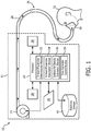
- FIG. 1 illustrates a system 10 configured for compensating for variations in air density in a pressure support device 11, in accordance with one or more embodiments.
- a pressurized flow of breathable gas is delivered to the airway of a subject 12 in accordance with a therapy regimen.
- the therapy regimen may be designed to treat a respiratory condition, such as Obesity Hypoventilation Syndrome, Obstructive Sleep Apnea, and/or other pulmonary or respiratory disorders.
- a flow rate of the pressurized flow of breathable gas delivered to the airway of subject 12 is adjusted based on an estimated ambient air density of an ambient environment of pressure support device 11.
- the estimated ambient air density is determined based on one or more measured and/or assumed parameters associated with an ambient environment of pressure support device 11.
- system 10 includes one or more of a flow generator 14, electronic storage 16, a user interface 18, one or more sensors 20, a processor 24, and/or other components.
- flow generator 14 is configured to generate a pressurized flow of breathable gas for delivery to the airway of subject 12.
- the flow generator 14 may control one or more parameters of the pressurized flow of breathable gas (e.g., flow, pressure, volume, humidity, temperature, gas composition, etc.) for therapeutic purposes, or for other purposes.
- the one or more parameters may be controlled in accordance with a therapy regimen.
- the therapy regimen may be configured to sustain and/or otherwise improve the quality of life in subject 12.
- flow generator 14 may be configured to control the pressure of the pressurized flow of breathable gas in order to treat respiratory insufficiency or obstructed airway syndrome.
- the flow generator 14 may include a positive flow generator configured to provide a positive airway pressure therapy to subject 12. Such a device is described, for example, in U.S. Patent No. 6,105,575 .
- the pressurized flow of breathable gas is delivered to the airway of subject 12 via a subject interface 26.
- Subject interface 26 is configured to communicate the pressurized flow of breathable gas generated by flow generator 14 to the airway of subject 12.
- subject interface 26 includes a conduit 28 and an interface appliance 30.
- Conduit 28 conveys the pressurized flow of breathable gas to interface appliance 30, and interface appliance 30 delivers the pressurized flow of breathable gas to the airway of subject 12.
- Some examples of interface appliance 30 may include, for example, an endotracheal tube, a nasal cannula, a nasal mask, a nasal/oral mask, a full face mask, a total face mask, or other interface appliances configured to communicate a flow of gas with an airway of a subject.
- the present disclosure is not limited to these examples, and contemplates delivery of the pressurized flow of breathable gas to subject 12 using any subject interface.
- FIG. 1 illustrates the configuration of system 10 with subject interface 26 as being a single-limb, passive system, this is not intended to be limiting. It will be appreciated that the scope of this disclosure includes embodiments in which the subject interface 26 is formed as a two-limbed system including a second conduit configured to receive exhalation from interface appliance 30.
- the second conduit may exhaust such fluid to atmosphere, may convey such fluid to a filter, and/or convey such fluid to other components including a component within system 10.
- electronic storage 16 comprises electronic storage media that electronically stores information.
- the electronic storage media of electronic storage 16 may include one or both of system storage that is provided integrally (i.e., substantially non-removable) with system 10 and/or removable storage that is removably connectable to system 10 via, for example, a port (e.g., a USB port, a firewire port, etc.) or a drive (e.g., a disk drive, etc.).
- a port e.g., a USB port, a firewire port, etc.
- a drive e.g., a disk drive, etc.
- Electronic storage 16 may include one or more of optically readable storage media (e.g., optical disks, etc.), magnetically readable storage media (e.g., magnetic tape, magnetic hard drive, floppy drive, etc.), electrical charge-based storage media (e.g., EEPROM, RAM, etc.), solid-state storage media (e.g., flash drive, etc.), and/or other electronically readable storage media.
- Electronic storage 16 may store software algorithms, look-up tables, information determined by processor 24, information received via user interface 18, and/or other information that enables system 10 to function properly.
- Electronic storage 16 may be (in whole or in part) a separate component within system 10, or electronic storage 16 may be provided (in whole or in part) integrally with one or more other components of system 10 (e.g., flow generator 14, user interface 18, processor 24, and/or other components of system 10).
- User interface 18 is configured to provide an interface between system 10 and one or more users (e.g., subject 12, a caregiver, a researcher, a therapy decision-maker, and/or other users) through which the users may provide information to and receive information from system 10.
- users e.g., subject 12, a caregiver, a researcher, a therapy decision-maker, and/or other users
- This enables data, cues, results, and/or instructions and any other communicable items, collectively referred to as "information,” to be communicated between the users and one or more of flow generator 14, electronic storage 16, processor 24, and/or other components of system 10.
- Examples of interface devices suitable for inclusion in user interface 18 include a keypad, buttons, switches, a keyboard, knobs, levers, a display screen, a touch screen, speakers, a microphone, an indicator light, an audible alarm, a printer, a tactile feedback device, and/or other interface devices.
- user interface 18 includes a plurality of separate interfaces.
- user interface 18 includes at least one interface that is provided integrally with flow generator 14.
- User interface 18 may be configured to receive input from subject 12 to modify tunable parameters of system 10.
- user interface 18 may be configured to receive input from subject 12 to modify or select sensitivity or response time of the respiratory state detection (e.g., the threshold level for breathing state transition detection may be adjusted for either an increase or a decrease in sensitivity with a graduated knob or a digital interface displaying a number from 1 to 10).
- the threshold level for breathing state transition detection may be adjusted for either an increase or a decrease in sensitivity with a graduated knob or a digital interface displaying a number from 1 to 10).
- user interface 18 may be integrated with a removable storage interface provided by electronic storage 16.
- information may be loaded into system 10 from removable storage (e.g., a smart card, a flash drive, a removable disk, etc.) that enables the user(s) to customize the implementation of system 10.
- removable storage e.g., a smart card, a flash drive, a removable disk, etc.
- Other exemplary input devices and techniques adapted for use with system 10 as user interface 18 include, but are not limited to, an RS-232 port, RF link, an IR link, modem (telephone, cable or other).
- any technique for communicating information with system 10 is contemplated by the present disclosure as user interface 18.
- sensors 20 are configured to provide one or more output signals conveying information relating to one or more parameters associated with an ambient environment of pressure support device 11.
- the ambient environment includes the atmosphere surrounding pressure support device 11.
- parameters associated with the ambient environment of pressure support device 11 include one or more of an ambient barometric air pressure, an ambient air temperature, ambient air humidity, and/or other parameters.
- the location depicted in FIG. 1 of sensors 20 is not intended to be limiting as individual sensors 20 may be disposed elsewhere in system 10.
- one or more sensors 20 may be disposed in or near an intake of pressure generator 14.
- one or more sensors 20 may be disposed proximate to a vent (not depicted in FIG. 1 ) that communicates air from immediately outside of an enclosure (not depicted in FIG.
- one or more sensors 20 may be configured to probe environmental conditions within an enclosure (not depicted in FIG. 1 ) of pressure support device 11, which may be used to determine or estimate one or more parameters associated with an ambient environment of pressure support device 11.
- ambient barometric air pressure describes the force per unit area exerted on a surface by the weight of air above that surface in the atmosphere of Earth.
- Ambient barometric air pressure may be referred to as "absolute pressure.”
- Ambient barometric air pressure differs from differential pressure in that differential pressure describes the difference between two or more pressures.
- Individual ones of sensors 20 may include a piezoresistive-strain-gauge-based pressure sensor, a capacitance-based pressure sensor, a resonance-based pressure sensor, and/or other sensors configured to provide output signals conveying information relating to ambient barometric air pressure.
- An ambient air temperature is a measure of the warmth or coldness of the air surrounding pressure support device 11.
- individual ones of sensors 20 may include a thermometer, a thermocouple, and/or other sensors configured to provide output signals conveying information relating to ambient air temperature.
- Ambient air humidity describes the amount of water vapor in the air.
- Ambient air humidity may be expressed as absolute humidity, relative humidity, and/or specific humidity.
- Absolute humidity is defined in terms of the water content of air, and can be expressed as the mass of water vapor per unit volume of air.
- Relative humidity is the ratio of the partial pressure of water vapor in the air to the saturated vapor pressure of water under the same conditions (e.g., same pressure and temperature), and is typically expressed as a percentage.
- Specific humidity is the ratio of water vapor to dry air in a particular mass of air, and is expressed as a ratio of mass of water vapor per mass of dry air.
- individual ones of sensors 20 may include a psychrometer, a hygrometer, an infrared-based humidity sensor, and/or other sensors configured to provide output signals conveying information relating to ambient air humidity.
- sensors 20 are illustrated as two separate sensors disposed in pressure support device 11, this is not intended to be limiting.
- the sensors 20 may include one or more sensors disposed in single location or a plurality of locations, such as for example, adjacent to flow generator 14, adjacent to conduit 28, adjacent to interface appliance 30, and/or other locations.
- sensors 20 may include a sensor that is separate and distinct from pressure support device 11.
- one or more of sensors 20 may be placed outside of system 10.
- the output signals generated by the externally located sensors 20 can be relayed to processor 24 by wired and/or wireless configuration.
- An independent user interface may be included with the externally located sensors 20 that receives the output signals generated by sensors 20, processes the output signals implementing some or all of the techniques described herein, and/or displaying at least some of the determined information.
- Processor 24 is configured to provide information processing capabilities in system 10.
- processor 24 may include one or more of a digital processor, an analog processor, a digital circuit designed to process information, an analog circuit designed to process information, a state machine, and/or other mechanisms for electronically processing information.
- processor 24 is shown in FIG. 1 as a single entity, this is for illustrative purposes only.
- processor 24 may include a plurality of processing units. These processing units may be physically located within the same device (e.g., flow generator 14), or processor 24 may represent processing functionality of a plurality of devices operating in coordination.
- processor 24 may be configured to execute one or more computer program modules.
- the one or more computer program modules may include one or more of an ambient parameter determination module 32, an ambient parameter assumption module 34, an ambient air density estimation module 36, a flow generator control module 38, and/or other modules.
- Processor 24 may be configured to execute modules 32, 34, 36, and/or 38 by software; hardware; firmware; some combination of software, hardware, and/or firmware; and/or other mechanisms for configuring processing capabilities on processor 24.
- modules 32, 34, 36, and 38 are illustrated in FIG. 1 as being co-located within a single processing unit, in embodiments in which processor 24 includes multiple processing units, one or more of modules 32, 34, 36, and/or 38 may be located remotely from the other modules.
- the description of the functionality provided by the different modules 32, 34, 36, and/or 38 described below is for illustrative purposes, and is not intended to be limiting, as any of modules 32, 34, 36, and/or 38 may provide more or less functionality than is described.
- processor 24 may be configured to execute one or more additional modules that may perform some or all of the functionality attributed below to one of modules 32, 34, 36, and/or 38.
- ambient parameter determination module 32 is configured to determine one or more parameters associated with the ambient environment of pressure support device 11 based on one or more output signals provided by sensors 20.
- the one or more parameters associated with the ambient environment of pressure support device 11 include one or more of an ambient barometric air pressure, an ambient air temperature, ambient air humidity, and/or other parameters.
- a given parameter can be determined using a look-up table including parameter values corresponding to information conveyed by an output signal of sensors 20.
- a given parameter may be determined by calculating the given parameter, in accordance with some embodiments.
- ambient parameter assumption module 34 is configured to determine one or more assumed parameters associated with the ambient environment of pressure support device 11 based on typical sleeping conditions of subject 12.
- the one or more assumed parameters include one or more of an assumed air temperature, an assumed air humidity, and/or other assumed parameters.
- Typical sleeping conditions describe normal ambient air temperatures and/or normal ambient air humidities in the environment in which subject 12 sleeps.
- typical sleeping conditions include an ambient air temperature of 70 °F and/or an ambient air humidity of 50% (relative humidity).
- One or more assumed parameters can be entered via user interface 18, in some embodiments.
- One or more assumed parameters may be determined when the corresponding parameter(s) cannot be determined by ambient parameter determination module 32.
- ambient air density estimation module 36 is configured to estimate an ambient air density of the ambient environment of pressure support device 11 based on one or more parameters determined by ambient parameter determination module 32 and/or one or more assumed parameters determined by ambient parameter assumption module 34.
- the ambient air density can be determined using a look-up table including air density values corresponding to one or more parameters determined by ambient parameter determination module 32 and/or one or more assumed parameters determined by ambient parameter assumption module 34.
- the ambient air density may be determined by calculating the ambient air density, in accordance with some embodiments.
- flow generator control module 38 is configured to control flow generator 14 to produce and deliver a desired therapy via the delivered breathable air. This may include controlling flow generator 14 to adjust a flow rate of the pressurized flow of breathable gas. In some embodiments, adjustments to the flow rate are based on the estimated ambient air density of the ambient environment of pressure support device, as determined by ambient air density estimation module 36. In some embodiments, flow generator control module 38 may be configured to calculate a target shaft rotational speed W of flow generator 14 that will result in the desired pressure of the pressurized flow of breathable gas delivered to the airway of subject 12.
- Flow generator control module 38 may control flow generator 14 to adjust W such that a pressurized flow of breathable gas at P set is delivered to the airway of subject 12. Calculations for W can be updated as often as necessary so as to track changes in the ambient environmental conditions in order to meet performance requirements.
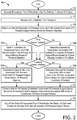
- FIG. 2 is a flow chart illustrating a method 40 for compensating for variations in air density in a pressure support device, in accordance with one or more examples.
- the operations of method 40 presented below are intended to be illustrative. In some embodiments, method 40 is accomplished with one or more additional operations not described, and/or without one or more of the operations discussed. Additionally, the order in which the operations of method 40 are illustrated in FIG. 2 and described below is not intended to be limiting.
- method 40 is implemented in one or more processing devices (e.g., a digital processor, an analog processor, a digital circuit designed to process information, an analog circuit designed to process information, a state machine, and/or other mechanisms for electronically processing information).
- the one or more processing devices may include one or more devices executing some or all of the operations of method 40 in response to instructions stored electronically on an electronic storage medium.
- the one or more processing devices may include one or more devices configured through hardware, firmware, and/or software to be specifically designed for execution of one or more of the operations of method 40.
- a pressurized flow of breathable gas is generated for delivery to the airway of a subject. Operation 42 may be performed by flow generator 14, in accordance with one or more embodiments.
- one or more output signals are received from one or more sensors.
- Individual output signals convey information relating to one or more parameters associated with an ambient environment of a pressure support device (e.g., pressure support device 11).
- the one or more parameters associated with the ambient environment of the pressure support device include one or more of an ambient barometric air pressure, an ambient air temperature, ambient air humidity, and/or other parameters.
- the one or more sensors may include sensors 20. Operation 44 may be performed by processor 24.
- an ambient barometric air pressure associated with the ambient environment of the pressure support device is determined based on the one or more output signals received at operation 44.
- Operation 46 is performed by an ambient parameter determination module that is the same as or similar to ambient parameter determination module 32, in accordance with one or more embodiments.
- an ambient air temperature associated with the ambient environment of the pressure support device is determined based on the one or more output signals received at operation 44.
- Operation 48a is performed by an ambient parameter determination module that is the same as or similar to ambient parameter determination module 32, in accordance with one or more embodiments.
- an assumed air temperature associated with the ambient environment of the pressure support device is determined based on typical sleeping conditions of the subject. Operation 48b is performed by an ambient parameter assumption module that is the same as or similar to ambient parameter assumption module 34, in accordance with one or more embodiments.
- an ambient air humidity associated with the ambient environment of the pressure support device is determined based on the one or more output signals received at operation 44.
- Operation 50a is performed by an ambient parameter determination module that is the same as or similar to ambient parameter determination module 32, in accordance with one or more embodiments.
- an assumed air humidity associated with the ambient environment of the pressure support device is determined based on typical sleeping conditions of the subject. Operation 50b is performed by an ambient parameter assumption module that is the same as or similar to ambient parameter assumption module 34, in accordance with one or more embodiments.
- an ambient air density of the ambient environment of the pressure support device is estimated based on individual parameters (e.g., ambient barometric air pressure, ambient air temperature, ambient air humidity, and/or other parameters) and/or assumed parameters (e.g., assumed air temperature, assumed air humidity, and/or other assumed parameters) associated with the ambient environment of the pressure support device.
- Operation 52 is performed by an ambient air density estimation module that is the same as or similar to ambient air density estimation module 36, in accordance with one or more embodiments.
- a flow rate of the pressurized flow of breathable gas is adjusted based on the estimated ambient air density of the ambient environment of the pressure support device. Operation 54 is performed by a flow generator control module that is the same as or similar to flow generator control module 38 in conjunction with flow generator 14, in accordance with one or more embodiments.
- any reference signs placed between parentheses shall not be construed as limiting the claim.
- the word “comprising” or “including” does not exclude the presence of elements or steps other than those listed in a claim.
- several of these means may be embodied by one and the same item of hardware.
- the word “a” or “an” preceding an element does not exclude the presence of a plurality of such elements.
- any device claim enumerating several means several of these means may be embodied by one and the same item of hardware.
- the mere fact that certain elements are recited in mutually different dependent claims does not indicate that these elements cannot be used in combination.
Landscapes
- Health & Medical Sciences (AREA)
- Emergency Medicine (AREA)
- Pulmonology (AREA)
- Engineering & Computer Science (AREA)
- Anesthesiology (AREA)
- Biomedical Technology (AREA)
- Heart & Thoracic Surgery (AREA)
- Hematology (AREA)
- Life Sciences & Earth Sciences (AREA)
- Animal Behavior & Ethology (AREA)
- General Health & Medical Sciences (AREA)
- Public Health (AREA)
- Veterinary Medicine (AREA)
- Measurement Of The Respiration, Hearing Ability, Form, And Blood Characteristics Of Living Organisms (AREA)
- Air Conditioning Control Device (AREA)
Applications Claiming Priority (2)
| Application Number | Priority Date | Filing Date | Title |
|---|---|---|---|
| US201261604545P | 2012-02-29 | 2012-02-29 | |
| PCT/IB2013/051510 WO2013128365A1 (en) | 2012-02-29 | 2013-02-25 | Compensating for variations in air density in a pressure support device |
Publications (2)
| Publication Number | Publication Date |
|---|---|
| EP2819728A1 EP2819728A1 (en) | 2015-01-07 |
| EP2819728B1 true EP2819728B1 (en) | 2019-07-31 |
Family
ID=48184246
Family Applications (1)
| Application Number | Title | Priority Date | Filing Date |
|---|---|---|---|
| EP13718628.4A Active EP2819728B1 (en) | 2012-02-29 | 2013-02-25 | Compensating for variations in air density in a pressure support device |
Country Status (6)
Families Citing this family (17)
| Publication number | Priority date | Publication date | Assignee | Title |
|---|---|---|---|---|
| AU2013244090B2 (en) | 2012-04-05 | 2018-04-05 | Fisher & Paykel Healthcare Limited | Respiratory assistance apparatus |
| CN107261270B (zh) * | 2012-06-29 | 2021-03-02 | 瑞思迈私人有限公司 | 用于呼吸装置的压力传感器评估 |
| US9541098B2 (en) | 2013-06-28 | 2017-01-10 | Vyaire Medical Capital Llc | Low-noise blower |
| US9746359B2 (en) | 2013-06-28 | 2017-08-29 | Vyaire Medical Capital Llc | Flow sensor |
| US9707369B2 (en) * | 2013-06-28 | 2017-07-18 | Vyaire Medical Capital Llc | Modular flow cassette |
| US9795757B2 (en) | 2013-06-28 | 2017-10-24 | Vyaire Medical Capital Llc | Fluid inlet adapter |
| US9962514B2 (en) | 2013-06-28 | 2018-05-08 | Vyaire Medical Capital Llc | Ventilator flow valve |
| CN103462790B (zh) * | 2013-09-27 | 2015-08-05 | 王岩泽 | 交变气压理疗室 |
| CN115554543A (zh) | 2014-05-27 | 2023-01-03 | 费雪派克医疗保健有限公司 | 用于医疗装置的气体混合和测量 |
| CA2982223C (en) * | 2015-04-13 | 2023-08-22 | Medela Holding Ag | Pressure system with absolute pressure sensor |
| CN107847699A (zh) * | 2015-06-30 | 2018-03-27 | 皇家飞利浦有限公司 | 用于可变阻力气道正压设备管路补偿的气压传感器 |
| EP3383470B8 (en) | 2015-12-02 | 2022-05-25 | Fisher&Paykel Healthcare Limited | Flow path sensing for flow therapy apparatus |
| US10888721B2 (en) * | 2016-07-28 | 2021-01-12 | Design West Technologies, Inc. | Breath responsive powered air purifying respirator |
| CN109045429B (zh) * | 2018-08-23 | 2021-03-26 | 深圳融昕医疗科技有限公司 | 孕妇通气控制系统 |
| AU2020323298A1 (en) * | 2019-07-30 | 2022-02-03 | ResMed Pty Ltd | Methods and apparatus for respiratory therapy |
| CN112870502A (zh) * | 2019-11-29 | 2021-06-01 | 深圳市大雅医疗技术有限公司 | 呼吸机控制方法、装置、呼吸机和存储介质 |
| CN115585543A (zh) * | 2022-10-12 | 2023-01-10 | 青岛海尔空调器有限总公司 | 温度处理方法、装置、设备和计算机存储介质 |
Family Cites Families (12)
| Publication number | Priority date | Publication date | Assignee | Title |
|---|---|---|---|---|
| US6105575A (en) | 1994-06-03 | 2000-08-22 | Respironics, Inc. | Method and apparatus for providing positive airway pressure to a patient |
| US6167107A (en) * | 1999-07-16 | 2000-12-26 | Particle Measuring Systems, Inc. | Air pump for particle sensing using regenerative fan, and associated methods |
| DE10161057A1 (de) | 2001-12-12 | 2003-07-10 | Heptec Gmbh | Verfahren zur Steuerung des Differenzdrucks in einem CPAP-Gerät sowie CPAP-Gerät |
| US8561611B2 (en) | 2005-06-21 | 2013-10-22 | Ric Investments, Llc | Respiratory device measurement system |
| US20090107500A1 (en) | 2007-10-25 | 2009-04-30 | Sequal Technologies, Inc. | Portable Oxygen Concentrator System and Method Including Concentrated Oxygen Flow Delivery |
| CN101468219B (zh) * | 2007-12-28 | 2012-10-31 | 北京谊安医疗系统股份有限公司 | 气路系统及其操作方法以及采用该系统的呼吸机和麻醉机 |
| CN113425974B (zh) * | 2008-03-06 | 2024-12-10 | 瑞思迈私人有限公司 | 呼吸气体的湿化 |
| US9802022B2 (en) * | 2008-03-06 | 2017-10-31 | Resmed Limited | Humidification of respiratory gases |
| GB0919818D0 (en) * | 2009-09-16 | 2009-12-30 | Airbus Operations Ltd | Adaptable oxygen regulator system and method with an electronic control device |
| JP5818214B2 (ja) * | 2009-11-11 | 2015-11-18 | ザ ボード オブ トラスティーズ オブ ザ レランド スタンフォード ジュニア ユニバーシティー | 人工呼吸器 |
| EP2509668B1 (en) | 2009-12-07 | 2016-05-18 | Koninklijke Philips N.V. | System for providing support therapy while determining concentrations of a molecular gaseous expired by a subject receiving pressure support therapy |
| DE102010031754B4 (de) * | 2010-07-21 | 2012-08-23 | Dräger Safety AG & Co. KGaA | Atemschutzgerät mit Kompensation des Umgebungsdruckes |
-
2013
- 2013-02-25 CN CN201380011402.5A patent/CN104144722B/zh active Active
- 2013-02-25 WO PCT/IB2013/051510 patent/WO2013128365A1/en active Application Filing
- 2013-02-25 EP EP13718628.4A patent/EP2819728B1/en active Active
- 2013-02-25 US US14/379,671 patent/US10226590B2/en active Active
- 2013-02-25 JP JP2014559332A patent/JP6342816B2/ja active Active
- 2013-02-25 RU RU2014139003A patent/RU2014139003A/ru not_active Application Discontinuation
Non-Patent Citations (1)
| Title |
|---|
| None * |
Also Published As
| Publication number | Publication date |
|---|---|
| CN104144722B (zh) | 2017-04-19 |
| EP2819728A1 (en) | 2015-01-07 |
| US10226590B2 (en) | 2019-03-12 |
| US20150020807A1 (en) | 2015-01-22 |
| JP6342816B2 (ja) | 2018-06-13 |
| CN104144722A (zh) | 2014-11-12 |
| RU2014139003A (ru) | 2016-04-20 |
| JP2015508694A (ja) | 2015-03-23 |
| WO2013128365A1 (en) | 2013-09-06 |
Similar Documents
| Publication | Publication Date | Title |
|---|---|---|
| EP2819728B1 (en) | Compensating for variations in air density in a pressure support device | |
| US20250152901A1 (en) | Humidification breathing apparatus control | |
| EP3193997B1 (en) | System and method for adjusting parameters during pressure support therapy | |
| AU2008360394B2 (en) | System and method for determining humidity in a respiratory treatment system | |
| EP2817058B1 (en) | Rainout protection for respiratory therapy including humidification | |
| US8353291B2 (en) | Systems and methods for compensating for pressure drop in a breathing assistance system | |
| US10279140B2 (en) | Humidity control liquid maximization pressure support device | |
| EP2509668B1 (en) | System for providing support therapy while determining concentrations of a molecular gaseous expired by a subject receiving pressure support therapy | |
| AU2011333436B2 (en) | Obesity hypoventilation syndrome treatment system and method | |
| US10806878B2 (en) | System and method for determining a target subject interface temperature based on a baseline temperature | |
| EP2515979A1 (en) | Automatic identification of a patient interface device in a pressure support system | |
| KR20210153061A (ko) | 버블 cpap 요법을 제공하는 호흡 장치 | |
| EP2991715B1 (en) | Critical care ventilator with mouth piece ventilation | |
| US10384025B2 (en) | System and method for limiting flow and/or pressure compensation during limited flow respiratory therapy | |
| EP2885038A1 (en) | Patient interface assembly disconnect detection | |
| US10500357B2 (en) | Methods and systems to manage central sleep apnea by controlling accumulated retrograde volume | |
| US10881821B2 (en) | Mechanical ventilation based on alveolar ventilation |
Legal Events
| Date | Code | Title | Description |
|---|---|---|---|
| PUAI | Public reference made under article 153(3) epc to a published international application that has entered the european phase |
Free format text: ORIGINAL CODE: 0009012 |
|
| 17P | Request for examination filed |
Effective date: 20140929 |
|
| AK | Designated contracting states |
Kind code of ref document: A1 Designated state(s): AL AT BE BG CH CY CZ DE DK EE ES FI FR GB GR HR HU IE IS IT LI LT LU LV MC MK MT NL NO PL PT RO RS SE SI SK SM TR |
|
| AX | Request for extension of the european patent |
Extension state: BA ME |
|
| DAX | Request for extension of the european patent (deleted) | ||
| STAA | Information on the status of an ep patent application or granted ep patent |
Free format text: STATUS: EXAMINATION IS IN PROGRESS |
|
| 17Q | First examination report despatched |
Effective date: 20170213 |
|
| REG | Reference to a national code |
Ref country code: DE Ref legal event code: R079 Ref document number: 602013058460 Country of ref document: DE Free format text: PREVIOUS MAIN CLASS: A61M0016000000 Ipc: A61M0016060000 |
|
| GRAP | Despatch of communication of intention to grant a patent |
Free format text: ORIGINAL CODE: EPIDOSNIGR1 |
|
| STAA | Information on the status of an ep patent application or granted ep patent |
Free format text: STATUS: GRANT OF PATENT IS INTENDED |
|
| RIC1 | Information provided on ipc code assigned before grant |
Ipc: A61M 16/06 20060101AFI20190114BHEP Ipc: A61M 16/08 20060101ALI20190114BHEP Ipc: A61M 16/00 20060101ALI20190114BHEP Ipc: A61M 16/16 20060101ALI20190114BHEP |
|
| INTG | Intention to grant announced |
Effective date: 20190208 |
|
| RIN1 | Information on inventor provided before grant (corrected) |
Inventor name: KIMMEL, STEVEN ADAM |
|
| GRAS | Grant fee paid |
Free format text: ORIGINAL CODE: EPIDOSNIGR3 |
|
| GRAA | (expected) grant |
Free format text: ORIGINAL CODE: 0009210 |
|
| STAA | Information on the status of an ep patent application or granted ep patent |
Free format text: STATUS: THE PATENT HAS BEEN GRANTED |
|
| AK | Designated contracting states |
Kind code of ref document: B1 Designated state(s): AL AT BE BG CH CY CZ DE DK EE ES FI FR GB GR HR HU IE IS IT LI LT LU LV MC MK MT NL NO PL PT RO RS SE SI SK SM TR |
|
| REG | Reference to a national code |
Ref country code: CH Ref legal event code: EP Ref country code: GB Ref legal event code: FG4D |
|
| REG | Reference to a national code |
Ref country code: DE Ref legal event code: R096 Ref document number: 602013058460 Country of ref document: DE |
|
| REG | Reference to a national code |
Ref country code: AT Ref legal event code: REF Ref document number: 1160282 Country of ref document: AT Kind code of ref document: T Effective date: 20190815 |
|
| REG | Reference to a national code |
Ref country code: IE Ref legal event code: FG4D |
|
| REG | Reference to a national code |
Ref country code: NL Ref legal event code: MP Effective date: 20190731 |
|
| REG | Reference to a national code |
Ref country code: LT Ref legal event code: MG4D |
|
| REG | Reference to a national code |
Ref country code: AT Ref legal event code: MK05 Ref document number: 1160282 Country of ref document: AT Kind code of ref document: T Effective date: 20190731 |
|
| PG25 | Lapsed in a contracting state [announced via postgrant information from national office to epo] |
Ref country code: FI Free format text: LAPSE BECAUSE OF FAILURE TO SUBMIT A TRANSLATION OF THE DESCRIPTION OR TO PAY THE FEE WITHIN THE PRESCRIBED TIME-LIMIT Effective date: 20190731 Ref country code: NO Free format text: LAPSE BECAUSE OF FAILURE TO SUBMIT A TRANSLATION OF THE DESCRIPTION OR TO PAY THE FEE WITHIN THE PRESCRIBED TIME-LIMIT Effective date: 20191031 Ref country code: BG Free format text: LAPSE BECAUSE OF FAILURE TO SUBMIT A TRANSLATION OF THE DESCRIPTION OR TO PAY THE FEE WITHIN THE PRESCRIBED TIME-LIMIT Effective date: 20191031 Ref country code: SE Free format text: LAPSE BECAUSE OF FAILURE TO SUBMIT A TRANSLATION OF THE DESCRIPTION OR TO PAY THE FEE WITHIN THE PRESCRIBED TIME-LIMIT Effective date: 20190731 Ref country code: AT Free format text: LAPSE BECAUSE OF FAILURE TO SUBMIT A TRANSLATION OF THE DESCRIPTION OR TO PAY THE FEE WITHIN THE PRESCRIBED TIME-LIMIT Effective date: 20190731 Ref country code: HR Free format text: LAPSE BECAUSE OF FAILURE TO SUBMIT A TRANSLATION OF THE DESCRIPTION OR TO PAY THE FEE WITHIN THE PRESCRIBED TIME-LIMIT Effective date: 20190731 Ref country code: LT Free format text: LAPSE BECAUSE OF FAILURE TO SUBMIT A TRANSLATION OF THE DESCRIPTION OR TO PAY THE FEE WITHIN THE PRESCRIBED TIME-LIMIT Effective date: 20190731 Ref country code: PT Free format text: LAPSE BECAUSE OF FAILURE TO SUBMIT A TRANSLATION OF THE DESCRIPTION OR TO PAY THE FEE WITHIN THE PRESCRIBED TIME-LIMIT Effective date: 20191202 Ref country code: NL Free format text: LAPSE BECAUSE OF FAILURE TO SUBMIT A TRANSLATION OF THE DESCRIPTION OR TO PAY THE FEE WITHIN THE PRESCRIBED TIME-LIMIT Effective date: 20190731 |
|
| PG25 | Lapsed in a contracting state [announced via postgrant information from national office to epo] |
Ref country code: IS Free format text: LAPSE BECAUSE OF FAILURE TO SUBMIT A TRANSLATION OF THE DESCRIPTION OR TO PAY THE FEE WITHIN THE PRESCRIBED TIME-LIMIT Effective date: 20191130 Ref country code: AL Free format text: LAPSE BECAUSE OF FAILURE TO SUBMIT A TRANSLATION OF THE DESCRIPTION OR TO PAY THE FEE WITHIN THE PRESCRIBED TIME-LIMIT Effective date: 20190731 Ref country code: LV Free format text: LAPSE BECAUSE OF FAILURE TO SUBMIT A TRANSLATION OF THE DESCRIPTION OR TO PAY THE FEE WITHIN THE PRESCRIBED TIME-LIMIT Effective date: 20190731 Ref country code: ES Free format text: LAPSE BECAUSE OF FAILURE TO SUBMIT A TRANSLATION OF THE DESCRIPTION OR TO PAY THE FEE WITHIN THE PRESCRIBED TIME-LIMIT Effective date: 20190731 Ref country code: GR Free format text: LAPSE BECAUSE OF FAILURE TO SUBMIT A TRANSLATION OF THE DESCRIPTION OR TO PAY THE FEE WITHIN THE PRESCRIBED TIME-LIMIT Effective date: 20191101 Ref country code: RS Free format text: LAPSE BECAUSE OF FAILURE TO SUBMIT A TRANSLATION OF THE DESCRIPTION OR TO PAY THE FEE WITHIN THE PRESCRIBED TIME-LIMIT Effective date: 20190731 |
|
| RAP2 | Party data changed (patent owner data changed or rights of a patent transferred) |
Owner name: KONINKLIJKE PHILIPS N.V. |
|
| PG25 | Lapsed in a contracting state [announced via postgrant information from national office to epo] |
Ref country code: TR Free format text: LAPSE BECAUSE OF FAILURE TO SUBMIT A TRANSLATION OF THE DESCRIPTION OR TO PAY THE FEE WITHIN THE PRESCRIBED TIME-LIMIT Effective date: 20190731 |
|
| PG25 | Lapsed in a contracting state [announced via postgrant information from national office to epo] |
Ref country code: RO Free format text: LAPSE BECAUSE OF FAILURE TO SUBMIT A TRANSLATION OF THE DESCRIPTION OR TO PAY THE FEE WITHIN THE PRESCRIBED TIME-LIMIT Effective date: 20190731 Ref country code: PL Free format text: LAPSE BECAUSE OF FAILURE TO SUBMIT A TRANSLATION OF THE DESCRIPTION OR TO PAY THE FEE WITHIN THE PRESCRIBED TIME-LIMIT Effective date: 20190731 Ref country code: DK Free format text: LAPSE BECAUSE OF FAILURE TO SUBMIT A TRANSLATION OF THE DESCRIPTION OR TO PAY THE FEE WITHIN THE PRESCRIBED TIME-LIMIT Effective date: 20190731 Ref country code: EE Free format text: LAPSE BECAUSE OF FAILURE TO SUBMIT A TRANSLATION OF THE DESCRIPTION OR TO PAY THE FEE WITHIN THE PRESCRIBED TIME-LIMIT Effective date: 20190731 Ref country code: IT Free format text: LAPSE BECAUSE OF FAILURE TO SUBMIT A TRANSLATION OF THE DESCRIPTION OR TO PAY THE FEE WITHIN THE PRESCRIBED TIME-LIMIT Effective date: 20190731 |
|
| PG25 | Lapsed in a contracting state [announced via postgrant information from national office to epo] |
Ref country code: SK Free format text: LAPSE BECAUSE OF FAILURE TO SUBMIT A TRANSLATION OF THE DESCRIPTION OR TO PAY THE FEE WITHIN THE PRESCRIBED TIME-LIMIT Effective date: 20190731 Ref country code: SM Free format text: LAPSE BECAUSE OF FAILURE TO SUBMIT A TRANSLATION OF THE DESCRIPTION OR TO PAY THE FEE WITHIN THE PRESCRIBED TIME-LIMIT Effective date: 20190731 Ref country code: CZ Free format text: LAPSE BECAUSE OF FAILURE TO SUBMIT A TRANSLATION OF THE DESCRIPTION OR TO PAY THE FEE WITHIN THE PRESCRIBED TIME-LIMIT Effective date: 20190731 Ref country code: IS Free format text: LAPSE BECAUSE OF FAILURE TO SUBMIT A TRANSLATION OF THE DESCRIPTION OR TO PAY THE FEE WITHIN THE PRESCRIBED TIME-LIMIT Effective date: 20200224 |
|
| REG | Reference to a national code |
Ref country code: DE Ref legal event code: R097 Ref document number: 602013058460 Country of ref document: DE |
|
| PLBE | No opposition filed within time limit |
Free format text: ORIGINAL CODE: 0009261 |
|
| STAA | Information on the status of an ep patent application or granted ep patent |
Free format text: STATUS: NO OPPOSITION FILED WITHIN TIME LIMIT |
|
| PG2D | Information on lapse in contracting state deleted |
Ref country code: IS |
|
| PG25 | Lapsed in a contracting state [announced via postgrant information from national office to epo] |
Ref country code: IS Free format text: LAPSE BECAUSE OF FAILURE TO SUBMIT A TRANSLATION OF THE DESCRIPTION OR TO PAY THE FEE WITHIN THE PRESCRIBED TIME-LIMIT Effective date: 20191030 |
|
| 26N | No opposition filed |
Effective date: 20200603 |
|
| PG25 | Lapsed in a contracting state [announced via postgrant information from national office to epo] |
Ref country code: SI Free format text: LAPSE BECAUSE OF FAILURE TO SUBMIT A TRANSLATION OF THE DESCRIPTION OR TO PAY THE FEE WITHIN THE PRESCRIBED TIME-LIMIT Effective date: 20190731 |
|
| REG | Reference to a national code |
Ref country code: CH Ref legal event code: PL |
|
| GBPC | Gb: european patent ceased through non-payment of renewal fee |
Effective date: 20200225 |
|
| REG | Reference to a national code |
Ref country code: BE Ref legal event code: MM Effective date: 20200229 |
|
| PG25 | Lapsed in a contracting state [announced via postgrant information from national office to epo] |
Ref country code: LU Free format text: LAPSE BECAUSE OF NON-PAYMENT OF DUE FEES Effective date: 20200225 Ref country code: MC Free format text: LAPSE BECAUSE OF FAILURE TO SUBMIT A TRANSLATION OF THE DESCRIPTION OR TO PAY THE FEE WITHIN THE PRESCRIBED TIME-LIMIT Effective date: 20190731 |
|
| PG25 | Lapsed in a contracting state [announced via postgrant information from national office to epo] |
Ref country code: CH Free format text: LAPSE BECAUSE OF NON-PAYMENT OF DUE FEES Effective date: 20200229 Ref country code: LI Free format text: LAPSE BECAUSE OF NON-PAYMENT OF DUE FEES Effective date: 20200229 |
|
| PG25 | Lapsed in a contracting state [announced via postgrant information from national office to epo] |
Ref country code: IE Free format text: LAPSE BECAUSE OF NON-PAYMENT OF DUE FEES Effective date: 20200225 Ref country code: GB Free format text: LAPSE BECAUSE OF NON-PAYMENT OF DUE FEES Effective date: 20200225 |
|
| PG25 | Lapsed in a contracting state [announced via postgrant information from national office to epo] |
Ref country code: BE Free format text: LAPSE BECAUSE OF NON-PAYMENT OF DUE FEES Effective date: 20200229 |
|
| PG25 | Lapsed in a contracting state [announced via postgrant information from national office to epo] |
Ref country code: MT Free format text: LAPSE BECAUSE OF FAILURE TO SUBMIT A TRANSLATION OF THE DESCRIPTION OR TO PAY THE FEE WITHIN THE PRESCRIBED TIME-LIMIT Effective date: 20190731 Ref country code: CY Free format text: LAPSE BECAUSE OF FAILURE TO SUBMIT A TRANSLATION OF THE DESCRIPTION OR TO PAY THE FEE WITHIN THE PRESCRIBED TIME-LIMIT Effective date: 20190731 |
|
| PG25 | Lapsed in a contracting state [announced via postgrant information from national office to epo] |
Ref country code: MK Free format text: LAPSE BECAUSE OF FAILURE TO SUBMIT A TRANSLATION OF THE DESCRIPTION OR TO PAY THE FEE WITHIN THE PRESCRIBED TIME-LIMIT Effective date: 20190731 |
|
| PGFP | Annual fee paid to national office [announced via postgrant information from national office to epo] |
Ref country code: DE Payment date: 20250226 Year of fee payment: 13 |
|
| PGFP | Annual fee paid to national office [announced via postgrant information from national office to epo] |
Ref country code: FR Payment date: 20250224 Year of fee payment: 13 |