EP2819280A1 - Sliding contact member, and dc motor and generator using said sliding contact member - Google Patents
Sliding contact member, and dc motor and generator using said sliding contact member Download PDFInfo
- Publication number
- EP2819280A1 EP2819280A1 EP13751834.6A EP13751834A EP2819280A1 EP 2819280 A1 EP2819280 A1 EP 2819280A1 EP 13751834 A EP13751834 A EP 13751834A EP 2819280 A1 EP2819280 A1 EP 2819280A1
- Authority
- EP
- European Patent Office
- Prior art keywords
- sliding contact
- contact member
- electrically conductive
- powder compact
- compact portion
- Prior art date
- Legal status (The legal status is an assumption and is not a legal conclusion. Google has not performed a legal analysis and makes no representation as to the accuracy of the status listed.)
- Granted
Links
Images






Classifications
-
- H—ELECTRICITY
- H01—ELECTRIC ELEMENTS
- H01R—ELECTRICALLY-CONDUCTIVE CONNECTIONS; STRUCTURAL ASSOCIATIONS OF A PLURALITY OF MUTUALLY-INSULATED ELECTRICAL CONNECTING ELEMENTS; COUPLING DEVICES; CURRENT COLLECTORS
- H01R39/00—Rotary current collectors, distributors or interrupters
- H01R39/02—Details for dynamo electric machines
- H01R39/18—Contacts for co-operation with commutator or slip-ring, e.g. contact brush
- H01R39/20—Contacts for co-operation with commutator or slip-ring, e.g. contact brush characterised by the material thereof
-
- H—ELECTRICITY
- H02—GENERATION; CONVERSION OR DISTRIBUTION OF ELECTRIC POWER
- H02K—DYNAMO-ELECTRIC MACHINES
- H02K13/00—Structural associations of current collectors with motors or generators, e.g. brush mounting plates or connections to windings; Disposition of current collectors in motors or generators; Arrangements for improving commutation
- H02K13/10—Arrangements of brushes or commutators specially adapted for improving commutation
-
- H—ELECTRICITY
- H02—GENERATION; CONVERSION OR DISTRIBUTION OF ELECTRIC POWER
- H02K—DYNAMO-ELECTRIC MACHINES
- H02K13/00—Structural associations of current collectors with motors or generators, e.g. brush mounting plates or connections to windings; Disposition of current collectors in motors or generators; Arrangements for improving commutation
- H02K13/006—Structural associations of commutators
Definitions
- the present invention relates to a sliding contact member, and a DC motor and a generator using said sliding contact member.
- Patent Document 1 One such conventional technique is disclosed in Patent Document 1, where the product is referred to as an "electrically conductive member".
- the electrically conductive member disclosed in Patent Document 1 establishes electrical connection by a plurality of electrically conductive members making contact with each other, in which at least one of the electrically conductive members includes an electrically conductive hard carbon-containing film at a portion to be in contact with the other member. This electrically conductive member is used as contacts of keys.
- Patent Document 1 Japanese Patent Unexamined Publication No. 2002-25346
- the electrically conductive member disclosed in Patent Document 1 is used as, for example, a brush and a commutator of drive motors or generators, the electric power flowing through the brush increases. Furthermore, the electrically conductive member is subjected to a higher sliding speed and a higher sliding contact pressure as the sliding speed of the brush increases. This increases heat generation in the brush, which causes thermal softening of the material. As a result, the brush or the counterpart thereof, i.e. the commutator, is subjected to a greater amount of wear. Another problem is that the heat generated in the brush and commutator does not sufficiently diffuse over the sliding surface, which causes a local temperature rise that softens the material.
- the present invention for solving the above-described problems is as follows.
- the sliding contact member of the present invention reduces heat generation and resulting wear by providing a powder compact portion that contains an electrically conductive diamond and an electrically conductive binder and is placed at a sliding contact portion of either or both of two sliding contact members slidably in contact with each other.
- the DC motor and the generator of the present invention use the above-described sliding contact member as a brush or a commutator. This promotes heat diffusion in the brush and commutator, and thereby prevents heat from locally rising.
- a sliding contact member of the present invention includes a powder compact portion that contains an electrically conductive diamond and is provided at least at a sliding contact portion of either or both of two sliding contact members slidably in contact with each other.
- electrically conductive diamond refers to a diamond semiconductor doped with an impurity (e.g. boron (B)).
- a compound semiconductor may be used as the "electrically conductive binder".
- Such compound semiconductors include, for example, Zn, Cd, Hg, B, Al, Ga, In, Tl, N, P, As, Sb, Bi, O, S, Se, Te, Po, and the like.
- the improvement in heat conduction improves the discharge resistance, which results in reduced electrical abrasion. Further, since inexpensive diamond particles are used for the powder compact portion, it is possible to produce the sliding contact member at low cost.
- the powder compact portion contains both the electrically conductive diamond powder and the electrically conductive binder that binds the electrically conductive diamond powder together, so the strength and the adhesiveness of the electrically conductive diamond powder can be improved. This improves the apparent strength, heat conductivity and electrical conductivity of the powder compact portion.
- a powder having a specific electrical resistance lower than the electrically conductive diamond particles is used as the electrically conductive binder, so the specific electrical resistance between the electrically conductive diamond powder is reduced, which improves the above-described apparent electrical conductivity of the powder compact portion.
- the volume ratio of the electrically conductive diamond By increasing the volume ratio of the electrically conductive diamond to 50% or more, the volume ratio of the electrically conductive diamond in the powder compact portion is improved, which improves the apparent strength of the powder compact portion. Therefore, the wear resistance and the seizing resistance can be improved.
- the specific electrical resistance of the electrically conductive diamond powder is decreased. Therefore, the apparent electrical conductivity of the powder compact portion can be improved.
- an electrically conductive diamond having a powder size of not more than 5 ⁇ m it is possible to reduce the surface roughness of the worn sliding contact surface of the powder compact portion and to reduce mechanical abrasion.
- any one of Cu, Al, Ni, Ti, Zn, Co, Au and Ag as a low-specific electrical resistance material, the specific electrical resistance of the powder other than the electrically conductive diamond can be decreased. Therefore, the apparent electrical conductivity of the powder compact portion can be improved. Furthermore, as this enables production by powder deposition, the sliding contact member can be produced at low cost.
- the heat dissipation of the powder compact portion is improved. Therefore, it is possible to prevent local temperature rise in the sliding contact surface, which can reduce wear due to heat degradation.
- the heat conductivity of the powder compact portion is improved. Therefore it is possible to prevent local temperature rise in the sliding contact surface, which can reduce wear due to heat degradation.
- the high density compact portion can be produced at low cost.
- powder deposition to produce the above-described powder compact portion the powder compact portion having higher density can be produced at even lower cost.
- the above-described sliding contact member for either or both of a brush and a commutator, DC motors and generators can be produced at low cost. Examples
- the amount of wear (specific amount of wear) of diamond will be described.
- the wear of diamond could not be measured by using basic measuring methods. Accordingly, the amount of wear of diamond was calculated from the maximum height of a surface roughness curve measured by an AFM (atomic force microscope) (see Fig. 1(A) ) and an expected area of contact with a counterpart (see Fig. 1(B) ).
- FIG. 2 is an explanatory view illustrating a first evaluation method, where a copper ball and the sliding contact member of the present invention are indicated by reference signs 1 and 2 respectively.
- the arrow in Fig. 2 indicates the rolling direction of the ball 1.
- the amount of wear was evaluated by the ball-on-disk method (300 min) as illustrated in Fig. 2 .
- (Evaluation Result) As shown in table 1, the wear resistance is drastically improved. Furthermore, the aggression to the counterpart (ball 1) is low.
- FIG. 3 is an explanatory view illustrating a second evaluation method, where a copper electrode, the sliding contact member of the present invention and a DC power source for applying electric current between them are indicated by reference signs 3, 4 and 5 respectively.
- the arrow in Fig. 3 indicates the moving direction of the electrode 3.
- the discharge resistance (the amount of wear) was evaluated by the electrical discharge machining as illustrated in Fig. 3 .
- (Evaluation Result) As shown in table 2, the wear resistance is drastically improved. Furthermore, the aggression to the counterpart (electrode 3) is low.
- FIG. 4 is an explanatory view illustrating a third evaluation method, where a copper ball, the sliding contact member of the present invention and a DC power source for providing electricity between them are indicated by reference signs 6, 7 and 8 respectively.
- the arrow in Fig. 4 indicates the rolling direction of the ball 6.
- the amount of wear was evaluated by the electrified slide test as illustrated in Fig. 4 .
- (Evaluation Result) As shown in table 3, the wear resistance is drastically improved. Furthermore, the aggression to the counterpart (ball 6) is low.
- FIG. 5 is an explanatory view illustrating a fourth evaluation method, where a copper ball and the sliding contact member of the present invention are indicated by reference signs 9 and 10 respectively.
- the arrow in Fig. 5 indicates the rolling direction of the ball 9.
- the seizing resistance was evaluated by the seizing test as illustrated in Fig. 5 .
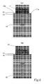
- Fig. 6 is an explanatory view illustrating a fifth evaluation method, where (A) is a schematic explanatory view of two sliding contact members each having a 10 ⁇ m thick powder compact portion, and (B) is a schematic explanatory view of two sliding contact members each having a 500 ⁇ m thick powder compact portion.
- Fig. 7 is an explanatory view illustrating a simulation result when the thickness of both powder compact portions is 10 ⁇ m
- Fig. 8 is an explanatory view illustrating a simulation result when the thickness is 500 ⁇ m.
- one sliding contact member which is indicated by reference sign 11, and the other sliding contact member, which is indicated by reference sign 12, are slidably in contact with each other. They are made of carbon and iron (copper) respectively.
- 10 ⁇ m thick powder compact portions 13, 13 are formed on both sliding contact surfaces 11a and 12a of the respective sliding contact members 11 and 12.
- 500 ⁇ m thick powder compact portions 14, 14 are formed on both sliding contact surfaces 11a and 12a of the respective sliding contact members 11 and 12.
- Fig. 9 is (A) a cross sectional view schematically illustrating the structure of an exemplary DC brush motor, and (B) a magnification of the part of (A) indicated by envelop I.
- the DC brush motor A of Fig. 9(A) includes an approximately cylindrical case 20, bearings 21, 21 that are coaxially fitted in respective opposing end faces 20a, 20a of the case 20, and a drive shaft 22 that is rotatably supported by the bearings 21, 21.
- a coil 23 and a commutator 24 are provided on the drive shaft 22, and a magnet 25 is provided on the inner wall of the case 20.
- Brushes 26 are provided on the case 20 via springs 27, which are slidable on the commutator 24.
- a DC power source is indicated by reference sign 26.
- the commutator 24 includes a powder compact portion 24a of a requisite thickness that has the above-described configuration and is formed on a sliding contact surface with the brushes 26.
- each of the brushes 26 includes a powder compact portion 26a of a requisite thickness that has the above-described configuration and is formed on a sliding contact surface with the commutator 24.
- the brushes 26 and the commutator 24 of the above-described DC motor A or those of a generator wear away by (1) mechanical abrasion and (2) electrical abrasion (loss of the material due to electrical discharge).
- (1) the abrasion is promoted by thermal softening of the material, which is caused by heat generation at both sliding contact surfaces of the brushes 26 and the commutator 24.
- (2) the discharge resistance and heat conductivity are reverse proportional to the amount of wear.
- the sliding contact member of the present invention the hardness of the sliding contact surface is increased, and the mechanical wear resistance is therefore improved.
- the heat conductivity of the sliding contact surfaces is improved, mechanical abrasion as well as heat softening of the material is reduced.
- the sliding contact member is applied to a drive brush motor for example. Similarly, it is also applicable to a brush and commutator of generators. It should be understood that the sliding contact member is suitably applicable to not only drive brush motors and generators but also other devices. The same advantageous effects as those of drive brush motors can also be obtained in such cases.
- the powder compact portion is provided on the sliding contact surface of the sliding contact member. However, the whole sliding contact member may be made of the material of the powder compact portion.
Landscapes
- Engineering & Computer Science (AREA)
- Power Engineering (AREA)
- Motor Or Generator Current Collectors (AREA)
Abstract
Description
- The present invention relates to a sliding contact member, and a DC motor and a generator using said sliding contact member.
- One such conventional technique is disclosed in
Patent Document 1, where the product is referred to as an "electrically conductive member".
The electrically conductive member disclosed inPatent Document 1 establishes electrical connection by a plurality of electrically conductive members making contact with each other, in which at least one of the electrically conductive members includes an electrically conductive hard carbon-containing film at a portion to be in contact with the other member. This electrically conductive member is used as contacts of keys. - Patent Document 1: Japanese Patent Unexamined Publication No.
2002-25346 - However, if the electrically conductive member disclosed in
Patent Document 1 is used as, for example, a brush and a commutator of drive motors or generators, the electric power flowing through the brush increases. Furthermore, the electrically conductive member is subjected to a higher sliding speed and a higher sliding contact pressure as the sliding speed of the brush increases.
This increases heat generation in the brush, which causes thermal softening of the material. As a result, the brush or the counterpart thereof, i.e. the commutator, is subjected to a greater amount of wear.
Another problem is that the heat generated in the brush and commutator does not sufficiently diffuse over the sliding surface, which causes a local temperature rise that softens the material. - It is an object of the present invention to provide a sliding contact member that reduces wear as well as heat generation, and a DC motor and a generator using the sliding contact member.
- The present invention for solving the above-described problems is as follows.
The sliding contact member of the present invention reduces heat generation and resulting wear by providing a powder compact portion that contains an electrically conductive diamond and an electrically conductive binder and is placed at a sliding contact portion of either or both of two sliding contact members slidably in contact with each other. - The DC motor and the generator of the present invention use the above-described sliding contact member as a brush or a commutator. This promotes heat diffusion in the brush and commutator, and thereby prevents heat from locally rising.
- With the present invention, it is possible to reduce wear and to suppress heat generation since a powder compact portion that contains the electrically conductive diamond and the electrically conductive binder is provided at the sliding contact portion of either or both of two sliding contact members slidably in contact with each other.
-
-
Fig. 1 is (A) a surface roughness curve measured by an AFM (atomic force microscope) illustrating the amount of wear of diamond, and (B) a schematic view illustrating the determination of an estimated area of contact with a counterpart. -
Fig. 2 is an explanatory view illustrating a first evaluation method. -
Fig. 3 is an explanatory view illustrating a second evaluation method. -
Fig. 4 is an explanatory view illustrating a third evaluation method. -
Fig. 5 is an explanatory view illustrating a fourth evaluation method. -
Fig. 6 is explanatory views illustrating a fifth evaluation method, where (A) is a schematic explanatory view of two sliding contact members each having a 10 µm thick powder compact portion, and (B) is a schematic explanatory view of two sliding contact members each having a 500 µm thick powder compact portion. -
Fig. 7 is an explanatory view illustrating a simulation result when the thickness of both powder compact portions is 10 µm. -
Fig. 8 is an explanatory view illustrating a simulation result when the thickness of the powder compact portions is 500 µm. -
Fig. 9 is (A) a cross sectional view schematically illustrating the structure of an exemplary DC brush motor, and (B) a magnification of the part of (A) indicated by envelope I. - Hereinafter, embodiments of the present invention will be described.
A sliding contact member of the present invention includes a powder compact portion that contains an electrically conductive diamond and is provided at least at a sliding contact portion of either or both of two sliding contact members slidably in contact with each other.
The term "electrically conductive diamond" refers to a diamond semiconductor doped with an impurity (e.g. boron (B)).
A compound semiconductor may be used as the "electrically conductive binder". Such compound semiconductors include, for example, Zn, Cd, Hg, B, Al, Ga, In, Tl, N, P, As, Sb, Bi, O, S, Se, Te, Po, and the like. - With the above-described configuration, an improvement in heat conduction in the powder compact portion enables better heat dissipation, and the hardened surface layer improves wear resistance.
- Also, the improvement in heat conduction improves the discharge resistance, which results in reduced electrical abrasion. Further, since inexpensive diamond particles are used for the powder compact portion, it is possible to produce the sliding contact member at low cost.
- The powder compact portion contains both the electrically conductive diamond powder and the electrically conductive binder that binds the electrically conductive diamond powder together, so the strength and the adhesiveness of the electrically conductive diamond powder can be improved. This improves the apparent strength, heat conductivity and electrical conductivity of the powder compact portion.
- A powder having a specific electrical resistance lower than the electrically conductive diamond particles is used as the electrically conductive binder, so the specific electrical resistance between the electrically conductive diamond powder is reduced, which improves the above-described apparent electrical conductivity of the powder compact portion.
By increasing the volume ratio of the electrically conductive diamond to 50% or more, the volume ratio of the electrically conductive diamond in the powder compact portion is improved, which improves the apparent strength of the powder compact portion. Therefore, the wear resistance and the seizing resistance can be improved. - By decreasing the volume ratio of the electrically conductive diamond in reverse proportion to a distance from the sliding contact surface in the thickness direction, it is possible to reduce the production cost as well as to reduce the volume ratio of the electrically conductive diamond in the whole powder compact portion without decreasing the hardness, heat conductivity, heat dissipation performance and electrical conductivity of the sliding contact surface.
- By using an electrically conductive diamond having a specific electrical resistance of not more than 1×10⁻¹ Ω·cm, the specific electrical resistance of the electrically conductive diamond powder is decreased. Therefore, the apparent electrical conductivity of the powder compact portion can be improved.
- By using an electrically conductive diamond having a powder size of not more than 5 µm, it is possible to reduce the surface roughness of the worn sliding contact surface of the powder compact portion and to reduce mechanical abrasion. By using any one of Cu, Al, Ni, Ti, Zn, Co, Au and Ag as a low-specific electrical resistance material, the specific electrical resistance of the powder other than the electrically conductive diamond can be decreased. Therefore, the apparent electrical conductivity of the powder compact portion can be improved. Furthermore, as this enables production by powder deposition, the sliding contact member can be produced at low cost.
- By using a powder compact portion having a thickness of 100 µm or more, the heat dissipation of the powder compact portion is improved. Therefore, it is possible to prevent local temperature rise in the sliding contact surface, which can reduce wear due to heat degradation.
- By using a powder compact portion having a heat conductivity of 500 W/(m·K) or more, the heat conductivity of the powder compact portion is improved. Therefore it is possible to prevent local temperature rise in the sliding contact surface, which can reduce wear due to heat degradation.
- By using sintering to produce the above-described powder compact portion, the high density compact portion can be produced at low cost.
By using powder deposition to produce the above-described powder compact portion, the powder compact portion having higher density can be produced at even lower cost.
By using the above-described sliding contact member for either or both of a brush and a commutator, DC motors and generators can be produced at low cost. Examples - First, a method for measuring the amount of wear (specific amount of wear) of diamond will be described.
The wear of diamond could not be measured by using basic measuring methods. Accordingly, the amount of wear of diamond was calculated from the maximum height of a surface roughness curve measured by an AFM (atomic force microscope) (seeFig. 1(A) ) and an expected area of contact with a counterpart (seeFig. 1(B) ). - (Materials Used) A sliding contact member in which a powder compact portion, made of an electrically conductive diamond powder bound by cobalt (an electrically conductive binder), is formed on tne sliding contact surface.
(Production Method) The powder compact portion was produced by sintering.
(Evaluation Method)Fig. 2 is an explanatory view illustrating a first evaluation method, where a copper ball and the sliding contact member of the present invention are indicated byreference signs Fig. 2 indicates the rolling direction of theball 1.
The amount of wear was evaluated by the ball-on-disk method (300 min) as illustrated inFig. 2 .
(Evaluation Result) As shown in table 1, the wear resistance is drastically improved. Furthermore, the aggression to the counterpart (ball 1) is low.
- (Materials Used) A sliding contact member in which a powder compact portion, made of electrically conductive diamond powder bound by cobalt, is formed on the sliding contact surface.
(Production Method) The powder compact portion was produced by sintering.
(Evaluation Method)Fig. 3 is an explanatory view illustrating a second evaluation method, where a copper electrode, the sliding contact member of the present invention and a DC power source for applying electric current between them are indicated byreference signs Fig. 3 indicates the moving direction of theelectrode 3.
The discharge resistance (the amount of wear) was evaluated by the electrical discharge machining as illustrated inFig. 3 .
(Evaluation Result) As shown in table 2, the wear resistance is drastically improved. Furthermore, the aggression to the counterpart (electrode 3) is low.

- (Materials Used) A sliding contact member in which a powder compact portion, made of electrically conductive diamond powder bound by cobalt, is formed on the sliding contact surface.
(Production Method) The powder compact portion was produced by sintering.
(Evaluation Method)Fig. 4 is an explanatory view illustrating a third evaluation method, where a copper ball, the sliding contact member of the present invention and a DC power source for providing electricity between them are indicated byreference signs Fig. 4 indicates the rolling direction of theball 6.
The amount of wear was evaluated by the electrified slide test as illustrated inFig. 4 .
(Evaluation Result) As shown in table 3, the wear resistance is drastically improved. Furthermore, the aggression to the counterpart (ball 6) is low.
- (Materials Used) A sliding contact member in which a powder compact portion, made of electrically conductive diamond powder bound by copper, is formed on the sliding contact surface.
(Production Method) The powder compact portion was produced by powder deposition.
(Evaluation Method)Fig. 5 is an explanatory view illustrating a fourth evaluation method, where a copper ball and the sliding contact member of the present invention are indicated byreference signs Fig. 5 indicates the rolling direction of theball 9.
The seizing resistance was evaluated by the seizing test as illustrated inFig. 5 .
(Evaluation Result) While a copper plate seized in a short time, the sliding contact member of the present invention did not seize until the powder compact portion was worn out. -
Fig. 6 is an explanatory view illustrating a fifth evaluation method, where (A) is a schematic explanatory view of two sliding contact members each having a 10 µm thick powder compact portion, and (B) is a schematic explanatory view of two sliding contact members each having a 500 µm thick powder compact portion.Fig. 7 is an explanatory view illustrating a simulation result when the thickness of both powder compact portions is 10 µm, andFig. 8 is an explanatory view illustrating a simulation result when the thickness is 500 µm. - In
Fig. 6(A) , one sliding contact member, which is indicated byreference sign 11, and the other sliding contact member, which is indicated byreference sign 12, are slidably in contact with each other. They are made of carbon and iron (copper) respectively.
On both slidingcontact surfaces contact members compact portions
InFig. 6(B) , 500 µm thick powdercompact portions contact surfaces contact members - (Material Used) A material having the same thermal properties as the powder compact portion made of the electrically conductive diamond powder was used. The heat dissipation was analyzed when the thickness of the powder compact portion was 10 µm (
Fig. 6(A) ) or 500 µm (Fig. 6(B) ).
(Analysis Condition) It was simulated that the temperature of the sliding contact surface was constantly kept at 500°C by heat generation.
(Evaluation Method) The seizing resistance was evaluated according to the seizing test as illustrated inFigs. 6(A) and 6(B) .
(Evaluation Result) The heat dissipation increases as the thickness of the powder compact portion was increased.
As is clear fromFigs. 7 and8 , the increase in thickness of the powdercompact portion 13 improves the heat dissipation property. - On the other hand, the above-described sliding contact member can be used for a DC brush motor of
Fig. 9. Fig. 9 is (A) a cross sectional view schematically illustrating the structure of an exemplary DC brush motor, and (B) a magnification of the part of (A) indicated by envelop I. - The DC brush motor A of
Fig. 9(A) includes an approximatelycylindrical case 20,bearings case 20, and adrive shaft 22 that is rotatably supported by thebearings
Acoil 23 and acommutator 24 are provided on thedrive shaft 22, and amagnet 25 is provided on the inner wall of thecase 20.
Brushes 26 are provided on thecase 20 viasprings 27, which are slidable on thecommutator 24. A DC power source is indicated byreference sign 26. - The
commutator 24 includes a powdercompact portion 24a of a requisite thickness that has the above-described configuration and is formed on a sliding contact surface with thebrushes 26. Similarly, each of thebrushes 26 includes a powdercompact portion 26a of a requisite thickness that has the above-described configuration and is formed on a sliding contact surface with thecommutator 24. - The
brushes 26 and thecommutator 24 of the above-described DC motor A or those of a generator wear away by (1) mechanical abrasion and (2) electrical abrasion (loss of the material due to electrical discharge).
With regard to (1), the abrasion is promoted by thermal softening of the material, which is caused by heat generation at both sliding contact surfaces of thebrushes 26 and thecommutator 24. With regard to (2), the discharge resistance and heat conductivity are reverse proportional to the amount of wear.
By using the sliding contact member of the present invention, the hardness of the sliding contact surface is increased, and the mechanical wear resistance is therefore improved. In addition, since the heat conductivity of the sliding contact surfaces is improved, mechanical abrasion as well as heat softening of the material is reduced. - The present invention is not limited to the above-described embodiments, and includes the following variations.
In the above-described embodiments, the sliding contact member is applied to a drive brush motor for example. Similarly, it is also applicable to a brush and commutator of generators.
It should be understood that the sliding contact member is suitably applicable to not only drive brush motors and generators but also other devices. The same advantageous effects as those of drive brush motors can also be obtained in such cases.
In the above-described embodiments, the powder compact portion is provided on the sliding contact surface of the sliding contact member. However, the whole sliding contact member may be made of the material of the powder compact portion. -
- 11, 12
- sliding contact member
- 11a, 12a
- powder compact portion
Claims (13)
- A sliding contact member, comprising: a powder compact portion that contains an electrically conductive diamond and an electrically conductive binder, and is provided at least on a sliding contact surface of either or both of two sliding contact members slidably in contact with each other.
- The sliding contact member according to claim 1, wherein the electrically conductive binder is a powder having a specific electrical resistance lower than the conductive diamond particles.
- The sliding contact member according to claim 1or 2, wherein the power compact portion contains the electrically conductive diamond at a volume ratio of 50% or more.
- The sliding contact member according to any one of claims 1 to 3, wherein the powder compact portion is configured such that the volume ratio of the electrically conductive diamond decreases in reverse proportion to a distance from the sliding contact surface in a thickness direction.
- The sliding contact member according to any one of claims 1 to 4, wherein the electrically conductive diamond is a powder having a specific electrical resistance of 1×10⁻¹ Ω·cm or less.
- The sliding contact member according to any one of claim 5, wherein a powder size of the electrically conductive diamond is 5 µm or less.
- The sliding contact member according to any one of claims 1 to 6, wherein the electrically conductive binder is any one of Cu, Al, Ni, Ti, Zn, Co, Au and Ag.
- The sliding contact member according to any one of claims 1 to 7, wherein a thickness of the powder compact portion is 100 µm or more.
- The sliding contact member according to any one of claims 1 to 8, wherein a heat conductivity of the powder compact portion is 500 W/(m.K) or more.
- The sliding contact member according to any one of claims 1to 9, wherein the powder compact portion is produced by sintering.
- The sliding contact member according to any one of claims 1 to 9, wherein the powder compact portion is produced by powder deposition.
- A DC motor, wherein the sliding contact member according to any one of claims 1 to 11is used in either or both of a brush and a commutator.
- A generator, wherein the sliding contact member according to any one of claims 1 to 11 is used in either or both of a brush and a commutator.
Applications Claiming Priority (2)
| Application Number | Priority Date | Filing Date | Title |
|---|---|---|---|
| JP2012038860 | 2012-02-24 | ||
| PCT/JP2013/055269 WO2013125729A1 (en) | 2012-02-24 | 2013-02-21 | Sliding contact member, and dc motor and generator using said sliding contact member |
Publications (3)
| Publication Number | Publication Date |
|---|---|
| EP2819280A1 true EP2819280A1 (en) | 2014-12-31 |
| EP2819280A4 EP2819280A4 (en) | 2015-03-11 |
| EP2819280B1 EP2819280B1 (en) | 2016-08-31 |
Family
ID=49005900
Family Applications (1)
| Application Number | Title | Priority Date | Filing Date |
|---|---|---|---|
| EP13751834.6A Active EP2819280B1 (en) | 2012-02-24 | 2013-02-21 | Sliding contact member, dc motor and generator using said sliding contact member |
Country Status (5)
| Country | Link |
|---|---|
| US (1) | US10566883B2 (en) |
| EP (1) | EP2819280B1 (en) |
| JP (1) | JP5741762B2 (en) |
| CN (1) | CN104115380B (en) |
| WO (1) | WO2013125729A1 (en) |
Families Citing this family (1)
| Publication number | Priority date | Publication date | Assignee | Title |
|---|---|---|---|---|
| KR102721990B1 (en) * | 2016-08-16 | 2024-10-29 | 삼성디스플레이 주식회사 | Organic light emitting device |
Family Cites Families (10)
| Publication number | Priority date | Publication date | Assignee | Title |
|---|---|---|---|---|
| US3016447A (en) * | 1956-12-31 | 1962-01-09 | Union Carbide Corp | Collimated electric arc-powder deposition process |
| JP2711914B2 (en) * | 1989-10-06 | 1998-02-10 | 株式会社豊田中央研究所 | Sliding electric parts |
| WO2002001700A1 (en) * | 2000-06-28 | 2002-01-03 | Totankako Co., Ltd. | Carbon brush for electric machine |
| JP2002025346A (en) * | 2000-07-13 | 2002-01-25 | Sumitomo Electric Ind Ltd | Conductive material |
| US7534296B2 (en) * | 2002-01-11 | 2009-05-19 | Board Of Trustees Of Michigan State University | Electrically conductive diamond electrodes |
| JP2004222371A (en) * | 2003-01-10 | 2004-08-05 | Asmo Co Ltd | Method of manufacturing commutator for rotating electric machine and commutator for rotating electric machine |
| JP2010208942A (en) | 2004-02-25 | 2010-09-24 | Sumitomo Electric Hardmetal Corp | High strength-high wear resistant diamond sintered body and method of producing the same |
| JP2006187190A (en) * | 2004-11-30 | 2006-07-13 | Denso Corp | Brush, commutator and commutation mechanism |
| WO2008112458A2 (en) * | 2007-03-09 | 2008-09-18 | Icon Medical Corp | Bioabsorbable coatings for medical devices |
| JP5267756B1 (en) * | 2011-12-22 | 2013-08-21 | 千住金属工業株式会社 | Sliding member and bearing |
-
2013
- 2013-02-21 US US14/377,970 patent/US10566883B2/en active Active
- 2013-02-21 EP EP13751834.6A patent/EP2819280B1/en active Active
- 2013-02-21 CN CN201380008636.4A patent/CN104115380B/en active Active
- 2013-02-21 JP JP2014500974A patent/JP5741762B2/en active Active
- 2013-02-21 WO PCT/JP2013/055269 patent/WO2013125729A1/en not_active Ceased
Also Published As
| Publication number | Publication date |
|---|---|
| US10566883B2 (en) | 2020-02-18 |
| EP2819280A4 (en) | 2015-03-11 |
| EP2819280B1 (en) | 2016-08-31 |
| US20150015111A1 (en) | 2015-01-15 |
| CN104115380B (en) | 2016-12-14 |
| WO2013125729A1 (en) | 2013-08-29 |
| CN104115380A (en) | 2014-10-22 |
| JPWO2013125729A1 (en) | 2015-07-30 |
| JP5741762B2 (en) | 2015-07-01 |
Similar Documents
| Publication | Publication Date | Title |
|---|---|---|
| Ayachi et al. | Developing Contacting Solutions for Mg2Si1–x Sn x-Based Thermoelectric Generators: Cu and Ni45Cu55 as Potential Contacting Electrodes | |
| US20160190420A1 (en) | Electrical and thermal contacts for bulk tetrahedrite material, and methods of making the same | |
| KR101990756B1 (en) | Laminate carbon brush for fuel pump motor | |
| Poljanec et al. | Effect of polarity and various contact pairing combinations of electrographite, polymer-bonded graphite and copper on the performance of sliding electrical contacts | |
| CN106848670A (en) | For the negative contact element and slip-ring motor of slip-ring motor | |
| EP2819280B1 (en) | Sliding contact member, dc motor and generator using said sliding contact member | |
| US10199788B1 (en) | Monolithic MAX phase ternary alloys for sliding electrical contacts | |
| JP5790885B2 (en) | Contact member and electric motor | |
| JP2006187190A (en) | Brush, commutator and commutation mechanism | |
| CN109155208B (en) | Coating material for electrical contacts and method for producing said coating material | |
| JP2019205253A (en) | Friction power generation system | |
| Cheng et al. | Improvement in thermoelectric performance of In6Se7 by substitution of Sn for In | |
| JP2006345593A (en) | Laminated resin brush | |
| Shobert | Sliding electrical contacts | |
| JP2004273406A (en) | Method of current collection without slippage | |
| JPWO2015194444A1 (en) | Sliding member, rotating machine, manufacturing method of sliding member | |
| CN102876913A (en) | Sulfide-containing self-lubricating sliding electrical contact material | |
| JP7589928B2 (en) | Electrical contact member, brush, and rotating machine | |
| Ito et al. | Observations of structural transition of tin plated fretting contacts using FIB-SEM | |
| JP3661784B2 (en) | Metal graphite brush | |
| JP2005272947A (en) | Sintered metal | |
| Barnawi et al. | The effect of various atmospheric temperature on the contact resistance of sliding contact on silver coating slip ring and silver graphite brush | |
| Veerasamy et al. | Electrical properties of nano composite materials for electrical machines | |
| Jiang et al. | Research of friction and wear behavior of sliding contacts under strong current conditions | |
| JP2010242160A (en) | Abrasion-resistant electroconductive member, and method for manufacturing the same |
Legal Events
| Date | Code | Title | Description |
|---|---|---|---|
| PUAI | Public reference made under article 153(3) epc to a published international application that has entered the european phase |
Free format text: ORIGINAL CODE: 0009012 |
|
| 17P | Request for examination filed |
Effective date: 20140912 |
|
| AK | Designated contracting states |
Kind code of ref document: A1 Designated state(s): AL AT BE BG CH CY CZ DE DK EE ES FI FR GB GR HR HU IE IS IT LI LT LU LV MC MK MT NL NO PL PT RO RS SE SI SK SM TR |
|
| AX | Request for extension of the european patent |
Extension state: BA ME |
|
| A4 | Supplementary search report drawn up and despatched |
Effective date: 20150206 |
|
| RIC1 | Information provided on ipc code assigned before grant |
Ipc: H01R 39/20 20060101AFI20150202BHEP Ipc: H02K 13/10 20060101ALI20150202BHEP Ipc: H02K 13/00 20060101ALI20150202BHEP |
|
| DAX | Request for extension of the european patent (deleted) | ||
| REG | Reference to a national code |
Ref country code: DE Ref legal event code: R079 Ref document number: 602013010927 Country of ref document: DE Free format text: PREVIOUS MAIN CLASS: H02K0013000000 Ipc: H01R0039200000 |
|
| RIC1 | Information provided on ipc code assigned before grant |
Ipc: H01R 39/20 20060101AFI20160212BHEP |
|
| GRAP | Despatch of communication of intention to grant a patent |
Free format text: ORIGINAL CODE: EPIDOSNIGR1 |
|
| INTG | Intention to grant announced |
Effective date: 20160502 |
|
| RAP1 | Party data changed (applicant data changed or rights of an application transferred) |
Owner name: NISSAN MOTOR CO., LTD. |
|
| RIN1 | Information on inventor provided before grant (corrected) |
Inventor name: NOGUCHI, YOSHIROU Inventor name: MIWA, HIROTAKA Inventor name: UEHARA, YOSHITAKA Inventor name: NANBU, TOSHIKAZU |
|
| GRAS | Grant fee paid |
Free format text: ORIGINAL CODE: EPIDOSNIGR3 |
|
| GRAA | (expected) grant |
Free format text: ORIGINAL CODE: 0009210 |
|
| AK | Designated contracting states |
Kind code of ref document: B1 Designated state(s): AL AT BE BG CH CY CZ DE DK EE ES FI FR GB GR HR HU IE IS IT LI LT LU LV MC MK MT NL NO PL PT RO RS SE SI SK SM TR |
|
| REG | Reference to a national code |
Ref country code: CH Ref legal event code: EP Ref country code: GB Ref legal event code: FG4D |
|
| REG | Reference to a national code |
Ref country code: IE Ref legal event code: FG4D |
|
| REG | Reference to a national code |
Ref country code: DE Ref legal event code: R096 Ref document number: 602013010927 Country of ref document: DE |
|
| REG | Reference to a national code |
Ref country code: AT Ref legal event code: REF Ref document number: 825708 Country of ref document: AT Kind code of ref document: T Effective date: 20161015 |
|
| REG | Reference to a national code |
Ref country code: LT Ref legal event code: MG4D |
|
| REG | Reference to a national code |
Ref country code: NL Ref legal event code: MP Effective date: 20160831 |
|
| REG | Reference to a national code |
Ref country code: FR Ref legal event code: PLFP Year of fee payment: 5 |
|
| REG | Reference to a national code |
Ref country code: AT Ref legal event code: MK05 Ref document number: 825708 Country of ref document: AT Kind code of ref document: T Effective date: 20160831 |
|
| PG25 | Lapsed in a contracting state [announced via postgrant information from national office to epo] |
Ref country code: HR Free format text: LAPSE BECAUSE OF FAILURE TO SUBMIT A TRANSLATION OF THE DESCRIPTION OR TO PAY THE FEE WITHIN THE PRESCRIBED TIME-LIMIT Effective date: 20160831 Ref country code: LT Free format text: LAPSE BECAUSE OF FAILURE TO SUBMIT A TRANSLATION OF THE DESCRIPTION OR TO PAY THE FEE WITHIN THE PRESCRIBED TIME-LIMIT Effective date: 20160831 Ref country code: NO Free format text: LAPSE BECAUSE OF FAILURE TO SUBMIT A TRANSLATION OF THE DESCRIPTION OR TO PAY THE FEE WITHIN THE PRESCRIBED TIME-LIMIT Effective date: 20161130 Ref country code: RS Free format text: LAPSE BECAUSE OF FAILURE TO SUBMIT A TRANSLATION OF THE DESCRIPTION OR TO PAY THE FEE WITHIN THE PRESCRIBED TIME-LIMIT Effective date: 20160831 Ref country code: FI Free format text: LAPSE BECAUSE OF FAILURE TO SUBMIT A TRANSLATION OF THE DESCRIPTION OR TO PAY THE FEE WITHIN THE PRESCRIBED TIME-LIMIT Effective date: 20160831 |
|
| PG25 | Lapsed in a contracting state [announced via postgrant information from national office to epo] |
Ref country code: LV Free format text: LAPSE BECAUSE OF FAILURE TO SUBMIT A TRANSLATION OF THE DESCRIPTION OR TO PAY THE FEE WITHIN THE PRESCRIBED TIME-LIMIT Effective date: 20160831 Ref country code: SE Free format text: LAPSE BECAUSE OF FAILURE TO SUBMIT A TRANSLATION OF THE DESCRIPTION OR TO PAY THE FEE WITHIN THE PRESCRIBED TIME-LIMIT Effective date: 20160831 Ref country code: ES Free format text: LAPSE BECAUSE OF FAILURE TO SUBMIT A TRANSLATION OF THE DESCRIPTION OR TO PAY THE FEE WITHIN THE PRESCRIBED TIME-LIMIT Effective date: 20160831 Ref country code: NL Free format text: LAPSE BECAUSE OF FAILURE TO SUBMIT A TRANSLATION OF THE DESCRIPTION OR TO PAY THE FEE WITHIN THE PRESCRIBED TIME-LIMIT Effective date: 20160831 Ref country code: GR Free format text: LAPSE BECAUSE OF FAILURE TO SUBMIT A TRANSLATION OF THE DESCRIPTION OR TO PAY THE FEE WITHIN THE PRESCRIBED TIME-LIMIT Effective date: 20161201 Ref country code: AT Free format text: LAPSE BECAUSE OF FAILURE TO SUBMIT A TRANSLATION OF THE DESCRIPTION OR TO PAY THE FEE WITHIN THE PRESCRIBED TIME-LIMIT Effective date: 20160831 |
|
| PG25 | Lapsed in a contracting state [announced via postgrant information from national office to epo] |
Ref country code: EE Free format text: LAPSE BECAUSE OF FAILURE TO SUBMIT A TRANSLATION OF THE DESCRIPTION OR TO PAY THE FEE WITHIN THE PRESCRIBED TIME-LIMIT Effective date: 20160831 Ref country code: RO Free format text: LAPSE BECAUSE OF FAILURE TO SUBMIT A TRANSLATION OF THE DESCRIPTION OR TO PAY THE FEE WITHIN THE PRESCRIBED TIME-LIMIT Effective date: 20160831 |
|
| PG25 | Lapsed in a contracting state [announced via postgrant information from national office to epo] |
Ref country code: SK Free format text: LAPSE BECAUSE OF FAILURE TO SUBMIT A TRANSLATION OF THE DESCRIPTION OR TO PAY THE FEE WITHIN THE PRESCRIBED TIME-LIMIT Effective date: 20160831 Ref country code: BG Free format text: LAPSE BECAUSE OF FAILURE TO SUBMIT A TRANSLATION OF THE DESCRIPTION OR TO PAY THE FEE WITHIN THE PRESCRIBED TIME-LIMIT Effective date: 20161130 Ref country code: BE Free format text: LAPSE BECAUSE OF FAILURE TO SUBMIT A TRANSLATION OF THE DESCRIPTION OR TO PAY THE FEE WITHIN THE PRESCRIBED TIME-LIMIT Effective date: 20160831 Ref country code: PL Free format text: LAPSE BECAUSE OF FAILURE TO SUBMIT A TRANSLATION OF THE DESCRIPTION OR TO PAY THE FEE WITHIN THE PRESCRIBED TIME-LIMIT Effective date: 20160831 Ref country code: PT Free format text: LAPSE BECAUSE OF FAILURE TO SUBMIT A TRANSLATION OF THE DESCRIPTION OR TO PAY THE FEE WITHIN THE PRESCRIBED TIME-LIMIT Effective date: 20170102 Ref country code: DK Free format text: LAPSE BECAUSE OF FAILURE TO SUBMIT A TRANSLATION OF THE DESCRIPTION OR TO PAY THE FEE WITHIN THE PRESCRIBED TIME-LIMIT Effective date: 20160831 Ref country code: SM Free format text: LAPSE BECAUSE OF FAILURE TO SUBMIT A TRANSLATION OF THE DESCRIPTION OR TO PAY THE FEE WITHIN THE PRESCRIBED TIME-LIMIT Effective date: 20160831 Ref country code: CZ Free format text: LAPSE BECAUSE OF FAILURE TO SUBMIT A TRANSLATION OF THE DESCRIPTION OR TO PAY THE FEE WITHIN THE PRESCRIBED TIME-LIMIT Effective date: 20160831 |
|
| REG | Reference to a national code |
Ref country code: DE Ref legal event code: R097 Ref document number: 602013010927 Country of ref document: DE |
|
| PG25 | Lapsed in a contracting state [announced via postgrant information from national office to epo] |
Ref country code: IT Free format text: LAPSE BECAUSE OF FAILURE TO SUBMIT A TRANSLATION OF THE DESCRIPTION OR TO PAY THE FEE WITHIN THE PRESCRIBED TIME-LIMIT Effective date: 20160831 |
|
| PLBE | No opposition filed within time limit |
Free format text: ORIGINAL CODE: 0009261 |
|
| STAA | Information on the status of an ep patent application or granted ep patent |
Free format text: STATUS: NO OPPOSITION FILED WITHIN TIME LIMIT |
|
| 26N | No opposition filed |
Effective date: 20170601 |
|
| PG25 | Lapsed in a contracting state [announced via postgrant information from national office to epo] |
Ref country code: SI Free format text: LAPSE BECAUSE OF FAILURE TO SUBMIT A TRANSLATION OF THE DESCRIPTION OR TO PAY THE FEE WITHIN THE PRESCRIBED TIME-LIMIT Effective date: 20160831 |
|
| PG25 | Lapsed in a contracting state [announced via postgrant information from national office to epo] |
Ref country code: MC Free format text: LAPSE BECAUSE OF FAILURE TO SUBMIT A TRANSLATION OF THE DESCRIPTION OR TO PAY THE FEE WITHIN THE PRESCRIBED TIME-LIMIT Effective date: 20160831 |
|
| REG | Reference to a national code |
Ref country code: CH Ref legal event code: PL |
|
| PG25 | Lapsed in a contracting state [announced via postgrant information from national office to epo] |
Ref country code: LI Free format text: LAPSE BECAUSE OF NON-PAYMENT OF DUE FEES Effective date: 20170228 Ref country code: CH Free format text: LAPSE BECAUSE OF NON-PAYMENT OF DUE FEES Effective date: 20170228 |
|
| REG | Reference to a national code |
Ref country code: IE Ref legal event code: MM4A |
|
| PG25 | Lapsed in a contracting state [announced via postgrant information from national office to epo] |
Ref country code: LU Free format text: LAPSE BECAUSE OF NON-PAYMENT OF DUE FEES Effective date: 20170221 |
|
| REG | Reference to a national code |
Ref country code: FR Ref legal event code: PLFP Year of fee payment: 6 |
|
| PG25 | Lapsed in a contracting state [announced via postgrant information from national office to epo] |
Ref country code: IE Free format text: LAPSE BECAUSE OF NON-PAYMENT OF DUE FEES Effective date: 20170221 |
|
| PG25 | Lapsed in a contracting state [announced via postgrant information from national office to epo] |
Ref country code: MT Free format text: LAPSE BECAUSE OF NON-PAYMENT OF DUE FEES Effective date: 20170221 |
|
| PG25 | Lapsed in a contracting state [announced via postgrant information from national office to epo] |
Ref country code: AL Free format text: LAPSE BECAUSE OF FAILURE TO SUBMIT A TRANSLATION OF THE DESCRIPTION OR TO PAY THE FEE WITHIN THE PRESCRIBED TIME-LIMIT Effective date: 20160831 |
|
| PG25 | Lapsed in a contracting state [announced via postgrant information from national office to epo] |
Ref country code: HU Free format text: LAPSE BECAUSE OF FAILURE TO SUBMIT A TRANSLATION OF THE DESCRIPTION OR TO PAY THE FEE WITHIN THE PRESCRIBED TIME-LIMIT; INVALID AB INITIO Effective date: 20130221 |
|
| PG25 | Lapsed in a contracting state [announced via postgrant information from national office to epo] |
Ref country code: CY Free format text: LAPSE BECAUSE OF FAILURE TO SUBMIT A TRANSLATION OF THE DESCRIPTION OR TO PAY THE FEE WITHIN THE PRESCRIBED TIME-LIMIT Effective date: 20160831 |
|
| PG25 | Lapsed in a contracting state [announced via postgrant information from national office to epo] |
Ref country code: MK Free format text: LAPSE BECAUSE OF FAILURE TO SUBMIT A TRANSLATION OF THE DESCRIPTION OR TO PAY THE FEE WITHIN THE PRESCRIBED TIME-LIMIT Effective date: 20160831 |
|
| PG25 | Lapsed in a contracting state [announced via postgrant information from national office to epo] |
Ref country code: TR Free format text: LAPSE BECAUSE OF FAILURE TO SUBMIT A TRANSLATION OF THE DESCRIPTION OR TO PAY THE FEE WITHIN THE PRESCRIBED TIME-LIMIT Effective date: 20160831 |
|
| PG25 | Lapsed in a contracting state [announced via postgrant information from national office to epo] |
Ref country code: IS Free format text: LAPSE BECAUSE OF FAILURE TO SUBMIT A TRANSLATION OF THE DESCRIPTION OR TO PAY THE FEE WITHIN THE PRESCRIBED TIME-LIMIT Effective date: 20161231 |
|
| PGFP | Annual fee paid to national office [announced via postgrant information from national office to epo] |
Ref country code: GB Payment date: 20260121 Year of fee payment: 14 |
|
| PGFP | Annual fee paid to national office [announced via postgrant information from national office to epo] |
Ref country code: DE Payment date: 20260121 Year of fee payment: 14 |
|
| PGFP | Annual fee paid to national office [announced via postgrant information from national office to epo] |
Ref country code: FR Payment date: 20260121 Year of fee payment: 14 |