EP2819195A2 - Piezoelectric material, piezoelectric element, liquid ejecting head, liquid ejecting apparatus, ultrasonic sensor, piezoelectric motor, and power generator - Google Patents
Piezoelectric material, piezoelectric element, liquid ejecting head, liquid ejecting apparatus, ultrasonic sensor, piezoelectric motor, and power generator Download PDFInfo
- Publication number
- EP2819195A2 EP2819195A2 EP14161857.9A EP14161857A EP2819195A2 EP 2819195 A2 EP2819195 A2 EP 2819195A2 EP 14161857 A EP14161857 A EP 14161857A EP 2819195 A2 EP2819195 A2 EP 2819195A2
- Authority
- EP
- European Patent Office
- Prior art keywords
- piezoelectric
- component
- piezoelectric material
- tio
- liquid ejecting
- Prior art date
- Legal status (The legal status is an assumption and is not a legal conclusion. Google has not performed a legal analysis and makes no representation as to the accuracy of the status listed.)
- Withdrawn
Links
Images


Classifications
-
- H—ELECTRICITY
- H10—SEMICONDUCTOR DEVICES; ELECTRIC SOLID-STATE DEVICES NOT OTHERWISE PROVIDED FOR
- H10N—ELECTRIC SOLID-STATE DEVICES NOT OTHERWISE PROVIDED FOR
- H10N30/00—Piezoelectric or electrostrictive devices
- H10N30/80—Constructional details
- H10N30/85—Piezoelectric or electrostrictive active materials
- H10N30/853—Ceramic compositions
- H10N30/8561—Bismuth-based oxides
-
- B—PERFORMING OPERATIONS; TRANSPORTING
- B41—PRINTING; LINING MACHINES; TYPEWRITERS; STAMPS
- B41J—TYPEWRITERS; SELECTIVE PRINTING MECHANISMS, i.e. MECHANISMS PRINTING OTHERWISE THAN FROM A FORME; CORRECTION OF TYPOGRAPHICAL ERRORS
- B41J2/00—Typewriters or selective printing mechanisms characterised by the printing or marking process for which they are designed
- B41J2/005—Typewriters or selective printing mechanisms characterised by the printing or marking process for which they are designed characterised by bringing liquid or particles selectively into contact with a printing material
- B41J2/01—Ink jet
- B41J2/135—Nozzles
- B41J2/14—Structure thereof only for on-demand ink jet heads
- B41J2/14201—Structure of print heads with piezoelectric elements
- B41J2/14233—Structure of print heads with piezoelectric elements of film type, deformed by bending and disposed on a diaphragm
-
- B—PERFORMING OPERATIONS; TRANSPORTING
- B41—PRINTING; LINING MACHINES; TYPEWRITERS; STAMPS
- B41J—TYPEWRITERS; SELECTIVE PRINTING MECHANISMS, i.e. MECHANISMS PRINTING OTHERWISE THAN FROM A FORME; CORRECTION OF TYPOGRAPHICAL ERRORS
- B41J2/00—Typewriters or selective printing mechanisms characterised by the printing or marking process for which they are designed
- B41J2/005—Typewriters or selective printing mechanisms characterised by the printing or marking process for which they are designed characterised by bringing liquid or particles selectively into contact with a printing material
- B41J2/01—Ink jet
- B41J2/015—Ink jet characterised by the jet generation process
- B41J2/04—Ink jet characterised by the jet generation process generating single droplets or particles on demand
- B41J2/045—Ink jet characterised by the jet generation process generating single droplets or particles on demand by pressure, e.g. electromechanical transducers
-
- C—CHEMISTRY; METALLURGY
- C04—CEMENTS; CONCRETE; ARTIFICIAL STONE; CERAMICS; REFRACTORIES
- C04B—LIME, MAGNESIA; SLAG; CEMENTS; COMPOSITIONS THEREOF, e.g. MORTARS, CONCRETE OR LIKE BUILDING MATERIALS; ARTIFICIAL STONE; CERAMICS; REFRACTORIES; TREATMENT OF NATURAL STONE
- C04B35/00—Shaped ceramic products characterised by their composition; Ceramics compositions; Processing powders of inorganic compounds preparatory to the manufacturing of ceramic products
- C04B35/01—Shaped ceramic products characterised by their composition; Ceramics compositions; Processing powders of inorganic compounds preparatory to the manufacturing of ceramic products based on oxide ceramics
- C04B35/46—Shaped ceramic products characterised by their composition; Ceramics compositions; Processing powders of inorganic compounds preparatory to the manufacturing of ceramic products based on oxide ceramics based on titanium oxides or titanates
- C04B35/462—Shaped ceramic products characterised by their composition; Ceramics compositions; Processing powders of inorganic compounds preparatory to the manufacturing of ceramic products based on oxide ceramics based on titanium oxides or titanates based on titanates
- C04B35/475—Shaped ceramic products characterised by their composition; Ceramics compositions; Processing powders of inorganic compounds preparatory to the manufacturing of ceramic products based on oxide ceramics based on titanium oxides or titanates based on titanates based on bismuth titanates
-
- C—CHEMISTRY; METALLURGY
- C04—CEMENTS; CONCRETE; ARTIFICIAL STONE; CERAMICS; REFRACTORIES
- C04B—LIME, MAGNESIA; SLAG; CEMENTS; COMPOSITIONS THEREOF, e.g. MORTARS, CONCRETE OR LIKE BUILDING MATERIALS; ARTIFICIAL STONE; CERAMICS; REFRACTORIES; TREATMENT OF NATURAL STONE
- C04B35/00—Shaped ceramic products characterised by their composition; Ceramics compositions; Processing powders of inorganic compounds preparatory to the manufacturing of ceramic products
- C04B35/01—Shaped ceramic products characterised by their composition; Ceramics compositions; Processing powders of inorganic compounds preparatory to the manufacturing of ceramic products based on oxide ceramics
- C04B35/495—Shaped ceramic products characterised by their composition; Ceramics compositions; Processing powders of inorganic compounds preparatory to the manufacturing of ceramic products based on oxide ceramics based on vanadium, niobium, tantalum, molybdenum or tungsten oxides or solid solutions thereof with other oxides, e.g. vanadates, niobates, tantalates, molybdates or tungstates
-
- G—PHYSICS
- G10—MUSICAL INSTRUMENTS; ACOUSTICS
- G10K—SOUND-PRODUCING DEVICES; METHODS OR DEVICES FOR PROTECTING AGAINST, OR FOR DAMPING, NOISE OR OTHER ACOUSTIC WAVES IN GENERAL; ACOUSTICS NOT OTHERWISE PROVIDED FOR
- G10K9/00—Devices in which sound is produced by vibrating a diaphragm or analogous element, e.g. fog horns, vehicle hooters or buzzers
- G10K9/12—Devices in which sound is produced by vibrating a diaphragm or analogous element, e.g. fog horns, vehicle hooters or buzzers electrically operated
- G10K9/122—Devices in which sound is produced by vibrating a diaphragm or analogous element, e.g. fog horns, vehicle hooters or buzzers electrically operated using piezoelectric driving means
-
- H—ELECTRICITY
- H02—GENERATION; CONVERSION OR DISTRIBUTION OF ELECTRIC POWER
- H02N—ELECTRIC MACHINES NOT OTHERWISE PROVIDED FOR
- H02N2/00—Electric machines in general using piezoelectric effect, electrostriction or magnetostriction
- H02N2/0005—Electric machines in general using piezoelectric effect, electrostriction or magnetostriction producing non-specific motion; Details common to machines covered by H02N2/02 - H02N2/16
- H02N2/001—Driving devices, e.g. vibrators
-
- H—ELECTRICITY
- H02—GENERATION; CONVERSION OR DISTRIBUTION OF ELECTRIC POWER
- H02N—ELECTRIC MACHINES NOT OTHERWISE PROVIDED FOR
- H02N2/00—Electric machines in general using piezoelectric effect, electrostriction or magnetostriction
- H02N2/18—Electric machines in general using piezoelectric effect, electrostriction or magnetostriction producing electrical output from mechanical input, e.g. generators
- H02N2/181—Circuits; Control arrangements or methods
-
- H—ELECTRICITY
- H10—SEMICONDUCTOR DEVICES; ELECTRIC SOLID-STATE DEVICES NOT OTHERWISE PROVIDED FOR
- H10N—ELECTRIC SOLID-STATE DEVICES NOT OTHERWISE PROVIDED FOR
- H10N30/00—Piezoelectric or electrostrictive devices
- H10N30/20—Piezoelectric or electrostrictive devices with electrical input and mechanical output, e.g. functioning as actuators or vibrators
- H10N30/204—Piezoelectric or electrostrictive devices with electrical input and mechanical output, e.g. functioning as actuators or vibrators using bending displacement, e.g. unimorph, bimorph or multimorph cantilever or membrane benders
- H10N30/2047—Membrane type
-
- H—ELECTRICITY
- H10—SEMICONDUCTOR DEVICES; ELECTRIC SOLID-STATE DEVICES NOT OTHERWISE PROVIDED FOR
- H10N—ELECTRIC SOLID-STATE DEVICES NOT OTHERWISE PROVIDED FOR
- H10N30/00—Piezoelectric or electrostrictive devices
- H10N30/80—Constructional details
- H10N30/85—Piezoelectric or electrostrictive active materials
- H10N30/853—Ceramic compositions
-
- H—ELECTRICITY
- H10—SEMICONDUCTOR DEVICES; ELECTRIC SOLID-STATE DEVICES NOT OTHERWISE PROVIDED FOR
- H10N—ELECTRIC SOLID-STATE DEVICES NOT OTHERWISE PROVIDED FOR
- H10N30/00—Piezoelectric or electrostrictive devices
- H10N30/80—Constructional details
- H10N30/85—Piezoelectric or electrostrictive active materials
- H10N30/853—Ceramic compositions
- H10N30/8542—Alkali metal based oxides, e.g. lithium, sodium or potassium niobates
-
- H—ELECTRICITY
- H10—SEMICONDUCTOR DEVICES; ELECTRIC SOLID-STATE DEVICES NOT OTHERWISE PROVIDED FOR
- H10N—ELECTRIC SOLID-STATE DEVICES NOT OTHERWISE PROVIDED FOR
- H10N30/00—Piezoelectric or electrostrictive devices
- H10N30/80—Constructional details
- H10N30/87—Electrodes or interconnections, e.g. leads or terminals
-
- H—ELECTRICITY
- H10—SEMICONDUCTOR DEVICES; ELECTRIC SOLID-STATE DEVICES NOT OTHERWISE PROVIDED FOR
- H10N—ELECTRIC SOLID-STATE DEVICES NOT OTHERWISE PROVIDED FOR
- H10N30/00—Piezoelectric or electrostrictive devices
- H10N30/80—Constructional details
- H10N30/87—Electrodes or interconnections, e.g. leads or terminals
- H10N30/871—Single-layered electrodes of multilayer piezoelectric or electrostrictive devices, e.g. internal electrodes
-
- C—CHEMISTRY; METALLURGY
- C04—CEMENTS; CONCRETE; ARTIFICIAL STONE; CERAMICS; REFRACTORIES
- C04B—LIME, MAGNESIA; SLAG; CEMENTS; COMPOSITIONS THEREOF, e.g. MORTARS, CONCRETE OR LIKE BUILDING MATERIALS; ARTIFICIAL STONE; CERAMICS; REFRACTORIES; TREATMENT OF NATURAL STONE
- C04B2235/00—Aspects relating to ceramic starting mixtures or sintered ceramic products
- C04B2235/02—Composition of constituents of the starting material or of secondary phases of the final product
- C04B2235/30—Constituents and secondary phases not being of a fibrous nature
- C04B2235/32—Metal oxides, mixed metal oxides, or oxide-forming salts thereof, e.g. carbonates, nitrates, (oxy)hydroxides, chlorides
- C04B2235/3201—Alkali metal oxides or oxide-forming salts thereof
-
- C—CHEMISTRY; METALLURGY
- C04—CEMENTS; CONCRETE; ARTIFICIAL STONE; CERAMICS; REFRACTORIES
- C04B—LIME, MAGNESIA; SLAG; CEMENTS; COMPOSITIONS THEREOF, e.g. MORTARS, CONCRETE OR LIKE BUILDING MATERIALS; ARTIFICIAL STONE; CERAMICS; REFRACTORIES; TREATMENT OF NATURAL STONE
- C04B2235/00—Aspects relating to ceramic starting mixtures or sintered ceramic products
- C04B2235/02—Composition of constituents of the starting material or of secondary phases of the final product
- C04B2235/30—Constituents and secondary phases not being of a fibrous nature
- C04B2235/32—Metal oxides, mixed metal oxides, or oxide-forming salts thereof, e.g. carbonates, nitrates, (oxy)hydroxides, chlorides
- C04B2235/3201—Alkali metal oxides or oxide-forming salts thereof
- C04B2235/3203—Lithium oxide or oxide-forming salts thereof
-
- C—CHEMISTRY; METALLURGY
- C04—CEMENTS; CONCRETE; ARTIFICIAL STONE; CERAMICS; REFRACTORIES
- C04B—LIME, MAGNESIA; SLAG; CEMENTS; COMPOSITIONS THEREOF, e.g. MORTARS, CONCRETE OR LIKE BUILDING MATERIALS; ARTIFICIAL STONE; CERAMICS; REFRACTORIES; TREATMENT OF NATURAL STONE
- C04B2235/00—Aspects relating to ceramic starting mixtures or sintered ceramic products
- C04B2235/02—Composition of constituents of the starting material or of secondary phases of the final product
- C04B2235/30—Constituents and secondary phases not being of a fibrous nature
- C04B2235/32—Metal oxides, mixed metal oxides, or oxide-forming salts thereof, e.g. carbonates, nitrates, (oxy)hydroxides, chlorides
- C04B2235/3205—Alkaline earth oxides or oxide forming salts thereof, e.g. beryllium oxide
- C04B2235/3208—Calcium oxide or oxide-forming salts thereof, e.g. lime
-
- C—CHEMISTRY; METALLURGY
- C04—CEMENTS; CONCRETE; ARTIFICIAL STONE; CERAMICS; REFRACTORIES
- C04B—LIME, MAGNESIA; SLAG; CEMENTS; COMPOSITIONS THEREOF, e.g. MORTARS, CONCRETE OR LIKE BUILDING MATERIALS; ARTIFICIAL STONE; CERAMICS; REFRACTORIES; TREATMENT OF NATURAL STONE
- C04B2235/00—Aspects relating to ceramic starting mixtures or sintered ceramic products
- C04B2235/02—Composition of constituents of the starting material or of secondary phases of the final product
- C04B2235/30—Constituents and secondary phases not being of a fibrous nature
- C04B2235/32—Metal oxides, mixed metal oxides, or oxide-forming salts thereof, e.g. carbonates, nitrates, (oxy)hydroxides, chlorides
- C04B2235/3224—Rare earth oxide or oxide forming salts thereof, e.g. scandium oxide
-
- C—CHEMISTRY; METALLURGY
- C04—CEMENTS; CONCRETE; ARTIFICIAL STONE; CERAMICS; REFRACTORIES
- C04B—LIME, MAGNESIA; SLAG; CEMENTS; COMPOSITIONS THEREOF, e.g. MORTARS, CONCRETE OR LIKE BUILDING MATERIALS; ARTIFICIAL STONE; CERAMICS; REFRACTORIES; TREATMENT OF NATURAL STONE
- C04B2235/00—Aspects relating to ceramic starting mixtures or sintered ceramic products
- C04B2235/02—Composition of constituents of the starting material or of secondary phases of the final product
- C04B2235/30—Constituents and secondary phases not being of a fibrous nature
- C04B2235/32—Metal oxides, mixed metal oxides, or oxide-forming salts thereof, e.g. carbonates, nitrates, (oxy)hydroxides, chlorides
- C04B2235/3224—Rare earth oxide or oxide forming salts thereof, e.g. scandium oxide
- C04B2235/3227—Lanthanum oxide or oxide-forming salts thereof
-
- C—CHEMISTRY; METALLURGY
- C04—CEMENTS; CONCRETE; ARTIFICIAL STONE; CERAMICS; REFRACTORIES
- C04B—LIME, MAGNESIA; SLAG; CEMENTS; COMPOSITIONS THEREOF, e.g. MORTARS, CONCRETE OR LIKE BUILDING MATERIALS; ARTIFICIAL STONE; CERAMICS; REFRACTORIES; TREATMENT OF NATURAL STONE
- C04B2235/00—Aspects relating to ceramic starting mixtures or sintered ceramic products
- C04B2235/02—Composition of constituents of the starting material or of secondary phases of the final product
- C04B2235/30—Constituents and secondary phases not being of a fibrous nature
- C04B2235/32—Metal oxides, mixed metal oxides, or oxide-forming salts thereof, e.g. carbonates, nitrates, (oxy)hydroxides, chlorides
- C04B2235/3231—Refractory metal oxides, their mixed metal oxides, or oxide-forming salts thereof
- C04B2235/3232—Titanium oxides or titanates, e.g. rutile or anatase
-
- C—CHEMISTRY; METALLURGY
- C04—CEMENTS; CONCRETE; ARTIFICIAL STONE; CERAMICS; REFRACTORIES
- C04B—LIME, MAGNESIA; SLAG; CEMENTS; COMPOSITIONS THEREOF, e.g. MORTARS, CONCRETE OR LIKE BUILDING MATERIALS; ARTIFICIAL STONE; CERAMICS; REFRACTORIES; TREATMENT OF NATURAL STONE
- C04B2235/00—Aspects relating to ceramic starting mixtures or sintered ceramic products
- C04B2235/02—Composition of constituents of the starting material or of secondary phases of the final product
- C04B2235/30—Constituents and secondary phases not being of a fibrous nature
- C04B2235/32—Metal oxides, mixed metal oxides, or oxide-forming salts thereof, e.g. carbonates, nitrates, (oxy)hydroxides, chlorides
- C04B2235/3231—Refractory metal oxides, their mixed metal oxides, or oxide-forming salts thereof
- C04B2235/3232—Titanium oxides or titanates, e.g. rutile or anatase
- C04B2235/3234—Titanates, not containing zirconia
-
- C—CHEMISTRY; METALLURGY
- C04—CEMENTS; CONCRETE; ARTIFICIAL STONE; CERAMICS; REFRACTORIES
- C04B—LIME, MAGNESIA; SLAG; CEMENTS; COMPOSITIONS THEREOF, e.g. MORTARS, CONCRETE OR LIKE BUILDING MATERIALS; ARTIFICIAL STONE; CERAMICS; REFRACTORIES; TREATMENT OF NATURAL STONE
- C04B2235/00—Aspects relating to ceramic starting mixtures or sintered ceramic products
- C04B2235/02—Composition of constituents of the starting material or of secondary phases of the final product
- C04B2235/30—Constituents and secondary phases not being of a fibrous nature
- C04B2235/32—Metal oxides, mixed metal oxides, or oxide-forming salts thereof, e.g. carbonates, nitrates, (oxy)hydroxides, chlorides
- C04B2235/3231—Refractory metal oxides, their mixed metal oxides, or oxide-forming salts thereof
- C04B2235/3251—Niobium oxides, niobates, tantalum oxides, tantalates, or oxide-forming salts thereof
-
- C—CHEMISTRY; METALLURGY
- C04—CEMENTS; CONCRETE; ARTIFICIAL STONE; CERAMICS; REFRACTORIES
- C04B—LIME, MAGNESIA; SLAG; CEMENTS; COMPOSITIONS THEREOF, e.g. MORTARS, CONCRETE OR LIKE BUILDING MATERIALS; ARTIFICIAL STONE; CERAMICS; REFRACTORIES; TREATMENT OF NATURAL STONE
- C04B2235/00—Aspects relating to ceramic starting mixtures or sintered ceramic products
- C04B2235/02—Composition of constituents of the starting material or of secondary phases of the final product
- C04B2235/30—Constituents and secondary phases not being of a fibrous nature
- C04B2235/32—Metal oxides, mixed metal oxides, or oxide-forming salts thereof, e.g. carbonates, nitrates, (oxy)hydroxides, chlorides
- C04B2235/3231—Refractory metal oxides, their mixed metal oxides, or oxide-forming salts thereof
- C04B2235/3251—Niobium oxides, niobates, tantalum oxides, tantalates, or oxide-forming salts thereof
- C04B2235/3255—Niobates or tantalates, e.g. silver niobate
-
- C—CHEMISTRY; METALLURGY
- C04—CEMENTS; CONCRETE; ARTIFICIAL STONE; CERAMICS; REFRACTORIES
- C04B—LIME, MAGNESIA; SLAG; CEMENTS; COMPOSITIONS THEREOF, e.g. MORTARS, CONCRETE OR LIKE BUILDING MATERIALS; ARTIFICIAL STONE; CERAMICS; REFRACTORIES; TREATMENT OF NATURAL STONE
- C04B2235/00—Aspects relating to ceramic starting mixtures or sintered ceramic products
- C04B2235/02—Composition of constituents of the starting material or of secondary phases of the final product
- C04B2235/30—Constituents and secondary phases not being of a fibrous nature
- C04B2235/32—Metal oxides, mixed metal oxides, or oxide-forming salts thereof, e.g. carbonates, nitrates, (oxy)hydroxides, chlorides
- C04B2235/3298—Bismuth oxides, bismuthates or oxide forming salts thereof, e.g. zinc bismuthate
-
- C—CHEMISTRY; METALLURGY
- C04—CEMENTS; CONCRETE; ARTIFICIAL STONE; CERAMICS; REFRACTORIES
- C04B—LIME, MAGNESIA; SLAG; CEMENTS; COMPOSITIONS THEREOF, e.g. MORTARS, CONCRETE OR LIKE BUILDING MATERIALS; ARTIFICIAL STONE; CERAMICS; REFRACTORIES; TREATMENT OF NATURAL STONE
- C04B2235/00—Aspects relating to ceramic starting mixtures or sintered ceramic products
- C04B2235/70—Aspects relating to sintered or melt-casted ceramic products
- C04B2235/74—Physical characteristics
- C04B2235/76—Crystal structural characteristics, e.g. symmetry
-
- C—CHEMISTRY; METALLURGY
- C04—CEMENTS; CONCRETE; ARTIFICIAL STONE; CERAMICS; REFRACTORIES
- C04B—LIME, MAGNESIA; SLAG; CEMENTS; COMPOSITIONS THEREOF, e.g. MORTARS, CONCRETE OR LIKE BUILDING MATERIALS; ARTIFICIAL STONE; CERAMICS; REFRACTORIES; TREATMENT OF NATURAL STONE
- C04B2235/00—Aspects relating to ceramic starting mixtures or sintered ceramic products
- C04B2235/70—Aspects relating to sintered or melt-casted ceramic products
- C04B2235/74—Physical characteristics
- C04B2235/76—Crystal structural characteristics, e.g. symmetry
- C04B2235/765—Tetragonal symmetry
-
- C—CHEMISTRY; METALLURGY
- C04—CEMENTS; CONCRETE; ARTIFICIAL STONE; CERAMICS; REFRACTORIES
- C04B—LIME, MAGNESIA; SLAG; CEMENTS; COMPOSITIONS THEREOF, e.g. MORTARS, CONCRETE OR LIKE BUILDING MATERIALS; ARTIFICIAL STONE; CERAMICS; REFRACTORIES; TREATMENT OF NATURAL STONE
- C04B2235/00—Aspects relating to ceramic starting mixtures or sintered ceramic products
- C04B2235/70—Aspects relating to sintered or melt-casted ceramic products
- C04B2235/74—Physical characteristics
- C04B2235/76—Crystal structural characteristics, e.g. symmetry
- C04B2235/768—Perovskite structure ABO3
Definitions
- the present invention relates to a piezoelectric material used in piezoelectric elements, or the like mounted in various devices such as actuators, ultrasonic devices such as ultrasonic oscillators, ultrasonic motors, pressure sensors, and pyroelectric elements such as IR sensors, a piezoelectric element using the material, a liquid ejecting head, a liquid ejecting apparatus, an ultrasonic sensor, a piezoelectric motor, and a power generator.
- a piezoelectric material which is used as a piezoelectric layer (piezoelectric ceramics) constituting a piezoelectric element, or the like mounted in various devices such as actuators, ultrasonic devices such as ultrasonic oscillators, ultrasonic motors, pressure sensors, and pyroelectric elements such as IR sensors is required to have a remarkable piezoelectric characteristic, and as a representative example thereof, lead zirconate titanate (PZT) is exemplified.
- PZT lead zirconate titanate
- a piezoelectric material whose lead content is suppressed is required.
- a lead-free piezoelectric material there are a piezoelectric material that includes an alkali metal such as K x Na (1-x) NbO 3 , and (Ba, Na)TiO 3 , a piezoelectric material such as BiFeO 3 -BaTiO 3 , and the like.
- a remarkable piezoelectric characteristic can be obtained by using a composition near a Morphotropic Phase Boundary (MPB).
- MPB Morphotropic Phase Boundary
- the MPB line of PZT is positioned substantially in parallel to the axis of temperature or positioned vertical to the axis of composition, but an MPB line of a lead-free piezoelectric material is generally inclined with respect to the axis of temperature (for example, refer to Fig. 1 of JP-A-2009-215111 , or the like).
- the MPB line When the MPB line is inclined as described above, even if a composition positioned on the MPB line at a specific temperature, for example, room temperature according to a required characteristic is selected, it is set away from the MPB line on the composition-temperature state diagram when the temperature of a use environment changes, and thus, there is a problem in that there is a temperature area in which a piezoelectric characteristic, and dielectric characteristic of an element deteriorates due to changes in temperature of the use environment, generation of heat during usage, or the like.
- An advantage of some aspects of the invention is to provide a piezoelectric material that reduces the burden on the environment, and has a remarkable piezoelectric characteristic and dielectric characteristic in a wide use environment temperature range and has a high Curie temperature, a piezoelectric element using the material, a liquid ejecting head, a liquid ejecting apparatus, an ultrasonic sensor, a piezoelectric motor, and a power generator.
- a piezoelectric material containing a first component that is a rhombohedral crystal in a single composition and that is configured to have a complex oxide with a perovskite structure and Curie temperature is set to be Tc1 and a second component that is a crystal other than a rhombohedral crystal and that is configured to have a complex oxide with the perovskite structure and Curie temperature is set to be Tc2, and in which the absolute value of the difference between Tc1 and Tc2
- the piezoelectric material does not contain lead, an environmental burden can be reduced, and the piezoelectric material that has a remarkable piezoelectric characteristic and dielectric characteristic in a wide use environment temperature range and has a high Curie temperature is produced.
- a composition near an MPB line be provided in a phase diagram that employs a composition ratio of a first component and a second component for the horizontal axis and temperature for the vertical axis.
- the piezoelectric material that has a remarkable piezoelectric characteristic and dielectric characteristic in a use environment temperature range and has a high Curie temperature can be realized, in a wide composition range.
- ⁇ 0.1 be satisfied. Accordingly, by further limiting the range of the absolute value of the difference between Tc1 and Tc2
- Curie temperature be equal to or higher than 280°C.
- the piezoelectric material that can be used in a wide use environment temperature range can be realized.
- the molar ratio of the first component to (the first component+the second component) be equal to or higher than 0.1 and equal to or lower than 0.9.
- the piezoelectric material that has a remarkable piezoelectric characteristic and dielectric characteristic in a wide use environment temperature range and has a high Curie temperature can be realized in a wide composition range.
- the first component be (Bi, Na, La)TiO 3
- the second component be NaNbO 3 .
- a piezoelectric material that has a remarkable piezoelectric characteristic and dielectric characteristic in a wide use environment temperature range and has a high Curie temperature can be realized more reliably.
- the first component be (Bi, Na, La)TiO 3
- the second component be (K, Na)NbO 3 to which at least one kind selected from Li and Ta is added.
- a piezoelectric material that has a remarkable piezoelectric characteristic and dielectric characteristic in a wide use environment temperature range and has a high Curie temperature can be realized more reliably.
- the first component be (Bi, Na, La)TiO 3
- the second component be (Bi, K)TiO 3 .
- a piezoelectric material that has a remarkable piezoelectric characteristic and dielectric characteristic in a wide use environment temperature range and has a high Curie temperature can be realized more reliably.
- the first component be (Bi, Na, Ba)TiO 3 , (Bi, Na)TiO 3 , and one kind selected from (Bi, Na)TiO 3 , (Bi, La)(Sc, Ti)O 3 , and (Bi, La)(Zn, Ti)O 3 to which Ca is added
- the second component be NaNbO 3 to which at least one kind selected from Li and Ta is added.
- a piezoelectric element which includes a piezoelectric layer configured to have the piezoelectric material according to the aspect described above and an electrode provided on the piezoelectric layer.
- the piezoelectric element does not contain lead, an environmental burden can be reduced, and the piezoelectric material that can maintain excellent characteristics in a wide use environment temperature range can be realized.
- a liquid ejecting head that includes a pressure generating chamber that communicates with a nozzle opening and a piezoelectric element that has a piezoelectric layer and an electrode provided on the piezoelectric layer, and the piezoelectric layer is formed of the piezoelectric material according to the above-described aspect.
- the piezoelectric element does not contain lead, an environmental burden can be reduced, and the liquid ejecting head that includes a piezoelectric element that can maintain excellent characteristics in a wide use environment temperature range can be realized.
- a liquid ejecting apparatus that includes the liquid ejecting head according to the above-described aspect.
- the piezoelectric element does not contain lead, an environmental burden can be reduced, and the liquid ejecting apparatus equipped with a liquid ejecting head that includes a piezoelectric element that can maintain excellent characteristics in a wide use environment temperature range can be realized.
- an ultrasonic sensor that includes a vibrating unit that transmits a displacement which is caused due to driving of the piezoelectric element according to the above-described aspect to the outside and a matching layer that transmits a generated pressure wave to the outside.
- the piezoelectric element does not contain lead, an environmental burden can be reduced, and the ultrasonic sensor equipped with a piezoelectric element that can maintain excellent characteristics in a wide use environment temperature range can be realized.
- a piezoelectric motor that includes at least a vibrator in which the piezoelectric element according to the above-described aspect is arranged, and a moving body contacting the vibrator.
- the piezoelectric element does not contain lead, an environmental burden can be reduced, and the piezoelectric motor equipped with a piezoelectric element that can maintain excellent characteristics in a wide use environment temperature range can be realized.
- a power generator that includes an electrode for taking out a charge generated by the piezoelectric element according to the above-described aspect from the electrode.
- the piezoelectric element does not contain lead, an environmental burden can be reduced, and the power generator equipped with a piezoelectric element that can maintain excellent characteristics in a wide use environment temperature range can be realized.
- a piezoelectric material of the invention contains a first component that is a rhombohedral crystal in a single composition, that is configured to comprise a complex oxide with a perovskite structure and that has the Curie temperature set to be Tc1 and a second component that is a crystal other than the rhombohedral crystal in a single composition, that is configured to comprise a complex oxide with the perovskite structure and that has the Curie temperature set to be Tc2, and the absolute value of the difference between Tc1 and Tc2
- is equal to or lower than 50°C.
- an MPB line can be made substantially vertically erect in a phase diagram that employs a composition ratio of the first component and the second component for the horizontal axis and temperature for the vertical axis.
- the first component is the rhombohedral crystal and is a complex oxide with the perovskite structure and has a relatively high Curie temperature, and for example, (Bi, Na, La)TiO 3 , (Bi, Na, Ba)TiO 3 , (Bi, Na)TiO 3 , and (Bi, Na, Ba)TiO 3 to which Ca is added, (Bi, La)(St, Ti)O 3 , and (Bi, Na)(Sc, Ti)O 3 , Bi(FeMn)O 3 , and the like can be exemplified.
- the second component is a crystal other than the rhombohedral crystal, in other words, a tetragonal crystal or an orthorhombic crystal, and has a relatively high Curie temperature, and NaNbO 3 , (K, Na)NbO 3 , (Bi, K)TiO 3 , and NaTaO 3 to which at least one selected from Li and Ta is added, and the like can be exemplified.
- a line connecting Tc1 of the first component that is the rhombohedral crystal and Tc2 of the second component of a crystal other than the rhombohedral crystal, for example, a tetragonal crystal is positioned substantially in parallel to the axis of the composition ratio.
- the composition is of a solid solution of the first component and the second component of which the absolute value of the difference between Tc1 and Tc2
- the composition of the piezoelectric material of the invention is a composition in which the first component and the second component forms a solid solution as described above, a composition near the MPB line in the phase diagram that employs a composition ratio of the first component and the second component for the horizontal axis and temperature for the vertical axis, and the Curie temperature of the composition Tc3 is preferably equal to or higher than 280°C.
- the MPB line is a boundary for creating different crystal systems, a crystal system has composition dependency, and a dielectric constant, a piezoelectric constant, and the Young's modulus have composition dependency.
- a dielectric constant and a piezoelectric constant have a maximum value
- the Young's modulus has a minimum value.
- the invention defines a composition region for a dielectric constant and a piezoelectric constant in which the characteristics are exhibited within the range of 70% or more of a peak value (a value on the MPB), and a composition region for the Young's modulus in which the characteristic is within the range of 130% of the minimum value as compositions near the MPB.
- ⁇ 0.1 is preferably satisfied.
- is within a predetermined range, and preferably, the Curie temperature of the composition Tc3 is assuredly equal to or higher than 280°C.
- the molar ratio of the first component to (the first component+the second component) be equal to or higher than 0.1 and equal to or lower than 0.9.
- a piezoelectric material that has a high Curie temperature Tc3, of preferably 280°C or higher in a wide composition range and can maintain characteristics almost constant even when temperature of a use environment changes can be realized.
- the first component is (Bi, Na, La)TiO 3 and the second component is NaNbO 3 .
- the first component is (Bi, Na, La)TiO 3 and the second component is (K, Na)NbO 3 to which at least one kind selected from Li and Ta is added.
- the first component is (Bi, Na, La)TiO 3 and the second component is (Bi, K)TiO 3 .
- the first component can be (Bi, Na, Ba)TiO 3 , (Bi, Na)TiO 3 , and one selected from (Bi, Na, Ba)TiO 3 to which Ca is added, (Bi, La)(St, Ti)O 3 , and (Bi, Na)(Sc, Ti)O 3
- the second component can be (K, Na)NbO 3 to which at least one selected from Li and Ta is added.
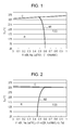
- Fig. 1 illustrates a phase diagram that employs a composition ratio of a first component and a second component for the horizontal axis and temperature for the vertical axis when the first component is (Bi, Na, La)TiO 3 and the second component is NaNbO 3 .
- the Curie temperature Tc of (Bi, Na, La)TiO 3 that is the first component is 335°C
- the Curie temperature of NaNbO 3 that is the second component is 365°C
- the MPB line M1 is substantially vertically erect
- a composition ratio of (Bi, Na, La)TiO 3 merely changes in the range of 0.6 to 0.5.
- the Curie temperature Tc3 at the peak of the MPB line M1 is 330°C. Accordingly, a piezoelectric material that has a remarkable piezoelectric characteristic and dielectric characteristic in a wide use environment temperature range and has a high Curie temperature can be realized.
- Fig. 2 illustrates a phase diagram that employs a composition ratio of a first component and a second component for the horizontal axis and temperature for the vertical axis when the first component is (Bi, Na, La)TiO 3 and the second component is (K, Na)NbO 3 to which at least one of Li and Ta has been added.
- the Curie temperature Tc of (Bi, Na, La)TiO 3 that is the first component is 335°C
- the Curie temperature Tc of (K, Na)NbO 3 to which at least one of Li and Ta that is the second component is 325°C
- the MPB line M2 is substantially vertically erect
- a composition ratio of (Bi, Na, La)TiO 3 merely changes in the range of 0.46 to 0.63.
- the Curie temperature Tc3 at the peak of the MPB line M2 is 330°C. Accordingly, a piezoelectric material that has a remarkable piezoelectric characteristic and dielectric characteristic in a wide use environment temperature range and has a high Curie temperature can be realized.
- Fig. 3 illustrates a phase diagram that employs a composition ratio of a first component and a second component for the horizontal axis and temperature for the vertical axis when the first component is (Bi, Na, La)TiO 3 and the second component is (Bi, K)TiO 3 .
- the Curie temperature Tc of (Bi, Na, La)TiO 3 that is the first component is 335°C
- the Curie temperature Tc of (Bi, K)TiO 3 that is the second component is 380°C
- the MPB line M3 is substantially vertically erect
- a composition ratio of (Bi, Na, La)TiO 3 merely changes in the range of 0.35 to 0.31.
- the Curie temperature Tc3 at the peak of the MPB line M3 is 347°C. Accordingly, a piezoelectric material that has a remarkable piezoelectric characteristic and dielectric characteristic in a wide use environment temperature range and has a high Curie temperature can be realized.
- the first component is (Bi, Na, Ba)TiO 3 , (Bi, Na)TiO 3 , and one selected from (Bi, Na, Ba)TiO 3 to which Ca is added, (Bi, La)(St, Ti)O 3 , and (Bi, Na)(Sc, Ti)O 3
- the second component is (K, Na) NbO 3 to which at least one selected from Li and Ta is added
- a phase diagram similar to Figs. 1 to 3 is obtained, the MPB line is substantially vertically erect, and a piezoelectric material that has a remarkable piezoelectric characteristic and dielectric characteristic in a wide use environment temperature range and has a high Curie temperature can be realized.
- the phase diagram includes a composition range (denoted by R in the drawing) formed as a rhombohedral crystal, a composition range formed as a tetragonal crystal (denoted by T in the drawing) or an orthorhombic crystal (denoted by O in the drawing), and a composition range formed as a cubic crystal (denoted by C in the drawing).
- the range of the piezoelectric coefficient d33 is preferably 100 to 300 pC/N, and more preferably 150 to 300 pC/N.
- the range of the Young's modulus is preferably 30 to 80 GPa
- the range of the Curie temperature Tc is preferably 70 to 350°C and more preferably 100 to 300°C.
- the range of relative permittivity is preferably equal to or less than 2000 and more preferably 100 to 1000.
- the range of the e constant is preferably 3 to 15 C/m 2 and more preferably 5 to 15 C/m 2 .
- the range of the Young's modulus is preferably 70 to 150 GPa and more preferably 80 to 130 GPa.
- the range of the Curie temperature Tc is preferably 100 to 350°C and more preferably 120 to 300°C.
- the range of relative permittivity is preferably equal to or less than 2000 and more preferably 100 to 800.
- Fig. 4 is an exploded perspective view illustrating a schematic configuration of an ink jet type recording head that is an example of a liquid ejecting head equipped with the piezoelectric element according to an embodiment of the invention.
- Fig. 5 is a plan view of Fig. 4
- Fig. 6 is a cross-sectional view taken by cutting along the line VI-VI of Fig. 5 .
- a flow path forming substrate 10 of the present embodiment is constituted by a silicon monocrystal substrate, and an elastic film 50 configured to have silicon dioxide is formed on one face of the substrate.
- a plurality of pressure generating chambers 12 are provided in parallel in the flow path forming substrate 10 in the width direction of the substrate.
- a communication unit 13 is formed in an outer region of the pressure generating chambers 12 in the longitudinal direction of the flow path forming substrate 10, and the communication unit 13 and each of the pressure generating chambers 12 communicate with each other via ink supply paths 14 and communication paths 15 provided for each of the pressure generating chambers 12.
- the communication unit 13 constitutes a part of a manifold that serves as an ink chamber shared by the pressure generating chambers 12 by communicating with a manifold unit 31 of a protection substrate to be described later.
- the ink supply paths 14 are formed having widths narrower than the pressure generating chambers 12, and keep resistance of ink flowing from the communication unit 13 to the pressure generating chambers 12 against the flow path constant. Note that, in the present embodiment, the ink supply paths 14 are formed by narrowing the width of the flow path from a single side, but the ink supply paths may be formed by narrowing the width of the flow path from both sides. In addition, the ink supply paths may be formed not by narrowing the width of the flow path but by narrowing the width in the thickness direction thereof. In the present embodiment, a liquid flow path constituted by the pressure generating chambers 12, the communication unit 13, the ink supply paths 14, and the communication paths 15 is provided in the flow path forming substrate 10.
- a nozzle plate 20 in which nozzle openings 21, which communicate with the pressure generating chambers 12 near the edge on the opposite side of the ink supply paths 14, are drilled is fixed to the flow path forming substrate 10 on the opening face side using an adhesive, a thermal welding film, or the like.
- the nozzle plate 20 is formed of, for example, glass ceramics, silicon monocrystal substrate, stainless steel, or the like.
- the elastic film 50 described above is formed, and an adhesive layer 56 that is formed of titanium oxide for improving adhesiveness to a base of first electrodes 60, such as the elastic film 50, is provided on the elastic film 50.
- an insulating film formed of zirconium oxide may be formed between the elastic film 50 and the adhesive layer 56 if necessary.
- the first electrodes 60, a piezoelectric layer 70 which is a thin film having a thickness being equal to or thinner than 2 ⁇ m, or preferably 0.3 to 1.5 ⁇ m, and second electrodes 80 are formed on the adhesive layer 56 in a laminating manner, configuring piezoelectric elements 300.
- the piezoelectric element 300 refers to a portion including the first electrodes 60, the piezoelectric layer 70, and the second electrodes 80.
- one electrode of the electrodes of the piezoelectric elements 300 is set to be a shared electrode, and the other electrode and the piezoelectric layer 70 are patterned for each of the pressure generating chambers 12.
- the first electrode 60 is set to be a shared electrode of the piezoelectric elements 300
- each of the second electrodes 80 is set to be an independent electrode of the piezoelectric elements 300, but it does not matter to reverse the setting according to a state of a drive circuit or a wiring.
- the piezoelectric elements 300 and a diaphragm of which displacement is caused due to driving of the piezoelectric elements 300 are referred to as actuator devices.
- the elastic film 50, the adhesive layer 56, the first electrodes 60, and an insulating film provided if necessary act as a diaphragm, but it is of course not limited thereto, and for example, the elastic film 50 or the adhesive layer 56 need not be provided.
- the piezoelectric elements 300 may also serve as a substantial diaphragm by themselves.
- the piezoelectric layer 70 is formed of the piezoelectric material of the invention described above. Since the piezoelectric material has a remarkable piezoelectric characteristic and dielectric characteristic in a wide use environment temperature range and has a high Curie temperature, a piezoelectric element that exhibits an excellent displacement characteristic in a wide use environment temperature range can be realized. In addition, since the piezoelectric material does not contain lead, an environmental burden can be reduced.
- Each of the second electrodes 80 that is an independent electrode of the piezoelectric elements 300 is drawn out from a periphery of an end of the ink supply path 14, and is connected to one of the leading electrodes 90 that are formed of, for example, gold (Au), or the like, extending onto the adhesive layer 56.
- Au gold
- a protection substrate 30 that has the manifold unit 31 constituting at least a part of a manifold 100 is bonded via an adhesive 35.
- the manifold unit 31 is formed passing through the protection substrate 30 in the thickness direction thereof to the side of the pressure generating chambers 12, and communicates with the communication unit 13 of the flow path forming substrate 10 described above, thereby constituting the manifold 100 that serves as a shared ink chamber of the pressure generating chambers 12 in the present embodiment.
- the manifold unit 31 need be set to be a manifold.
- the ink supply path 14 that communicates with the manifold 100 and the pressure generating chambers 12 may be provided in a member (for example, the elastic film 50, the adhesive layer 56, or the like) that is interposed between the flow path forming substrate 10 and the protection substrate 30.
- a piezoelectric element holding unit 32 that has a space large enough for not disrupting motions of the piezoelectric elements 300 is provided.
- the piezoelectric element holding unit 32 preferably has a space large enough for not disrupting motions of the piezoelectric elements 300, and the space may or may not be sealed.
- the protection substrate 30 described above a material having substantially the same thermal expansion coefficient as the flow path forming substrate 10, for example, glass, a ceramic material, or the like is preferably used, and in the present embodiment, the projection substrate is formed using a silicon monocrystal substrate that is the same material as the flow path forming substrate 10.
- a through hole 33 passing through the protection substrate 30 in the thickness direction is provided in the protection substrate 30.
- a part of an end of the leading electrode 90 drawn from each of the piezoelectric elements 300 is provided so as to be exposed within the through hole 33.
- a drive circuit 120 for driving the piezoelectric elements 300 which are installed in parallel with each other is fixed onto the protection substrate 30.
- the drive circuit 120 for example, a circuit board, a semiconductor integrated circuit (IC), or the like can be used.
- the drive circuit 120 and the leading electrode 90 are electrically connected to each other via connection wiring 121 formed of conductive wires such as bonding wires.
- a compliance substrate 40 that includes a sealing film 41 and a fixing plate 42 is bonded with the protection substrate 30.
- the sealing film 41 is formed of a flexible material having low rigidity, and one face of the manifold unit 31 is sealed by the sealing film 41.
- the fixing plate 42 is formed of a relatively hard material. Since a region of the fixing plate 42 facing the manifold 100 forms an opening 43 which is completely removed in the thickness direction, one face of the manifold 100 is sealed only by the flexible sealing film 41.
- ink is taken from an ink inlet connected to an external ink supply unit that is not shown in the drawing, the inside from the manifold 100 to nozzle openings 21 is filled with ink, then a voltage is applied between the first electrodes 60 and the second electrodes 80 each of which is corresponding to the pressure generating chambers 12 according to a recording signal from the drive circuit 120, and accordingly, the elastic film 50, the adhesive layer 56, the first electrodes 60, and the piezoelectric layer 70 are deflected, which causes pressure inside each of the pressure generating chambers 12 to increase, and consequently ink drops are discharged from the nozzle openings 21.
- a silicon dioxide film formed of silicon dioxide (SiO 2 ), or the like constituting the elastic film 50 is formed on a surface of a wafer for a flow path forming substrate that is a silicon wafer using thermal oxidation or the like.
- the adhesive layer 56 formed of titanium oxide, or the like is formed on the elastic film 50 (silicon dioxide film) using a reactive sputtering method, thermal oxidation, or the like.
- the first electrodes 60 are formed on the adhesive layer 56.
- the first electrodes 60 that is formed of platinum, indium, indium oxide, a laminated structure thereof, or the like is formed on the adhesive layer 56.
- the adhesive layer 56 and the first electrodes 60 can be formed using, for example, a sputtering method or a vapor deposition method.
- the piezoelectric layer 70 is laminated on the first electrode 60.
- a manufacturing method of the piezoelectric layer 70 is not particularly limited, but for example, the piezoelectric layer 70 can be formed using a chemical solution method such as a Metal-Organic Decomposition (MOD) method or a gel-sol method in which a solution obtained by dissolving or dispersing an organic metal compound in a solvent is applied, dried, and then burned at a high temperature, and thereby the piezoelectric layer 70 formed of metal oxide is obtained.
- the piezoelectric layer 70 may be formed using other methods including a laser ablation method, the sputtering method, a pulsed laser deposition method (PLD method), a CVD method, an aerosol deposition method, or the like.
- 2-ethylhexanoate, acetate containing desired elements are used as starting materials.
- these are bismuth 2-ethylhexanoate, barium 2-ethylhexanoate, iron 2-ethylhexanoate, titanium 2-ethylhexanate, and the like.
- a precursor solution is prepared by mixing n-octane solutions of the raw materials, and adjusting molar ratios of metal elements so as to match with a stoichiometric ratio.
- a piezoelectric film is formed using a spin coating method in which the precursor solution is dropped onto a bottom electrode that is produced beforehand, rotated for 6 seconds at 500 rpm, and then a substrate is rotated for 20 seconds at 3000 rpm. Next, the substrate is placed on a hot plate, and dried for 2 minutes at 180°C. Next, the substrate is placed on the hot plate, and then degreasing is performed for 2 minutes at 350°C. After repeating the process from solution application to degreasing (so that the process is carried out twice), the substrate is fired for 5 minutes at 750°C using an RTA device in an oxygen atmosphere. Then, the whole process is repeated four more times (that is, it is carried out a total of five times), and thereby a piezoelectric layer 70 can be formed through a total of 10 times of application.
- a spin coating method in which the precursor solution is dropped onto a bottom electrode that is produced beforehand, rotated for 6 seconds at 500 rpm, and then a substrate is rotated for 20 seconds
- the second electrodes 80 formed of platinum, or the like are formed on the piezoelectric layer 70 using the sputtering method, or the like, the piezoelectric layer 70 and the second electrodes 80 are patterned at the same time in a region facing each of the pressure generating chambers 12, and thereby the piezoelectric elements 300 configured to have the first electrodes 60, the piezoelectric layers 70, and the second electrodes 80 are formed.
- the patterning of the piezoelectric layer 70 and the second electrode 80 can be collectively performed using dry etching via a resist (not shown in the drawing) that is formed in a predetermined shape.
- post annealing may be performed in a temperature range of 600°C to 800°C if necessary. Accordingly, a favorable interface between the piezoelectric layer 70 and the first electrodes 60 or the second electrodes 80 can be formed, and a crystalline property of the piezoelectric layer 70 can improve.
- the leading electrodes 90 formed of, for example, gold (Au), or the like are formed, and then, the electrodes are patterned for each of the piezoelectric elements 300 via, for example, a mask pattern that includes a resist, or the like.
- the wafer for the flow path forming substrate is thinned so as to have a predetermined thickness.
- a mask film is newly formed on the wafer for the flow path forming substrate, and patterned in a predetermined shape.
- the pressure generating chambers 12, the communication unit 13, the ink supply path 14, and the communication path 15 corresponding to the piezoelectric elements 300 are formed.
- a precursor solution was prepared by mixing n-octane solutions of bismuth 2-ethylhexanoate, sodium 2-ethylhexanoate, lanthanum 2-ethylhexanoate, titanium 2-ethylhexanoate, and niobium 2-ethylhexanoate as starting materials by adjusting the molar ratio of the metal elements so as to match with a stoichiometric ratio of the composition.
- a piezoelectric film was formed using a spin coating method in which the precursor solution was dropped onto a bottom electrode that had been produced beforehand, rotated for 6 seconds at 500 rpm, and then a substrate was rotated for 20 seconds at 3000 rpm. Next, the substrate was placed on a hot plate and dried for 2 minutes at 180°C. Then, the substrate was placed on the hot plate to perform degreasing for 2 minutes at 350°C. After repeating the process from solution application to degreasing so that the process was carried out twice, the substrate was burned for 5 minutes at 750°C using an RTA device in an oxygen atmosphere. Then, the process was repeated four more times so that the process was carried out a total of five times, and thereby a piezoelectric layer was formed through a total of 10 times of application.
- a head with the structure described above was configured using piezoelectric elements formed using the piezoelectric layer.
- d33 of the piezoelectric element was 180 pC/N, and the Young's modulus thereof was 77 GPa.
- the Curie temperature Tc was 330°C.
- (Bi 0.5 , Na 0.4 , La 0.1 )TiO 3 was selected as the first component
- (K 0.5 , Na 0.5 )NbO 3 to which at least one element selected from Li and Ta had been added was selected as the second component
- a piezoelectric material having a composition in which the molar ratio of both components is 0.45:0.55 was formed as described below.
- a precursor solution was prepared by mixing n-octane solutions of bismuth 2-ethylhexanoate, sodium 2-ethylhexanoate, lanthanum 2-ethylhexanoate, titanium 2-ethylhexanoate, potassium 2-ethylhexanoate, niobium 2-ethylhexanoate, lithium 2-ethylhexanoate, and tantalum 2-ethylhexanoate as starting materials by adjusting the molar ratio of the metal elements so as to match with a stoichiometric ratio of the composition.
- a piezoelectric film was formed using the spin coating method in which the precursor solution was dropped onto a bottom electrode that had been produced beforehand, rotated for 6 seconds at 500 rpm, and then a substrate was rotated for 20 seconds at 3000 rpm. Next, the substrate was placed on a hot plate and dried for 2 minutes at 180°C. Then, the substrate was placed on the hot plate to perform degreasing for 2 minutes at 350°C. After repeating the process from solution application to degreasing so that the process was carried out twice, the substrate was burned for 5 minutes at 750°C using an RTA device in an oxygen atmosphere. Then, the process was repeated four more times so that the process was carried out a total of five times, and thereby a piezoelectric layer was formed through a total of 10 times of application.
- a head with the structure described above was configured using piezoelectric elements formed using the piezoelectric layer.
- d33 of the piezoelectric element was 220 pC/N, and the Young's modulus thereof was 70 GPa.
- the Curie temperature Tc4 was 330°C.
- a precursor solution was prepared by mixing n-octane solutions of bismuth 2-ethylhexanoate, sodium 2-ethylhexanoate, lanthanum 2-ethylhexanoate, titanium 2-ethylhexanoate, and potassium 2-ethylhexanoate as starting materials by adjusting the molar ratio of the metal elements so as to match with a stoichiometric ratio of the composition.
- a piezoelectric film was formed using the spin coating method in which the precursor solution was dropped onto a bottom electrode that had been produced beforehand, rotated for 6 seconds at 500 rpm, and then a substrate was rotated for 20 seconds at 3000 rpm. Next, the substrate was placed on a hot plate and dried for 2 minutes at 180°C. Then, the substrate was placed on the hot plate to perform degreasing for 2 minutes at 350°C. After repeating the process from solution application to degreasing so that the process was carried out twice, the substrate was burned for 5 minutes at 750°C using an RTA device in an oxygen atmosphere. Then, the process was repeated four more times so that the process was carried out a total of five times, and thereby a piezoelectric layer was formed through a total of 10 times of application.
- a head with the structure described above was configured using piezoelectric elements formed using the piezoelectric layer.
- d33 of the piezoelectric element was 270 pC/N, and the Young's modulus thereof was 75 GPa.
- the Curie temperature Tc4 was 347°C.
- 2-ethylhexanoate was employed as a starting material.
- An n-octane solution was employed as a solvent, they were mixed by adjusting the molar ratio of the metal elements so as to match with a stoichiometric ratio of the composition, and accordingly, a precursor solution was prepared.
- An MPB is not always formed only in a combination of a rhombohedral crystal and a tetragonal crystal. Although there are differences in the effect of the MPB, there are the following combination cases.
- Table 1 describes compositions (A site and B site) composing a perovskite-type crystal (ABO 3 wherein A and B are metal elements), crystal systems, and the Curie temperature Tc thereof.
- the elements can be arbitrarily selected so that a combination of different crystal systems from Table 1 can be realized. In this case, Tc1 and Tc2, can fall within the claims by adjusting an additive and an amount of addition.
- elements appropriate for the additive elements other than the elements described in Table 1 are exemplified below: Mn, Ge, Si, B, Cu, and Ag.
- a basic configuration of the invention is not limited to one described above.
- a silicon monocrystal substrate is exemplified as the flow path forming substrate 10 in the embodiment described above, the configuration is not particularly limited thereto, and a material, for example, an SOI substrate, glass, or the like may be used.
- the piezoelectric elements 300 obtained by laminating the first electrodes 60, the piezoelectric layer 70, and the second electrodes 80 on a substrate (the flow path forming substrate 10) in order are exemplified, they are not particularly limited thereto, and the invention can also be applied to a longitudinal oscillation type piezoelectric element in which piezoelectric materials and electrode forming materials are laminated in an alternate manner and extend in an axial direction.
- the piezoelectric layer need not be a thin film as described above, but may be a bulk.
- carbonate or oxide can be used as a starting material. Examples are K 2 CO 3 , Na 2 CO 3 , Nb 2 O 5 , and the like.
- the starting materials are measured so as to match with a stoichiometric ratio and then wet-blended with ethanol using a ball mill. After the obtained mixture is dried, it is calcined for 3 hours at 700°C.
- the calcined powder is pulverized and mixed using mortar with addition of an appropriate amount of PVA as a binder, and is caused to pass through a sieve of 150 mesh to adjust granularity thereof, and then the obtained power is formed into a discoid pallet using a single-axis press device.
- the formed pallet and residual calcined power are put into a melting pot and burned for 3 hours at 1100°C, thereby obtaining a discoid oxide.
- both faces of the obtained discoid oxide are polished so as to have surfaces, are coated with silver paste and burned, and accordingly, a piezoelectric body provided with silver electrodes can be obtained.
- barium carbonate titanium oxide, bismuth oxide, tin oxide, iron oxide, zirconium oxide, lanthanum oxide, lithium carbonate, and the like can be exemplified as starting materials.
- the ink jet type recording head of the embodiment can constitute a part of a recording head unit that includes an ink flow path that communicates with an ink cartridge, or the like, and can be mounted in an ink jet type recording apparatus.
- Fig. 7 is a schematic diagram illustrating an example of such an ink jet type recording apparatus.
- recording head units 1A and 1B that have the ink jet type recording head I are provided so as to enable cartridges 2A and 2B constituting an ink supply unit to attach to and detach from the units, and a carriage 3 on which the recording head units 1A and 1B are mounted is provided so as to freely move on a carriage shaft 5 installed in the main body 4 of the apparatus in the axial direction.
- the recording head units 1A and 1B are respectively set to discharge, for example, a black ink composition and a color ink composition.
- a drive motor 6 is transmitted to the carriage 3 via a plurality of gear wheels, which are not shown in the drawing, and a timing belt 7, and accordingly, the carriage 3 on which the recording head units 1A and 1B are mounted is moved along the carriage shaft 5.
- the main body 4 of the apparatus is provided with a platen 8 along the carriage shaft 5, and a recording sheet S that is a recording medium such as paper fed by a feeding roller, or the like, which is not shown in the drawing, is designed to be wound around the platen 8 and then transported.
- the ink jet type recording head units 1A and 1B are set to respectively have one ink jet type recording head I, they are not particularly limited thereto, and for example, either of the ink jet type recording head units 1A or 1B may have two or more ink jet type recording heads.
- the ink jet type recording head is exemplified as an example of a liquid ejecting head
- the invention widely targets liquid ejecting heads in general, and can of course be applied to liquid ejecting heads that eject liquid other than ink.
- liquid ejecting heads for example, various recording heads used in image recording apparatuses such as printers, color material ejecting heads used in manufacturing of color filters of liquid crystal displays, electrode material ejecting heads used in formation of electrodes of organic EL displays, and field emission displays (FED), bioorganic substance ejecting heads used in manufacturing of bio chips, and the like can be exemplified.
- the piezoelectric element of the invention exhibits a satisfactory insulating property and piezoelectric characteristic, it can be applied to a piezoelectric element of a liquid ejecting head represented by an ink jet-type recording head as described above, however, it is not limited thereto. Since the piezoelectric element of the invention exhibits an excellent displacement characteristic, it is not limited to the liquid ejecting head represented by an ink jet-type recording head, it can be appropriately used by being mounted on liquid ejecting apparatuses, ultrasonic sensors, piezoelectric motors, ultrasonic motors, piezoelectric transformers, oscillation-type dust removal apparatuses, pressure-electric converters, ultrasonic wave transmitting machines, pressure sensors, acceleration sensors, or the like.
- the piezoelectric element of the invention exhibits a satisfactory energy-electric conversion capability, it can be appropriately used by being mounted on a power generator.
- the power generator include a power generator using a pressure-electric conversion effect, a power generator using an electronic excitation (photovoltaic power) by light, a power generator using an electronic excitation (thermo-electric force) by heat, and a power generator using oscillating.
- the piezoelectric element of the invention can be appropriately used in pyroelectric devices such as infrared detectors, terahertz detectors, temperature sensors, and thermo-sensitive sensors or ferroelectric elements such as a ferroelectric memory.
Landscapes
- Engineering & Computer Science (AREA)
- Chemical & Material Sciences (AREA)
- Ceramic Engineering (AREA)
- Materials Engineering (AREA)
- Organic Chemistry (AREA)
- Manufacturing & Machinery (AREA)
- Structural Engineering (AREA)
- Multimedia (AREA)
- Acoustics & Sound (AREA)
- Physics & Mathematics (AREA)
- Particle Formation And Scattering Control In Inkjet Printers (AREA)
- Compositions Of Oxide Ceramics (AREA)
- Formation Of Insulating Films (AREA)
Abstract
Description
- The present invention relates to a piezoelectric material used in piezoelectric elements, or the like mounted in various devices such as actuators, ultrasonic devices such as ultrasonic oscillators, ultrasonic motors, pressure sensors, and pyroelectric elements such as IR sensors, a piezoelectric element using the material, a liquid ejecting head, a liquid ejecting apparatus, an ultrasonic sensor, a piezoelectric motor, and a power generator.
- In the related art, a piezoelectric material, which is used as a piezoelectric layer (piezoelectric ceramics) constituting a piezoelectric element, or the like mounted in various devices such as actuators, ultrasonic devices such as ultrasonic oscillators, ultrasonic motors, pressure sensors, and pyroelectric elements such as IR sensors is required to have a remarkable piezoelectric characteristic, and as a representative example thereof, lead zirconate titanate (PZT) is exemplified.
- However, from an environmental problem point of view, a piezoelectric material whose lead content is suppressed is required. As such a lead-free piezoelectric material, there are a piezoelectric material that includes an alkali metal such as KxNa(1-x)NbO3, and (Ba, Na)TiO3, a piezoelectric material such as BiFeO3-BaTiO3, and the like.
- With regard to such a piezoelectric material, it is known that a remarkable piezoelectric characteristic can be obtained by using a composition near a Morphotropic Phase Boundary (MPB). However, in a phase diagram that employs compositions for the horizontal axis and temperatures for the vertical axis, the MPB line of PZT is positioned substantially in parallel to the axis of temperature or positioned vertical to the axis of composition, but an MPB line of a lead-free piezoelectric material is generally inclined with respect to the axis of temperature (for example, refer to
Fig. 1 ofJP-A-2009-215111 - Thus, from a desire that the MPB line is erect if possible in the phase diagram described above and a desire that a piezoelectric material has a remarkable piezoelectric characteristic and dielectric characteristic at around a normal temperature and can be used even at a temperature as high as possible, a piezoelectric material that has Curie temperature (Tc) as high as it can be, which is generally inversely proportional to the piezoelectric characteristic, has been demanded.
- For this reason, technologies for improving temperature dependency by laminating a plurality of piezoelectric materials having different compositions have been proposed (refer to
JP-A-2003-277143 JP-A-2011-181764 - As described above, currently, there is no lead-free piezoelectric material comparable to PZT, and thus, introduction of a lead-free piezoelectric material having a remarkable piezoelectric characteristic and dielectric characteristic in a wide use environment temperature range and having a high Curie temperature has been greatly desired.
- Note that such a problem also arises not only in ink jet-type recording heads but also in other liquid ejecting heads that discharge droplets other than ink, and also arises even in piezoelectric elements used in devices other than such liquid ejecting heads.
- An advantage of some aspects of the invention is to provide a piezoelectric material that reduces the burden on the environment, and has a remarkable piezoelectric characteristic and dielectric characteristic in a wide use environment temperature range and has a high Curie temperature, a piezoelectric element using the material, a liquid ejecting head, a liquid ejecting apparatus, an ultrasonic sensor, a piezoelectric motor, and a power generator.
- According to an aspect of the invention, there is provided a piezoelectric material containing a first component that is a rhombohedral crystal in a single composition and that is configured to have a complex oxide with a perovskite structure and Curie temperature is set to be Tc1 and a second component that is a crystal other than a rhombohedral crystal and that is configured to have a complex oxide with the perovskite structure and Curie temperature is set to be Tc2, and in which the absolute value of the difference between Tc1 and Tc2 |Tc1-Tc2| is equal to or lower than 50°C.
- In this case, since the piezoelectric material does not contain lead, an environmental burden can be reduced, and the piezoelectric material that has a remarkable piezoelectric characteristic and dielectric characteristic in a wide use environment temperature range and has a high Curie temperature is produced.
- Here, it is preferable that a composition near an MPB line be provided in a phase diagram that employs a composition ratio of a first component and a second component for the horizontal axis and temperature for the vertical axis. In this case, by selecting each component, the piezoelectric material that has a remarkable piezoelectric characteristic and dielectric characteristic in a use environment temperature range and has a high Curie temperature can be realized, in a wide composition range.
- In addition, it is preferable that the relationship of |Tc1-Tc2| / |Tc1+Tc2|≤0.1 be satisfied. Accordingly, by further limiting the range of the absolute value of the difference between Tc1 and Tc2 |Tc1-Tc2|, the piezoelectric material that has a remarkable piezoelectric characteristic and dielectric characteristic in a wide use environment temperature range and has a high Curie temperature can realized more reliably.
- In addition, it is preferable that Curie temperature be equal to or higher than 280°C. In this case, the piezoelectric material that can be used in a wide use environment temperature range can be realized.
- In addition, it is preferable that the molar ratio of the first component to (the first component+the second component) be equal to or higher than 0.1 and equal to or lower than 0.9. In this case, by selecting each component, the piezoelectric material that has a remarkable piezoelectric characteristic and dielectric characteristic in a wide use environment temperature range and has a high Curie temperature can be realized in a wide composition range.
- Alternatively, it is preferable that the first component be (Bi, Na, La)TiO3, and the second component be NaNbO3. In this case, a piezoelectric material that has a remarkable piezoelectric characteristic and dielectric characteristic in a wide use environment temperature range and has a high Curie temperature can be realized more reliably.
- Alternatively, it is preferable that the first component be (Bi, Na, La)TiO3, and the second component be (K, Na)NbO3 to which at least one kind selected from Li and Ta is added. In this case, a piezoelectric material that has a remarkable piezoelectric characteristic and dielectric characteristic in a wide use environment temperature range and has a high Curie temperature can be realized more reliably.
- Alternatively, it is preferable that the first component be (Bi, Na, La)TiO3, and the second component be (Bi, K)TiO3. In this case, a piezoelectric material that has a remarkable piezoelectric characteristic and dielectric characteristic in a wide use environment temperature range and has a high Curie temperature can be realized more reliably.
- Alternatively, it is preferable that the first component be (Bi, Na, Ba)TiO3, (Bi, Na)TiO3, and one kind selected from (Bi, Na)TiO3, (Bi, La)(Sc, Ti)O3, and (Bi, La)(Zn, Ti)O3 to which Ca is added, and the second component be NaNbO3 to which at least one kind selected from Li and Ta is added. In this case, a piezoelectric material that has a remarkable piezoelectric characteristic and dielectric characteristic in a wide use environment temperature range and has a high Curie temperature can be realized more reliably.
- According to another aspect of the invention, there is provided a piezoelectric element which includes a piezoelectric layer configured to have the piezoelectric material according to the aspect described above and an electrode provided on the piezoelectric layer.
- In this case, since the piezoelectric element does not contain lead, an environmental burden can be reduced, and the piezoelectric material that can maintain excellent characteristics in a wide use environment temperature range can be realized.
- In addition, according to still another aspect of the invention, there is provided a liquid ejecting head that includes a pressure generating chamber that communicates with a nozzle opening and a piezoelectric element that has a piezoelectric layer and an electrode provided on the piezoelectric layer, and the piezoelectric layer is formed of the piezoelectric material according to the above-described aspect.
- In this case, since the piezoelectric element does not contain lead, an environmental burden can be reduced, and the liquid ejecting head that includes a piezoelectric element that can maintain excellent characteristics in a wide use environment temperature range can be realized.
- In addition, according to still another aspect of the invention, there is provided a liquid ejecting apparatus that includes the liquid ejecting head according to the above-described aspect.
- In this case, since the piezoelectric element does not contain lead, an environmental burden can be reduced, and the liquid ejecting apparatus equipped with a liquid ejecting head that includes a piezoelectric element that can maintain excellent characteristics in a wide use environment temperature range can be realized.
- In addition, according to still another aspect of the invention, there is provided an ultrasonic sensor that includes a vibrating unit that transmits a displacement which is caused due to driving of the piezoelectric element according to the above-described aspect to the outside and a matching layer that transmits a generated pressure wave to the outside.
- In this case, since the piezoelectric element does not contain lead, an environmental burden can be reduced, and the ultrasonic sensor equipped with a piezoelectric element that can maintain excellent characteristics in a wide use environment temperature range can be realized.
- In addition, according to still another aspect of the invention, there is provided a piezoelectric motor that includes at least a vibrator in which the piezoelectric element according to the above-described aspect is arranged, and a moving body contacting the vibrator.
- In this case, since the piezoelectric element does not contain lead, an environmental burden can be reduced, and the piezoelectric motor equipped with a piezoelectric element that can maintain excellent characteristics in a wide use environment temperature range can be realized.
- In addition, according to still another aspect of the invention, there is provided a power generator that includes an electrode for taking out a charge generated by the piezoelectric element according to the above-described aspect from the electrode.
- In this case, since the piezoelectric element does not contain lead, an environmental burden can be reduced, and the power generator equipped with a piezoelectric element that can maintain excellent characteristics in a wide use environment temperature range can be realized.
- Embodiments of the invention will now be described by way of example only with reference to the accompanying drawings, wherein like numbers reference like elements.
-
Fig. 1 is a graph plotting an example of a phase diagram for describing a piezoelectric material according to an aspect of the invention. -
Fig. 2 is a graph plotting an example of a phase diagram for describing the piezoelectric material according to the aspect of the invention. -
Fig. 3 is a graph plotting an example of a phase diagram for describing the piezoelectric material according to the aspect of the invention. -
Fig. 4 is an exploded perspective view illustrating a schematic configuration of a recording head according to a first embodiment of the invention. -
Fig. 5 is a plan view of the recording head according to the first embodiment of the invention. -
Fig. 6 is a cross-sectional view of the recording head according to the first embodiment of the invention. -
Fig. 7 is a diagram illustrating a schematic configuration of a recording apparatus according to an embodiment of the invention. - Hereinafter, the invention will be described in detail based on embodiments. Piezoelectric Material
- A piezoelectric material of the invention contains a first component that is a rhombohedral crystal in a single composition, that is configured to comprise a complex oxide with a perovskite structure and that has the Curie temperature set to be Tc1 and a second component that is a crystal other than the rhombohedral crystal in a single composition, that is configured to comprise a complex oxide with the perovskite structure and that has the Curie temperature set to be Tc2, and the absolute value of the difference between Tc1 and Tc2 |Tc1-Tc2| is equal to or lower than 50°C.
- In the invention, with the piezoelectric material which is obtained by forming a solid solution of the first component and the second component which satisfy the above condition, an MPB line can be made substantially vertically erect in a phase diagram that employs a composition ratio of the first component and the second component for the horizontal axis and temperature for the vertical axis.
- Here, the first component is the rhombohedral crystal and is a complex oxide with the perovskite structure and has a relatively high Curie temperature, and for example, (Bi, Na, La)TiO3, (Bi, Na, Ba)TiO3, (Bi, Na)TiO3, and (Bi, Na, Ba)TiO3 to which Ca is added, (Bi, La)(St, Ti)O3, and (Bi, Na)(Sc, Ti)O3, Bi(FeMn)O3, and the like can be exemplified.
- The second component is a crystal other than the rhombohedral crystal, in other words, a tetragonal crystal or an orthorhombic crystal, and has a relatively high Curie temperature, and NaNbO3, (K, Na)NbO3, (Bi, K)TiO3, and NaTaO3 to which at least one selected from Li and Ta is added, and the like can be exemplified.
- Here in a phase diagram that employs a composition ratio of the first component and the second component for the horizontal axis and temperature for the vertical axis, a line connecting Tc1 of the first component that is the rhombohedral crystal and Tc2 of the second component of a crystal other than the rhombohedral crystal, for example, a tetragonal crystal is positioned substantially in parallel to the axis of the composition ratio. This is because the composition is of a solid solution of the first component and the second component of which the absolute value of the difference between Tc1 and Tc2 |Tc1-Tc2| is equal to or lower than 50°C.
- Thus, by using the composition along the MPB line, a piezoelectric material of which the Curie temperature of the composition is equal to or higher than 280°C and which can maintain almost constant characteristics even when temperature of a use environment changes can be realized.
- As described above, the composition of the piezoelectric material of the invention is a composition in which the first component and the second component forms a solid solution as described above, a composition near the MPB line in the phase diagram that employs a composition ratio of the first component and the second component for the horizontal axis and temperature for the vertical axis, and the Curie temperature of the composition Tc3 is preferably equal to or higher than 280°C.
- Here, the MPB line is a boundary for creating different crystal systems, a crystal system has composition dependency, and a dielectric constant, a piezoelectric constant, and the Young's modulus have composition dependency. Thus, in a composition that forms the MPB line, a dielectric constant and a piezoelectric constant have a maximum value, and the Young's modulus has a minimum value. The invention defines a composition region for a dielectric constant and a piezoelectric constant in which the characteristics are exhibited within the range of 70% or more of a peak value (a value on the MPB), and a composition region for the Young's modulus in which the characteristic is within the range of 130% of the minimum value as compositions near the MPB.
- Here, the relationship of |Tc1-Tc2| / |Tc1+Tc2|≤0.1 is preferably satisfied. With the relationship, the absolute value of the difference between Tc1 and Tc2 |Tc1-Tc2| is within a predetermined range, and preferably, the Curie temperature of the composition Tc3 is assuredly equal to or higher than 280°C.
- Here, it is preferable that the molar ratio of the first component to (the first component+the second component) be equal to or higher than 0.1 and equal to or lower than 0.9. By appropriately selecting the first component and the second component, a piezoelectric material that has a high Curie temperature Tc3, of preferably 280°C or higher in a wide composition range and can maintain characteristics almost constant even when temperature of a use environment changes can be realized.
- Examples of each of the first component and the second component which can be applied to the piezoelectric material of the invention are shown below.
- For example, the first component is (Bi, Na, La)TiO3 and the second component is NaNbO3.
- In addition, as one example the first component is (Bi, Na, La)TiO3 and the second component is (K, Na)NbO3 to which at least one kind selected from Li and Ta is added.
- In addition, as another example, the first component is (Bi, Na, La)TiO3 and the second component is (Bi, K)TiO3.
- In addition, the first component can be (Bi, Na, Ba)TiO3, (Bi, Na)TiO3, and one selected from (Bi, Na, Ba)TiO3 to which Ca is added, (Bi, La)(St, Ti)O3, and (Bi, Na)(Sc, Ti)O3, and the second component can be (K, Na)NbO3 to which at least one selected from Li and Ta is added.
- Hereinbelow, description will be provided in more detail with specific examples.
-
Fig. 1 illustrates a phase diagram that employs a composition ratio of a first component and a second component for the horizontal axis and temperature for the vertical axis when the first component is (Bi, Na, La)TiO3 and the second component is NaNbO3. In this case, the Curie temperature Tc of (Bi, Na, La)TiO3 that is the first component is 335°C, the Curie temperature of NaNbO3 that is the second component is 365°C, the MPB line M1 is substantially vertically erect, and a composition ratio of (Bi, Na, La)TiO3 merely changes in the range of 0.6 to 0.5. In addition, the Curie temperature Tc3 at the peak of the MPB line M1 is 330°C. Accordingly, a piezoelectric material that has a remarkable piezoelectric characteristic and dielectric characteristic in a wide use environment temperature range and has a high Curie temperature can be realized. -
Fig. 2 illustrates a phase diagram that employs a composition ratio of a first component and a second component for the horizontal axis and temperature for the vertical axis when the first component is (Bi, Na, La)TiO3 and the second component is (K, Na)NbO3 to which at least one of Li and Ta has been added. In this case, the Curie temperature Tc of (Bi, Na, La)TiO3 that is the first component is 335°C, the Curie temperature Tc of (K, Na)NbO3 to which at least one of Li and Ta that is the second component is 325°C, the MPB line M2 is substantially vertically erect, a composition ratio of (Bi, Na, La)TiO3 merely changes in the range of 0.46 to 0.63. In addition, the Curie temperature Tc3 at the peak of the MPB line M2 is 330°C. Accordingly, a piezoelectric material that has a remarkable piezoelectric characteristic and dielectric characteristic in a wide use environment temperature range and has a high Curie temperature can be realized. -
Fig. 3 illustrates a phase diagram that employs a composition ratio of a first component and a second component for the horizontal axis and temperature for the vertical axis when the first component is (Bi, Na, La)TiO3 and the second component is (Bi, K)TiO3. In this case, the Curie temperature Tc of (Bi, Na, La)TiO3 that is the first component is 335°C, the Curie temperature Tc of (Bi, K)TiO3 that is the second component is 380°C, the MPB line M3 is substantially vertically erect, and a composition ratio of (Bi, Na, La)TiO3 merely changes in the range of 0.35 to 0.31. In addition, the Curie temperature Tc3 at the peak of the MPB line M3 is 347°C. Accordingly, a piezoelectric material that has a remarkable piezoelectric characteristic and dielectric characteristic in a wide use environment temperature range and has a high Curie temperature can be realized. - Although not shown in the drawings, even when the first component is (Bi, Na, Ba)TiO3, (Bi, Na)TiO3, and one selected from (Bi, Na, Ba)TiO3 to which Ca is added, (Bi, La)(St, Ti)O3, and (Bi, Na)(Sc, Ti)O3, and the second component is (K, Na) NbO3 to which at least one selected from Li and Ta is added, a phase diagram similar to
Figs. 1 to 3 is obtained, the MPB line is substantially vertically erect, and a piezoelectric material that has a remarkable piezoelectric characteristic and dielectric characteristic in a wide use environment temperature range and has a high Curie temperature can be realized. Here, inFigs. 1 to 3 , the phase diagram includes a composition range (denoted by R in the drawing) formed as a rhombohedral crystal, a composition range formed as a tetragonal crystal (denoted by T in the drawing) or an orthorhombic crystal (denoted by O in the drawing), and a composition range formed as a cubic crystal (denoted by C in the drawing). - When the piezoelectric element is used as an actuator, the range of the piezoelectric coefficient d33 is preferably 100 to 300 pC/N, and more preferably 150 to 300 pC/N. In this case, the range of the Young's modulus is preferably 30 to 80 GPa, and the range of the Curie temperature Tc is preferably 70 to 350°C and more preferably 100 to 300°C. In addition, the range of relative permittivity is preferably equal to or less than 2000 and more preferably 100 to 1000.
- In addition, when the piezoelectric element is used as a sensor, the range of the e constant is preferably 3 to 15 C/m2 and more preferably 5 to 15 C/m2. In addition, in this case, the range of the Young's modulus is preferably 70 to 150 GPa and more preferably 80 to 130 GPa. In addition, the range of the Curie temperature Tc is preferably 100 to 350°C and more preferably 120 to 300°C. In addition, the range of relative permittivity is preferably equal to or less than 2000 and more preferably 100 to 800.
-
Fig. 4 is an exploded perspective view illustrating a schematic configuration of an ink jet type recording head that is an example of a liquid ejecting head equipped with the piezoelectric element according to an embodiment of the invention.Fig. 5 is a plan view ofFig. 4 , andFig. 6 is a cross-sectional view taken by cutting along the line VI-VI ofFig. 5 . As illustrated inFigs. 4 to 6 , a flowpath forming substrate 10 of the present embodiment is constituted by a silicon monocrystal substrate, and anelastic film 50 configured to have silicon dioxide is formed on one face of the substrate. - A plurality of
pressure generating chambers 12 are provided in parallel in the flowpath forming substrate 10 in the width direction of the substrate. In addition, acommunication unit 13 is formed in an outer region of thepressure generating chambers 12 in the longitudinal direction of the flowpath forming substrate 10, and thecommunication unit 13 and each of thepressure generating chambers 12 communicate with each other viaink supply paths 14 andcommunication paths 15 provided for each of thepressure generating chambers 12. Thecommunication unit 13 constitutes a part of a manifold that serves as an ink chamber shared by thepressure generating chambers 12 by communicating with amanifold unit 31 of a protection substrate to be described later. Theink supply paths 14 are formed having widths narrower than thepressure generating chambers 12, and keep resistance of ink flowing from thecommunication unit 13 to thepressure generating chambers 12 against the flow path constant. Note that, in the present embodiment, theink supply paths 14 are formed by narrowing the width of the flow path from a single side, but the ink supply paths may be formed by narrowing the width of the flow path from both sides. In addition, the ink supply paths may be formed not by narrowing the width of the flow path but by narrowing the width in the thickness direction thereof. In the present embodiment, a liquid flow path constituted by thepressure generating chambers 12, thecommunication unit 13, theink supply paths 14, and thecommunication paths 15 is provided in the flowpath forming substrate 10. - In addition, a
nozzle plate 20 in whichnozzle openings 21, which communicate with thepressure generating chambers 12 near the edge on the opposite side of theink supply paths 14, are drilled is fixed to the flowpath forming substrate 10 on the opening face side using an adhesive, a thermal welding film, or the like. Note that thenozzle plate 20 is formed of, for example, glass ceramics, silicon monocrystal substrate, stainless steel, or the like. - On the other hand, on the opposite side of the opening face of the flow
path forming substrate 10, theelastic film 50 described above is formed, and anadhesive layer 56 that is formed of titanium oxide for improving adhesiveness to a base offirst electrodes 60, such as theelastic film 50, is provided on theelastic film 50. Note that an insulating film formed of zirconium oxide may be formed between theelastic film 50 and theadhesive layer 56 if necessary. - Further, the
first electrodes 60, apiezoelectric layer 70 which is a thin film having a thickness being equal to or thinner than 2 µm, or preferably 0.3 to 1.5 µm, andsecond electrodes 80 are formed on theadhesive layer 56 in a laminating manner, configuringpiezoelectric elements 300. Here, thepiezoelectric element 300 refers to a portion including thefirst electrodes 60, thepiezoelectric layer 70, and thesecond electrodes 80. Generally, one electrode of the electrodes of thepiezoelectric elements 300 is set to be a shared electrode, and the other electrode and thepiezoelectric layer 70 are patterned for each of thepressure generating chambers 12. In the present embodiment, thefirst electrode 60 is set to be a shared electrode of thepiezoelectric elements 300, and each of thesecond electrodes 80 is set to be an independent electrode of thepiezoelectric elements 300, but it does not matter to reverse the setting according to a state of a drive circuit or a wiring. In addition, here, thepiezoelectric elements 300 and a diaphragm of which displacement is caused due to driving of thepiezoelectric elements 300 are referred to as actuator devices. Note that, in the example described above, theelastic film 50, theadhesive layer 56, thefirst electrodes 60, and an insulating film provided if necessary act as a diaphragm, but it is of course not limited thereto, and for example, theelastic film 50 or theadhesive layer 56 need not be provided. In addition, thepiezoelectric elements 300 may also serve as a substantial diaphragm by themselves. - In the present embodiment, the
piezoelectric layer 70 is formed of the piezoelectric material of the invention described above. Since the piezoelectric material has a remarkable piezoelectric characteristic and dielectric characteristic in a wide use environment temperature range and has a high Curie temperature, a piezoelectric element that exhibits an excellent displacement characteristic in a wide use environment temperature range can be realized. In addition, since the piezoelectric material does not contain lead, an environmental burden can be reduced. - Each of the
second electrodes 80 that is an independent electrode of thepiezoelectric elements 300 is drawn out from a periphery of an end of theink supply path 14, and is connected to one of the leadingelectrodes 90 that are formed of, for example, gold (Au), or the like, extending onto theadhesive layer 56. - A
protection substrate 30 that has themanifold unit 31 constituting at least a part of a manifold 100 is bonded via an adhesive 35. With the flowpath forming substrate 10 on which thepiezoelectric elements 300 are formed as described above, in other words, over thefirst electrodes 60, theadhesive layer 56, and the leadingelectrodes 90. Themanifold unit 31 is formed passing through theprotection substrate 30 in the thickness direction thereof to the side of thepressure generating chambers 12, and communicates with thecommunication unit 13 of the flowpath forming substrate 10 described above, thereby constituting the manifold 100 that serves as a shared ink chamber of thepressure generating chambers 12 in the present embodiment. Alternatively, by dividing thecommunication unit 13 of the flowpath forming substrate 10 into a plural number for eachpressure generating chamber 12, only themanifold unit 31 need be set to be a manifold. Further, for example, it may be configured that only thepressure generating chambers 12 are provided in the flowpath forming substrate 10, and theink supply path 14 that communicates with the manifold 100 and thepressure generating chambers 12 may be provided in a member (for example, theelastic film 50, theadhesive layer 56, or the like) that is interposed between the flowpath forming substrate 10 and theprotection substrate 30. - In addition, in a region of the
protection substrate 30 facing thepiezoelectric elements 300, a piezoelectricelement holding unit 32 that has a space large enough for not disrupting motions of thepiezoelectric elements 300 is provided. The piezoelectricelement holding unit 32 preferably has a space large enough for not disrupting motions of thepiezoelectric elements 300, and the space may or may not be sealed. - As the
protection substrate 30 described above, a material having substantially the same thermal expansion coefficient as the flowpath forming substrate 10, for example, glass, a ceramic material, or the like is preferably used, and in the present embodiment, the projection substrate is formed using a silicon monocrystal substrate that is the same material as the flowpath forming substrate 10. - In addition, a through
hole 33 passing through theprotection substrate 30 in the thickness direction is provided in theprotection substrate 30. In addition, a part of an end of the leadingelectrode 90 drawn from each of thepiezoelectric elements 300 is provided so as to be exposed within the throughhole 33. - In addition, a
drive circuit 120 for driving thepiezoelectric elements 300 which are installed in parallel with each other is fixed onto theprotection substrate 30. As thedrive circuit 120, for example, a circuit board, a semiconductor integrated circuit (IC), or the like can be used. In addition, thedrive circuit 120 and the leadingelectrode 90 are electrically connected to each other viaconnection wiring 121 formed of conductive wires such as bonding wires. - In addition, a
compliance substrate 40 that includes a sealingfilm 41 and a fixingplate 42 is bonded with theprotection substrate 30. Here, the sealingfilm 41 is formed of a flexible material having low rigidity, and one face of themanifold unit 31 is sealed by the sealingfilm 41. In addition, the fixingplate 42 is formed of a relatively hard material. Since a region of the fixingplate 42 facing the manifold 100 forms anopening 43 which is completely removed in the thickness direction, one face of the manifold 100 is sealed only by theflexible sealing film 41. - In an ink jet type recording head I of the present embodiment, ink is taken from an ink inlet connected to an external ink supply unit that is not shown in the drawing, the inside from the manifold 100 to
nozzle openings 21 is filled with ink, then a voltage is applied between thefirst electrodes 60 and thesecond electrodes 80 each of which is corresponding to thepressure generating chambers 12 according to a recording signal from thedrive circuit 120, and accordingly, theelastic film 50, theadhesive layer 56, thefirst electrodes 60, and thepiezoelectric layer 70 are deflected, which causes pressure inside each of thepressure generating chambers 12 to increase, and consequently ink drops are discharged from thenozzle openings 21. - Next, an example of a method for manufacturing the piezoelectric element of the ink jet type recording head of the present embodiment will be described.
- First, a silicon dioxide film formed of silicon dioxide (SiO2), or the like constituting the
elastic film 50 is formed on a surface of a wafer for a flow path forming substrate that is a silicon wafer using thermal oxidation or the like. Next, theadhesive layer 56 formed of titanium oxide, or the like is formed on the elastic film 50 (silicon dioxide film) using a reactive sputtering method, thermal oxidation, or the like. - Next, the
first electrodes 60 are formed on theadhesive layer 56. To be specific, thefirst electrodes 60 that is formed of platinum, indium, indium oxide, a laminated structure thereof, or the like is formed on theadhesive layer 56. Note that theadhesive layer 56 and thefirst electrodes 60 can be formed using, for example, a sputtering method or a vapor deposition method. - Next, the
piezoelectric layer 70 is laminated on thefirst electrode 60. A manufacturing method of thepiezoelectric layer 70 is not particularly limited, but for example, thepiezoelectric layer 70 can be formed using a chemical solution method such as a Metal-Organic Decomposition (MOD) method or a gel-sol method in which a solution obtained by dissolving or dispersing an organic metal compound in a solvent is applied, dried, and then burned at a high temperature, and thereby thepiezoelectric layer 70 formed of metal oxide is obtained. Thepiezoelectric layer 70 may be formed using other methods including a laser ablation method, the sputtering method, a pulsed laser deposition method (PLD method), a CVD method, an aerosol deposition method, or the like. - When the
piezoelectric layer 70 is formed using, for example, a chemical application method, 2-ethylhexanoate, acetate containing desired elements are used as starting materials. For example, these are bismuth 2-ethylhexanoate, barium 2-ethylhexanoate, iron 2-ethylhexanoate, titanium 2-ethylhexanate, and the like. A precursor solution is prepared by mixing n-octane solutions of the raw materials, and adjusting molar ratios of metal elements so as to match with a stoichiometric ratio. Then, a piezoelectric film is formed using a spin coating method in which the precursor solution is dropped onto a bottom electrode that is produced beforehand, rotated for 6 seconds at 500 rpm, and then a substrate is rotated for 20 seconds at 3000 rpm. Next, the substrate is placed on a hot plate, and dried for 2 minutes at 180°C. Next, the substrate is placed on the hot plate, and then degreasing is performed for 2 minutes at 350°C. After repeating the process from solution application to degreasing (so that the process is carried out twice), the substrate is fired for 5 minutes at 750°C using an RTA device in an oxygen atmosphere. Then, the whole process is repeated four more times (that is, it is carried out a total of five times), and thereby apiezoelectric layer 70 can be formed through a total of 10 times of application. - After the
piezoelectric layer 70 is formed as described above, thesecond electrodes 80 formed of platinum, or the like are formed on thepiezoelectric layer 70 using the sputtering method, or the like, thepiezoelectric layer 70 and thesecond electrodes 80 are patterned at the same time in a region facing each of thepressure generating chambers 12, and thereby thepiezoelectric elements 300 configured to have thefirst electrodes 60, thepiezoelectric layers 70, and thesecond electrodes 80 are formed. Note that the patterning of thepiezoelectric layer 70 and thesecond electrode 80 can be collectively performed using dry etching via a resist (not shown in the drawing) that is formed in a predetermined shape. Then, post annealing may be performed in a temperature range of 600°C to 800°C if necessary. Accordingly, a favorable interface between thepiezoelectric layer 70 and thefirst electrodes 60 or thesecond electrodes 80 can be formed, and a crystalline property of thepiezoelectric layer 70 can improve. - Next, over the entire face of the wafer for the flow path forming substrate, the leading
electrodes 90 formed of, for example, gold (Au), or the like are formed, and then, the electrodes are patterned for each of thepiezoelectric elements 300 via, for example, a mask pattern that includes a resist, or the like. - Next, after a wafer for the protection substrate that is a silicon wafer and will serve as a plurality of the
protection substrates 30 is bonded with thepiezoelectric elements 300 of the wafer for the flow path forming substrate using the adhesive 35, the wafer for the flow path forming substrate is thinned so as to have a predetermined thickness. - Next, a mask film is newly formed on the wafer for the flow path forming substrate, and patterned in a predetermined shape.
- Then, by performing anisotropic etching (wet etching) on the wafer for the flow path forming substrate using an alkali solution such as KOH via the mask film, the
pressure generating chambers 12, thecommunication unit 13, theink supply path 14, and thecommunication path 15 corresponding to thepiezoelectric elements 300 are formed. - Then, unnecessary portions of outer circumferential parts of the wafer for the flow path forming substrate and the wafer for the protection substrate are cut so as to be removed using, for example, dicing, or the like. Then, after the mask film of the face of the wafer for the flow path forming substrate on the opposite side of the wafer for the protection substrate is removed, the
nozzle plate 20 through which thenozzle openings 21 are drilled is bonded with the wafer for the flow path forming substrate, thecompliance substrate 40 is bonded with the wafer for the protection substrate, and then by dividing the wafer for the flow path forming substrate into a one-chip-sized flowpath forming substrate 10, and the like as shown inFig. 4 , the ink jet type recording head I of the present embodiment is formed. - (Bi0.5, Na0.4, La0.1)TiO3 was selected as the first component, NaNbO3 was selected as the second component, and a piezoelectric material having a composition in which the molar ratio of both components is 0.60:0.40 was formed as described below.
- A precursor solution was prepared by mixing n-octane solutions of bismuth 2-ethylhexanoate, sodium 2-ethylhexanoate, lanthanum 2-ethylhexanoate, titanium 2-ethylhexanoate, and niobium 2-ethylhexanoate as starting materials by adjusting the molar ratio of the metal elements so as to match with a stoichiometric ratio of the composition.
- A piezoelectric film was formed using a spin coating method in which the precursor solution was dropped onto a bottom electrode that had been produced beforehand, rotated for 6 seconds at 500 rpm, and then a substrate was rotated for 20 seconds at 3000 rpm. Next, the substrate was placed on a hot plate and dried for 2 minutes at 180°C. Then, the substrate was placed on the hot plate to perform degreasing for 2 minutes at 350°C. After repeating the process from solution application to degreasing so that the process was carried out twice, the substrate was burned for 5 minutes at 750°C using an RTA device in an oxygen atmosphere. Then, the process was repeated four more times so that the process was carried out a total of five times, and thereby a piezoelectric layer was formed through a total of 10 times of application.
- A head with the structure described above was configured using piezoelectric elements formed using the piezoelectric layer. d33 of the piezoelectric element was 180 pC/N, and the Young's modulus thereof was 77 GPa. The Curie temperature Tc was 330°C. Thus, when a piezoelectric element, particularly an actuator using the piezoelectric material is configured, it can be easily anticipated that significant displacement is obtained.
- (Bi0.5, Na0.4, La0.1)TiO3 was selected as the first component, (K0.5, Na0.5)NbO3 to which at least one element selected from Li and Ta had been added was selected as the second component, and a piezoelectric material having a composition in which the molar ratio of both components is 0.45:0.55 was formed as described below.
- A precursor solution was prepared by mixing n-octane solutions of bismuth 2-ethylhexanoate, sodium 2-ethylhexanoate, lanthanum 2-ethylhexanoate, titanium 2-ethylhexanoate, potassium 2-ethylhexanoate, niobium 2-ethylhexanoate, lithium 2-ethylhexanoate, and tantalum 2-ethylhexanoate as starting materials by adjusting the molar ratio of the metal elements so as to match with a stoichiometric ratio of the composition.
- A piezoelectric film was formed using the spin coating method in which the precursor solution was dropped onto a bottom electrode that had been produced beforehand, rotated for 6 seconds at 500 rpm, and then a substrate was rotated for 20 seconds at 3000 rpm. Next, the substrate was placed on a hot plate and dried for 2 minutes at 180°C. Then, the substrate was placed on the hot plate to perform degreasing for 2 minutes at 350°C. After repeating the process from solution application to degreasing so that the process was carried out twice, the substrate was burned for 5 minutes at 750°C using an RTA device in an oxygen atmosphere. Then, the process was repeated four more times so that the process was carried out a total of five times, and thereby a piezoelectric layer was formed through a total of 10 times of application.
- A head with the structure described above was configured using piezoelectric elements formed using the piezoelectric layer. d33 of the piezoelectric element was 220 pC/N, and the Young's modulus thereof was 70 GPa. In addition, the Curie temperature Tc4 was 330°C. Thus, when the piezoelectric element, particularly an actuator using the piezoelectric material is configured, it can be easily anticipated that significant displacement is obtained.
- (Bi0.5, Na0.4, La0.1)TiO3 was selected as the first component, (Bi0.5, K0.5)TiO3 was selected as the second component, and a piezoelectric material having a composition in which the molar ratio of both components is 0.33:0.67 was formed as described below.
- A precursor solution was prepared by mixing n-octane solutions of bismuth 2-ethylhexanoate, sodium 2-ethylhexanoate, lanthanum 2-ethylhexanoate, titanium 2-ethylhexanoate, and potassium 2-ethylhexanoate as starting materials by adjusting the molar ratio of the metal elements so as to match with a stoichiometric ratio of the composition.
- A piezoelectric film was formed using the spin coating method in which the precursor solution was dropped onto a bottom electrode that had been produced beforehand, rotated for 6 seconds at 500 rpm, and then a substrate was rotated for 20 seconds at 3000 rpm. Next, the substrate was placed on a hot plate and dried for 2 minutes at 180°C. Then, the substrate was placed on the hot plate to perform degreasing for 2 minutes at 350°C. After repeating the process from solution application to degreasing so that the process was carried out twice, the substrate was burned for 5 minutes at 750°C using an RTA device in an oxygen atmosphere. Then, the process was repeated four more times so that the process was carried out a total of five times, and thereby a piezoelectric layer was formed through a total of 10 times of application.
- A head with the structure described above was configured using piezoelectric elements formed using the piezoelectric layer. d33 of the piezoelectric element was 270 pC/N, and the Young's modulus thereof was 75 GPa. In addition, the Curie temperature Tc4 was 347°C. Thus, when the piezoelectric element, particularly an actuator using the piezoelectric material is configured, it can be easily anticipated that significant displacement is obtained.
- (Bi0.5, Na0.4, Ba0.1)TiO3, and (Bi0.5, Na0.5)TiO3, (Bi0.5, Na0.5)TiO3 to which Ca is added, (Bi0.7, La0.3)(Sc0.1, Ti0.9)O3, and (Bi0.7, La0.3)(Zn0.2, Ti0.8)O3 were selected as the first component and NaNbO3 to which at least one element selected from Li and Ta was selected as the second component, and then a piezoelectric material was formed as follows. The molar ratio of the first components and the second component was decided based on an MPB that is defined at a point at which dependency of a dielectric constant on a composition ratio becomes the maximum and a point at which the Young's modulus becomes the minimum.
- As a starting material, 2-ethylhexanoate was employed. An n-octane solution was employed as a solvent, they were mixed by adjusting the molar ratio of the metal elements so as to match with a stoichiometric ratio of the composition, and accordingly, a precursor solution was prepared.
- An MPB is not always formed only in a combination of a rhombohedral crystal and a tetragonal crystal. Although there are differences in the effect of the MPB, there are the following combination cases.
- I Tetragonal system and orthorhombic system
- II Tetragonal system and monoclinic system
- III Orthorhombic system and monoclinic system
- Table 1 describes compositions (A site and B site) composing a perovskite-type crystal (ABO3 wherein A and B are metal elements), crystal systems, and the Curie temperature Tc thereof. The elements can be arbitrarily selected so that a combination of different crystal systems from Table 1 can be realized. In this case, Tc1 and Tc2, can fall within the claims by adjusting an additive and an amount of addition. As elements appropriate for the additive, elements other than the elements described in Table 1 are exemplified below:
Mn, Ge, Si, B, Cu, and Ag.Table 1 Composition, Tc, and Crystal System A SITE B SITE Tc ADDITIVE CRYSTAL SYSTEM (AT ROOM TEMPERATURE) Ag Nb 67 M Bi NiTi 225 M Ba HfTi 25 R Ba SnTi 50 R Ba ZrTi 70 R NaBi Ti 200 R BiNa Ti 268 Sr R BiNa Ti 268 Ca R BiNaBa Ti 280 R BiNa Ti 320 R BiNa Ti 200∼350 Li, La R BiLa ZnTi 350 R BiNa ScTi 358 R Ag Ta 370 R Ba Bi 370 R Bi MgTi 395 R Si Sc 400 R Bi Sc 480 R Bi Fe 850 R BiNaLa Ti 335-370 R K Nb 200∼435 Sr,Li,Sb,Ta O K Na Nb 200∼435 Sr,Li,Sb,Ta O Na Nb 365 O Na Ta 480 O Cd Hf 600 O Sr Zr 700 O Ca Ti 260 O BaCa Ti 70 T Ba Ti 123 T Na Nb 360 T BiK Ti 380 T * T: Tetragonal system
* R: Rhombohedral system
* M: Monoclinic system
* O: Orthorhombic system - Hereinabove, embodiments of the invention have been described, but a basic configuration of the invention is not limited to one described above. Although, for example, a silicon monocrystal substrate is exemplified as the flow
path forming substrate 10 in the embodiment described above, the configuration is not particularly limited thereto, and a material, for example, an SOI substrate, glass, or the like may be used. - Further, in the embodiment described above, although the
piezoelectric elements 300 obtained by laminating thefirst electrodes 60, thepiezoelectric layer 70, and thesecond electrodes 80 on a substrate (the flow path forming substrate 10) in order are exemplified, they are not particularly limited thereto, and the invention can also be applied to a longitudinal oscillation type piezoelectric element in which piezoelectric materials and electrode forming materials are laminated in an alternate manner and extend in an axial direction. - The piezoelectric layer need not be a thin film as described above, but may be a bulk. When the layer is formed as a bulk, carbonate or oxide can be used as a starting material. Examples are K2CO3, Na2CO3, Nb2O5, and the like. The starting materials are measured so as to match with a stoichiometric ratio and then wet-blended with ethanol using a ball mill. After the obtained mixture is dried, it is calcined for 3 hours at 700°C. The calcined powder is pulverized and mixed using mortar with addition of an appropriate amount of PVA as a binder, and is caused to pass through a sieve of 150 mesh to adjust granularity thereof, and then the obtained power is formed into a discoid pallet using a single-axis press device. Next, the formed pallet and residual calcined power are put into a melting pot and burned for 3 hours at 1100°C, thereby obtaining a discoid oxide. Then, both faces of the obtained discoid oxide are polished so as to have surfaces, are coated with silver paste and burned, and accordingly, a piezoelectric body provided with silver electrodes can be obtained. Note that, in the manufacturing of the piezoelectric body in bulk, barium carbonate, titanium oxide, bismuth oxide, tin oxide, iron oxide, zirconium oxide, lanthanum oxide, lithium carbonate, and the like can be exemplified as starting materials.
- In addition, the ink jet type recording head of the embodiment can constitute a part of a recording head unit that includes an ink flow path that communicates with an ink cartridge, or the like, and can be mounted in an ink jet type recording apparatus.
Fig. 7 is a schematic diagram illustrating an example of such an ink jet type recording apparatus. - As illustrated in
Fig. 7 ,recording head units cartridges carriage 3 on which therecording head units carriage shaft 5 installed in themain body 4 of the apparatus in the axial direction. Therecording head units - In addition, drive force of a
drive motor 6 is transmitted to thecarriage 3 via a plurality of gear wheels, which are not shown in the drawing, and atiming belt 7, and accordingly, thecarriage 3 on which therecording head units carriage shaft 5. On the other hand, themain body 4 of the apparatus is provided with aplaten 8 along thecarriage shaft 5, and a recording sheet S that is a recording medium such as paper fed by a feeding roller, or the like, which is not shown in the drawing, is designed to be wound around theplaten 8 and then transported. - In the example illustrated in
Fig. 7 , although the ink jet type recordinghead units head units - Note that, in the embodiment described above, the ink jet type recording head is exemplified as an example of a liquid ejecting head, however, the invention widely targets liquid ejecting heads in general, and can of course be applied to liquid ejecting heads that eject liquid other than ink. As other liquid ejecting heads, for example, various recording heads used in image recording apparatuses such as printers, color material ejecting heads used in manufacturing of color filters of liquid crystal displays, electrode material ejecting heads used in formation of electrodes of organic EL displays, and field emission displays (FED), bioorganic substance ejecting heads used in manufacturing of bio chips, and the like can be exemplified.
- Since the piezoelectric element of the invention exhibits a satisfactory insulating property and piezoelectric characteristic, it can be applied to a piezoelectric element of a liquid ejecting head represented by an ink jet-type recording head as described above, however, it is not limited thereto. Since the piezoelectric element of the invention exhibits an excellent displacement characteristic, it is not limited to the liquid ejecting head represented by an ink jet-type recording head, it can be appropriately used by being mounted on liquid ejecting apparatuses, ultrasonic sensors, piezoelectric motors, ultrasonic motors, piezoelectric transformers, oscillation-type dust removal apparatuses, pressure-electric converters, ultrasonic wave transmitting machines, pressure sensors, acceleration sensors, or the like.
- In addition, since the piezoelectric element of the invention exhibits a satisfactory energy-electric conversion capability, it can be appropriately used by being mounted on a power generator. Examples of the power generator include a power generator using a pressure-electric conversion effect, a power generator using an electronic excitation (photovoltaic power) by light, a power generator using an electronic excitation (thermo-electric force) by heat, and a power generator using oscillating.
- Note that, the piezoelectric element of the invention can be appropriately used in pyroelectric devices such as infrared detectors, terahertz detectors, temperature sensors, and thermo-sensitive sensors or ferroelectric elements such as a ferroelectric memory.
- The foregoing description has been given by way of example only and it will be appreciated by a person skilled in the art that modifications can be made without departing from the scope of the present invention.
Claims (15)
- A piezoelectric material containing:a first component that is a rhombohedral crystal that is configured to comprise a complex oxide with a perovskite structure and that has a Curie temperature of Tc1; anda second component that is a crystal other than a rhombohedral crystal that is configured to comprise a complex oxide with the perovskite structure and that has a Curie temperature of Tc2,wherein the absolute value of the difference between Tc1 and Tc2 |Tc1-Tc2| is equal to or lower than 50°C.
- The piezoelectric material according to Claim 1,
wherein a composition of the piezoelectric material is near an MPB line in a phase diagram that employs a composition ratio of the first component to the second component for the horizontal axis and temperature for the vertical axis. - The piezoelectric material according to Claim 1, wherein the relationship of |Tc1-Tc2| / |Tc1+Tc2| ≤0.1 is satisfied.
- The piezoelectric material according to any one of the preceding claims, wherein the Curie temperature of the piezoelectric material is equal to or higher than 280°C.
- The piezoelectric material according to any one of the preceding claims, wherein the molar ratio of the first component to (the first component+the second component) is equal to or higher than 0.1 and equal to or lower than 0.9.
- The piezoelectric material according to any one of the preceding claims, wherein the first component is (Bi, Na, La)TiO3, and the second component is NaNbO3.
- The piezoelectric material according to any one of claims 1 to 5, wherein the first component is (Bi, Na, La)TiO3, and the second component is (K, Na)NbO3 to which at least one selected from Li and Ta is added.
- The piezoelectric material according to any one of claims 1 to 5, wherein the first component is (Bi, Na, La)TiO3, and the second component is (Bi, K)TiO3.
- The piezoelectric material according to any one of claims 1 to 5, wherein the first component is one selected from (Bi, Na, Ba)TiO3, (Bi, Na)TiO3, and (Bi, Na)TiO3 to which Ca is added, (Bi, La)(Sc, Ti)O3, and (Bi, La)(Zn, Ti)O3, and the second component is NaNbO3 to which at least one selected from Li and Ta is added.
- A piezoelectric element (300) comprising:a piezoelectric layer (70) configured to have the piezoelectric material according to any one of the preceding claims; andan electrode (80) provided on the piezoelectric layer.
- A liquid ejecting head comprising:a pressure generating chamber (12) that communicates with a nozzle opening (21); anda piezoelectric element (300) that has a piezoelectric layer (70) and an electrode (80) provided on the piezoelectric layer,wherein the piezoelectric layer is formed of the piezoelectric material according to any one of claims 1 to 9.
- A liquid ejecting apparatus comprising:the liquid ejecting head according to Claim 11.
- An ultrasonic sensor comprising:a vibrating unit that transmits a displacement which is caused due to driving of the piezoelectric element according to Claim 10 to the outside; anda matching layer that transmits a generated pressure wave to the outside.
- A piezoelectric motor comprising:at least a vibrator in which the piezoelectric element according to Claim 10 is arranged, and a moving body contacting the vibrator.
- A power generator comprising:an electrode for taking out a charge generated by the piezoelectric element according to Claim 10 from the electrode.
Applications Claiming Priority (2)
| Application Number | Priority Date | Filing Date | Title |
|---|---|---|---|
| JP2013137281 | 2013-06-28 | ||
| JP2014001902A JP2015038953A (en) | 2013-06-28 | 2014-01-08 | Piezoelectric material, piezoelectric element, liquid injection head, liquid injection device, ultrasonic sensor, piezoelectric motor and power generator |
Publications (2)
| Publication Number | Publication Date |
|---|---|
| EP2819195A2 true EP2819195A2 (en) | 2014-12-31 |
| EP2819195A3 EP2819195A3 (en) | 2015-08-26 |
Family
ID=50439167
Family Applications (1)
| Application Number | Title | Priority Date | Filing Date |
|---|---|---|---|
| EP14161857.9A Withdrawn EP2819195A3 (en) | 2013-06-28 | 2014-03-26 | Piezoelectric material, piezoelectric element, liquid ejecting head, liquid ejecting apparatus, ultrasonic sensor, piezoelectric motor, and power generator |
Country Status (5)
| Country | Link |
|---|---|
| US (1) | US9190601B2 (en) |
| EP (1) | EP2819195A3 (en) |
| JP (1) | JP2015038953A (en) |
| KR (1) | KR20150002443A (en) |
| CN (1) | CN104250098A (en) |
Families Citing this family (8)
| Publication number | Priority date | Publication date | Assignee | Title |
|---|---|---|---|---|
| EP3240055B1 (en) | 2014-12-26 | 2021-06-23 | Seiko Epson Corporation | Piezoelectric material and method for producing same, piezoelectric element, and device using piezoelectric element |
| JP6455669B2 (en) | 2015-06-02 | 2019-01-23 | セイコーエプソン株式会社 | Piezoelectric element and piezoelectric element application device |
| CN108349249B (en) * | 2015-11-11 | 2020-07-17 | 柯尼卡美能达株式会社 | Ink jet head, method of manufacturing the same, and ink jet recording apparatus |
| US9786831B1 (en) | 2016-01-27 | 2017-10-10 | Magnecomp Corporation | Suspension having a stacked D33 mode PZT actuator with constraint layer |
| JP6958045B2 (en) * | 2017-07-11 | 2021-11-02 | セイコーエプソン株式会社 | Piezoelectric element and its manufacturing method, and piezoelectric element application device |
| CN109421288B (en) * | 2017-08-30 | 2021-05-14 | 上海沪正实业有限公司 | Preparation method of environment-friendly multifunctional polyester film |
| CN111592351B (en) * | 2020-05-21 | 2021-08-06 | 中南大学 | Application of a kind of pyroelectric material |
| CN114773054B (en) * | 2022-03-28 | 2023-03-24 | 北京工业大学 | Sodium bismuth titanate ternary-based high-dielectric ultra-wide temperature lead-free multilayer ceramic capacitor dielectric material and preparation |
Citations (3)
| Publication number | Priority date | Publication date | Assignee | Title |
|---|---|---|---|---|
| JP2003277143A (en) | 2002-03-25 | 2003-10-02 | Noritake Co Ltd | Piezoelectric ceramics |
| JP2009215111A (en) | 2008-03-11 | 2009-09-24 | National Institute For Materials Science | Non-lead-based piezoelectric material |
| JP2011181764A (en) | 2010-03-02 | 2011-09-15 | Tdk Corp | Piezoelectric-body element and method of manufacturing the same |
Family Cites Families (39)
| Publication number | Priority date | Publication date | Assignee | Title |
|---|---|---|---|---|
| JPH0799102A (en) * | 1993-05-07 | 1995-04-11 | Ngk Spark Plug Co Ltd | Porcelain composition for thermistor and thermistor element |
| JPH09100156A (en) * | 1995-10-04 | 1997-04-15 | Nikon Corp | Dielectric porcelain composition |
| US6004474A (en) | 1997-03-28 | 1999-12-21 | Tdk Corporation | Piezoelectric ceramic composition |
| JPH10324569A (en) * | 1997-03-28 | 1998-12-08 | Tdk Corp | Piezoelectric ceramic composition |
| JP4510966B2 (en) | 1999-11-19 | 2010-07-28 | 日本特殊陶業株式会社 | Piezoelectric ceramics |
| JP5110751B2 (en) * | 2000-08-24 | 2012-12-26 | セイコーインスツル株式会社 | Ultrasonic diagnostic equipment |
| US6793843B2 (en) * | 2000-11-21 | 2004-09-21 | Tdk Corporation | Piezoelectric ceramic |
| JP4674405B2 (en) | 2000-11-21 | 2011-04-20 | Tdk株式会社 | Piezoelectric ceramic |
| JP4529301B2 (en) * | 2001-03-08 | 2010-08-25 | Tdk株式会社 | Piezoelectric ceramic |
| JP2003289161A (en) | 2002-03-27 | 2003-10-10 | Seiko Epson Corp | Piezoelectric element, ink jet head and discharge device |
| EP1505663A4 (en) | 2002-05-15 | 2009-08-19 | Seiko Epson Corp | PIEZOELECTRIC ACTUATOR AND INKJET HEAD |
| JP2007513563A (en) * | 2003-12-04 | 2007-05-24 | コーニンクレッカ フィリップス エレクトロニクス エヌ ヴィ | Apparatus and method for mounting an IC mounted sensor with a high attenuation backing |
| JP2005246656A (en) | 2004-03-02 | 2005-09-15 | Ricoh Co Ltd | Droplet discharge head, liquid discharge apparatus, and image forming apparatus |
| JP4427723B2 (en) * | 2004-03-26 | 2010-03-10 | Tdk株式会社 | Piezoelectric composition |
| US7122030B2 (en) | 2004-07-13 | 2006-10-17 | University Of Florida Research Foundation, Inc. | Ferroelectric hyperthermia system and method for cancer therapy |
| JP2007031219A (en) * | 2005-07-28 | 2007-02-08 | Toyota Motor Corp | Bismuth sodium titanate-barium zirconium titanate lead-free piezoelectric ceramic and method for producing the same |
| JP4237208B2 (en) * | 2005-09-26 | 2009-03-11 | 富士フイルム株式会社 | Piezoelectric element and driving method thereof, piezoelectric device, and liquid ejection device |
| JP2007084408A (en) * | 2005-09-26 | 2007-04-05 | Hosokawa Funtai Gijutsu Kenkyusho:Kk | Piezoelectric ceramic |
| JP4684089B2 (en) * | 2005-11-28 | 2011-05-18 | 京セラ株式会社 | Piezoelectric ceramic composition and piezoelectric ceramic |
| US7786656B2 (en) * | 2007-04-26 | 2010-08-31 | Fujifilm Corporation | Piezoelectric body, piezoelectric device, and liquid discharge apparatus |
| JP5307986B2 (en) * | 2007-05-07 | 2013-10-02 | 富士フイルム株式会社 | Piezoelectric element, manufacturing method thereof, and liquid ejection device |
| JP2008311634A (en) * | 2007-05-14 | 2008-12-25 | Fujifilm Corp | Piezoelectric element and driving method thereof, piezoelectric device, and liquid ejection device |
| US8354038B2 (en) * | 2007-05-16 | 2013-01-15 | National Institute Of Advanced Industrial Science And Technology | Piezoelectric ceramic, and piezoelectric, dielectric or pyroelectric element using the same |
| US20080302658A1 (en) * | 2007-06-08 | 2008-12-11 | Tsutomu Sasaki | Oxide body, piezoelectric device, and liquid discharge device |
| JP5196879B2 (en) | 2007-06-20 | 2013-05-15 | キヤノン株式会社 | Piezoelectric material |
| DE102008057721A1 (en) | 2008-11-17 | 2010-05-20 | Epcos Ag | Ceramic material, method for producing the ceramic material and component with the ceramic material |
| WO2010122707A1 (en) * | 2009-04-20 | 2010-10-28 | パナソニック株式会社 | Piezoelectric thin film and manufacturing method therefor, inkjet head, method for forming images using an inkjet head, angular velocity sensor, method for measuring angular velocity using an angular velocity sensor, piezoelectric element, and method for generating electricity using piezoelectric elements |
| DE102009035425A1 (en) | 2009-07-31 | 2011-02-17 | Epcos Ag | Piezoelectric ceramic composition, process for the preparation of the composition and electrical component, comprising the composition |
| JP5585767B2 (en) | 2010-04-14 | 2014-09-10 | セイコーエプソン株式会社 | Liquid ejecting head, liquid ejecting apparatus, and piezoelectric element |
| JP5585768B2 (en) | 2010-04-14 | 2014-09-10 | セイコーエプソン株式会社 | Liquid ejecting head, liquid ejecting apparatus, and piezoelectric element |
| EP2622662A4 (en) * | 2010-09-30 | 2014-05-07 | Hewlett Packard Development Co | LEAD-FREE PIEZOELECTRIC MATERIALS WITH IMPROVED FATIGUE STRENGTH |
| JP5668473B2 (en) | 2010-12-29 | 2015-02-12 | セイコーエプソン株式会社 | Piezoelectric element and method for manufacturing the same, liquid ejecting head, liquid ejecting apparatus, ultrasonic sensor, and infrared sensor |
| JP5196087B2 (en) | 2011-02-03 | 2013-05-15 | パナソニック株式会社 | Piezoelectric thin film and manufacturing method thereof, inkjet head, method of forming image using inkjet head, angular velocity sensor, method of measuring angular velocity using angular velocity sensor, piezoelectric power generation element, and power generation method using piezoelectric power generation element |
| JP6080465B2 (en) | 2011-10-26 | 2017-02-15 | キヤノン株式会社 | Piezoelectric material, piezoelectric element, piezoelectric acoustic component, and electronic device |
| CN102531578B (en) | 2012-01-17 | 2013-06-05 | 聊城大学 | BCT-BZT-BST (Barium calcium titanate-barium zirconate titanate-barium stannate titanate) ternary system lead-free piezoelectric ceramic |
| JP5842636B2 (en) * | 2012-01-30 | 2016-01-13 | Tdk株式会社 | Piezoelectric ceramic composition and piezoelectric element |
| JP6210188B2 (en) | 2012-03-26 | 2017-10-11 | セイコーエプソン株式会社 | Piezoelectric element, liquid ejecting head, liquid ejecting apparatus, ultrasonic device, filter and sensor, and method for manufacturing piezoelectric element |
| CN104334498B (en) * | 2012-04-16 | 2016-12-21 | 佳能株式会社 | Sodium niobate powder and its preparation method, ceramic preparation method and piezoelectric element |
| US9331262B2 (en) * | 2013-05-20 | 2016-05-03 | Tdk Corporation | Thin film piezoelectric element, thin film piezoelectric actuator, thin film piezoelectric sensor, hard drive disk, and inkjet printer device |
-
2014
- 2014-01-08 JP JP2014001902A patent/JP2015038953A/en active Pending
- 2014-03-26 EP EP14161857.9A patent/EP2819195A3/en not_active Withdrawn
- 2014-03-26 US US14/225,869 patent/US9190601B2/en active Active
- 2014-03-27 KR KR1020140035745A patent/KR20150002443A/en not_active Withdrawn
- 2014-03-27 CN CN201410119623.0A patent/CN104250098A/en active Pending
Patent Citations (3)
| Publication number | Priority date | Publication date | Assignee | Title |
|---|---|---|---|---|
| JP2003277143A (en) | 2002-03-25 | 2003-10-02 | Noritake Co Ltd | Piezoelectric ceramics |
| JP2009215111A (en) | 2008-03-11 | 2009-09-24 | National Institute For Materials Science | Non-lead-based piezoelectric material |
| JP2011181764A (en) | 2010-03-02 | 2011-09-15 | Tdk Corp | Piezoelectric-body element and method of manufacturing the same |
Also Published As
| Publication number | Publication date |
|---|---|
| JP2015038953A (en) | 2015-02-26 |
| US20150002584A1 (en) | 2015-01-01 |
| KR20150002443A (en) | 2015-01-07 |
| US9190601B2 (en) | 2015-11-17 |
| EP2819195A3 (en) | 2015-08-26 |
| CN104250098A (en) | 2014-12-31 |
Similar Documents
| Publication | Publication Date | Title |
|---|---|---|
| EP2819194B1 (en) | Piezoelectric material, piezoelectric element, liquid ejecting head, liquid ejecting apparatus, ultrasonic sensor, piezoelectric motor, and power generator | |
| EP2819196B1 (en) | Piezoelectric material, piezoelectric element, liquid ejecting head, liquid ejecting apparatus, ultrasonic sensor, piezoelectric motor, and power generator | |
| US9190601B2 (en) | Piezoelectric material, piezoelectric element, liquid ejecting head, liquid ejecting apparatus, ultrasonic sensor, piezoelectric motor, and power generator | |
| JP5958719B2 (en) | Method for manufacturing piezoelectric material | |
| EP2866272A1 (en) | Piezoelectric element, liquid ejecting head, liquid ejecting apparatus, actuator, sensor, and motor | |
| JP6478070B2 (en) | Piezoelectric material, manufacturing method thereof, piezoelectric element, and piezoelectric element applied device | |
| JP6478069B2 (en) | Piezoelectric material, method of manufacturing the same, and piezoelectric element and piezoelectric element applied device | |
| JP5958718B2 (en) | Method for manufacturing piezoelectric material | |
| WO2016103515A1 (en) | Method for producing piezoelectric material, piezoelectric element using piezoelectric material produced using same, and device using piezoelectric element | |
| US8814329B2 (en) | Liquid ejecting head, liquid ejecting apparatus, and piezoelectric element |
Legal Events
| Date | Code | Title | Description |
|---|---|---|---|
| PUAI | Public reference made under article 153(3) epc to a published international application that has entered the european phase |
Free format text: ORIGINAL CODE: 0009012 |
|
| 17P | Request for examination filed |
Effective date: 20140326 |
|
| AK | Designated contracting states |
Kind code of ref document: A2 Designated state(s): AL AT BE BG CH CY CZ DE DK EE ES FI FR GB GR HR HU IE IS IT LI LT LU LV MC MK MT NL NO PL PT RO RS SE SI SK SM TR |
|
| AX | Request for extension of the european patent |
Extension state: BA ME |
|
| PUAL | Search report despatched |
Free format text: ORIGINAL CODE: 0009013 |
|
| AK | Designated contracting states |
Kind code of ref document: A3 Designated state(s): AL AT BE BG CH CY CZ DE DK EE ES FI FR GB GR HR HU IE IS IT LI LT LU LV MC MK MT NL NO PL PT RO RS SE SI SK SM TR |
|
| AX | Request for extension of the european patent |
Extension state: BA ME |
|
| RIC1 | Information provided on ipc code assigned before grant |
Ipc: H01L 41/187 20060101AFI20150717BHEP Ipc: B41J 2/14 20060101ALI20150717BHEP Ipc: C04B 35/495 20060101ALI20150717BHEP Ipc: C04B 35/475 20060101ALI20150717BHEP |
|
| STAA | Information on the status of an ep patent application or granted ep patent |
Free format text: STATUS: THE APPLICATION IS DEEMED TO BE WITHDRAWN |
|
| 18D | Application deemed to be withdrawn |
Effective date: 20160227 |