EP2818894B1 - Inspection device of radioactive waste body and inspection method of radioactive waste body - Google Patents
Inspection device of radioactive waste body and inspection method of radioactive waste body Download PDFInfo
- Publication number
- EP2818894B1 EP2818894B1 EP14173451.7A EP14173451A EP2818894B1 EP 2818894 B1 EP2818894 B1 EP 2818894B1 EP 14173451 A EP14173451 A EP 14173451A EP 2818894 B1 EP2818894 B1 EP 2818894B1
- Authority
- EP
- European Patent Office
- Prior art keywords
- radioactive waste
- waste body
- inspection
- distance
- dose rate
- Prior art date
- Legal status (The legal status is an assumption and is not a legal conclusion. Google has not performed a legal analysis and makes no representation as to the accuracy of the status listed.)
- Not-in-force
Links
- 238000007689 inspection Methods 0.000 title claims description 189
- 239000002901 radioactive waste Substances 0.000 title claims description 154
- 238000000034 method Methods 0.000 title claims description 12
- 238000011109 contamination Methods 0.000 claims description 84
- 230000005855 radiation Effects 0.000 claims description 39
- 239000000463 material Substances 0.000 claims description 37
- 238000005259 measurement Methods 0.000 claims description 16
- 238000001514 detection method Methods 0.000 claims description 15
- 230000008602 contraction Effects 0.000 claims description 5
- 238000010586 diagram Methods 0.000 description 18
- 230000006870 function Effects 0.000 description 7
- 238000012545 processing Methods 0.000 description 3
- 238000006243 chemical reaction Methods 0.000 description 2
- 238000004891 communication Methods 0.000 description 2
- 238000013459 approach Methods 0.000 description 1
- 238000012937 correction Methods 0.000 description 1
- 238000013461 design Methods 0.000 description 1
- 239000000428 dust Substances 0.000 description 1
- 239000002925 low-level radioactive waste Substances 0.000 description 1
- 238000004519 manufacturing process Methods 0.000 description 1
- 230000003287 optical effect Effects 0.000 description 1
- 230000002285 radioactive effect Effects 0.000 description 1
- 239000002699 waste material Substances 0.000 description 1
Images





Classifications
-
- G—PHYSICS
- G01—MEASURING; TESTING
- G01T—MEASUREMENT OF NUCLEAR OR X-RADIATION
- G01T1/00—Measuring X-radiation, gamma radiation, corpuscular radiation, or cosmic radiation
- G01T1/02—Dosimeters
-
- G—PHYSICS
- G01—MEASURING; TESTING
- G01T—MEASUREMENT OF NUCLEAR OR X-RADIATION
- G01T1/00—Measuring X-radiation, gamma radiation, corpuscular radiation, or cosmic radiation
- G01T1/16—Measuring radiation intensity
- G01T1/167—Measuring radioactive content of objects, e.g. contamination
Definitions
- Embodiments described herein relate generally to an inspection device of a radioactive waste body and an inspection method of the radioactive waste body.
- a surface contamination inspection or dose rate inspection of the radioactive waste body is conducted and confirm whether the state of the waste body is within a predetermined standard.
- These inspections are often conducted in independent procedures and devices.
- the surface contamination inspection of the radioactive waste is conducted using a surface contamination inspection device (which is also called a "wiping device” or a “smear device”), and, afterward, the dose rate inspection is conducted using a surface rate inspection device different from the surface contamination inspection device.
- JPH 06308245 discloses apparatus to prevent the reduction of the measurement precision and measurement efficiency and prevent the damage of a device main body.
- WO 00/42447 discloses a method for investigating radioactive sources which takes into account variations in the materials potentially making up the samples.
- a radioactive waste body inspection device includes a surface contamination inspecting unit configured to conduct a surface contamination inspection of a radioactive waste body while acquiring concavo-convex information on the radioactive waste body, and a dose rate inspecting unit configured to conduct a dose rate inspection of the radioactive waste body in consideration of the concavo-convex information.
- FIG. 1 is an outline view of the radioactive waste body inspection device 100 (which is simply referred to as "inspection device” below) according to the first embodiment.
- FIG. 2 is a system block diagram of the inspection device 100 in FIG. 1 .
- the inspection device 100 is used in, for example, an acceptance factory of radioactive waste bodies, and includes an inspection table 10, a surface contamination inspecting unit 30, a dose rate inspecting unit 50 and a controller 70 (which is not illustrated in FIG. 1 ).
- the radioactive waste body 1 is placed on the inspection table 10.
- the inspection table 10 has a driving unit (which is not illustrated) controlled by the controller 70, and this driving unit rotates the inspection table 10 at a constant speed. By this means, the radioactive waste body 1 placed on the inspection table 10 rotates at the constant speed.
- the present embodiment illustrates an example in which it has a circular shape. In a case where the inspection table 10 has a circular shape, a vertical line passing the center of the inspection table 10 is referred to as "central line of the inspection table 10".
- the radioactive waste body 1 of a cylindrical shape such as a drum in which a low-level radioactive waste is filled.
- the radioactive waste body 1 has a concavity and convexity or deformation on the surface due to a manufacturing error or the like, and may not have a complete cylindrical shape.
- the position of the radioactive waste body 1 shifts from the central line of the inspection table 10, from a surface contamination inspecting unit 30 and the dose rate inspecting unit 50, it appears that there is a concavity and convexity on the radioactive waste body 1.
- concavo-convex information on the radioactive waste body 1 information on the above-mentioned concavity and convexity, deformation and shift from the central line is collectively referred to as "concavo-convex information on the radioactive waste body 1".
- the surface contamination inspecting unit 30 conducts a surface contamination inspection by wiping off the surface (for example, side surface) of the radioactive waste body 1 placed on the inspection table 10 at appropriate press power. Further, the surface contamination inspecting unit 30 generates concavo-convex information on the radioactive waste body 1 at the time of the surface contamination inspection.
- the surface contamination inspecting unit 30 includes a wiping material 31, a buffer material 32, a wiping unit sensor 33, a movable element (first movable element) 35, a position sensor 36, a driving unit (not illustrated) 37 and a distance detector 38.
- the wiping material 31 is, for example, a paper filter. Dirt and dust attached to the surface are wiped off by rotating and moving the radioactive waste body 1 in a state where the wiping material 31 is pressed against the surface of the radioactive waste body 1. The wiping material 31 is collected after the wiping ends, and the surface contamination density is acquired by measuring the radiation dose of the wiping material 31.
- the buffer material 32 is, for example, a spring.
- the buffer material 32 presses the wiping material 31 against the surface of the radioactive waste body 1 at appropriate power by performing expansion and contradiction according to the surface of the radioactive waste body 1. For example, the buffer material 32 expands in a case where the wiping target position in the radioactive waste body 1 dents, and the buffer material 32 shrinks in a case where it bulges.
- the wiping unit sensor 33 detects a pressure at which the buffer material 32 presses the wiping material 31 against the radioactive waste body 1, and supplies a signal indicating this pressure to the controller 70.
- the detected pressure corresponds to the expansion and contraction (stroke) of the buffer material 32.
- the movable element 35 moves the wiping unit 34 in four axis directions of X, Y, Z and ⁇ .
- origin O of the X, Y and Z axes is set to an arbitrary point.
- the Y axis is a direction from origin O to the central line of the inspection table 10 in the horizontal plane.
- the X axis is a direction orthogonal to the Y axis in the horizontal plane.
- the Z axis is a vertical direction.
- the ⁇ axis is a rotation direction in the vertical plane including the movable element 35 and the central line of the inspection table 10, for example, the wiping unit 34 faces the radioactive waste body 1 when ⁇ is 0 degrees, and the wiping unit 34 faces downward when ⁇ is 270 degrees.
- the movable element 35 only has to be movable at least in the Z axis direction.
- the position sensor 36 detects each position on the X, Y, Z and ⁇ axes (which is written as "position (X, Y, Z, ⁇ ) below) of the movable element 35, and supplies a position signal indicating this position to the controller 70.
- the driving unit 37 drives the movable element 35 according to a control signal from the controller 70 and moves the movable element 35 to s predetermined position at an appropriate speed.
- the distance detector 38 is, for example, a laser or ultrasonic non-contact detector.
- the distance detector 38 only has to move in synchronization with the movable element 35, and is fixed to the side of the movable element 35 (the movable element 35 in the example of FIG. 1 ) by the buffer material 32.
- the distance detector 38 detects distance r between the front edge of the distance detector 38 and the wiping target position on the surface of the radioactive waste body 1 (which is referred to as "surface contamination inspection distance r" below), and supplies a distance signal indicating this surface contamination inspection distance r to the controller 70.
- surface contamination inspection distance r is not constant but is a value depending on the wiping target position on the surface of the radioactive waste body 1.
- the dose rate inspecting unit 50 conducts a dose rate inspection using surface contamination inspection distance r as concavo-convex information in consideration of surface contamination inspection distance r. By this means, it is possible to improve the accuracy of the dose rate inspection.
- the dose rate inspecting unit 50 is set in a position different from the surface contamination inspecting unit 30, that is, in a symmetrical position to the surface contamination inspecting unit 30 about the central line of the inspection table 10 in the example of FIG. 1 .
- the dose rate inspecting unit 50 conducts a dose rate inspection of the radioactive waste body 1 placed on the inspection table 10 in consideration of concavo-convex information acquired by the surface contamination inspecting unit 30. To be more specific, even in a case where there is a concavity and convexity on the surface of the radioactive waste body 1 or the radioactive waste body 1 is placed while shifting from the center of the inspection table 10, by considering the concavo-convex information, the dose rate inspecting unit 50 detects a radiation ray from the radioactive waste body 1 in a substantially constant distance from the surface of the radioactive waste body 1.
- the dose rate inspecting unit 50 includes the collimator 51, a radiation detector 52, a movable element (second movable element) 53, a position sensor 54 and a driving unit 55 (not illustrated in FIG. 1 ).
- the collimator 51 is attached to the front edge of the radiation detector 52 and limits the detection range of radiation.
- the radiation detection object position in the radioactive waste body 1 is defined by the collimator 51.
- the radiation detector 52 detects radiation from the radiation detection object position and supplies a count signal indicating the count rate of the detected radiation to the controller 70.
- the collimator 51 does not contact the radiation detection object position of the radioactive waste body 1 and is separated by distance d (which is referred to as "dose rate inspection distance d" below).
- dose rate inspection distance d which is referred to as "dose rate inspection distance d" below.
- the movable element 53 moves the collimator 51 and the radiation detector 52 in four axis directions of X', Y', Z' and ⁇ '.
- origin O' of the X', Y' and Z' axes are positions symmetrical to origin O of the X, Y and Z axes about the central line of the inspection table 10.
- the X' axis is a direction parallel to the X axis and faces the same direction as the X axis.
- the Y' axis is a direction from origin O' in the horizontal plane to the central line of the inspection table 10, in other words, it is parallel to the Y axis and faces a direction opposite to the Y axis.
- the Z' axis is a vertical direction.
- the ⁇ ' axis is a rotation direction in the vertical plane including the movable element 53 and the central line of the inspection table 10.
- the movable element 53 In a case where the radioactive waste body 1 has a cylindrical shape, although the movable element 53 only has to be movable in the Z' axis direction, the movable element 53 is movable also in the Y' axis direction in order to keep dose rate inspection distance d constant.
- the movable element 53 moves the collimator 51 and the radiation detector 52 such that dose rate inspection distance d between the collimator 51 and the radiation detection object position becomes constant, in other words, the distance between the radiation detector 52 and the radiation detection object position becomes constant.
- the position sensor 54 and the driving unit 55 are substantially similar to the position sensor 36 and the driving unit 37 of the surface contamination inspecting unit 30 respectively, and therefore explanation thereof is omitted.
- the controller 70 includes stroke calculating unit 71, current position calculating unit 72, drive signal generating unit 73, distance calculating unit 74 and the storing unit 75 for surface contamination inspection.
- the stroke calculating unit 71 calculates the stroke (expansion and contraction) of the buffer material 32 on the basis of the signal supplied from the wiping unit sensor 33.
- the calculated stroke is supplied to the drive signal generating unit 73.
- the wiping unit 34 can monitor the power pressed against the radioactive waste body 1 on the basis of the stroke.
- the calculated stroke may be stored in the storing unit 75.
- the current position calculating unit 72 calculates position (X, Y, Z, ⁇ ) of the movable element 53 on the basis of the position signal supplied from the position sensor 36.
- the calculated position is optionally subjected to error correction and supplied to the drive signal generating unit.
- the calculated position may be stored in the storing unit 75.
- the drive signal generating unit 73 generates a drive signal to control the driving unit 37 on the basis of the stroke of the buffer material 32 and position (X, Y, Z, ⁇ ) of the movable element 35.
- the driving unit 37 drives the movable element 35 on the basis of this drive signal.
- the drive signal generating unit 73 drives the driving unit 37 and controls the position of the movable element 35 to an appropriate position such that the power of the wiping unit 34 pressed against the radioactive waste body 1 does not become large excessively.
- the distance calculating unit 74 calculates surface contamination inspection distance r on the basis of the distance signal supplied from the distance detector 38 and is stored in the storing unit 75.
- surface contamination inspection distance r is a function of time t with reference to the start time of the surface contamination inspection (that is, the rotation movement start time of the radioactive waste body 1). Therefore, the surface contamination inspection distance as concavo-convex information is written as r(t).
- the controller 70 includes count rate calculating unit 76, current position calculating unit 77, target position calculating unit 78, drive signal generating unit 79, dose rate calculating unit 80 and dose rate distribution calculating unit 81 for dose rate inspection.
- the storing unit 75 storing concavo-convex information is used for the dose rate inspection too.
- the count rate calculating unit 76 calculates count rate C on the basis of the count signal supplied from the radiation detector 52. Count rate C is stored in the storing unit 75 as function C(t') of time t' with reference to the dose check beginning.
- the current position calculating unit 77 calculates position (X', Y', Z', ⁇ ') of the movable element 53 on the basis of the position signal supplied from the position sensor 54. At least position Z' of the calculated position is stored in the storing unit 75 as function Z'(t') of time t'. Moreover, position (X', Y', Z', ⁇ ') is supplied to the drive signal generating unit 79.
- the target position calculating unit 78 generates a target position control signal indicating target position Yt(t') of position Y' of the movable element 53 on the basis of surface contamination inspection distance r(t) stored in the storing unit 75.
- This target position Yt(t') is a distance to keep dose rate inspection distance d constant.
- the target position control signal is supplied to the drive signal generating unit 79.
- the drive signal generating unit 79 generates a drive signal to control the driving unit 55, on the basis of position (X', Y', Z', ⁇ ') of the movable element 53 and the target position control signal.
- the driving unit 55 drives the movable element 53 on the basis of this drive signal.
- the dose rate calculating unit 80 converts count rate C(t') stored in the storing unit 75 into dose rate R(t') by the use of a predetermined conversion scheme.
- the dose rate distribution calculating unit 81 calculates dose rate distribution on the basis of dose rate R(t') and position Z'(t') stored in the storing unit 75. As the dose rate distribution, for example, dose rate R(p) in arbitrary position p of the radioactive waste body 1 is calculated.
- the controller 70 is, for example, a computer, and each unit is realized by executing a predetermined examination program in a processor.
- FIG. 3 is a flowchart illustrating a schematic procedure of inspection of the radioactive waste body 1 using the inspection device 100 in FIG. 1 .
- the radioactive waste body 1 is placed on the inspection table 10 (step S1).
- step S2 a surface contamination inspection by the surface contamination inspecting unit 30 is conducted.
- surface contamination inspection distance r(t) is stored in the storing unit 75 as concavo-convex information of the radioactive waste body 1. Details of the surface contamination inspection are specifically described later using FIG. 4 .
- step S3 When the surface contamination inspection ends, the inspection table 10 half-rotates (step S3). Then, a dose rate inspection by the dose rate inspecting unit 50 is conducted using surface contamination inspection distance r(t) stored in the storing unit 75 (step S4). Details of the dose rate inspection are specifically described later using FIG. 8 .
- both the surface contamination inspection and the dose rate inspection are conducted while the radioactive waste body 1 is placed on the inspection table 10, in other words, without removing the radioactive waste body 1 from the inspection table 10. Therefore, it is possible to accurately conduct the dose rate inspection in consideration of a concavity and convexity on the surface of the radioactive waste body 1, and so on.
- FIG. 4 is a flowchart illustrating a procedure of the surface contamination inspection, which is details of step S2 in FIG. 3 .
- the driving unit 37 moves the movable element 35 to an initial position (X0, Y0, Z0, ⁇ 0) (step S11).
- Initial position ⁇ 0 is, for example, 0 degrees, such that the wiping unit 34 turns to the center of the radioactive waste body 1.
- initial position Z0 is, for example, a position on the upper surface of the radioactive waste body 1. The position of the radioactive waste body 1 before the inspection table 10 rotates is referred to as "reference state".
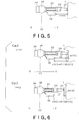
- FIG. 5 is a diagram illustrating the positional relationship between the distance detector 38 and the radioactive waste body 1 in step S11. As illustrated in the figure, in a case where it is assumed that there is no concavity and convexity or the like on the surface of the radioactive waste body 1, surface contamination inspection distance r becomes reference range r0.
- Baseline inspection r0 is, for example, a design value defined beforehand.
- the inspection table 10 rotates (step S12 in FIG. 4 ).
- the wiping material 31 wipes off the surface of the radioactive waste body 1.
- the movable element 35 does not move.
- the buffer material 32 expands and contracts. By this means, it is possible to press the wiping material 31 against the surface of the radioactive waste body 1 at appropriate power.
- the distance calculating unit 74 calculates surface contamination inspection distance r(t) on the basis of a distance signal from the distance detector 38 and stores it in the storing unit 75 (step S14).
- "t" indicates the time with reference to the surface contamination inspection start, that is, the rotation start of the inspection table 10.
- This dr(t) may be considered as concavo-convex information showing the concavity and convexity or the like on the surface of the radioactive waste body 1. Moreover, instead of distance r(t), gap dr(t) from reference range r0 may be stored in the storing unit 75.
- FIG. 6 is a diagram illustrating an example of the positional relationship between the distance detector 38 and the radioactive waste body 1 in step S12.
- the buffer material 32 expands and surface contamination inspection distance r(t1) becomes longer than reference range r0 by
- the buffer material 32 shrinks and surface contamination inspection distance r(t2) becomes shorter than reference range r0 by
- the driving unit 37 lowers the position of the movable element 35 in the Z axis direction by predetermined value Z1 (step S15). This operation is realized by generating a drive signal to move the movable element 35 in the Z axis direction until the position of the movable element 35 calculated by the current position calculating unit 72 becomes (X0, Y0, Z0-Z1, ⁇ 0).
- steps S12 to S14 are performed in new position (Z0-Z1) of the movable element 35.
- steps S12 to S15 are executed until the position in the Z axis direction becomes the lower limit position of the radioactive waste body 1 (step S16). As stated above, the wiping of the entire surface of the radioactive waste body 1 is completed.
- FIG. 7 is a diagram illustrating one example of surface contamination inspection distance r(t) stored in the storing unit 75.
- the time required for the movable element 35 to move in the Z axis direction is disregarded (step S15 in FIG. 4 ).
- surface contamination inspection distance r(t) at time t is stored in the storing unit 75.
- FIG. 8 is a flowchart illustrating a procedure of the dose rate inspection, which is details of step S4 in FIG. 3 .
- the inspection table 10 half-rotates (step S3 in FIG. 3 ).
- the position of this half-rotated radioactive waste body 1 is assumed to be a reference state.
- the driving unit 55 moves the movable element 53 to initial position (X'0, Y'0, Z'0, ⁇ '0) (step S31).
- initial position Y' is defined such that dose rate inspection distance d becomes reference range d0.
- FIG. 9 is a diagram illustrating the positional relationship between the collimator 51 and the radioactive waste body 1 in step S31.
- dose rate inspection distance d is reference range d0.
- control is performed such that dose rate inspection distance d is kept constant, it is possible to reduce reference range d0. As a result, it is possible to detect a radiation accurately and miniaturize the inspection device 100.
- the inspection table 10 rotates (step S32 in FIG. 8 ). While the radioactive waste body 1 goes into a 360-degree roll, the movable element 53 does not move in the X', Z' and ⁇ ' axis directions. However, the movable element 53 moves in the Y' axis direction as described below, such that dose rate inspection distance d becomes constant even in a case where there is a concavity and convexity on the surface of the radioactive waste body 1.
- the target position calculating unit 78 refers to surface contamination inspection distance r(t) ( FIG. 7 ) stored in the storing unit 75. Further, based on following Equation (2), the target position calculating unit 78 calculates target position Yt(t') of the movable element 53 (step S34).
- Target position Yt(t') is a position of the movable element 53 on the Y' axis to make dose rate inspection distance d become constant reference range d0 even in a case where there is a concavity and convexity on the surface of the radioactive waste body 1.
- Yt t ′ Y ′ 0 ⁇ dr t ′
- the drive signal generating unit 79 generates a drive signal such that position Y' of the movable element 53 becomes target position Yt(t').
- the movable element 53 moves to target position Yt(t') (step S35). It is specifically shown that dose rate inspection distance d becomes constant reference range d0 as a result of such operation.
- FIG. 10 is a diagram illustrating an example of the positional relationship between the collimator 51 and the radioactive waste body 1 in step S35.
- target position Yt(t1) of the movable element 53 is set larger than initial position Y'0 by
- dose rate inspection distance d becomes reference range d0.
- position Yt(t2) of the movable element 53 is set smaller than initial position Y'0 by
- dose rate inspection distance d becomes reference range d0.
- count rate C(t') calculated by the count rate calculating unit 76 is stored in the storing unit 75 together with position Z'(t) calculated by the current position calculating unit (step S36).
- the driving unit 55 lowers the position of the movable element 53 in the Z' axis direction by predetermined value Z1 (step S37).
- steps S32 to S36 are performed in new position Z0'-Z1 of the movable element 53.
- steps S32 to S37 are executed until the position in the Z' axis direction becomes the lower limit position of the radioactive waste body 1 (step S38).
- the count rate measurement of the entire surface of the radioactive waste body 1 is completed and the inspection table 10 stops (step S39).
- the dose rate calculating unit 80 converts count rate C(t') into dose rate R(t') by the use of a predetermined conversion scheme (step S40).
- the dose rate distribution calculating unit 81 calculates dose rate distribution R(p) of the radioactive waste body 1 (p is a position in the radioactive waste body 1) on the basis of dose rate R(t') and position Z'(t') (step S41). To be more specific, since the inspection table 10 rotates at constant speed, the dose rate distribution calculating unit 81 calculates the relationship between time t' and radiation detection target position p, from position Z'(t'). Further, the dose rate distribution calculating unit 81 converts dose rate R(t') that is the function of time t' into dose rate distribution R(p) that is the function of radiation detection target position p.
- both the surface contamination inspection and the dose rate inspection are conducted by rotating the inspection table 10 in a state where the radioactive waste body 1 is placed on the inspection table 10. Therefore, it is not necessary to move the radioactive waste body 1 from the surface contamination inspecting unit 30 to the dose rate inspecting unit 50, and it is possible to shorten the time required for the inspection.
- the second embodiment described below uses a plurality of distance detectors 38.
- FIG. 11 is an outline view of the radioactive waste body inspection device 100a according to the second embodiment.
- FIG. 12 is a system block diagram of the inspection device 100a in FIG. 11 .
- the same reference numerals are assigned to respective common components with FIG. 1 , FIG. 2 , and different points are mainly described below.
- the surface contamination inspecting unit 30 of the inspection device 100a has a plurality of distance detectors 38. Further, the controller 70 has a plurality of distance calculating unit 74 respectively corresponding to the distance detectors 38, and average distance calculating unit 82. Each of the distance calculating unit 74 calculates a plurality of surface contamination inspection distances on the basis of distance signals supplied from the plurality of distance detectors 38. Further, the average distance calculating unit 82 calculates the average value of the multiple surface contamination inspection distances. Further, when the surface contamination inspection illustrated in FIG. 4 is conducted, in step S14, the above-mentioned average value is used as surface contamination inspection distance r(t), that is, concavo-convex information. Others are similar to the first embodiment.
- the second embodiment similar to the first embodiment, it is possible to achieve miniaturization and improve the accuracy of the dose rate measurement. Further, in the second embodiment, since the plurality of distance detectors 38 are used, it is possible to accurately measure surface contamination inspection distance r(t). As a result, it is possible to further improve the accuracy of the dose rate measurement.
- FIG. 13 is a system block diagram of the radioactive waste body inspection device 100b of according to the third embodiment.
- the same reference numerals are assigned to respective common components with FIG. 2 , and different points are mainly described below.
- the surface contamination inspecting unit 30 of the inspection device 100b need not necessarily include the distance detector 38.
- the distance calculating unit 74 of the controller 70 converts the stroke (expansion and contraction information) calculated by the stroke calculating unit 71 into surface contamination inspection distance r.
- a stroke corresponds to concavo-convex information on the surface of the radioactive waste body 1. Therefore, when the surface contamination inspection illustrated in FIG. 4 is conducted, surface contamination inspection distance r based on the stroke can be used as concavo-convex information in step S14. That is, in the present embodiment, pressure output by the wiping unit sensor 33 can be used for concavo-convex information in place of the output of the distance detector 38 in the first and second embodiments.
- the distance detector 38 need not be newly installed, and it is possible to simplify the configuration of the inspection device 100b.
- the distance detector 38 and the wiping unit sensor 33 may be used together to generate concavo-convex information at higher accuracy.
- the controller 70 may further include moving average calculating unit 83.
- the moving average calculating unit 83 calculates the moving average of surface contamination inspection distance r calculated by the distance calculating unit 74. Even in a case where a signal output from the wiping unit sensor 33 includes noise caused by vibration or the like of the surface contamination inspecting unit 30, it is possible to ease the influence of the noise by using the moving average as concavo-convex information.
- the third embodiment similar to the first embodiment, it is possible to achieve miniaturization and improve the accuracy of dose rate measurement. Further, in the third embodiment, it is possible to generate concavo-convex information on the basis of the output from the wiping unit sensor 33.
- the fourth embodiment described below performs interlock such that the collimator 51 does not become too close to the radioactive waste body 1.
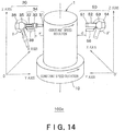
- FIG. 14 is an outline view of the radioactive waste body inspection device 100c according to the fourth embodiment.
- FIG. 15 is a system block diagram of the inspection device 100c in FIG. 14 .
- the same reference numerals are assigned to common components with FIG. 1 and FIG. 2 , and different points are mainly described below.
- the dose rate inspecting unit 50 of the inspection device 100c further includes a limit distance measurement detector 56.
- controller 70 includes a limit distance determining unit 84.
- the limit distance measurement detector 56 is a simple detector to measure the distance between the collimator 51 and the surface of the radioactive waste body 1.
- the distance detected by the limit distance measurement detector 56 is input in the limit distance determining unit 84. Further, when the above-mentioned distance becomes equal to or less than a predetermined value, the limit distance determining unit 84 generates a measurement stop signal and supplies it to the drive signal generating unit 79.
- This predetermined value is a threshold to operate interlock.
- the drive signal generating unit 79 controls the driving unit 55 such that the collimator 51 gets away from the radioactive waste body 1.
- the fourth embodiment similar to the first embodiment, it is possible to achieve miniaturization and improve the accuracy of dose rate measurement. Further, in the fourth embodiment, since the limit distance measurement detector 56 is installed, it is possible to prevent that the collimator 51 becomes too close to the radioactive waste body 1.
- At least part of the controller 70 described in the above-mentioned embodiments may be formed with hardware or software.
- a program that realizes the function of at least part of the controller 70 may be contained in a recording medium such as a flexible disk and a CD-ROM, read by a computer and executed.
- the recording medium is not limited to the detachable one such as a magnetic disk and an optical disc, and may be a fixed-type recording medium such as a hard disk device and a memory. may be a fixed-type recording medium such as a hard disk device and a memory.
- the program that realizes the function of at least part of the controller 70 may be distributed through a communication line such as the Internet (including wireless communication). Further, the program may be distributed via a wired line or wireless line such as the Internet while it is encrypted, modulated or compressed, or may be contained in a recording medium and distributed.
- a communication line such as the Internet (including wireless communication).
- the program may be distributed via a wired line or wireless line such as the Internet while it is encrypted, modulated or compressed, or may be contained in a recording medium and distributed.
Landscapes
- Physics & Mathematics (AREA)
- Health & Medical Sciences (AREA)
- Life Sciences & Earth Sciences (AREA)
- General Physics & Mathematics (AREA)
- High Energy & Nuclear Physics (AREA)
- Molecular Biology (AREA)
- Spectroscopy & Molecular Physics (AREA)
- Measurement Of Radiation (AREA)
Description
- Embodiments described herein relate generally to an inspection device of a radioactive waste body and an inspection method of the radioactive waste body.
- Generally, before a radioactive waste body is housed and transported, it is necessary to conduct a surface contamination inspection or dose rate inspection of the radioactive waste body and confirm whether the state of the waste body is within a predetermined standard. These inspections are often conducted in independent procedures and devices. For example, the surface contamination inspection of the radioactive waste is conducted using a surface contamination inspection device (which is also called a "wiping device" or a "smear device"), and, afterward, the dose rate inspection is conducted using a surface rate inspection device different from the surface contamination inspection device.
- JPH 06308245 discloses apparatus to prevent the reduction of the measurement precision and measurement efficiency and prevent the damage of a device main body.
-
WO 00/42447 -
-
FIG. 1 is an outline view of a radioactive wastebody inspection device 100 according to the first embodiment; -
FIG. 2 is a system block diagram of theinspection device 100 inFIG. 1 ; -
FIG. 3 is a flowchart illustrating a schematic procedure of inspection of aradioactive waste body 1 by the use of theinspection device 100 inFIG. 1 ; -
FIG. 4 is a flowchart illustrating a procedure of a surface contamination inspection; -
FIG. 5 is a diagram illustrating the positional relationship between adistance detector 38 and theradioactive waste body 1 in step S11; -
FIG. 6 is a diagram illustrating an example of the positional relationship between thedistance detector 38 and theradioactive waste body 1 in step S12; -
FIG. 7 is a diagram illustrating one example of surface contamination inspection distance r(t) stored in astoring unit 75; -
FIG. 8 is a flowchart illustrating a procedure of a dose rate inspection; -
FIG. 9 is a diagram illustrating the positional relationship between acollimator 51 and theradioactive waste body 1 in step S31; -
FIG. 10 is a diagram illustrating an example of the positional relationship between thecollimator 51 and theradioactive waste body 1 in step S35; -
FIG. 11 is an outline view of a radioactive wastebody inspection device 100a according to the second embodiment; -
FIG. 12 is a system block diagram of theinspection device 100a inFIG. 11 ; -
FIG. 13 is a system block diagram of a radioactive wastebody inspection device 100b according to the third embodiment; -
FIG. 14 is an outline view of an radioactive wastebody inspection device 100c according to the fourth embodiment; and -
FIG. 15 is a system block diagram of theinspection device 100c inFIG. 13 . - A radioactive waste body inspection device according to an embodiment includes a surface contamination inspecting unit configured to conduct a surface contamination inspection of a radioactive waste body while acquiring concavo-convex information on the radioactive waste body, and a dose rate inspecting unit configured to conduct a dose rate inspection of the radioactive waste body in consideration of the concavo-convex information.
- In the following, embodiments according to the present invention are described in detail with reference to the drawings.
-
FIG. 1 is an outline view of the radioactive waste body inspection device 100 (which is simply referred to as "inspection device" below) according to the first embodiment. Moreover,FIG. 2 is a system block diagram of theinspection device 100 inFIG. 1 . Theinspection device 100 is used in, for example, an acceptance factory of radioactive waste bodies, and includes an inspection table 10, a surfacecontamination inspecting unit 30, a doserate inspecting unit 50 and a controller 70 (which is not illustrated inFIG. 1 ). - The
radioactive waste body 1 is placed on the inspection table 10. The inspection table 10 has a driving unit (which is not illustrated) controlled by thecontroller 70, and this driving unit rotates the inspection table 10 at a constant speed. By this means, theradioactive waste body 1 placed on the inspection table 10 rotates at the constant speed. Although there is no specific limitation in the cross-sectional shape of the inspection table 10, the present embodiment illustrates an example in which it has a circular shape. In a case where the inspection table 10 has a circular shape, a vertical line passing the center of the inspection table 10 is referred to as "central line of the inspection table 10". - In the present embodiment, it is assumed to examine the
radioactive waste body 1 of a cylindrical shape such as a drum in which a low-level radioactive waste is filled. However, theradioactive waste body 1 has a concavity and convexity or deformation on the surface due to a manufacturing error or the like, and may not have a complete cylindrical shape. Moreover, although it is desirable to place theradioactive waste body 1 such that its center accurately locates on the central line of the inspection table 10, it may slightly shift from the central line. When the position of theradioactive waste body 1 shifts from the central line of the inspection table 10, from a surfacecontamination inspecting unit 30 and the doserate inspecting unit 50, it appears that there is a concavity and convexity on theradioactive waste body 1. - According to the present embodiment, even in this case, it is possible to accurately conduct a dose rate examination. In the following, information on the above-mentioned concavity and convexity, deformation and shift from the central line is collectively referred to as "concavo-convex information on the
radioactive waste body 1". - The surface
contamination inspecting unit 30 conducts a surface contamination inspection by wiping off the surface (for example, side surface) of theradioactive waste body 1 placed on the inspection table 10 at appropriate press power. Further, the surfacecontamination inspecting unit 30 generates concavo-convex information on theradioactive waste body 1 at the time of the surface contamination inspection. - As a specific configuration example, the surface
contamination inspecting unit 30 includes awiping material 31, abuffer material 32, awiping unit sensor 33, a movable element (first movable element) 35, aposition sensor 36, a driving unit (not illustrated) 37 and adistance detector 38. - The
wiping material 31 is, for example, a paper filter. Dirt and dust attached to the surface are wiped off by rotating and moving theradioactive waste body 1 in a state where thewiping material 31 is pressed against the surface of theradioactive waste body 1. Thewiping material 31 is collected after the wiping ends, and the surface contamination density is acquired by measuring the radiation dose of thewiping material 31. - The
buffer material 32 is, for example, a spring. Thebuffer material 32 presses thewiping material 31 against the surface of theradioactive waste body 1 at appropriate power by performing expansion and contradiction according to the surface of theradioactive waste body 1. For example, thebuffer material 32 expands in a case where the wiping target position in theradioactive waste body 1 dents, and thebuffer material 32 shrinks in a case where it bulges. - The
wiping unit sensor 33 detects a pressure at which thebuffer material 32 presses thewiping material 31 against theradioactive waste body 1, and supplies a signal indicating this pressure to thecontroller 70. The detected pressure corresponds to the expansion and contraction (stroke) of thebuffer material 32. - The
wiping material 31, thebuffer material 32 and thewiping unit sensor 33, which are described above, form awiping unit 34. - The
movable element 35 moves thewiping unit 34 in four axis directions of X, Y, Z and θ. As an example, origin O of the X, Y and Z axes is set to an arbitrary point. Further, the Y axis is a direction from origin O to the central line of the inspection table 10 in the horizontal plane. The X axis is a direction orthogonal to the Y axis in the horizontal plane. The Z axis is a vertical direction. Moreover, the θ axis is a rotation direction in the vertical plane including themovable element 35 and the central line of the inspection table 10, for example, thewiping unit 34 faces theradioactive waste body 1 when θ is 0 degrees, and thewiping unit 34 faces downward when θ is 270 degrees. Here, in a case where theradioactive waste body 1 has a cylindrical shape, themovable element 35 only has to be movable at least in the Z axis direction. - The
position sensor 36 detects each position on the X, Y, Z and θ axes (which is written as "position (X, Y, Z, θ) below) of themovable element 35, and supplies a position signal indicating this position to thecontroller 70. - The
driving unit 37 drives themovable element 35 according to a control signal from thecontroller 70 and moves themovable element 35 to s predetermined position at an appropriate speed. - The
distance detector 38 is, for example, a laser or ultrasonic non-contact detector. Thedistance detector 38 only has to move in synchronization with themovable element 35, and is fixed to the side of the movable element 35 (themovable element 35 in the example ofFIG. 1 ) by thebuffer material 32. Thedistance detector 38 detects distance r between the front edge of thedistance detector 38 and the wiping target position on the surface of the radioactive waste body 1 (which is referred to as "surface contamination inspection distance r" below), and supplies a distance signal indicating this surface contamination inspection distance r to thecontroller 70. In a case where there is a concavity and convexity on the surface of theradioactive waste body 1, surface contamination inspection distance r is not constant but is a value depending on the wiping target position on the surface of theradioactive waste body 1. - One of the features of the present embodiment is that the dose
rate inspecting unit 50 conducts a dose rate inspection using surface contamination inspection distance r as concavo-convex information in consideration of surface contamination inspection distance r. By this means, it is possible to improve the accuracy of the dose rate inspection. - Subsequently, the dose
rate inspecting unit 50 is continuously described. The doserate inspecting unit 50 is set in a position different from the surfacecontamination inspecting unit 30, that is, in a symmetrical position to the surfacecontamination inspecting unit 30 about the central line of the inspection table 10 in the example ofFIG. 1 . - The dose
rate inspecting unit 50 conducts a dose rate inspection of theradioactive waste body 1 placed on the inspection table 10 in consideration of concavo-convex information acquired by the surfacecontamination inspecting unit 30. To be more specific, even in a case where there is a concavity and convexity on the surface of theradioactive waste body 1 or theradioactive waste body 1 is placed while shifting from the center of the inspection table 10, by considering the concavo-convex information, the doserate inspecting unit 50 detects a radiation ray from theradioactive waste body 1 in a substantially constant distance from the surface of theradioactive waste body 1. - As a specific configuration example, the dose
rate inspecting unit 50 includes thecollimator 51, aradiation detector 52, a movable element (second movable element) 53, aposition sensor 54 and a driving unit 55 (not illustrated inFIG. 1 ). - The
collimator 51 is attached to the front edge of theradiation detector 52 and limits the detection range of radiation. - The radiation detection object position in the
radioactive waste body 1 is defined by thecollimator 51. - The
radiation detector 52 detects radiation from the radiation detection object position and supplies a count signal indicating the count rate of the detected radiation to thecontroller 70. Here, thecollimator 51 does not contact the radiation detection object position of theradioactive waste body 1 and is separated by distance d (which is referred to as "dose rate inspection distance d" below). By keeping dose rate inspection distance d constant as described later, theradiation detector 52 can detect the radiation accurately. - The
movable element 53 moves thecollimator 51 and theradiation detector 52 in four axis directions of X', Y', Z' and θ'. As an example, origin O' of the X', Y' and Z' axes are positions symmetrical to origin O of the X, Y and Z axes about the central line of the inspection table 10. Further, the X' axis is a direction parallel to the X axis and faces the same direction as the X axis. Moreover, the Y' axis is a direction from origin O' in the horizontal plane to the central line of the inspection table 10, in other words, it is parallel to the Y axis and faces a direction opposite to the Y axis. Further, the Z' axis is a vertical direction. Moreover, the θ' axis is a rotation direction in the vertical plane including themovable element 53 and the central line of the inspection table 10. - In a case where the
radioactive waste body 1 has a cylindrical shape, although themovable element 53 only has to be movable in the Z' axis direction, themovable element 53 is movable also in the Y' axis direction in order to keep dose rate inspection distance d constant. - In the present embodiment, the
movable element 53 moves thecollimator 51 and theradiation detector 52 such that dose rate inspection distance d between thecollimator 51 and the radiation detection object position becomes constant, in other words, the distance between theradiation detector 52 and the radiation detection object position becomes constant. - The
position sensor 54 and the drivingunit 55 are substantially similar to theposition sensor 36 and the drivingunit 37 of the surfacecontamination inspecting unit 30 respectively, and therefore explanation thereof is omitted. - The
controller 70 includesstroke calculating unit 71, currentposition calculating unit 72, drivesignal generating unit 73,distance calculating unit 74 and the storingunit 75 for surface contamination inspection. - The
stroke calculating unit 71 calculates the stroke (expansion and contraction) of thebuffer material 32 on the basis of the signal supplied from thewiping unit sensor 33. The calculated stroke is supplied to the drivesignal generating unit 73. The wipingunit 34 can monitor the power pressed against theradioactive waste body 1 on the basis of the stroke. Moreover, the calculated stroke may be stored in the storingunit 75. - The current
position calculating unit 72 calculates position (X, Y, Z, θ) of themovable element 53 on the basis of the position signal supplied from theposition sensor 36. The calculated position is optionally subjected to error correction and supplied to the drive signal generating unit. Moreover, the calculated position may be stored in the storingunit 75. - The drive
signal generating unit 73 generates a drive signal to control the drivingunit 37 on the basis of the stroke of thebuffer material 32 and position (X, Y, Z, θ) of themovable element 35. The drivingunit 37 drives themovable element 35 on the basis of this drive signal. For example, the drivesignal generating unit 73 drives the drivingunit 37 and controls the position of themovable element 35 to an appropriate position such that the power of the wipingunit 34 pressed against theradioactive waste body 1 does not become large excessively. - The
distance calculating unit 74 calculates surface contamination inspection distance r on the basis of the distance signal supplied from thedistance detector 38 and is stored in the storingunit 75. Actually, surface contamination inspection distance r is a function of time t with reference to the start time of the surface contamination inspection (that is, the rotation movement start time of the radioactive waste body 1). Therefore, the surface contamination inspection distance as concavo-convex information is written as r(t). - Moreover, the
controller 70 includes countrate calculating unit 76, currentposition calculating unit 77, targetposition calculating unit 78, drivesignal generating unit 79, doserate calculating unit 80 and dose ratedistribution calculating unit 81 for dose rate inspection. The storingunit 75 storing concavo-convex information is used for the dose rate inspection too. - The count
rate calculating unit 76 calculates count rate C on the basis of the count signal supplied from theradiation detector 52. Count rate C is stored in the storingunit 75 as function C(t') of time t' with reference to the dose check beginning. - The current
position calculating unit 77 calculates position (X', Y', Z', θ') of themovable element 53 on the basis of the position signal supplied from theposition sensor 54. At least position Z' of the calculated position is stored in the storingunit 75 as function Z'(t') of time t'. Moreover, position (X', Y', Z', θ') is supplied to the drivesignal generating unit 79. - The target
position calculating unit 78 generates a target position control signal indicating target position Yt(t') of position Y' of themovable element 53 on the basis of surface contamination inspection distance r(t) stored in the storingunit 75. This target position Yt(t') is a distance to keep dose rate inspection distance d constant. The target position control signal is supplied to the drivesignal generating unit 79. - The drive
signal generating unit 79 generates a drive signal to control the drivingunit 55, on the basis of position (X', Y', Z', θ') of themovable element 53 and the target position control signal. The drivingunit 55 drives themovable element 53 on the basis of this drive signal. - The dose
rate calculating unit 80 converts count rate C(t') stored in the storingunit 75 into dose rate R(t') by the use of a predetermined conversion scheme. - The dose rate
distribution calculating unit 81 calculates dose rate distribution on the basis of dose rate R(t') and position Z'(t') stored in the storingunit 75. As the dose rate distribution, for example, dose rate R(p) in arbitrary position p of theradioactive waste body 1 is calculated. - Here, the
controller 70 is, for example, a computer, and each unit is realized by executing a predetermined examination program in a processor. -
FIG. 3 is a flowchart illustrating a schematic procedure of inspection of theradioactive waste body 1 using theinspection device 100 inFIG. 1 . First, theradioactive waste body 1 is placed on the inspection table 10 (step S1). - Subsequently, a surface contamination inspection by the surface
contamination inspecting unit 30 is conducted (step S2). By this surface contamination inspection, surface contamination inspection distance r(t) is stored in the storingunit 75 as concavo-convex information of theradioactive waste body 1. Details of the surface contamination inspection are specifically described later usingFIG. 4 . - When the surface contamination inspection ends, the inspection table 10 half-rotates (step S3). Then, a dose rate inspection by the dose
rate inspecting unit 50 is conducted using surface contamination inspection distance r(t) stored in the storing unit 75 (step S4). Details of the dose rate inspection are specifically described later usingFIG. 8 . - Thus, in the present embodiment, both the surface contamination inspection and the dose rate inspection are conducted while the
radioactive waste body 1 is placed on the inspection table 10, in other words, without removing theradioactive waste body 1 from the inspection table 10. Therefore, it is possible to accurately conduct the dose rate inspection in consideration of a concavity and convexity on the surface of theradioactive waste body 1, and so on. -
FIG. 4 is a flowchart illustrating a procedure of the surface contamination inspection, which is details of step S2 inFIG. 3 . - First, according to a drive signal generated by the drive
signal generating unit 73, the drivingunit 37 moves themovable element 35 to an initial position (X0, Y0, Z0, θ0) (step S11). Initial position θ0 is, for example, 0 degrees, such that the wipingunit 34 turns to the center of theradioactive waste body 1. Moreover, initial position Z0 is, for example, a position on the upper surface of theradioactive waste body 1. The position of theradioactive waste body 1 before the inspection table 10 rotates is referred to as "reference state". -
FIG. 5 is a diagram illustrating the positional relationship between thedistance detector 38 and theradioactive waste body 1 in step S11. As illustrated in the figure, in a case where it is assumed that there is no concavity and convexity or the like on the surface of theradioactive waste body 1, surface contamination inspection distance r becomes reference range r0. Baseline inspection r0 is, for example, a design value defined beforehand. - In this state, the inspection table 10 rotates (step S12 in
FIG. 4 ). By this means, the wipingmaterial 31 wipes off the surface of theradioactive waste body 1. While theradioactive waste body 1 goes into a 360-degree roll, themovable element 35 does not move. However, in a case where there is a concavity and convexity or the like on the surface of theradioactive waste body 1, thebuffer material 32 expands and contracts. By this means, it is possible to press the wipingmaterial 31 against the surface of theradioactive waste body 1 at appropriate power. - Until the time the
radioactive waste body 1 goes into a 360-degree roll and returns to the reference state ("NO" in step S13), thedistance calculating unit 74 calculates surface contamination inspection distance r(t) on the basis of a distance signal from thedistance detector 38 and stores it in the storing unit 75 (step S14). Here, "t" indicates the time with reference to the surface contamination inspection start, that is, the rotation start of the inspection table 10. Surface contamination inspection distance r(t) is expressed by following Equation (1) using gap dr(t) from reference range r0.
- This dr(t) may be considered as concavo-convex information showing the concavity and convexity or the like on the surface of the
radioactive waste body 1. Moreover, instead of distance r(t), gap dr(t) from reference range r0 may be stored in the storingunit 75. -
FIG. 6 is a diagram illustrating an example of the positional relationship between thedistance detector 38 and theradioactive waste body 1 in step S12. (a) of the figure typically illustrates a case where there is a concave portion in the wiping target position at time t=t1, to be more specific, a case where the wiping target position dents by |dr(t1)|. In this case, thebuffer material 32 expands and surface contamination inspection distance r(t1) becomes longer than reference range r0 by |dr(t1|. On the other hand, (b) of the figure typically illustrates a case where there is a convex portion in the wiping target position at time t=t2, to be more specific, a case where the wiping target position bulges by |dr(t2)|. In this case, thebuffer material 32 shrinks and surface contamination inspection distance r(t2) becomes shorter than reference range r0 by |dr(t2)|. - Afterward, when the
radioactive waste body 1 goes into a 360-degree roll and returns to the reference state ("YES" in step S13 ofFIG. 4 ), the drivingunit 37 lowers the position of themovable element 35 in the Z axis direction by predetermined value Z1 (step S15). This operation is realized by generating a drive signal to move themovable element 35 in the Z axis direction until the position of themovable element 35 calculated by the currentposition calculating unit 72 becomes (X0, Y0, Z0-Z1, θ0). - Further, processing in steps S12 to S14 is performed in new position (Z0-Z1) of the
movable element 35. The above-mentioned steps S12 to S15 are executed until the position in the Z axis direction becomes the lower limit position of the radioactive waste body 1 (step S16). As stated above, the wiping of the entire surface of theradioactive waste body 1 is completed. -
FIG. 7 is a diagram illustrating one example of surface contamination inspection distance r(t) stored in the storingunit 75. Here, inFIG. 7 , the time required for themovable element 35 to move in the Z axis direction is disregarded (step S15 inFIG. 4 ). By conducting a surface contamination inspection as illustrated in the figure, surface contamination inspection distance r(t) at time t is stored in the storingunit 75. - For example, as illustrated in
FIG. 6(a) , in the wiping target position at time t1, since there is a concave portion on the surface of theradioactive waste body 1, surface contamination inspection distance r(t1) becomes longer than reference range r0. On the other hand, as illustrated inFIG. 6(b) , in the wiping target position at time t2, since there is a convex portion on the surface of theradioactive waste body 1, surface contamination inspection distance r(t2) becomes shorter than reference range r0. - Subsequently, the dose rate inspection is described.
FIG. 8 is a flowchart illustrating a procedure of the dose rate inspection, which is details of step S4 inFIG. 3 . Here, before the dose line inspection, the inspection table 10 half-rotates (step S3 inFIG. 3 ). In the following, the position of this half-rotatedradioactive waste body 1 is assumed to be a reference state. - First, according to a drive signal generated by the drive
signal generating unit 79, the drivingunit 55 moves themovable element 53 to initial position (X'0, Y'0, Z'0, θ'0) (step S31). In a case where the X', Y', Z' and θ' axes are set as described above, the initial position is expressed by X'0=X0, Z0=Z'0 and θ'0=θ0, which corresponds to the initial position at the time of the surface contamination inspection. Moreover, initial position Y' is defined such that dose rate inspection distance d becomes reference range d0. -
FIG. 9 is a diagram illustrating the positional relationship between thecollimator 51 and theradioactive waste body 1 in step S31. As illustrated in the figure, in a case where there is no concavity and convexity or the like on the surface of theradioactive waste body 1, when themovable element 53 is in initial position Y'0, dose rate inspection distance d is reference range d0. In the present embodiment, since control is performed such that dose rate inspection distance d is kept constant, it is possible to reduce reference range d0. As a result, it is possible to detect a radiation accurately and miniaturize theinspection device 100. - In this state, the inspection table 10 rotates (step S32 in
FIG. 8 ). While theradioactive waste body 1 goes into a 360-degree roll, themovable element 53 does not move in the X', Z' and θ' axis directions. However, themovable element 53 moves in the Y' axis direction as described below, such that dose rate inspection distance d becomes constant even in a case where there is a concavity and convexity on the surface of theradioactive waste body 1. - Until the time the
radioactive waste body 1 goes into a 360-degree roll and returns to the reference state ("NO" in step S33), the targetposition calculating unit 78 refers to surface contamination inspection distance r(t) (FIG. 7 ) stored in the storingunit 75. Further, based on following Equation (2), the targetposition calculating unit 78 calculates target position Yt(t') of the movable element 53 (step S34). Target position Yt(t') is a position of themovable element 53 on the Y' axis to make dose rate inspection distance d become constant reference range d0 even in a case where there is a concavity and convexity on the surface of theradioactive waste body 1.
- Here, t' indicates the time with reference to the dose rate inspection start, that is, the rotation start of the inspection table 10 (step S32). Since the inspection table 10 rotates at a constant speed, the wiping target position at time t=T0 is equal to the radiation detection target position at time t'=T0. Therefore, t'= t is established.
- Subsequently, the drive
signal generating unit 79 generates a drive signal such that position Y' of themovable element 53 becomes target position Yt(t'). By this means, themovable element 53 moves to target position Yt(t') (step S35). It is specifically shown that dose rate inspection distance d becomes constant reference range d0 as a result of such operation. -
FIG. 10 is a diagram illustrating an example of the positional relationship between thecollimator 51 and theradioactive waste body 1 in step S35. (a) of the figure typically illustrates a case where there is a concave portion in the radiation detection target position at time t'= t1, to be more specific, a case where it dents by |dr(t1)|, which corresponds toFIG. 6(a) . In this case, target position Yt(t1) of themovable element 53 is set larger than initial position Y'0 by |dr(t1)|, and thecollimator 51 approaches theradioactive waste body 1. By this means, dose rate inspection distance d becomes reference range d0. - On the other hand,
FIG. 10(b) typically illustrates a case where there is a convex portion in the radiation detection target position at time t'=t2, more specifically a case where it dents by |dr(t2)|. In this case, position Yt(t2) of themovable element 53 is set smaller than initial position Y'0 by |dr(t2)|, and thecollimator 51 moves away from theradioactive waste body 1. By this means, dose rate inspection distance d becomes reference range d0. - By performing such processing, dose rate inspection distance d always becomes constant and it is possible to improve the measurement accuracy.
- Returning to
FIG. 8 , count rate C(t') calculated by the countrate calculating unit 76 is stored in the storingunit 75 together with position Z'(t) calculated by the current position calculating unit (step S36). - Afterward, when the
radioactive waste body 1 goes into a 360-degree roll and returns to the reference state ("YES" in step S33), the drivingunit 55 lowers the position of themovable element 53 in the Z' axis direction by predetermined value Z1 (step S37). - Further, processing in steps S32 to S36 is performed in new position Z0'-Z1 of the
movable element 53. The above-mentioned steps S32 to S37 are executed until the position in the Z' axis direction becomes the lower limit position of the radioactive waste body 1 (step S38). As stated above, the count rate measurement of the entire surface of theradioactive waste body 1 is completed and the inspection table 10 stops (step S39). - Subsequently, the dose
rate calculating unit 80 converts count rate C(t') into dose rate R(t') by the use of a predetermined conversion scheme (step S40). - Further, the dose rate
distribution calculating unit 81 calculates dose rate distribution R(p) of the radioactive waste body 1 (p is a position in the radioactive waste body 1) on the basis of dose rate R(t') and position Z'(t') (step S41). To be more specific, since the inspection table 10 rotates at constant speed, the dose ratedistribution calculating unit 81 calculates the relationship between time t' and radiation detection target position p, from position Z'(t'). Further, the dose ratedistribution calculating unit 81 converts dose rate R(t') that is the function of time t' into dose rate distribution R(p) that is the function of radiation detection target position p. - Thus, in the first embodiment, when the surface contamination inspection is conducted, concavo-convex information on the
radioactive waste body 1 is acquired. Therefore, based on this concavo-convex information, dose rate inspection distance d that is the distance between thecollimator 51 and theradioactive waste body 1 can be kept constant. Therefore, the distance between thecollimator 51 and theradioactive waste body 1 need not be lengthened, and it is possible to achieve miniaturization and improve the accuracy of the dose rate measurement. - Moreover, both the surface contamination inspection and the dose rate inspection are conducted by rotating the inspection table 10 in a state where the
radioactive waste body 1 is placed on the inspection table 10. Therefore, it is not necessary to move theradioactive waste body 1 from the surfacecontamination inspecting unit 30 to the doserate inspecting unit 50, and it is possible to shorten the time required for the inspection. - The second embodiment described below uses a plurality of
distance detectors 38. -
FIG. 11 is an outline view of the radioactive wastebody inspection device 100a according to the second embodiment. Moreover,FIG. 12 is a system block diagram of theinspection device 100a inFIG. 11 . InFIG. 11 andFIG. 12 , the same reference numerals are assigned to respective common components withFIG. 1 ,FIG. 2 , and different points are mainly described below. - The surface
contamination inspecting unit 30 of theinspection device 100a has a plurality ofdistance detectors 38. Further, thecontroller 70 has a plurality ofdistance calculating unit 74 respectively corresponding to thedistance detectors 38, and averagedistance calculating unit 82. Each of thedistance calculating unit 74 calculates a plurality of surface contamination inspection distances on the basis of distance signals supplied from the plurality ofdistance detectors 38. Further, the averagedistance calculating unit 82 calculates the average value of the multiple surface contamination inspection distances. Further, when the surface contamination inspection illustrated inFIG. 4 is conducted, in step S14, the above-mentioned average value is used as surface contamination inspection distance r(t), that is, concavo-convex information. Others are similar to the first embodiment. - Thus, even in the second embodiment, similar to the first embodiment, it is possible to achieve miniaturization and improve the accuracy of the dose rate measurement. Further, in the second embodiment, since the plurality of
distance detectors 38 are used, it is possible to accurately measure surface contamination inspection distance r(t). As a result, it is possible to further improve the accuracy of the dose rate measurement. - In the above-mentioned first and second embodiments, it is assumed to generate concavo-convex information by the use of the
distance detector 38. By contrast with this, in the third embodiment described below, concavo-convex information is generated using thewiping unit sensor 33. -
FIG. 13 is a system block diagram of the radioactive wastebody inspection device 100b of according to the third embodiment. InFIG. 13 , the same reference numerals are assigned to respective common components withFIG. 2 , and different points are mainly described below. Here, the surfacecontamination inspecting unit 30 of theinspection device 100b need not necessarily include thedistance detector 38. Further, thedistance calculating unit 74 of thecontroller 70 converts the stroke (expansion and contraction information) calculated by thestroke calculating unit 71 into surface contamination inspection distance r. - Since the
buffer material 32 expands and contracts according to a concavity and convexity on the surface of theradioactive waste body 1, a stroke corresponds to concavo-convex information on the surface of theradioactive waste body 1. Therefore, when the surface contamination inspection illustrated inFIG. 4 is conducted, surface contamination inspection distance r based on the stroke can be used as concavo-convex information in step S14. That is, in the present embodiment, pressure output by thewiping unit sensor 33 can be used for concavo-convex information in place of the output of thedistance detector 38 in the first and second embodiments. - Therefore, the
distance detector 38 need not be newly installed, and it is possible to simplify the configuration of theinspection device 100b. Alternatively, thedistance detector 38 and thewiping unit sensor 33 may be used together to generate concavo-convex information at higher accuracy. - Moreover, the
controller 70 may further include movingaverage calculating unit 83. The movingaverage calculating unit 83 calculates the moving average of surface contamination inspection distance r calculated by thedistance calculating unit 74. Even in a case where a signal output from thewiping unit sensor 33 includes noise caused by vibration or the like of the surfacecontamination inspecting unit 30, it is possible to ease the influence of the noise by using the moving average as concavo-convex information. - Thus, even in the third embodiment, similar to the first embodiment, it is possible to achieve miniaturization and improve the accuracy of dose rate measurement. Further, in the third embodiment, it is possible to generate concavo-convex information on the basis of the output from the
wiping unit sensor 33. - The fourth embodiment described below performs interlock such that the
collimator 51 does not become too close to theradioactive waste body 1. -
FIG. 14 is an outline view of the radioactive wastebody inspection device 100c according to the fourth embodiment. Moreover,FIG. 15 is a system block diagram of theinspection device 100c inFIG. 14 . InFIG. 14 andFIG. 15 , the same reference numerals are assigned to common components withFIG. 1 andFIG. 2 , and different points are mainly described below. - The dose
rate inspecting unit 50 of theinspection device 100c further includes a limitdistance measurement detector 56. - Moreover, the
controller 70 includes a limitdistance determining unit 84. - The limit
distance measurement detector 56 is a simple detector to measure the distance between thecollimator 51 and the surface of theradioactive waste body 1. The distance detected by the limitdistance measurement detector 56 is input in the limitdistance determining unit 84. Further, when the above-mentioned distance becomes equal to or less than a predetermined value, the limitdistance determining unit 84 generates a measurement stop signal and supplies it to the drivesignal generating unit 79. This predetermined value is a threshold to operate interlock. - According to the measurement stop signal, the drive
signal generating unit 79 controls the drivingunit 55 such that thecollimator 51 gets away from theradioactive waste body 1. - Thus, even in the fourth embodiment, similar to the first embodiment, it is possible to achieve miniaturization and improve the accuracy of dose rate measurement. Further, in the fourth embodiment, since the limit
distance measurement detector 56 is installed, it is possible to prevent that thecollimator 51 becomes too close to theradioactive waste body 1. - At least part of the
controller 70 described in the above-mentioned embodiments may be formed with hardware or software. In a case where it is formed with software, a program that realizes the function of at least part of thecontroller 70 may be contained in a recording medium such as a flexible disk and a CD-ROM, read by a computer and executed. The recording medium is not limited to the detachable one such as a magnetic disk and an optical disc, and may be a fixed-type recording medium such as a hard disk device and a memory. may be a fixed-type recording medium such as a hard disk device and a memory. - Moreover, the program that realizes the function of at least part of the
controller 70 may be distributed through a communication line such as the Internet (including wireless communication). Further, the program may be distributed via a wired line or wireless line such as the Internet while it is encrypted, modulated or compressed, or may be contained in a recording medium and distributed.
Claims (14)
- A radioactive waste body inspection device (100) comprising:
a surface contamination inspecting unit (30) configured to conduct a surface contamination inspection of a radioactive waste body (1) while acquiring concavo-convex information on the radioactive waste body (1), the concavo-convex information indicating deformation of the radioactive waste body (1), or shift from a central line of the radioactive waste body (1); and characterised in a dose rate inspecting unit (50) configured to conduct a dose rate inspection of the radioactive waste body (1) by detecting radiation from the radioactive waste body (1) at a substantially constant distance from a surface of the radioactive waste body (1) in consideration of the concavo-convex information. - The radioactive waste body inspection device (100) of Claim 1, wherein the surface contamination inspecting unit (30) includes:a wiping material (31) configured to wipe off a surface of the radioactive waste body (1);a buffer material (32) configured to press the wiping material (31) against the surface of the radioactive waste body (1);a first movable element (35) configured to move the wiping material (31) and the buffer material (32); anda distance detector (38) configured to move in synchronization with the first movable element (35) and detect a surface contamination inspection distance between the distance detector (38) and a wiping target position on the surface of the radioactive waste body (1), as the concavo-convex information.
- The radioactive waste body inspection device (100) of Claim 2, wherein:the surface contamination inspecting unit (30) includes a plurality of the distance detectors (38); andan average value of surface contamination inspection distances detected by the plurality of the distance detectors (38) is set as the concavo-convex information.
- The radioactive waste body inspection device (100) of Claims 2 or 3, wherein:the surface contamination inspecting unit (30) wipes off the surface of the radioactive waste body (1) while the radioactive waste body (1) moves; andthe radioactive waste body inspection device (100) includes a distance calculating unit (74) configured to calculate a relationship between a time with reference to a movement start of the radioactive waste body (1) and the surface contamination inspection distance at the time, as the concavo-convex information.
- The radioactive waste body inspection device (100) of Claim 1, wherein the surface contamination inspecting unit (30) includes:a wiping material (31) configured to wipe off a surface of the radioactive waste body (1);a buffer material (32) configured to press the wiping material (31) against the surface of the radioactive waste body (1) by expanding and contracting according to the surface of the radioactive waste body (1);a first movable element (35) configured to move the wiping material (31) and the buffer material (32); anda wiping unit sensor (33) configured to detect expansion and contraction information on the buffer material (32) that is the concavo-convex information.
- The radioactive waste body inspection device (100) of Claim 5, further comprising:a distance calculating unit (74) configured to calculate, based on the expansion and contraction information, a surface contamination inspection distance between a distance detector (38) configured to move in synchronization with the first movable element (35) and a wiping target position on the surface of the radioactive waste body (1); anda moving average calculating unit (83) configured to calculate a moving average of the surface contamination inspection distance and setting the moving average as the concavo-convex information.
- The radioactive waste body inspection device (100) of any one of Claims 1-6, wherein the dose rate inspecting unit (50) includes:a collimator (51) configured to define a radiation detection target position in the radioactive waste body (1);a radiation detector (52) configured to detect a radiation from the radiation detection target position; anda second movable element (53) configured to move the radiation detector (52) such that a distance between the radiation detector (52) and the radiation detection target position becomes substantially constant, based on the concavo-convex information.
- The radioactive waste body inspection device (100) of Claim 7, wherein:the dose rate inspecting unit (50) includes a limit distance measurement detector (56) configured to detect a distance between the collimator (51) and the radioactive waste body (1); andwhen the detected distance becomes equal to or less than a predetermined value, the dose rate inspecting unit (50) stops the dose rate inspection.
- The radioactive waste body inspection device (100) of Claims 7 or 8, further comprising:a target position calculating unit (78) configured to calculate a target position of the second movable element (53) in which the distance between the radiation detector (52) and the radiation detection target position becomes substantially constant, based on the concavo-convex information; anda drive signal generating unit (73) configured to generate a drive signal to drive the second movable element (53) based on the target position,wherein the second movable element (53) moves the collimator (51) and the radiation detector (52) based on the drive signal.
- The radioactive waste body inspection device (100) of any one of Claims 7-9, further comprising:a coefficient rate calculating unit (76) configured to calculate a count rate of the radiation detected by the radiation detector (52);a dose rate calculating unit (80) configured to convert the count rate into a dose rate; anda dose rate distribution calculating unit (81) configured to calculate dose rate distribution of the radioactive waste body (1) based on the dose rate.
- The radioactive waste body inspection device (100) of any one of Claims 1-10, further comprising an inspection table (10) on which the radioactive waste body (1) is placed, wherein:the surface contamination inspecting unit (30) conducts the surface contamination inspection in a state where the radioactive waste body (1) is placed on the inspection table (10); andthe dose rate inspecting unit (50) conducts the dose rate inspection in a state where the radioactive waste body (1) is placed on the inspection table (10).
- The radioactive waste body inspection device (100) of Claim 11, wherein the surface contamination inspecting unit (30) and the dose rate inspecting unit (50) are installed in substantially symmetrical positions about a center of the inspection table (10).
- A radioactive waste body inspection method comprising:
conducting a surface contamination inspection of a radioactive waste body (1) while acquiring concavo-convex information on the radioactive waste body (1), the concavo-convex information indicating deformation of the radioactive waste body (1), or shift from a central line of the radioactive waste body (1); and characterised in conducting a dose rate inspection of the radioactive waste body (1) by detecting radiation from the radioactive waste body (1) at a substantially constant distance from a surface of the radioactive waste body (1) in consideration of the concavo-convex information. - The radioactive waste body inspection method of Claim 13, wherein the radioactive waste body (1) is placed on an inspection table (10) to conduct the surface contamination inspection, and, afterward, the dose rate inspection is conducted without removing the radioactive waste body (1) from the inspection table (10).
Applications Claiming Priority (1)
| Application Number | Priority Date | Filing Date | Title |
|---|---|---|---|
| JP2013131941A JP6280320B2 (en) | 2013-06-24 | 2013-06-24 | Radioactive waste inspection equipment |
Publications (2)
| Publication Number | Publication Date |
|---|---|
| EP2818894A1 EP2818894A1 (en) | 2014-12-31 |
| EP2818894B1 true EP2818894B1 (en) | 2018-08-15 |
Family
ID=51022744
Family Applications (1)
| Application Number | Title | Priority Date | Filing Date |
|---|---|---|---|
| EP14173451.7A Not-in-force EP2818894B1 (en) | 2013-06-24 | 2014-06-23 | Inspection device of radioactive waste body and inspection method of radioactive waste body |
Country Status (3)
| Country | Link |
|---|---|
| US (1) | US9182499B2 (en) |
| EP (1) | EP2818894B1 (en) |
| JP (1) | JP6280320B2 (en) |
Families Citing this family (8)
| Publication number | Priority date | Publication date | Assignee | Title |
|---|---|---|---|---|
| CN104297774B (en) * | 2014-09-19 | 2017-03-22 | 武汉海王核能装备工程有限公司 | Detection device for surface dose rate of wastebin |
| JP6478754B2 (en) * | 2015-03-25 | 2019-03-06 | 三菱電機株式会社 | Radioactivity measuring device |
| JP7217911B2 (en) * | 2017-02-03 | 2023-02-06 | プラネット株式会社 | Contamination inspection system |
| CN108983275A (en) * | 2018-05-25 | 2018-12-11 | 长安大学 | A kind of trick surface α β contamination meter |
| CN111736197B (en) * | 2020-03-09 | 2023-01-06 | 上海交通大学 | Low-middle-water-level radioactive waste barrel surface dose rate detection device and application thereof |
| KR102562615B1 (en) * | 2022-09-19 | 2023-08-02 | 한전케이피에스 주식회사 | Radioactive Inspection Device For Radioactive Waste |
| CN116973964A (en) * | 2023-05-05 | 2023-10-31 | 核电运行研究(上海)有限公司 | Dose rate measurement device suitable for large-volume radioactive waste barrels of various specifications |
| CN119688669B (en) * | 2025-01-21 | 2025-11-21 | 河南省核技术应用中心 | Simulation of radionuclides with rhenium element90Sr-90Method for researching surface pollution wiping efficiency by Y |
Family Cites Families (16)
| Publication number | Priority date | Publication date | Assignee | Title |
|---|---|---|---|---|
| JPS5989275U (en) * | 1982-12-09 | 1984-06-16 | 富士電機株式会社 | Surface dose rate measuring device |
| JPS62184383A (en) * | 1986-02-08 | 1987-08-12 | Jgc Corp | Automatic inspecting device for storage drum can for radioactive waste disposal |
| JPS63151884A (en) * | 1986-12-17 | 1988-06-24 | Toshiba Corp | Method and apparatus for remotely measuring surface dosage rate |
| JPH0528536Y2 (en) * | 1988-02-17 | 1993-07-22 | ||
| JPH01260389A (en) * | 1988-04-11 | 1989-10-17 | Nippon Atom Ind Group Co Ltd | Radiation measuring apparatus |
| JP2543181B2 (en) * | 1989-04-26 | 1996-10-16 | 株式会社日立製作所 | Smear device for radioactive waste drum, smear filter paper supply device for the smear head of the smear device, and device for collecting smear filter paper from the smear head |
| JPH0572342A (en) | 1991-09-11 | 1993-03-26 | Hitachi Ltd | Measuring apparatus for density of surface contamination of radioactive waste packing drum |
| JPH06308245A (en) * | 1993-04-22 | 1994-11-04 | Toshiba Corp | Surface pollution inspection device |
| JP3273850B2 (en) * | 1994-02-10 | 2002-04-15 | アロカ株式会社 | Portable radioactive surface contamination detector |
| JP3708709B2 (en) | 1998-05-13 | 2005-10-19 | 株式会社東芝 | Radioactivity measuring device |
| EP1145044B1 (en) | 1999-01-11 | 2005-02-16 | British Nuclear Fuels PLC | Apparatus and methods for investigation of radioactive sources in a sample |
| GB2409518B (en) * | 2003-12-22 | 2006-12-27 | British Nuclear Fuels Plc | Improvements in and relating to investigations |
| JP2005195459A (en) * | 2004-01-07 | 2005-07-21 | Toshiba Corp | Article removal monitoring device |
| JP4643389B2 (en) * | 2005-08-18 | 2011-03-02 | 株式会社東芝 | Contamination wiper, decontamination method and contamination inspection method |
| JP2008304350A (en) * | 2007-06-08 | 2008-12-18 | Toshiba Corp | Surface contamination inspection device and surface contamination inspection method |
| US7931784B2 (en) * | 2008-04-30 | 2011-04-26 | Xyleco, Inc. | Processing biomass and petroleum containing materials |
-
2013
- 2013-06-24 JP JP2013131941A patent/JP6280320B2/en not_active Expired - Fee Related
-
2014
- 2014-06-23 EP EP14173451.7A patent/EP2818894B1/en not_active Not-in-force
- 2014-06-23 US US14/311,596 patent/US9182499B2/en active Active
Non-Patent Citations (1)
| Title |
|---|
| None * |
Also Published As
| Publication number | Publication date |
|---|---|
| JP6280320B2 (en) | 2018-02-14 |
| US9182499B2 (en) | 2015-11-10 |
| US20140374595A1 (en) | 2014-12-25 |
| JP2015007538A (en) | 2015-01-15 |
| EP2818894A1 (en) | 2014-12-31 |
Similar Documents
| Publication | Publication Date | Title |
|---|---|---|
| US9182499B2 (en) | Inspection device of radioactive waste body and inspection method of radioactive waste body | |
| JP6253368B2 (en) | Three-dimensional shape measuring apparatus and control method thereof | |
| US9111177B2 (en) | Position/orientation measurement apparatus, processing method therefor, and non-transitory computer-readable storage medium | |
| JP6537814B2 (en) | Method and device for automatically identifying the deepest point on the surface of an anomaly | |
| JP6388587B2 (en) | Dealing with misalignment in differential phase contrast imaging | |
| US9491448B2 (en) | Laser videogrammetry | |
| US7882723B2 (en) | Abnormality detecting method for form measuring mechanism and form measuring mechanism | |
| US11867668B2 (en) | Thickness correction for video extensometer systems and methods | |
| Petz et al. | Tactile–optical probes for three-dimensional microparts | |
| EP2360638A1 (en) | Method, system and computer program product for obtaining a point spread function using motion information | |
| KR101850320B1 (en) | Computed tomography and method of error correction | |
| CN105783769A (en) | System and method for measuring gear 3D profile based on line laser scanning | |
| CN104459534A (en) | Galvanometer motor linearity detection method and device | |
| CN104133076A (en) | Speed measurement device and method and terminal | |
| CN105051486A (en) | Shape inspection device | |
| US20200348168A1 (en) | Measurement system, correction processing apparatus, correction processing method, and computer-readable recording medium | |
| JP6982667B2 (en) | Processing systems, processing methods, programs, and storage media | |
| EP3859276A1 (en) | Positioning apparatus, recording medium, and positioning method | |
| CN105593635A (en) | Measurement method, measurement device, measurement program, and computer-readable recording medium recording measurement program | |
| JP5858873B2 (en) | Friction characteristic measuring method, measuring apparatus, and program | |
| JP2015052566A (en) | Measuring device, measuring method, and article manufacturing method | |
| Kaťuch et al. | Comparision of contact and contactless measuring methods for form evaluation | |
| WO2006082932A1 (en) | Defective particle measuring apparatus and defective particle measuring method | |
| Rashidizad et al. | Building three-dimensional scanner based on structured light technique using fringe projection pattern | |
| JP6862303B2 (en) | Optical measuring device |
Legal Events
| Date | Code | Title | Description |
|---|---|---|---|
| PUAI | Public reference made under article 153(3) epc to a published international application that has entered the european phase |
Free format text: ORIGINAL CODE: 0009012 |
|
| 17P | Request for examination filed |
Effective date: 20140623 |
|
| AK | Designated contracting states |
Kind code of ref document: A1 Designated state(s): AL AT BE BG CH CY CZ DE DK EE ES FI FR GB GR HR HU IE IS IT LI LT LU LV MC MK MT NL NO PL PT RO RS SE SI SK SM TR |
|
| AX | Request for extension of the european patent |
Extension state: BA ME |
|
| GRAP | Despatch of communication of intention to grant a patent |
Free format text: ORIGINAL CODE: EPIDOSNIGR1 |
|
| STAA | Information on the status of an ep patent application or granted ep patent |
Free format text: STATUS: GRANT OF PATENT IS INTENDED |
|
| INTG | Intention to grant announced |
Effective date: 20180226 |
|
| GRAS | Grant fee paid |
Free format text: ORIGINAL CODE: EPIDOSNIGR3 |
|
| GRAA | (expected) grant |
Free format text: ORIGINAL CODE: 0009210 |
|
| STAA | Information on the status of an ep patent application or granted ep patent |
Free format text: STATUS: THE PATENT HAS BEEN GRANTED |
|
| AK | Designated contracting states |
Kind code of ref document: B1 Designated state(s): AL AT BE BG CH CY CZ DE DK EE ES FI FR GB GR HR HU IE IS IT LI LT LU LV MC MK MT NL NO PL PT RO RS SE SI SK SM TR |
|
| REG | Reference to a national code |
Ref country code: CH Ref legal event code: EP Ref country code: GB Ref legal event code: FG4D Ref country code: AT Ref legal event code: REF Ref document number: 1030426 Country of ref document: AT Kind code of ref document: T Effective date: 20180815 |
|
| REG | Reference to a national code |
Ref country code: IE Ref legal event code: FG4D |
|
| REG | Reference to a national code |
Ref country code: DE Ref legal event code: R096 Ref document number: 602014030325 Country of ref document: DE |
|
| REG | Reference to a national code |
Ref country code: NL Ref legal event code: MP Effective date: 20180815 |
|
| REG | Reference to a national code |
Ref country code: LT Ref legal event code: MG4D |
|
| REG | Reference to a national code |
Ref country code: AT Ref legal event code: MK05 Ref document number: 1030426 Country of ref document: AT Kind code of ref document: T Effective date: 20180815 |
|
| PG25 | Lapsed in a contracting state [announced via postgrant information from national office to epo] |
Ref country code: NO Free format text: LAPSE BECAUSE OF FAILURE TO SUBMIT A TRANSLATION OF THE DESCRIPTION OR TO PAY THE FEE WITHIN THE PRESCRIBED TIME-LIMIT Effective date: 20181115 Ref country code: BG Free format text: LAPSE BECAUSE OF FAILURE TO SUBMIT A TRANSLATION OF THE DESCRIPTION OR TO PAY THE FEE WITHIN THE PRESCRIBED TIME-LIMIT Effective date: 20181115 Ref country code: AT Free format text: LAPSE BECAUSE OF FAILURE TO SUBMIT A TRANSLATION OF THE DESCRIPTION OR TO PAY THE FEE WITHIN THE PRESCRIBED TIME-LIMIT Effective date: 20180815 Ref country code: IS Free format text: LAPSE BECAUSE OF FAILURE TO SUBMIT A TRANSLATION OF THE DESCRIPTION OR TO PAY THE FEE WITHIN THE PRESCRIBED TIME-LIMIT Effective date: 20181215 Ref country code: NL Free format text: LAPSE BECAUSE OF FAILURE TO SUBMIT A TRANSLATION OF THE DESCRIPTION OR TO PAY THE FEE WITHIN THE PRESCRIBED TIME-LIMIT Effective date: 20180815 Ref country code: LT Free format text: LAPSE BECAUSE OF FAILURE TO SUBMIT A TRANSLATION OF THE DESCRIPTION OR TO PAY THE FEE WITHIN THE PRESCRIBED TIME-LIMIT Effective date: 20180815 Ref country code: GR Free format text: LAPSE BECAUSE OF FAILURE TO SUBMIT A TRANSLATION OF THE DESCRIPTION OR TO PAY THE FEE WITHIN THE PRESCRIBED TIME-LIMIT Effective date: 20181116 Ref country code: RS Free format text: LAPSE BECAUSE OF FAILURE TO SUBMIT A TRANSLATION OF THE DESCRIPTION OR TO PAY THE FEE WITHIN THE PRESCRIBED TIME-LIMIT Effective date: 20180815 Ref country code: FI Free format text: LAPSE BECAUSE OF FAILURE TO SUBMIT A TRANSLATION OF THE DESCRIPTION OR TO PAY THE FEE WITHIN THE PRESCRIBED TIME-LIMIT Effective date: 20180815 Ref country code: SE Free format text: LAPSE BECAUSE OF FAILURE TO SUBMIT A TRANSLATION OF THE DESCRIPTION OR TO PAY THE FEE WITHIN THE PRESCRIBED TIME-LIMIT Effective date: 20180815 |
|
| PG25 | Lapsed in a contracting state [announced via postgrant information from national office to epo] |
Ref country code: AL Free format text: LAPSE BECAUSE OF FAILURE TO SUBMIT A TRANSLATION OF THE DESCRIPTION OR TO PAY THE FEE WITHIN THE PRESCRIBED TIME-LIMIT Effective date: 20180815 Ref country code: HR Free format text: LAPSE BECAUSE OF FAILURE TO SUBMIT A TRANSLATION OF THE DESCRIPTION OR TO PAY THE FEE WITHIN THE PRESCRIBED TIME-LIMIT Effective date: 20180815 Ref country code: LV Free format text: LAPSE BECAUSE OF FAILURE TO SUBMIT A TRANSLATION OF THE DESCRIPTION OR TO PAY THE FEE WITHIN THE PRESCRIBED TIME-LIMIT Effective date: 20180815 |
|
| PG25 | Lapsed in a contracting state [announced via postgrant information from national office to epo] |
Ref country code: ES Free format text: LAPSE BECAUSE OF FAILURE TO SUBMIT A TRANSLATION OF THE DESCRIPTION OR TO PAY THE FEE WITHIN THE PRESCRIBED TIME-LIMIT Effective date: 20180815 Ref country code: PL Free format text: LAPSE BECAUSE OF FAILURE TO SUBMIT A TRANSLATION OF THE DESCRIPTION OR TO PAY THE FEE WITHIN THE PRESCRIBED TIME-LIMIT Effective date: 20180815 Ref country code: IT Free format text: LAPSE BECAUSE OF FAILURE TO SUBMIT A TRANSLATION OF THE DESCRIPTION OR TO PAY THE FEE WITHIN THE PRESCRIBED TIME-LIMIT Effective date: 20180815 Ref country code: RO Free format text: LAPSE BECAUSE OF FAILURE TO SUBMIT A TRANSLATION OF THE DESCRIPTION OR TO PAY THE FEE WITHIN THE PRESCRIBED TIME-LIMIT Effective date: 20180815 Ref country code: CZ Free format text: LAPSE BECAUSE OF FAILURE TO SUBMIT A TRANSLATION OF THE DESCRIPTION OR TO PAY THE FEE WITHIN THE PRESCRIBED TIME-LIMIT Effective date: 20180815 Ref country code: EE Free format text: LAPSE BECAUSE OF FAILURE TO SUBMIT A TRANSLATION OF THE DESCRIPTION OR TO PAY THE FEE WITHIN THE PRESCRIBED TIME-LIMIT Effective date: 20180815 |
|
| REG | Reference to a national code |
Ref country code: DE Ref legal event code: R097 Ref document number: 602014030325 Country of ref document: DE |
|
| PG25 | Lapsed in a contracting state [announced via postgrant information from national office to epo] |
Ref country code: SM Free format text: LAPSE BECAUSE OF FAILURE TO SUBMIT A TRANSLATION OF THE DESCRIPTION OR TO PAY THE FEE WITHIN THE PRESCRIBED TIME-LIMIT Effective date: 20180815 Ref country code: DK Free format text: LAPSE BECAUSE OF FAILURE TO SUBMIT A TRANSLATION OF THE DESCRIPTION OR TO PAY THE FEE WITHIN THE PRESCRIBED TIME-LIMIT Effective date: 20180815 Ref country code: SK Free format text: LAPSE BECAUSE OF FAILURE TO SUBMIT A TRANSLATION OF THE DESCRIPTION OR TO PAY THE FEE WITHIN THE PRESCRIBED TIME-LIMIT Effective date: 20180815 |
|
| PLBE | No opposition filed within time limit |
Free format text: ORIGINAL CODE: 0009261 |
|
| STAA | Information on the status of an ep patent application or granted ep patent |
Free format text: STATUS: NO OPPOSITION FILED WITHIN TIME LIMIT |
|
| 26N | No opposition filed |
Effective date: 20190516 |
|
| PG25 | Lapsed in a contracting state [announced via postgrant information from national office to epo] |
Ref country code: SI Free format text: LAPSE BECAUSE OF FAILURE TO SUBMIT A TRANSLATION OF THE DESCRIPTION OR TO PAY THE FEE WITHIN THE PRESCRIBED TIME-LIMIT Effective date: 20180815 |
|
| REG | Reference to a national code |
Ref country code: DE Ref legal event code: R119 Ref document number: 602014030325 Country of ref document: DE |
|
| PG25 | Lapsed in a contracting state [announced via postgrant information from national office to epo] |
Ref country code: MC Free format text: LAPSE BECAUSE OF FAILURE TO SUBMIT A TRANSLATION OF THE DESCRIPTION OR TO PAY THE FEE WITHIN THE PRESCRIBED TIME-LIMIT Effective date: 20180815 |
|
| REG | Reference to a national code |
Ref country code: CH Ref legal event code: PL |
|
| REG | Reference to a national code |
Ref country code: BE Ref legal event code: MM Effective date: 20190630 |
|
| PG25 | Lapsed in a contracting state [announced via postgrant information from national office to epo] |
Ref country code: TR Free format text: LAPSE BECAUSE OF FAILURE TO SUBMIT A TRANSLATION OF THE DESCRIPTION OR TO PAY THE FEE WITHIN THE PRESCRIBED TIME-LIMIT Effective date: 20180815 |
|
| PG25 | Lapsed in a contracting state [announced via postgrant information from national office to epo] |
Ref country code: IE Free format text: LAPSE BECAUSE OF NON-PAYMENT OF DUE FEES Effective date: 20190623 Ref country code: DE Free format text: LAPSE BECAUSE OF NON-PAYMENT OF DUE FEES Effective date: 20200101 |
|
| PG25 | Lapsed in a contracting state [announced via postgrant information from national office to epo] |
Ref country code: LI Free format text: LAPSE BECAUSE OF NON-PAYMENT OF DUE FEES Effective date: 20190630 Ref country code: LU Free format text: LAPSE BECAUSE OF NON-PAYMENT OF DUE FEES Effective date: 20190623 Ref country code: CH Free format text: LAPSE BECAUSE OF NON-PAYMENT OF DUE FEES Effective date: 20190630 Ref country code: BE Free format text: LAPSE BECAUSE OF NON-PAYMENT OF DUE FEES Effective date: 20190630 |
|
| PG25 | Lapsed in a contracting state [announced via postgrant information from national office to epo] |
Ref country code: PT Free format text: LAPSE BECAUSE OF FAILURE TO SUBMIT A TRANSLATION OF THE DESCRIPTION OR TO PAY THE FEE WITHIN THE PRESCRIBED TIME-LIMIT Effective date: 20181215 |
|
| PG25 | Lapsed in a contracting state [announced via postgrant information from national office to epo] |
Ref country code: CY Free format text: LAPSE BECAUSE OF FAILURE TO SUBMIT A TRANSLATION OF THE DESCRIPTION OR TO PAY THE FEE WITHIN THE PRESCRIBED TIME-LIMIT Effective date: 20180815 |
|
| PG25 | Lapsed in a contracting state [announced via postgrant information from national office to epo] |
Ref country code: HU Free format text: LAPSE BECAUSE OF FAILURE TO SUBMIT A TRANSLATION OF THE DESCRIPTION OR TO PAY THE FEE WITHIN THE PRESCRIBED TIME-LIMIT; INVALID AB INITIO Effective date: 20140623 Ref country code: MT Free format text: LAPSE BECAUSE OF FAILURE TO SUBMIT A TRANSLATION OF THE DESCRIPTION OR TO PAY THE FEE WITHIN THE PRESCRIBED TIME-LIMIT Effective date: 20180815 |
|
| PG25 | Lapsed in a contracting state [announced via postgrant information from national office to epo] |
Ref country code: MK Free format text: LAPSE BECAUSE OF FAILURE TO SUBMIT A TRANSLATION OF THE DESCRIPTION OR TO PAY THE FEE WITHIN THE PRESCRIBED TIME-LIMIT Effective date: 20180815 |
|
| PGFP | Annual fee paid to national office [announced via postgrant information from national office to epo] |
Ref country code: FR Payment date: 20230510 Year of fee payment: 10 |
|
| PGFP | Annual fee paid to national office [announced via postgrant information from national office to epo] |
Ref country code: GB Payment date: 20230504 Year of fee payment: 10 |
|
| GBPC | Gb: european patent ceased through non-payment of renewal fee |
Effective date: 20240623 |
|
| PG25 | Lapsed in a contracting state [announced via postgrant information from national office to epo] |
Ref country code: FR Free format text: LAPSE BECAUSE OF NON-PAYMENT OF DUE FEES Effective date: 20240630 |
|
| PG25 | Lapsed in a contracting state [announced via postgrant information from national office to epo] |
Ref country code: GB Free format text: LAPSE BECAUSE OF NON-PAYMENT OF DUE FEES Effective date: 20240623 |