EP2818839B1 - Thermoelementfühler - Google Patents
Thermoelementfühler Download PDFInfo
- Publication number
- EP2818839B1 EP2818839B1 EP14173345.1A EP14173345A EP2818839B1 EP 2818839 B1 EP2818839 B1 EP 2818839B1 EP 14173345 A EP14173345 A EP 14173345A EP 2818839 B1 EP2818839 B1 EP 2818839B1
- Authority
- EP
- European Patent Office
- Prior art keywords
- thermocouple
- coolant
- probe
- temperature
- arrangement
- Prior art date
- Legal status (The legal status is an assumption and is not a legal conclusion. Google has not performed a legal analysis and makes no representation as to the accuracy of the status listed.)
- Active
Links
Images


Classifications
-
- G—PHYSICS
- G01—MEASURING; TESTING
- G01K—MEASURING TEMPERATURE; MEASURING QUANTITY OF HEAT; THERMALLY-SENSITIVE ELEMENTS NOT OTHERWISE PROVIDED FOR
- G01K7/00—Measuring temperature based on the use of electric or magnetic elements directly sensitive to heat ; Power supply therefor, e.g. using thermoelectric elements
- G01K7/02—Measuring temperature based on the use of electric or magnetic elements directly sensitive to heat ; Power supply therefor, e.g. using thermoelectric elements using thermoelectric elements, e.g. thermocouples
-
- G—PHYSICS
- G01—MEASURING; TESTING
- G01K—MEASURING TEMPERATURE; MEASURING QUANTITY OF HEAT; THERMALLY-SENSITIVE ELEMENTS NOT OTHERWISE PROVIDED FOR
- G01K1/00—Details of thermometers not specially adapted for particular types of thermometer
- G01K1/08—Protective devices, e.g. casings
- G01K1/12—Protective devices, e.g. casings for preventing damage due to heat overloading
-
- G—PHYSICS
- G01—MEASURING; TESTING
- G01K—MEASURING TEMPERATURE; MEASURING QUANTITY OF HEAT; THERMALLY-SENSITIVE ELEMENTS NOT OTHERWISE PROVIDED FOR
- G01K1/00—Details of thermometers not specially adapted for particular types of thermometer
- G01K1/20—Compensating for effects of temperature changes other than those to be measured, e.g. changes in ambient temperature
-
- G—PHYSICS
- G01—MEASURING; TESTING
- G01K—MEASURING TEMPERATURE; MEASURING QUANTITY OF HEAT; THERMALLY-SENSITIVE ELEMENTS NOT OTHERWISE PROVIDED FOR
- G01K13/00—Thermometers specially adapted for specific purposes
- G01K13/02—Thermometers specially adapted for specific purposes for measuring temperature of moving fluids or granular materials capable of flow
-
- G—PHYSICS
- G01—MEASURING; TESTING
- G01K—MEASURING TEMPERATURE; MEASURING QUANTITY OF HEAT; THERMALLY-SENSITIVE ELEMENTS NOT OTHERWISE PROVIDED FOR
- G01K7/00—Measuring temperature based on the use of electric or magnetic elements directly sensitive to heat ; Power supply therefor, e.g. using thermoelectric elements
- G01K7/02—Measuring temperature based on the use of electric or magnetic elements directly sensitive to heat ; Power supply therefor, e.g. using thermoelectric elements using thermoelectric elements, e.g. thermocouples
- G01K7/04—Measuring temperature based on the use of electric or magnetic elements directly sensitive to heat ; Power supply therefor, e.g. using thermoelectric elements using thermoelectric elements, e.g. thermocouples the object to be measured not forming one of the thermoelectric materials
-
- G—PHYSICS
- G01—MEASURING; TESTING
- G01K—MEASURING TEMPERATURE; MEASURING QUANTITY OF HEAT; THERMALLY-SENSITIVE ELEMENTS NOT OTHERWISE PROVIDED FOR
- G01K7/00—Measuring temperature based on the use of electric or magnetic elements directly sensitive to heat ; Power supply therefor, e.g. using thermoelectric elements
- G01K7/02—Measuring temperature based on the use of electric or magnetic elements directly sensitive to heat ; Power supply therefor, e.g. using thermoelectric elements using thermoelectric elements, e.g. thermocouples
- G01K7/10—Arrangements for compensating for auxiliary variables, e.g. length of lead
-
- G—PHYSICS
- G01—MEASURING; TESTING
- G01K—MEASURING TEMPERATURE; MEASURING QUANTITY OF HEAT; THERMALLY-SENSITIVE ELEMENTS NOT OTHERWISE PROVIDED FOR
- G01K2205/00—Application of thermometers in motors, e.g. of a vehicle
Definitions
- the present invention is concerned with a cooling arrangement for a thermocouple.
- Embodiments of the invention are particularly useful in conjunction with thermocouples used to sense the temperature of high temperature gases such as, for example, the gases in an engine (for example in a jet engine).
- Thermocouples of the type described in EP0989393 , EP1014059 and/or GB 2,406,967 are used to sense the temperature in a jet turbine.
- the temperature inside a turbine is measured as knowing the temperature allows one to improve or optimise control of the engine.
- Turbine temperature is an important parameter for any engine performance optimisation system.
- the temperature inside the turbine is also monitored to make sure it does not reach the engine's so-called redline temperature at which components or materials might fail.
- the redline temperature is the maximum safe running temperature or associated speed.
- the temperatures inside the turbine stage of a jet engine are typically in excess of 1000°C.
- the continuous flow of gas to which a turbine is exposed can be at a temperature between 850°C to 1700°C. This may be above the melting point of the materials used to make for example, the turbine blades so it is necessary to cool the blades.
- Turbine blades are typically cooled by creating a cooling boundary layer between the turbine surface and the hot gases. As described in EP 2 568 115 this may be done by providing hollow turbine blades with bleed holes around the blade leading edge, and feeding air from the compressor through the blade and onto the blade surface to create a cooling boundary layer between the blade surface and the hot gases.
- thermocouples used to monitor the temperature of the gases inside the turbine need to be able to cope with the very hot temperatures.
- High temperature thermocouples are typically platinum/rhodium thermocouples. Although they can operate at temperatures of up to about 1600°C, they are more expensive than, for example, K-type thermocouples.
- K-type thermocouples are more expensive than, for example, K-type thermocouples.
- thermocouples which can operate at temperatures higher than those defined by current material limits.
- thermocouple In parallel with the drive for the increased engine temperatures associated with lean burn engines, placing the turbine temperature sensing thermocouple closer to the combustor may improve the temperature measurement but also means that the thermocouple is in a hotter location and must therefore withstand higher temperatures.
- US 3,167,956 discloses a calorimetric probe for measuring gas properties at high temperatures, particularly those in excess of 5,000° K. It provides a probe which operates in environments which are too hot for thermocouples and in which the energy or enthalpy of a gas sample passing through the probe is determined.
- US 3,453,880 also discloses a high temperature probe for determining the energy or enthalpy of a gas sample passing through the probe.
- thermocouples used to sense the temperature of high temperature gases.
- thermocouple probe arrangement as defined in claim 1 to which reference should now be made.
- the inventors have appreciated that embodiments of this arrangement may allow for improved accuracy in sensing temperature in a high temperature and hostile environment whilst allowing one to use cheaper thermocouples normally not suitable for high temperature and hostile environments, and/or to place thermocouples in hotter environments or locations.
- the thermocouple probe arrangement is used for monitoring the temperature in a jet engine.
- the temperature in jet engines has been sensed with K type thermocouples as these have been adequate for the historical operating temperatures. However, as temperatures increase K-type thermocouples become unreliable.
- thermocouples such as platinum-rhodium thermocouples which can operate at higher temperatures.
- thermocouples and other system elements used in aerospace applications must go through stringent qualifying tests (by the thermocouple manufacturer, the engine manufacturer and then the relevant aviation authority) of the thermocouple itself,
- thermocouple such as a platinum-rhodium thermocouple
- the subject invention allows one to measure higher temperatures and/or locate thermocouples in higher temperature locations with the known and already tested thermocouples.
- thermocouple probe arrangement includes a probe head portion for mounting onto the casing of a gas turbine such as a jet engine, and wherein the connectors are part of the probe head portion and are to connect the probe to a data processor outside the gas turbine.
- the cooling arrangement of the thermocouple probe arrangement includes a second outlet temperature sensor for determining the temperature of the coolant as it leaves the cooling arrangement, and the thermocouple probe arrangement includes a connector for connecting the output from the second outlet temperature sensor to the correction data processor.
- the thermocouple probe arrangement may result in improved and more accurate temperature sensing, and/or allow placement of the thermcouple probe arrangement in hotter more hostile conditions and thence closer to the point which temperature one is trying to determine. Cooling the thermocouple probe means that it can operate in a hotter environment.
- Turbine Entry Temperature TET
- TGT Turbine Gas Temperature
- EGT Exhaust Gas Temperature
- the cooling arrangement is a closed loop circuit.
- the cooling arrangement is the evaporator stage of a phase-change refrigeration system. This is a particularly efficient cooling arrangement.
- the thermocouple probe includes the pair of thermocouple wires inside a sheath or casing, and a cooling jacket around the thermocouple probe, wherein the cooling jacket includes a pair of concentric tubes defining a return coolant circuit from the end of the probe proximal the connectors, to a portion of the probe distal from the connectors, and then back to the proximal end of the probe, and wherein the portion of the thermocouple probe containing the sensing end of the thermocouple projects from the cooling jacket.
- the cooling jacket includes a pair of concentric tubes defining a return coolant circuit from the end of the probe proximal the connectors, to a portion of the probe distal from the connectors, and then back to the proximal end of the probe, and wherein the portion of the thermocouple probe containing the sensing end of the thermocouple projects from the cooling jacket.
- thermocouple probe arrangement includes two separate cooling arrangements, the first cooling arrangement being for cooling a portion of the thermocouple probe proximal the connectors, and the second cooling circuit being for cooling the first sensing end of the thermocouple.
- first cooling arrangement being for cooling a portion of the thermocouple probe proximal the connectors
- second cooling circuit being for cooling the first sensing end of the thermocouple.
- thermocouple wires are supported inside a mineral insulated cable
- the second cooling arrangement is a tube running through that mineral insulated cable.
- the cooling arrangement includes means for supplying a gas coolant at a known pressure, flow and temperature to at least a portion of the surface of the thermocouple probe.
- a gas coolant at a known pressure, flow and temperature to at least a portion of the surface of the thermocouple probe.
- the invention also provides, in a second aspect, a method for determining the temperature in a high temperature environment such as a jet engine, the method comprising: providing a thermocouple to sense the temperature at its hot junction inside the jet engine; cooling at least a portion of the thermocouple inside the jet engine, by passing a coolant through an area in thermal communication with at least a portion of the thermocouple probe inside the jet engine; monitoring the supply temperature and supply flow of coolant to the thermocouple probe; and applying a compensation factor to the temperature sensed by the thermocouple, the compensation factor being determined or calculated from the supply temperature and flow of coolant to compensate for the effect of the coolant.
- thermocouples normally not suitable for high temperature and hostile environments.
- the compensation factor may be dfetermined empirically or theoretically.
- the method includes the further step of monitoring the exit temperature of coolant from the thermocouple probe and in which the determining of the compensation factor also uses the exit temperature of coolant.
- the step of applying the compensation factor includes comparing the temperature sensed by the thermocouple, the monitored coolant temperature or temperatures and the monitored coolant flow to an empirically determined look-up table.
- Creating an accurate theoretical model of the behaviour of the thermocouple system can be complicated and require significant processing.
- the inventors have appreciated that it may be advantageous and allow for reduced or simpler processing to empirically determine the relationship between the various system parameters on a test rig and use those empirically determined values to populate a multi-dimensional look-up table.
- thermocouple sensor arrangement 1 includes a thermocouple 2 of the known construction and made of two dissimilar wires 3, 4 connected at their distal ends at a hot junction to form temperature sensing end 5.
- the two dissimilar wires are connected at their end remote from the temperature sensing end 5 to sensor terminals (not shown) and thence to sensing circuitry in the known manner described in, for example EP 1 014 059 .
- the thermocouple 2 may be, for example, one of the 684 range of thermocouples available from Weston Aerospace limited and used in Rolls-Royce Trent engines.
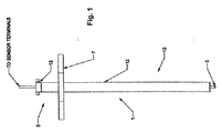
- the thermocouple sensor has a mounting flange 7 for mounting to the portion of the engine casing surrounding a hole in an engine casing (not shown) so that, in use, a stem 10 of the sensor 1 with the distal temperature sensing end 5 extends into the engine.
- a sensor head located outside the engine has sensor terminals (not shown) for connection to the sensing circuitry 10 and/or data processing arrangements.
- a cooling jacket 12 is provided around the stem 10 of the sensor and a coolant connector head 13 is provided to connect the cooling jacket 12 to a supply of coolant via a coolant inlet 14 and a coolant outlet 15.
- the cooling circuit may be the evaporator stage of a phase-change refrigeration system.
- the cooling jacket 12 could be made of a nickel based material, optimised for thermal conduction.
- the cooling jacket material preferably is of a similar material to the thermocouple.
- a nickel based cooling jacket is therefore suitable for a K type thermocouple such as those used in the Weston Aerospace 684 range of thermocouples.
- K type thermocouples have one wire of chromel (90% nickel and 10% chromium) and the other of alumel (95% nickel, 2% manganese, 2% aluminium and 1% silicon).
- the cooling jacket 12 is arranged around the known thermocouple probe 2 (see for example, GB 2,406,967 .
- the cooling jacket 12 is defined by a first intermediate tube 16 immediately adjacent and around the thermocouple probe 2, and an outer casing 17 or tube 17 surrounding the intermediate tube 16 and closed at the distal end of the probe around the distal sensing end 5 of the thermocouple.
- the temperature sensing end 5 of the thermocouple extends out from the first tube 16 and outer casing or tube 17 which form the cooling jacket 12.
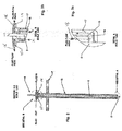
- the intermediate tube 16 and outer tube 17 define a coolant pathway 18 running from the coolant inlet 14, along the outside of the probe between the probe outer surface and the intermediate tube 16 through the distal connecting passage 19 (see Figure 3 ) into the passage between the intermediate tube 16 and outer tube 17,and thence along the outside of the intermediate tube 16 between the outside of the intermediate tube 16 and the outer cooling tube 17 to the coolant outlet 15.
- the heat energy collected by the coolant as it passes through the cooling circuit would have to be dumped after exiting the outlet 15 and before it returns to the coolant inlet 14 (in a closed loop cooling circuit).
- the heat would be dumped into a cooler zone via a second heat exchanger (not shown) before the coolant returns to the coolant inlet 14.
- the effect of the flowing coolant will significantly affect the temperature of the sensing tip. In order to accurately determine the temperature of the gas stream in which the tip is placed, it is therefore necessary to compensate or adjust for the cooling effect produced by the flow of coolant through the cooling circuit defined by the intermediate tube and outer cooling jacket.
- the magnitude or value of the cooling effect can be determined from the following coolant variables or parameters: specific heat capacity of coolant; coolant inlet and outlet temperatures as it, respectively passes, in and out of the device; mass flow rate of coolant; and pressure (especially for gaseous coolants).
- Other engine parameters and variables may have an effect and can also be used to correct or compensate for the effect of the coolant flow. These include: turbine rotor speed; pressure of gas in the turbine; and mass flow rate or velocity through the turbine of the turbine gas.
- the theoretical model relating gas temperature (i.e. actual temperature) to the temperature sensed measured gas temperature by the sensing tip and taking account of the system variables listed above is a complicated one. Rather than calculate the actual gas temperature in real time, a preferred embodiment of the invention uses a multi-dimensional look-up table, which relates actual gas temperature to the system and coolant variables.
- the look-up table values can be calculated in advance as part of the sensor system calibration or set-up. Alternatively or additionally, the values in the look-up table could be determined empirically.
- the system includes:
- the known specific heat capacity of the chosen coolant can be used to determine the rate at which heat is absorbed by the coolant as it flows from the coolant inlet 14 to the outlet 15.
- the coolant may be air, another gas or liquid, and/or a combination of these.
- the coolant would have to cope with extreme temperatures (which can reach 1700°C in a jet engine) to which the cooling system is subjected, and not change phase, or corrode the materials (nickel in the embodiments described in this application) used in the cooling circuit construction.
- the skilled man can readily identify a suitable coolant appropriate for the working conditions.
- Sensors in the turbine also sense the speed of the turbine sensors, the pressure of the turbine gas and the mass flow of gas through the turbine.
- thermocouple The value determined by each of the coolant, thermocouple and turbine sensors are fed into a data processor 23 which uses a multi-dimensional look-up table and/or algorithm to produce a value for the actual gas temperature.
- the heat absorbed by the coolant can then be determined and a model or algorithm also developed or calculated from the known laws of physics, the likely working conditions and the properties of the coolant and other system materials, properties and dimensions to then calculate a compensation factor to apply to measured temperatures to thereby determine the actual temperature of the gas flowing through the turbine.
- a model or algorithm also developed or calculated from the known laws of physics, the likely working conditions and the properties of the coolant and other system materials, properties and dimensions to then calculate a compensation factor to apply to measured temperatures to thereby determine the actual temperature of the gas flowing through the turbine.
- a first system cooling circuit 24 surrounds and cools the sensor probe stem, and a second tip cooling circuit 25 surrounds and cools the sensing tip.
- the first system cooling circuit 24 may be of a similar construction to the cooling jacket construction described above in connection with figures 1 to 3 .
- thermocouple is a thermocouple of the 684 range of Weston Aerospace thermocouples in which the two different thermocouple wires are inside a mineral insulated (MI) sheath 41 and the cavities inside the sheath and around the thermocouple wires are filed with an insulant 42.
- the tip cooling circuit is a microbore tube or pipe which runs inside the sheath and outside the thermocouple wires so that coolant flows in the direction shown in arrow X.
- the coolant tube does not completely surround the thermocouple in the embodiment shown in figures 5, 6 and 7 . It could be twisted around the tube in an alternative embodiment so that it surrounds a larger portion of the thermocouple wires.
- thermocouple surface and the hot gases flowing over it.
- This could be done via bleed holes in the outer surface of an external cooling jacket placed around the thermocouple probe where cooler bleed air at a known pressure, flow and temperature is injected into the aspirated cooling jacket aspirated into the main gas flow to provide a set amount of cooling that could be characterised (and hence produce a look-up table for converting temperatures sensed by the cooled arrangements to real temperatures by compensating for the effect of the cooling arrangement) at different hot gas and bleed air conditions.
- a further alternative could vent bleed air or liquid out of the sensing end of the probe or cooling jacket rather than having a coolant outlet in the head end of the probe and a return coolant pathway taking coolant (e.g. air) from the end of the cooling jacket near the sensing end of the probe back to an outlet at the head end of the probe.
- coolant e.g. air
- the temperature and flow rate at the coolant inlet would be sensed or otherwise determined and hence a set amount of cooling would be provided at defined conditions or operating parameters and that cooling could be taken account of.
Landscapes
- Physics & Mathematics (AREA)
- General Physics & Mathematics (AREA)
- Measuring Temperature Or Quantity Of Heat (AREA)
Claims (14)
- Thermoelementfühleranordnung (1) zum Messen der Temperatur von Hochtemperaturgasen, wie etwa den Gasen in einer Maschine, wobei der Thermoelementfühler ein Thermoelement (2) beinhaltet, das zwei Drähte (3, 4) aufweist, die an einem ersten, messenden Ende (5) zusammengefügt sind, um eine Thermoelement-Messstellenfunktion zu definieren, wobei wenigstens ein Teil der Drähte in thermischer Kommunikation mit einer Thermoelementkühlanordnung steht, wobei die Thermoelementkühlanordnung einen Einlass (14) für Kühlmittel und einen Auslass (15) für Kühlmittel hat, und bei der die Thermoelementfühleranordnung (1) einen ersten Einlasstemperatursensor (21) zum Ermitteln der Temperatur des Kühlmittels beim Eintritt in die Thermoelementkühlanordnung und einen Volumenstromsensor (20) zum Ermitteln des Volumenstroms des durch die Thermoelementfühleranordnung geführten Kühlmittels beinhaltet und bei der die Thermoelementfühleranordnung (1) Verbinder zum Verbinden der Ausgänge von dem Thermoelement, dem ersten Einlasstemperatursensor (1) und dem Volumenstromsensor (23) mit einem Korrekturdatenprozessor (23) beinhaltet, so dass der Datenprozessor die vom Thermoelement (2) gemessene Temperatur korrigieren kann, um die Wirkung der Thermoelementkühlanordnung zu berücksichtigen.
- Thermoelementfühleranordnung (1) nach Anspruch 1, die einen Fühlerkopfteil (8) zum Montieren auf dem Gehäuse einer Gasturbine, wie etwa einem Strahltriebwerk, beinhaltet und wobei die Verbinder Teil des Fühlerkopfteils sind und zum Verbinden des Fühlers mit einem Datenprozessor (23) außerhalb der Gasturbine sind.
- Thermoelementfühleranordnung (1) nach einem der vorhergehenden Ansprüche, wobei die Thermoelementkühlanordnung einen zweiten Auslasstemperatursensor (22) zum Ermitteln der Temperatur des Kühlmittels beim Verlassen der Thermoelementkühlanordnung beinhaltet und die Thermoelementfühleranordnung (1) einen Verbinder zum Verbinden des Ausgangs vom zweiten Auslasstemperatursensor (22) mit dem Korrekturdatenprozessor (23) beinhaltet.
- Thermoelementfühleranordnung (1) nach einem der vorhergehenden Ansprüche, bei der die Thermoelementkühlanordnung ein geschlossener Regelkreis ist.
- Thermoelementfühleranordnung (1) nach Anspruch 4, bei der die Thermoelementkühlanordnung die Verdampferstufe einer Kälteanlage mit Phasenübergängen ist.
- Thermoelementfühleranordnung (1) nach einem der vorhergehenden Ansprüche, das einen Thermoelementfühler (2), der ein Paar Thermoelementdrähte (3, 4) in einer Umhüllung oder einem Gehäuse beinhaltet, und einen Kühlmantel (12) um den Thermoelementfühler (2) aufweist, bei der der Kühlmantel ein Paar konzentrischer Röhren beinhaltet, die einen Rücklaufkühlmittelkreis (16, 17) vom Ende des Fühlers nahe den Verbindern (8) zu einem von den Verbindern distalen Teil des Fühlers und dann zurück zum proximalen Ende (8) des Fühlers definieren, und bei der der Teil des Thermoelementfühlers (2), der das messende Ende des Thermoelements enthält, aus dem distalen Ende des Kühlmantels (12) herausragt.
- Thermoelementfühleranordnung (1) nach einem der vorhergehenden Ansprüche, die zwei separate Thermoelementkühlanordnungen (24, 25) beinhaltet, wobei die erste Thermoelementkühlanordnung (24) zum Kühlen eines Teils des Thermoelementfühlers nahe den Verbindern ist und die zweite Kühlanordnung (25) des Thermoelements zum Kühlen des ersten, messenden Endes des Thermoelements ist.
- Thermoelementfühleranordnung (1) nach Anspruch 7, bei der die Thermoelementdrähte (3, 4) im Inneren eines mineralisolierten Kabels gelagert sind und die zweite Thermoelementkühlanordnung (25) eine durch dieses mineralisolierte Kabel verlaufende Röhre ist.
- Thermoelementfühleranordnung (1) nach Anspruch 1, bei der die Thermoelementkühlanordnung Mittel zum Zuführen eines Gaskühlmittels mit einem Druck, einem Durchfluss und einer Temperatur, die bekannt sind, zu wenigstens einem Teil der Oberfläche des Thermoelementfühlers (2) beinhaltet.
- Gekühlte Thermoelementfühleranordnung (1) nach einem der Ansprüche 1 bis 9.
- Verfahren zum Ermitteln der Temperatur in einer Hochtemperaturumgebung, wie etwa einem Strahltriebwerk, wobei das Verfahren Folgendes aufweist:Bereitstellen eines Thermoelements (2) zum Messen der Temperatur an seiner Messstelle im Inneren der Hochtemperaturumgebung;Kühlen von wenigstens einem Teil des Thermoelements (2) im Inneren der Hochtemperaturumgebung durchHindurchführen eines Kühlmittels durch einen mit wenigstens einem Teil des Thermoelements (2) im Inneren der Hochtemperaturumgebung in thermischer Kommunikation stehenden Bereich;Überwachen von Kühlmittelzufuhrtemperatur und -zufuhrfluss zum Thermoelement (2) undAnwenden eines Kompensationsfaktors auf den Thermoelementausgang, wobei der Kompensationsfaktor anhand von Kühlmittelzufuhrtemperatur und -fluss ermittelt wurde, um die Wirkung des Kühlmittels auszugleichen.
- Verfahren nach Anspruch 11, das den weiteren Schritt des Überwachens der Austrittstemperatur von Kühlmittel (22), das aus dem mit wenigstens einem Teil des Thermoelements (2) in thermischer Kommunikation stehenden Bereich austritt, beinhaltet und bei dem die Ermittlung des Anwendens des Kompensationsfaktors auch die Kühlmittelaustrittstemperatur verwendet.
- Verfahren nach einem der Ansprüche 11 und 12, bei dem die Ermittlung des Kompensationsfaktors das Vergleichen des Thermoelementausgangs, der überwachten Kühlmitteltemperatur oder -temperaturen und des überwachten Kühlmitteldurchflusses mit einer empirisch ermittelten Lookup-Tabelle beinhaltet.
- Verfahren nach einem der Ansprüche 11 bis 13, bei dem die Ermittlung des Kompensationsfaktors das Ermitteln der vom Kühlmittel absorbierten Wärme unter Verwendung der folgenden Funktion beinhaltet:

Applications Claiming Priority (1)
| Application Number | Priority Date | Filing Date | Title |
|---|---|---|---|
| GB1311174.5A GB2515483A (en) | 2013-06-24 | 2013-06-24 | Cooled Thermocouple |
Publications (3)
| Publication Number | Publication Date |
|---|---|
| EP2818839A2 EP2818839A2 (de) | 2014-12-31 |
| EP2818839A3 EP2818839A3 (de) | 2015-02-25 |
| EP2818839B1 true EP2818839B1 (de) | 2016-08-03 |
Family
ID=48998829
Family Applications (1)
| Application Number | Title | Priority Date | Filing Date |
|---|---|---|---|
| EP14173345.1A Active EP2818839B1 (de) | 2013-06-24 | 2014-06-20 | Thermoelementfühler |
Country Status (4)
| Country | Link |
|---|---|
| US (1) | US9733131B2 (de) |
| EP (1) | EP2818839B1 (de) |
| CA (1) | CA2855035C (de) |
| GB (1) | GB2515483A (de) |
Cited By (1)
| Publication number | Priority date | Publication date | Assignee | Title |
|---|---|---|---|---|
| US12152915B2 (en) | 2018-12-12 | 2024-11-26 | Weston Aerospace Limited | Probe for monitoring a moving engine element |
Families Citing this family (17)
| Publication number | Priority date | Publication date | Assignee | Title |
|---|---|---|---|---|
| NO326634B1 (no) * | 2006-09-12 | 2009-01-26 | Aker Engineering & Technology | Fremgangsmate og system for start og drift av en elektrisk drevet last |
| GB201005509D0 (en) * | 2010-03-31 | 2010-05-19 | Cambridge Entpr Ltd | Thermocouple apparatus and method |
| US9714582B2 (en) * | 2014-05-23 | 2017-07-25 | Solar Turbines Incorporated | Thermocouple with a vortex reducing probe |
| GB2540770A (en) * | 2015-07-27 | 2017-02-01 | Weston Aerospace Ltd | Cooled thermocouple |
| US20180128187A1 (en) * | 2016-11-08 | 2018-05-10 | United Technologies Corporation | Cooled cooling air safety through a temperature-monitoring line replaceable unit |
| DE102017208645A1 (de) * | 2017-05-22 | 2018-11-22 | Siemens Aktiengesellschaft | Messsondenkopf |
| CN107830944A (zh) * | 2017-11-30 | 2018-03-23 | 无锡艾立德智能科技有限公司 | 一种隔热性能稳定的无源无线温度传感器结构 |
| GB2576471A (en) * | 2018-01-09 | 2020-02-26 | Weston Aerospace Ltd | Magnetic gas turbine sensor |
| EP3576510A1 (de) * | 2018-05-29 | 2019-12-04 | Siemens Aktiengesellschaft | Kühleinrichtung für eine elektrische schaltanlage und verfahren zum betreiben einer solchen kühleinrichtung |
| US11175187B2 (en) | 2018-08-06 | 2021-11-16 | Unison Industries, Llc | Air temperature sensor having a bushing |
| US10996140B2 (en) * | 2019-03-08 | 2021-05-04 | Rolls-Royce Corporation | Gas turbine engine probes and methods of detecting an engine condition |
| EP3980738B1 (de) * | 2019-06-05 | 2023-08-02 | Compagnie Generale Des Etablissements Michelin | Temperatursensor zur verwendung in gummimischern |
| US20220163403A1 (en) * | 2020-11-25 | 2022-05-26 | Ford Global Technologies, Llc | Isolated single wire temperature sensors |
| CN113588105B (zh) * | 2021-08-31 | 2024-11-12 | 中国航发贵阳发动机设计研究所 | 高导叶型总温探针结构 |
| RU209669U1 (ru) * | 2021-11-29 | 2022-03-17 | Акционерное общество "Объединенная двигателестроительная корпорация" (АО "ОДК") | Гребенка термопар для измерения поля температур газового потока |
| CN114577351A (zh) * | 2022-03-04 | 2022-06-03 | 中国航发沈阳发动机研究所 | 一种热电偶温度传感器 |
| CN115354143B (zh) * | 2022-08-22 | 2024-03-08 | 海安天一智控设备有限公司 | 一种连续退火炉温控系统模型 |
Family Cites Families (33)
| Publication number | Priority date | Publication date | Assignee | Title |
|---|---|---|---|---|
| US2975225A (en) * | 1957-05-24 | 1961-03-14 | Curtiss Wright Corp | High temperature probe |
| US3167956A (en) * | 1963-03-12 | 1965-02-02 | Grey Jerry | Calorimetric probe |
| US3301715A (en) * | 1965-09-23 | 1967-01-31 | John E Gerrard | Thermocouple for multiple burner combustion control |
| US3453880A (en) * | 1966-02-28 | 1969-07-08 | Avco Corp | High temperature probe |
| US3535165A (en) * | 1968-03-06 | 1970-10-20 | Webb James E | Gas cooled high temperature thermocouple |
| US3769792A (en) * | 1969-09-30 | 1973-11-06 | J Grey | Control system for a turbine engine |
| US3774441A (en) * | 1971-05-06 | 1973-11-27 | Edelstahl Kombinet Hennigsdorf | Method and apparatus for the thermal analysis of metallic melts |
| GB2100003B (en) * | 1981-06-10 | 1985-02-06 | Smiths Industries Plc | Measuring temperature electrically |
| US4480930A (en) * | 1983-04-14 | 1984-11-06 | Westinghouse Electric Corp. | Pulse cooled thermocouple system for high temperature measurement especially in combustion turbines |
| US4724428A (en) * | 1986-07-07 | 1988-02-09 | Emhart Industries, Inc. | Thermocouple jacket monitor |
| US4860603A (en) * | 1988-12-05 | 1989-08-29 | Fabio Russoniello | Convection cooling probe mounting jacket |
| US5076103A (en) * | 1990-08-31 | 1991-12-31 | The United States Of America As Represented By The Administrator Of The National Aeronautics And Space Administration | Water cooled static pressure probe |
| US5184894A (en) * | 1991-02-13 | 1993-02-09 | Midwest Instrument Co., Inc. | Method of using an immersible air cooled thermocouple |
| US5104234A (en) | 1991-02-13 | 1992-04-14 | Midwest Instrument Co., Inc. | Air cooled thermocouple lance |
| US5312186A (en) * | 1992-11-04 | 1994-05-17 | The United States Of America As Represented By The United States Department Of Energy | High temperature probe |
| US5348395A (en) * | 1992-12-11 | 1994-09-20 | General Electric Company | Aspirating pyrometer with platinum thermocouple and radiation shields |
| JP2646952B2 (ja) * | 1993-02-16 | 1997-08-27 | 株式会社新潟鉄工所 | 予燃焼室式ディーゼル機関 |
| FR2771505B1 (fr) * | 1997-11-26 | 2000-06-02 | Aerospatiale | Sonde thermique pour mesurer la temperature d'un ecoulement de fluide |
| KR19990066851A (ko) | 1998-01-12 | 1999-08-16 | 카와무라 히데오 | 금속용탕 온도측정용 열전대 |
| DE59813195D1 (de) * | 1998-04-07 | 2005-12-22 | Alstom Technology Ltd Baden | Verfahren zum Messen der Temperatur von heissen Gasen mittels eines Thermoelementes sowie Messanordnung zur Durchführung des Verfahrens |
| GB2341975B (en) | 1998-09-24 | 2003-11-26 | Solartron Group Ltd | Thermocouple and method of manufacture |
| GB2344892B (en) | 1998-12-16 | 2002-11-13 | Solartron Group Ltd | Cold junction compensation for multiple thermocouples |
| FR2807145B1 (fr) * | 2000-03-30 | 2002-06-14 | Ct D Etude Et De Realisation D | Dispositif d'agencement d'un thermocouple classique par l'interieur du conduit d'alimentation air-gaz d'un bruleur a gaz pour assurer les fonctions de "securite froide" et "securite chaude" |
| US20040045813A1 (en) * | 2002-09-03 | 2004-03-11 | Seiichiro Kanno | Wafer processing apparatus, wafer stage, and wafer processing method |
| US6857776B2 (en) | 2002-12-12 | 2005-02-22 | Ametek, Inc. | Connectorized high-temperature thermocouple |
| CN2599552Y (zh) * | 2003-02-12 | 2004-01-14 | 武汉钢铁(集团)公司 | 耐火材料保护套管式抽气热电偶 |
| US7510478B2 (en) | 2003-09-11 | 2009-03-31 | Igt | Gaming apparatus software employing a script file |
| US7138901B2 (en) * | 2004-03-30 | 2006-11-21 | General Electric Company | Temperature measuring device and system and method incorporating the same |
| ITVC20040002A1 (it) * | 2004-04-09 | 2004-07-14 | Domenico Bruzzi | sonda d'estrazione, dal forno, dei gas combusti per analisi O2, CO, NOX ... (turbo-sonda O2) |
| US8250924B2 (en) * | 2008-04-22 | 2012-08-28 | Rosemount Inc. | Industrial process device utilizing piezoelectric transducer |
| US20110264084A1 (en) * | 2010-04-23 | 2011-10-27 | Concept Group, Inc. | Vacuum insulated cooling probe with heat exchanger |
| GB201010862D0 (en) * | 2010-06-29 | 2010-08-11 | Rolls Royce Plc | High temperature measurement probe |
| CH705512A1 (de) | 2011-09-12 | 2013-03-15 | Alstom Technology Ltd | Gasturbine. |
-
2013
- 2013-06-24 GB GB1311174.5A patent/GB2515483A/en not_active Withdrawn
-
2014
- 2014-06-20 EP EP14173345.1A patent/EP2818839B1/de active Active
- 2014-06-23 CA CA2855035A patent/CA2855035C/en active Active
- 2014-06-23 US US14/311,601 patent/US9733131B2/en not_active Expired - Fee Related
Cited By (1)
| Publication number | Priority date | Publication date | Assignee | Title |
|---|---|---|---|---|
| US12152915B2 (en) | 2018-12-12 | 2024-11-26 | Weston Aerospace Limited | Probe for monitoring a moving engine element |
Also Published As
| Publication number | Publication date |
|---|---|
| US20140376593A1 (en) | 2014-12-25 |
| CA2855035A1 (en) | 2014-12-24 |
| EP2818839A2 (de) | 2014-12-31 |
| EP2818839A3 (de) | 2015-02-25 |
| GB201311174D0 (en) | 2013-08-14 |
| GB2515483A (en) | 2014-12-31 |
| CA2855035C (en) | 2021-08-24 |
| US9733131B2 (en) | 2017-08-15 |
Similar Documents
| Publication | Publication Date | Title |
|---|---|---|
| CA2855035C (en) | Thermocouple | |
| EP3124929B1 (de) | Gekühltes thermoelement und temperaturmessverfahren | |
| EP2610599B1 (de) | Temperaturmessvorrichtung und Verfahren zum Aufbau davon | |
| EP2402728B1 (de) | Hochtemperatur-Messsonde | |
| JPH01299449A (ja) | 部品の表面上の熱流束および熱伝達係数の分布を測定する方法および装置 | |
| US20150049786A1 (en) | Method and system for gas temperature measurement | |
| US8104953B2 (en) | Systems and methods for determining heat transfer characteristics | |
| JP2021089276A (ja) | 温度管理システム及び温度管理方法 | |
| Kerr et al. | Optical pyrometry for gas turbine aeroengines | |
| Xue et al. | Study on the double-shielded thermocouple probe for total temperature measurement in the combustion chamber | |
| Anthony et al. | Flexible non-intrusive heat flux instrumentation for the AFRL research turbine | |
| US9335215B2 (en) | Method and system for gas temperature measurement | |
| US4440508A (en) | Detector-transducer for sensing temperatures in an engine | |
| EP3047284B1 (de) | Sensor für eine turbulente strömung bei hohen temperaturen | |
| KR200450290Y1 (ko) | 엔진 배기가스 온도 감지소자 | |
| Diller et al. | Heat flux measurements | |
| US3769792A (en) | Control system for a turbine engine | |
| GB2100003A (en) | Measuring temperature electrically | |
| RU137610U1 (ru) | Устройство измерения расхода воздуха в канале охлаждения вращающейся лопатки турбомашины | |
| RU212687U1 (ru) | Многоэлементная термопара для измерения температуры за камерой сгорания | |
| Solaro | Investigation of Sensor Faults in a Gas Turbine | |
| FIOCK et al. | The measurement of gas temperature by immersion-type instruments | |
| Gorton | Temperature measurement for aircraft-turbine-engine development: Methods are described for measuring temperature of interest to the stress analyst during development of aircraft-gas-turbine engines. Techniques for use of thermocouples on both stationary and rotating parts of the engine, and optical techniques for use on turbine parts, are described | |
| Meriç et al. | A Numerical Investigation of Total Temperature Probes Measurement Performance | |
| Wilson et al. | A robust radial traverse temperature probe for application to a gas turbine HP/IP stage |
Legal Events
| Date | Code | Title | Description |
|---|---|---|---|
| PUAI | Public reference made under article 153(3) epc to a published international application that has entered the european phase |
Free format text: ORIGINAL CODE: 0009012 |
|
| 17P | Request for examination filed |
Effective date: 20140620 |
|
| AK | Designated contracting states |
Kind code of ref document: A2 Designated state(s): AL AT BE BG CH CY CZ DE DK EE ES FI FR GB GR HR HU IE IS IT LI LT LU LV MC MK MT NL NO PL PT RO RS SE SI SK SM TR |
|
| AX | Request for extension of the european patent |
Extension state: BA ME |
|
| PUAL | Search report despatched |
Free format text: ORIGINAL CODE: 0009013 |
|
| AK | Designated contracting states |
Kind code of ref document: A3 Designated state(s): AL AT BE BG CH CY CZ DE DK EE ES FI FR GB GR HR HU IE IS IT LI LT LU LV MC MK MT NL NO PL PT RO RS SE SI SK SM TR |
|
| AX | Request for extension of the european patent |
Extension state: BA ME |
|
| RIC1 | Information provided on ipc code assigned before grant |
Ipc: G01K 1/12 20060101AFI20150120BHEP Ipc: G01K 13/02 20060101ALI20150120BHEP Ipc: G01K 7/04 20060101ALI20150120BHEP |
|
| R17P | Request for examination filed (corrected) |
Effective date: 20150804 |
|
| RBV | Designated contracting states (corrected) |
Designated state(s): AL AT BE BG CH CY CZ DE DK EE ES FI FR GB GR HR HU IE IS IT LI LT LU LV MC MK MT NL NO PL PT RO RS SE SI SK SM TR |
|
| GRAP | Despatch of communication of intention to grant a patent |
Free format text: ORIGINAL CODE: EPIDOSNIGR1 |
|
| INTG | Intention to grant announced |
Effective date: 20160218 |
|
| GRAS | Grant fee paid |
Free format text: ORIGINAL CODE: EPIDOSNIGR3 |
|
| GRAA | (expected) grant |
Free format text: ORIGINAL CODE: 0009210 |
|
| AK | Designated contracting states |
Kind code of ref document: B1 Designated state(s): AL AT BE BG CH CY CZ DE DK EE ES FI FR GB GR HR HU IE IS IT LI LT LU LV MC MK MT NL NO PL PT RO RS SE SI SK SM TR |
|
| REG | Reference to a national code |
Ref country code: GB Ref legal event code: FG4D |
|
| REG | Reference to a national code |
Ref country code: CH Ref legal event code: EP Ref country code: AT Ref legal event code: REF Ref document number: 817641 Country of ref document: AT Kind code of ref document: T Effective date: 20160815 |
|
| REG | Reference to a national code |
Ref country code: IE Ref legal event code: FG4D |
|
| REG | Reference to a national code |
Ref country code: DE Ref legal event code: R096 Ref document number: 602014002956 Country of ref document: DE |
|
| REG | Reference to a national code |
Ref country code: NL Ref legal event code: MP Effective date: 20160803 |
|
| REG | Reference to a national code |
Ref country code: LT Ref legal event code: MG4D |
|
| REG | Reference to a national code |
Ref country code: AT Ref legal event code: MK05 Ref document number: 817641 Country of ref document: AT Kind code of ref document: T Effective date: 20160803 |
|
| PG25 | Lapsed in a contracting state [announced via postgrant information from national office to epo] |
Ref country code: NO Free format text: LAPSE BECAUSE OF FAILURE TO SUBMIT A TRANSLATION OF THE DESCRIPTION OR TO PAY THE FEE WITHIN THE PRESCRIBED TIME-LIMIT Effective date: 20161103 Ref country code: NL Free format text: LAPSE BECAUSE OF FAILURE TO SUBMIT A TRANSLATION OF THE DESCRIPTION OR TO PAY THE FEE WITHIN THE PRESCRIBED TIME-LIMIT Effective date: 20160803 Ref country code: FI Free format text: LAPSE BECAUSE OF FAILURE TO SUBMIT A TRANSLATION OF THE DESCRIPTION OR TO PAY THE FEE WITHIN THE PRESCRIBED TIME-LIMIT Effective date: 20160803 Ref country code: LT Free format text: LAPSE BECAUSE OF FAILURE TO SUBMIT A TRANSLATION OF THE DESCRIPTION OR TO PAY THE FEE WITHIN THE PRESCRIBED TIME-LIMIT Effective date: 20160803 Ref country code: RS Free format text: LAPSE BECAUSE OF FAILURE TO SUBMIT A TRANSLATION OF THE DESCRIPTION OR TO PAY THE FEE WITHIN THE PRESCRIBED TIME-LIMIT Effective date: 20160803 Ref country code: IS Free format text: LAPSE BECAUSE OF FAILURE TO SUBMIT A TRANSLATION OF THE DESCRIPTION OR TO PAY THE FEE WITHIN THE PRESCRIBED TIME-LIMIT Effective date: 20161203 Ref country code: HR Free format text: LAPSE BECAUSE OF FAILURE TO SUBMIT A TRANSLATION OF THE DESCRIPTION OR TO PAY THE FEE WITHIN THE PRESCRIBED TIME-LIMIT Effective date: 20160803 |
|
| PG25 | Lapsed in a contracting state [announced via postgrant information from national office to epo] |
Ref country code: AT Free format text: LAPSE BECAUSE OF FAILURE TO SUBMIT A TRANSLATION OF THE DESCRIPTION OR TO PAY THE FEE WITHIN THE PRESCRIBED TIME-LIMIT Effective date: 20160803 Ref country code: ES Free format text: LAPSE BECAUSE OF FAILURE TO SUBMIT A TRANSLATION OF THE DESCRIPTION OR TO PAY THE FEE WITHIN THE PRESCRIBED TIME-LIMIT Effective date: 20160803 Ref country code: PL Free format text: LAPSE BECAUSE OF FAILURE TO SUBMIT A TRANSLATION OF THE DESCRIPTION OR TO PAY THE FEE WITHIN THE PRESCRIBED TIME-LIMIT Effective date: 20160803 Ref country code: GR Free format text: LAPSE BECAUSE OF FAILURE TO SUBMIT A TRANSLATION OF THE DESCRIPTION OR TO PAY THE FEE WITHIN THE PRESCRIBED TIME-LIMIT Effective date: 20161104 Ref country code: PT Free format text: LAPSE BECAUSE OF FAILURE TO SUBMIT A TRANSLATION OF THE DESCRIPTION OR TO PAY THE FEE WITHIN THE PRESCRIBED TIME-LIMIT Effective date: 20161205 Ref country code: SE Free format text: LAPSE BECAUSE OF FAILURE TO SUBMIT A TRANSLATION OF THE DESCRIPTION OR TO PAY THE FEE WITHIN THE PRESCRIBED TIME-LIMIT Effective date: 20160803 Ref country code: LV Free format text: LAPSE BECAUSE OF FAILURE TO SUBMIT A TRANSLATION OF THE DESCRIPTION OR TO PAY THE FEE WITHIN THE PRESCRIBED TIME-LIMIT Effective date: 20160803 |
|
| PG25 | Lapsed in a contracting state [announced via postgrant information from national office to epo] |
Ref country code: EE Free format text: LAPSE BECAUSE OF FAILURE TO SUBMIT A TRANSLATION OF THE DESCRIPTION OR TO PAY THE FEE WITHIN THE PRESCRIBED TIME-LIMIT Effective date: 20160803 Ref country code: RO Free format text: LAPSE BECAUSE OF FAILURE TO SUBMIT A TRANSLATION OF THE DESCRIPTION OR TO PAY THE FEE WITHIN THE PRESCRIBED TIME-LIMIT Effective date: 20160803 |
|
| REG | Reference to a national code |
Ref country code: DE Ref legal event code: R097 Ref document number: 602014002956 Country of ref document: DE |
|
| REG | Reference to a national code |
Ref country code: FR Ref legal event code: PLFP Year of fee payment: 4 |
|
| PG25 | Lapsed in a contracting state [announced via postgrant information from national office to epo] |
Ref country code: BE Free format text: LAPSE BECAUSE OF FAILURE TO SUBMIT A TRANSLATION OF THE DESCRIPTION OR TO PAY THE FEE WITHIN THE PRESCRIBED TIME-LIMIT Effective date: 20160803 Ref country code: SM Free format text: LAPSE BECAUSE OF FAILURE TO SUBMIT A TRANSLATION OF THE DESCRIPTION OR TO PAY THE FEE WITHIN THE PRESCRIBED TIME-LIMIT Effective date: 20160803 Ref country code: SK Free format text: LAPSE BECAUSE OF FAILURE TO SUBMIT A TRANSLATION OF THE DESCRIPTION OR TO PAY THE FEE WITHIN THE PRESCRIBED TIME-LIMIT Effective date: 20160803 Ref country code: DK Free format text: LAPSE BECAUSE OF FAILURE TO SUBMIT A TRANSLATION OF THE DESCRIPTION OR TO PAY THE FEE WITHIN THE PRESCRIBED TIME-LIMIT Effective date: 20160803 Ref country code: BG Free format text: LAPSE BECAUSE OF FAILURE TO SUBMIT A TRANSLATION OF THE DESCRIPTION OR TO PAY THE FEE WITHIN THE PRESCRIBED TIME-LIMIT Effective date: 20161103 Ref country code: CZ Free format text: LAPSE BECAUSE OF FAILURE TO SUBMIT A TRANSLATION OF THE DESCRIPTION OR TO PAY THE FEE WITHIN THE PRESCRIBED TIME-LIMIT Effective date: 20160803 |
|
| PLBE | No opposition filed within time limit |
Free format text: ORIGINAL CODE: 0009261 |
|
| STAA | Information on the status of an ep patent application or granted ep patent |
Free format text: STATUS: NO OPPOSITION FILED WITHIN TIME LIMIT |
|
| 26N | No opposition filed |
Effective date: 20170504 |
|
| PG25 | Lapsed in a contracting state [announced via postgrant information from national office to epo] |
Ref country code: SI Free format text: LAPSE BECAUSE OF FAILURE TO SUBMIT A TRANSLATION OF THE DESCRIPTION OR TO PAY THE FEE WITHIN THE PRESCRIBED TIME-LIMIT Effective date: 20160803 |
|
| PG25 | Lapsed in a contracting state [announced via postgrant information from national office to epo] |
Ref country code: MC Free format text: LAPSE BECAUSE OF FAILURE TO SUBMIT A TRANSLATION OF THE DESCRIPTION OR TO PAY THE FEE WITHIN THE PRESCRIBED TIME-LIMIT Effective date: 20160803 |
|
| REG | Reference to a national code |
Ref country code: CH Ref legal event code: PL |
|
| REG | Reference to a national code |
Ref country code: IE Ref legal event code: MM4A |
|
| PG25 | Lapsed in a contracting state [announced via postgrant information from national office to epo] |
Ref country code: CH Free format text: LAPSE BECAUSE OF NON-PAYMENT OF DUE FEES Effective date: 20170630 Ref country code: IE Free format text: LAPSE BECAUSE OF NON-PAYMENT OF DUE FEES Effective date: 20170620 Ref country code: LU Free format text: LAPSE BECAUSE OF NON-PAYMENT OF DUE FEES Effective date: 20170620 Ref country code: LI Free format text: LAPSE BECAUSE OF NON-PAYMENT OF DUE FEES Effective date: 20170630 |
|
| REG | Reference to a national code |
Ref country code: FR Ref legal event code: PLFP Year of fee payment: 5 |
|
| PG25 | Lapsed in a contracting state [announced via postgrant information from national office to epo] |
Ref country code: MT Free format text: LAPSE BECAUSE OF NON-PAYMENT OF DUE FEES Effective date: 20170620 |
|
| PG25 | Lapsed in a contracting state [announced via postgrant information from national office to epo] |
Ref country code: AL Free format text: LAPSE BECAUSE OF FAILURE TO SUBMIT A TRANSLATION OF THE DESCRIPTION OR TO PAY THE FEE WITHIN THE PRESCRIBED TIME-LIMIT Effective date: 20160803 |
|
| PG25 | Lapsed in a contracting state [announced via postgrant information from national office to epo] |
Ref country code: HU Free format text: LAPSE BECAUSE OF FAILURE TO SUBMIT A TRANSLATION OF THE DESCRIPTION OR TO PAY THE FEE WITHIN THE PRESCRIBED TIME-LIMIT; INVALID AB INITIO Effective date: 20140620 |
|
| PG25 | Lapsed in a contracting state [announced via postgrant information from national office to epo] |
Ref country code: CY Free format text: LAPSE BECAUSE OF FAILURE TO SUBMIT A TRANSLATION OF THE DESCRIPTION OR TO PAY THE FEE WITHIN THE PRESCRIBED TIME-LIMIT Effective date: 20160803 |
|
| PG25 | Lapsed in a contracting state [announced via postgrant information from national office to epo] |
Ref country code: MK Free format text: LAPSE BECAUSE OF FAILURE TO SUBMIT A TRANSLATION OF THE DESCRIPTION OR TO PAY THE FEE WITHIN THE PRESCRIBED TIME-LIMIT Effective date: 20160803 |
|
| PG25 | Lapsed in a contracting state [announced via postgrant information from national office to epo] |
Ref country code: TR Free format text: LAPSE BECAUSE OF FAILURE TO SUBMIT A TRANSLATION OF THE DESCRIPTION OR TO PAY THE FEE WITHIN THE PRESCRIBED TIME-LIMIT Effective date: 20160803 |
|
| P01 | Opt-out of the competence of the unified patent court (upc) registered |
Effective date: 20230530 |
|
| PGFP | Annual fee paid to national office [announced via postgrant information from national office to epo] |
Ref country code: DE Payment date: 20240617 Year of fee payment: 11 |
|
| PGFP | Annual fee paid to national office [announced via postgrant information from national office to epo] |
Ref country code: FR Payment date: 20240617 Year of fee payment: 11 |
|
| PGFP | Annual fee paid to national office [announced via postgrant information from national office to epo] |
Ref country code: IT Payment date: 20240610 Year of fee payment: 11 |
|
| PGFP | Annual fee paid to national office [announced via postgrant information from national office to epo] |
Ref country code: GB Payment date: 20250626 Year of fee payment: 12 |
|
| REG | Reference to a national code |
Ref country code: DE Ref legal event code: R119 Ref document number: 602014002956 Country of ref document: DE |
|
| PG25 | Lapsed in a contracting state [announced via postgrant information from national office to epo] |
Ref country code: DE Free format text: LAPSE BECAUSE OF NON-PAYMENT OF DUE FEES Effective date: 20260101 |
|
| PG25 | Lapsed in a contracting state [announced via postgrant information from national office to epo] |
Ref country code: IT Free format text: LAPSE BECAUSE OF NON-PAYMENT OF DUE FEES Effective date: 20250620 |
|
| PG25 | Lapsed in a contracting state [announced via postgrant information from national office to epo] |
Ref country code: FR Free format text: LAPSE BECAUSE OF NON-PAYMENT OF DUE FEES Effective date: 20250630 |