EP2818722A1 - Centrifugal pump - Google Patents
Centrifugal pump Download PDFInfo
- Publication number
- EP2818722A1 EP2818722A1 EP13173440.2A EP13173440A EP2818722A1 EP 2818722 A1 EP2818722 A1 EP 2818722A1 EP 13173440 A EP13173440 A EP 13173440A EP 2818722 A1 EP2818722 A1 EP 2818722A1
- Authority
- EP
- European Patent Office
- Prior art keywords
- ring
- centrifugal pump
- pump according
- foot part
- head part
- Prior art date
- Legal status (The legal status is an assumption and is not a legal conclusion. Google has not performed a legal analysis and makes no representation as to the accuracy of the status listed.)
- Granted
Links
Images


Classifications
-
- F—MECHANICAL ENGINEERING; LIGHTING; HEATING; WEAPONS; BLASTING
- F04—POSITIVE - DISPLACEMENT MACHINES FOR LIQUIDS; PUMPS FOR LIQUIDS OR ELASTIC FLUIDS
- F04D—NON-POSITIVE-DISPLACEMENT PUMPS
- F04D1/00—Radial-flow pumps, e.g. centrifugal pumps; Helico-centrifugal pumps
- F04D1/06—Multi-stage pumps
-
- F—MECHANICAL ENGINEERING; LIGHTING; HEATING; WEAPONS; BLASTING
- F04—POSITIVE - DISPLACEMENT MACHINES FOR LIQUIDS; PUMPS FOR LIQUIDS OR ELASTIC FLUIDS
- F04D—NON-POSITIVE-DISPLACEMENT PUMPS
- F04D17/00—Radial-flow pumps, e.g. centrifugal pumps; Helico-centrifugal pumps
- F04D17/08—Centrifugal pumps
- F04D17/10—Centrifugal pumps for compressing or evacuating
- F04D17/12—Multi-stage pumps
-
- F—MECHANICAL ENGINEERING; LIGHTING; HEATING; WEAPONS; BLASTING
- F04—POSITIVE - DISPLACEMENT MACHINES FOR LIQUIDS; PUMPS FOR LIQUIDS OR ELASTIC FLUIDS
- F04D—NON-POSITIVE-DISPLACEMENT PUMPS
- F04D29/00—Details, component parts, or accessories
- F04D29/40—Casings; Connections of working fluid
- F04D29/42—Casings; Connections of working fluid for radial or helico-centrifugal pumps
- F04D29/426—Casings; Connections of working fluid for radial or helico-centrifugal pumps especially adapted for liquid pumps
-
- F—MECHANICAL ENGINEERING; LIGHTING; HEATING; WEAPONS; BLASTING
- F04—POSITIVE - DISPLACEMENT MACHINES FOR LIQUIDS; PUMPS FOR LIQUIDS OR ELASTIC FLUIDS
- F04D—NON-POSITIVE-DISPLACEMENT PUMPS
- F04D29/00—Details, component parts, or accessories
- F04D29/60—Mounting; Assembling; Disassembling
- F04D29/62—Mounting; Assembling; Disassembling of radial or helico-centrifugal pumps
- F04D29/628—Mounting; Assembling; Disassembling of radial or helico-centrifugal pumps especially adapted for liquid pumps
Landscapes
- Engineering & Computer Science (AREA)
- Mechanical Engineering (AREA)
- General Engineering & Computer Science (AREA)
- Structures Of Non-Positive Displacement Pumps (AREA)
Abstract
Die Kreiselpumpe (1) weist mehrere Pumpenstufen auf, welche axial zwischen einem Kopfteil (4) und einem Fußteil (2) angeordnet sind. Die Pumpenstufen werden umfänglich von einem Außenmantel (3) umgeben, wobei ein axiales Ende des Außenmantels (3) am Kopfteil, das andere axiale Ende am Fußteil befestigt ist und die mechanische Verbindung zwischen Kopfteil (4) und Fußteil (2) durch den Außenmantel (3) gebildet ist.The centrifugal pump (1) has a plurality of pump stages, which are arranged axially between a head part (4) and a foot part (2). The pump stages are circumferentially surrounded by an outer shell (3), wherein one axial end of the outer shell (3) is fixed to the head part, the other axial end of the foot part and the mechanical connection between the head part (4) and foot part (2) through the outer shell ( 3) is formed.
Description
Die Erfindung betrifft eine Kreiselpumpe mit mehreren Pumpenstufen.The invention relates to a centrifugal pump with several pump stages.
Es sind mehrstufige Kreiselpumpen bekannt, bei denen zwischen einem Kopfteil und einem Fußteil mehrere Pumpenstufen, jeweils bestehend aus einem Pumpenlaufrad und einem dieses umgebenden Spiralgehäuses, angeordnet sind, wobei die Laufräder auf einer gemeinsamen Welle angeordnet sind. Dabei sind Kopfteil und Fußteil unter Einschluss der Pumpenstufen über außenliegende Zuganker in Form von Schrauben miteinander verbunden.There are multi-stage centrifugal pumps are known in which a plurality of pump stages, each consisting of a pump impeller and a surrounding spiral housing, are arranged between a head part and a foot part, wherein the wheels are arranged on a common shaft. In this case, head part and foot part, including the pump stages, are connected to one another via external tie rods in the form of screws.
Eine solche Kreiselpumpe weist typischerweise vier Schrauben auf, welche außenseitig entlang der Pumpenstufen verlaufen. Dabei sind Ausführungen bekannt, bei denen die Spiralgehäuse im Bereich der Pumpenstufen den Außenmantel bilden oder solche, bei denen eine Flüssigkeitsrückführung innerhalb des Gehäuses, typischerweise zum Fußteil erfolgt, die einen Außenmantel aufweisen, der einen Ringkanal zwischen der Außenseiten der Spiralgehäuse und dem Außenmantel bildet, über den die Förderflüssigkeit vom Kopfteil zum Fußteil oder gegebenenfalls auch umgekehrt strömt.Such a centrifugal pump typically has four screws, which extend on the outside along the pump stages. In this case, embodiments are known in which the spiral housings in the region of the pump stages form the outer jacket or those in which a liquid return takes place within the housing, typically to the foot part, which have an outer jacket which forms an annular channel between the outer sides of the spiral housing and the outer jacket, via which the delivery fluid flows from the head section to the foot section or possibly also vice versa.
Beiden Ausführungen gemeinsam ist, dass die Schrauben, mit denen Kopf- und Fußteil unter Einschluss der Pumpenstufen bzw. gegebenenfalls des diese umgebenden Außenmantels eingespannt sind, im Bereich von Kopf- und Fußteil anliegen, im Bereich der Pumpenstufen jedoch einen gewissen Abstand aufweisen. Letzteres führt dazu, dass die Temperatur der Schrauben von der der Förderflüssigkeit und damit auch der der Spiralgehäuse bzw. des Außenmantels nicht unerheblich abweichen kann, was zu thermischen Spannungen innerhalb der Kreiselpumpe führt. Solche thermischen Spannungen können zu vorzeitigem Verschleiß oder Ausfall der Pumpe führen.Both versions have in common that the screws, with which the head and foot part are clamped, including the pump stages or, where appropriate, the surrounding outer sheath, abut in the region of the head and foot, but have a certain distance in the pump stages. The latter causes the temperature of the screws of the pumped liquid and thus also that of the volute casing or the outer shell can deviate not insignificant, which leads to thermal stresses within the centrifugal pump. Such thermal stresses can lead to premature wear or failure of the pump.
Weiterhin nachteilig bei dieser Bauart ist, dass abhängig von der Anzahl der Pumpenstufen nicht nur Welle und gegebenenfalls Außenmantel in unterschiedlichen Längen bereitgestellt werden müssen, sondern dass auch die Kopf- und Fußteil verbindenden Schrauben in unterschiedlicher Länge zur Verfügung stehen müssen, um je nach Anzahl der Pumpenstufen Kopf- und Fußteil unter Einschluss der Pumpenstufen miteinander zu verbinden.Another disadvantage of this design is that depending on the number of pump stages not only shaft and possibly outer sheath must be provided in different lengths, but that the head and foot connecting screws must be available in different lengths to order depending on the number Pump steps to connect the head and foot sections, including the pump stages.
Vor diesem Hintergrund liegt der Erfindung die Aufgabe zugrunde, eine mehrstufige Kreiselpumpe so auszubilden, dass einerseits thermische Spannungen innerhalb der Pumpe vermieden, zumindest aber vermindert werden und andererseits die Bauteilvielfalt beim Aufbau von Baureihen mit unterschiedlicher Stufenzahl vermindert wird.Against this background, the invention has the object, a multi-stage centrifugal pump in such a way that on the one hand thermal stresses within the pump avoided, or at least reduced and on the other hand, the variety of components in the construction of series with different number of stages is reduced.
Diese Aufgabe wird durch eine Kreiselpumpe mit den in Anspruch 1 angegebenen Merkmalen gelöst. Vorteilhafte Ausgestaltungen der Erfindung ergeben sich aus den Unteransprüchen, der nachfolgenden Beschreibung und der Zeichnung. Dabei können gemäß der Erfindung die in den Unteransprüchen und der Beschreibung angegebenen Merkmale jeweils für sich aber auch in geeigneter Kombination die erfindungsgemäße Lösung gemäß Anspruch 1 weiter ausgestalten.This object is achieved by a centrifugal pump having the features specified in claim 1. Advantageous embodiments of the invention will become apparent from the dependent claims, the following description and the drawings. In this case, according to the invention, the features specified in the dependent claims and the description in each case but in a suitable combination, the inventive solution according to claim 1 further.
Die erfindungsgemäße Kreiselpumpe weist mehrere Pumpenstufen auf, die axial zwischen einem Kopfteil und einem Fußteil angeordnet sind. Sie weist darüber hinaus einen Außenmantel auf, der die Pumpenstufen umfänglich umgibt. Gemäß der Erfindung ist ein axiales Ende des Außenmantels am Kopfteil und das andere axiale Ende am Fußteil der Kreiselpumpe befestigt, wobei die mechanische Verbindung zwischen Kopfteil und Fußteil durch den Außenmantel gebildet ist.The centrifugal pump according to the invention has a plurality of pump stages, which are arranged axially between a head part and a foot part. It also has an outer sheath surrounding the pump stages circumferentially. According to the invention, an axial end of the outer shell on the head part and the other axial end of the foot part of Centrifugal pump attached, wherein the mechanical connection between the headboard and footboard is formed by the outer shell.
Grundgedanke der erfindungsgemäßen Lösung ist es somit, den in der Regel ohnehin vorhandenen Außenmantel zum Einspannen der Pumpenstufen zwischen Kopfteil und Fußteil zu nutzen. Der Außenmantel bildet also die mechanische Verbindung zwischen Kopfteil und Fußteil. Die axialen Enden des Außenmantels sind daher gemäß der Erfindung fest, vorzugsweise jedoch lösbar am Fußteil und am Kopfteil mittelbar oder unmittelbar befestigt. Auf diese Weise können die sonst erforderlichen Zuganker entfallen. Der Außenmantel ist, wenn dieser den ringförmigen Rückführkanal innerhalb der Kreiselpumpe bildet, stets mit dem Temperaturniveau der Förderflüssigkeit beaufschlagt, sodass Wärmespannungen weitestgehend vermieden werden, da Außenmantel und Pumpenstufen sowie Kopf- und Fußteil stets das gleiche Temperaturniveau aufweisen. Bei Ausführungen, die den Außenmantel nur zu Befestigungszwecken aufweisen, bei denen also kein Ringkanal gebildet wird, wird der Außenmantel zweckmäßigerweise an den Pumpenstufen, d. h. an der Außenseite der Spiralgehäuse anliegend ausgebildet, um nach Möglichkeit eine wärmeleitende Verbindung zu diesen herzustellen.The basic idea of the solution according to the invention is therefore to use the outer casing, which is generally present anyway, for clamping the pump stages between the head part and the foot part. The outer jacket thus forms the mechanical connection between the headboard and footboard. The axial ends of the outer shell are therefore fixed according to the invention, but preferably releasably attached to the foot and the headboard indirectly or directly. In this way, the otherwise required tie rods can be omitted. The outer jacket is, if this forms the annular return channel within the centrifugal pump, always acted upon by the temperature level of the pumped liquid, so that thermal stresses are largely avoided, since the outer jacket and pump stages and head and foot part always have the same temperature level. In embodiments which have the outer shell only for fastening purposes, in which therefore no annular channel is formed, the outer shell is expediently at the pump stages, d. H. formed on the outside of the spiral housing fitting to produce if possible, a thermally conductive connection to this.
Dabei kann in einfachster Form der Außenmantel eine zylindrische Form haben und im Kopf- und Fußteil radial eingespannt sein oder über im Wesentlichen radial angeordnete Schrauben mit dem Kopf- bzw. Fußteil fest verbunden sein. Diese Schrauben können beispielsweise durch entsprechende Bohrungen, die über den Umfang des Außenmantels an seinem Ende verteilt angeordnet sind, geführt und im Kopf bzw. Fußteil festgelegt sein.In the simplest form, the outer jacket may have a cylindrical shape and be clamped radially in the head and foot part or be firmly connected to the head or foot part via essentially radially arranged screws. These screws can for example be guided by corresponding holes which are arranged distributed over the circumference of the outer shell at its end, and fixed in the head or foot part.
Besonders vorteilhaft ist es, wenn der Außenmantel durch Eingliederung mindestens eines Ringes formschlüssig mit dem Fußteil und/oder dem Kopfteil verbunden ist. Der Vorteil einer solchen Verbindung, bei der der Formschluss durch einen zwischen den Bauteilen eingegliederten typischerweise offenen Ring gebildet ist, liegt darin, dass die Bauteile recht einfach zu montieren sind, da sie ohne den Ring durchmessermäßig so toleriert sind, dass sie ineinander steckbar sind. Erst durch Zwischenschalten dieses Ringes erfolgt die eigentliche Formschlussverbindung. Dabei ist es von besonderem Vorteil, dass durch den Ring die Kräfte über nahezu den gesamten Umfang gleichmäßig vom Fußteil bzw. Kopfteil zum Außenmantel bzw. umgekehrt eingeleitet werden. Dadurch dass die Bauteile über nahezu den gesamten Umfang aneinander anliegen, erfolgt zumindest dann, wenn diese, was in der Regel der Fall sein dürfte, aus Metall sind, eine sehr gute Wärmeübertragung zwischen den Bauteilen, sodass von einem gleichmäßigen Temperaturniveau innerhalb der Kreiselpumpe ausgegangen werden kann. Der zwischen den Bauteilen eingegliederte Ring ist vorteilhaft nicht als geschlossener Ring sondern als offener Ring ausgebildet, sodass er durch leichtes Aufweiten auch über Bauteile montiert werden kann, die größer als der Innendurchmesser des Ringes sind bzw. auch in Bauteile eingegliedert werde kann, die kleiner als der Außendurchmesser des Ringes sind, wenn dieser entsprechend zusammengedrückt wird. Anstelle des einteiligen Ringes kann auch ein mehrteiliger Ring Verwendung finden, was hinsichtlich der Montage vorteilhaft sein kann.It is particularly advantageous if the outer sheath by incorporation of at least one ring form-fitting manner with the foot part and / or the Headboard is connected. The advantage of such a connection, in which the positive connection is formed by a typically open ring incorporated between the components, is that the components are quite easy to assemble, since they are tolerated without the ring diameter that they are plugged into each other. Only by interposing this ring, the actual positive connection occurs. It is particularly advantageous that the forces over almost the entire circumference are introduced uniformly from the foot part or head part to the outer shell or vice versa by the ring. The fact that the components abut each other over almost the entire circumference, at least when they are, which is likely to be the case, made of metal, a very good heat transfer between the components, so it is assumed that a uniform temperature level within the centrifugal pump can. The integrated between the components ring is advantageously not designed as a closed ring but as an open ring, so that it can be mounted by slightly expanding also on components that are larger than the inner diameter of the ring or can be incorporated into components that smaller than the outer diameter of the ring are when it is compressed accordingly. Instead of the one-piece ring and a multi-part ring can be used, which may be advantageous in terms of assembly.
Vorzugsweise, jedoch nicht notwendigerweise, ist der rohrförmige Außenmantel aus Blech gebildet. Dieser ist an seinen axialen Enden radial aufgeweitet ausgebildet, da hierdurch eine gleichermaßen einfache wie wirkungsvolle Befestigung möglich ist, andererseits auch die Montage sehr einfach ist, wenn sich z. B. eine trichterförmige Aufnahme ergibt, die eine leichte Montage am Außenumfang der Pumpenstufen ermöglicht. Die Aufweitung kann dabei radial nach außen oder radial nach innen oder in beide Richtungen erfolgen, vorteilhaft durch plastische Formgebung, wie Rollen, Tiefziehen, Stauchen, Bördeln oder dergleichen.Preferably, but not necessarily, the tubular outer jacket is formed of sheet metal. This is formed radially widened at its axial ends, as this an equally simple and effective attachment is possible, on the other hand, the assembly is very simple when z. B. results in a funnel-shaped receptacle, which allows easy mounting on the outer circumference of the pump stages. The expansion can take place radially outward or radially inward or in both directions, advantageously by plastic Shaping, such as rolling, deep drawing, upsetting, flanging or the like.
Die Befestigung des Außenmantels im Kopfteil bzw. im Fußteil erfolgt besonders vorteilhaft, wenn am Fußteil und/oder am Kopfteil ein zumindest abschnittsweise umlaufender radial nach innen gerichteter Vorsprung vorgesehen ist. Dieser Vorsprung ist zweckmäßigerweise so gestaltet, dass das axiale, gegebenenfalls aufgeweitete, Ende des Außenmantels noch gerade hindurchführbar ist und erst nach Eingliederung des Ringes der gewünschte Formschluss, insbesondere in axialer Richtung, erfolgt. Ein solcher Vorsprung kann, wenn das Kopfteil bzw. das Fußteil aus Guss gefertigt sind, unmittelbar vorgesehen sein. Es ist jedoch auch denkbar, den Vorsprung durch ein gesondertes, ein- oder mehrteiliges, ringförmiges Bauteil zu bilden, welches am Kopf- bzw. Fußteil festgelegt wird, typischerweise schraubbefestigt wird. So kann ein solcher Vorsprung um 360° umlaufend gebildet sein, wenn er durch einen Flansch gebildet ist, der am Kopfteil oder am Fußteil typischerweise an einer axialen Stirnseite schraubbefestigt ist.The attachment of the outer shell in the head part or in the foot part is particularly advantageous if at least partially circumferential radially inwardly directed projection is provided on the foot part and / or on the head part. This projection is expediently designed so that the axial, optionally flared, end of the outer shell is still just passed and only after integration of the ring of the desired fit, in particular in the axial direction occurs. Such a projection can, if the head part or the foot part are made of cast iron, be provided directly. However, it is also conceivable to form the projection by a separate, single or multi-part, annular component which is fixed to the head or foot, is typically screwed. Thus, such a projection may be 360 ° circumferentially formed when it is formed by a flange which is screw-mounted on the head part or the foot part typically on an axial end face.
Ein solcher Flansch kann einteilig gebildet sein, jedoch auch mehrteilig. In letzterem Falle ist es vorteilhaft, wenn die einzelnen Flanschteile identisch ausgebildet sind, z. B. durch zwei identische Flanschhälften.Such a flange may be formed in one piece, but also in several parts. In the latter case, it is advantageous if the individual flange parts are identical, z. B. by two identical flange halves.
Vorteilhaft kann auch der Ring, der den Formschluss zwischen Kopfteil und Außenmantel bzw. Fußteil und Außenmantel herstellt, mehrteilig ausgebildet sein. Dann ist es zweckmäßig, den Ring so zu teilen, dass alle Teile identisch ausgebildet sind, z. B. zwei identische Ringhälften vorzusehen.Advantageously, the ring, which produces the positive connection between the head part and outer shell or foot part and outer shell, be formed in several parts. Then it is appropriate to divide the ring so that all parts are identical, z. B. to provide two identical ring halves.
Neben etwaigen Nuten zur Eingliederung von O-Ringen zwischen Außenmantel und Kopfteil bzw. Außenmantel und Fußteil weist der Außenmantel vorteilhaft an mindestens einem Ende eine umlaufende und radial nach außen offene Nut auf, welche zur Eingliederung des Ringes dient, mit welchem der Formschluss zwischen Außenmantel und Kopfteil bzw. Außenmantel und Fußteil hergestellt wird. Wenn der Außenmantel aus Blech gebildet ist, kann eine solche Nut durch eine Einformung in diesem Bereich gebildet sein.In addition to any grooves for the incorporation of O-rings between the outer shell and headboard or outer shell and foot, the outer shell advantageously at least one end of a circumferential and radially outwardly open groove, which serves for the integration of the ring, with which the positive connection between the outer shell and headboard or outer shell and footboard is made. If the outer sheath is formed from sheet metal, such a groove may be formed by a molding in this area.
Darüber hinaus weisen Kopf- bzw. Fußteil vorteilhaft ebenfalls eine umlaufende, jedoch radial nach innen offene Nut zur Aufnahme des Ringes auf, welche vorteilhaft so angeordnet ist, dass sie in Einbaulage der Nut am Ende des Außenmantels gegenüberliegt oder vom Außenmantel zum Kopfteil bzw. Fußteil hin gesehen vor dem radial aufgeweiteten Ende des Außenmantels angeordnet ist. Diese Anordnung stellt sicher, dass der darin einzugliedernde Ring das aufgeweitete Ende des Außenmantels formschlüssig innerhalb des Kopfteils bzw. Fußteils hält. Eine solche Nut ist entweder bei einem Gussteil von vornherein eingeformt, was kostengünstig ist, oder aber gegebenenfalls auch spanend hergestellt. Schließlich kann eine solche Nut auch durch Schraubbefestigen eines Flansches an einer Axialseite vom Kopf- bzw. Fußteil gebildet werden. Besonders vorteilhaft ist es, wenn am Kopfteil und/oder am Fußteil Mittel zum radialen Verschieben des Ringes vorgesehen sind. Mit solchen Mitteln ist es möglich, den bereits zwischen den Bauteilen eingegliederten Ring von einer nicht verriegelnden in eine verriegelnde Stellung zu bewegen oder umgekehrt. Dabei ist unter radialem Verschieben im Sinne der Erfindung nicht nur ein räumliches Verschieben des Ringes bzw. von Ringteilen zu verstehen, sondern insbesondere auch eine Veränderung des Durchmessers des Ringes durch Stauchen oder Aufweiten. Letzteres setzt allerdings voraus, dass der Ring zumindest offen oder mehrteilig ausgebildet ist.In addition, head and foot also advantageously have a circumferential, but radially inwardly open groove for receiving the ring, which is advantageously arranged so that it is opposite in the installed position of the groove at the end of the outer shell or from the outer shell to the headboard or footboard seen in front of the radially expanded end of the outer shell is arranged. This arrangement ensures that the ring to be incorporated therein holds the flared end of the outer shell in a form-fitting manner within the head part or foot part. Such a groove is formed either in a casting from the outset, which is inexpensive, or possibly also made by machining. Finally, such a groove can also be formed by screwing a flange to an axial side of the head or foot part. It is particularly advantageous if means for radially displacing the ring are provided on the head part and / or on the foot part. By such means it is possible to move the already incorporated between the components ring from a non-locking to a locking position or vice versa. Here, radial displacement in the sense of the invention not only a spatial displacement of the ring or ring parts to understand, but in particular a change in the diameter of the ring by upsetting or widening. The latter requires, however, that the ring is at least open or multi-part design.
Solche Mittel zum Verschieben können beispielsweise durch am Kopfteil- und/oder am Fußteil vorzugsweise radial angeordnete Gewindeschrauben gebildet sein, die von außen zugänglich sind und jeweils in einer Gewindebohrung geführt sind, die in der nach innen offenen Nut mündet. Mit solchen vergleichsweise einfachen Stellschrauben kann ein in die nach innen offene Nut eingegliederter Ring radial nach innen verschoben bzw. zusammengedrückt werden, um in die gegenüberliegende Nut des Außenmantels einzugreifen oder zumindest so weit an den Außenmantel heran zu ragen, dass die dahinter befindliche Aufweitung formschlüssig gehalten ist. Wenn, was vorteilhaft ist, der Ring als offener Federring ausgebildet ist, dann kann durch Herausdrehen dieser Gewindeschrauben eine Demontage erfolgen, da der Ring dann selbsttätig in seine Ausgangsstellung zurückfedert.Such means for shifting can be formed, for example, by threaded head screws, preferably radially arranged on the head part and / or on the foot part, which are accessible from the outside and in each case in a threaded bore are guided, which opens into the groove open inwardly. With such comparatively simple screws, a ring inserted in the inwardly open groove can be displaced or compressed radially inwards in order to engage in the opposite groove of the outer jacket or to protrude at least so far against the outer jacket that the widening behind it is held in a form-fitting manner is. If, which is advantageous, the ring is designed as an open spring ring, then disassembly can be done by unscrewing these screws, since the ring then springs back automatically to its original position.
Wenn, was vorteilhaft ist, ein offener Federring als Ring zur Formschlussverbindung zwischen Kopfteil und Außenmantel bzw. zwischen Fußteil und Außenmantel vorgesehen ist, dann kann der Ringdurchmesser allein dadurch verändert werden, dass der Abstand der Ringenden eingestellt wird. Es können also vorteilhaft Mittel zur Einstellung dieses Abstandes am Kopfteil und/oder Fußteil vorgesehen sein, um mit wenigen Handgriffen den Formschluss herzustellen und gegebenenfalls auch wieder zu lösen.If, which is advantageous, an open spring ring is provided as a ring for positive connection between the head and outer shell or between the foot and outer shell, then the ring diameter can be changed only by the fact that the distance between the ring ends is adjusted. It can therefore be advantageously provided means for adjusting this distance on the headboard and / or footboard to make the positive connection with a few simple steps and optionally also to solve again.
Gemäß einer vorteilhaften Weiterbildung der Erfindung ist ein Hilfsring vorgesehen, mit welchem der Ring in seine verriegelnde Stellung überführbar ist, wobei Mittel zum Bewegen des Hilfsrings am oder im Fußteil bzw. Kopfteil vorgesehen sind. Die Anordnung eines solchen Hilfsrings hat den Vorteil, dass der eigentliche Ring, der zur Befestigung zwischen Kopfteil und Außenmantel bzw. Fußteil und Außenmantel vorgesehen ist, nicht punktuell durch Schrauben oder ähnliche Körper belastet wird, sondern lediglich dieser Hilfsring, der im Übrigen aber kaum Kräfte aufnehmen muss. Der Hilfsring dient also ausschließlich dazu, den Ring in seine verriegelnde bzw. entriegelnde Stellung zu bringen und dort zu halten.According to an advantageous embodiment of the invention, an auxiliary ring is provided, with which the ring can be converted into its locking position, wherein means for moving the auxiliary ring are provided on or in the foot part or headboard. The arrangement of such an auxiliary ring has the advantage that the actual ring, which is provided for attachment between the head and outer shell or foot and outer sheath is not punctually loaded by screws or similar body, but only this auxiliary ring, which, however, hardly forces must record. The auxiliary ring thus serves exclusively to bring the ring into its locking or unlocking position and to hold it there.
Vorzugsweise sind am axialen Ende des Außenmantels Formschlussmittel vorgesehen, welche den Außenmantel drehfest am Fußteil bzw. am Kopfteil halten. Solche Formschlussmittel können durch eine Nut-/Federanordnung im Bereich des aufgeweiteten Teils am Außenumfang des Außenmantels sowie an der korrespondierenden Innenseite der entsprechenden Aufnahme von Kopfteil bzw. Fußteil vorgesehen sein. So können beispielsweise im aufgeweiteten Teil des Außenmantels achsparallele Ausnehmungen über den Umfang verteilt angeordnet sein, die in entsprechende Vorsprünge in der zugehörigen Aufnahme vom Kopfteil bzw. Fußteil eingreifen. Diese Bauteile sorgen für eine drehfeste Verbindung zwischen Kopfteil und Außenmantel bzw. Fußteil und Außenmantel.Preferably, interlocking means are provided at the axial end of the outer jacket, which hold the outer jacket against rotation on the foot part or on the head part. Such positive locking means can be provided by a tongue and groove arrangement in the region of the widened part on the outer circumference of the outer jacket and on the corresponding inner side of the corresponding receptacle of the head part or foot part. For example, in the widened part of the outer jacket, axially parallel recesses can be distributed over the circumference, which engage in corresponding projections in the associated receptacle from the head part or foot part. These components provide a rotationally fixed connection between the headboard and outer shell or foot and outer shell.
Die Erfindung ist nachfolgend anhand von in der Zeichnung dargestellten Ausführungsbeispielen näher erläutert. Es zeigen:
- Fig. 1
- in stark vereinfachter perspektivischer Darstellung eine Ansicht eines erfindungsgemäßen Kreiselpumpenaggregates mit unterschiedlichen Befestigungen von Kopfteil und Fußteil,
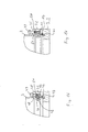
- Fig. 2
- in perspektivischer Darstellung eine Ausführung der Befestigung eines axialen Außenmantelendes am Fußteil,
- Fig. 3
- die Verbindung der
Fig. 2 in Explosionsdarstellung, - Fig. 4
- einen Längsschnitt durch die Verbindung nach
Fig. 2 , - Fig. 5
- in stark vergrößerter Darstellung die Einzelheit V in
Fig. 4 , - Fig. 6
- eine alternative Befestigung in Darstellung nach
Fig. 5 , - Fig. 7
- eine weitere Ausführung in Darstellung nach
Fig. 5 - Fig. 8
- ein weiteres Ausführungsbeispiel in Darstellung nach
Fig. 2 , - Fig. 9
- die Ausführung nach
Fig. 8 in Explosionsdarstellung, - Fig. 10
- einen Querschnitt mit drei verschiedenen Stellungen des Ringes,
- Fig. 11
- die Verbindung gemäß
Fig. 10 in entriegelter Stellung in Darstellung entsprechendFig. 5 , - Fig. 12
- ein weiteres Ausführungsbeispiel in Explosionsdarstellung entsprechend
Fig. 3 , - Fig. 13
- die Verbindung im zusammengefügten Zustand in Darstellung entsprechend
Fig. 5 , - Fig. 14
- ein anderes Ausführungsbeispiel der Befestigung des Außenmantels im Fußteil in Darstellung entsprechend
Fig. 2 , - Fig. 15
- einen Längsschnitt der Ausführung gemäß
Fig. 14 in Darstellung entsprechendFig. 4 , - Fig. 16
- die Verbindung nach den
Figuren 14 - 15 in verriegelter Stellung in Darstellung entsprechendFig. 5 , - Fig. 17
- die Verbindung nach den
Figuren 14 - 15 in entriegelter Stellung in Darstellung entsprechendFig. 5 , - Fig. 18
- ein weiteres Ausführungsbeispiel in Explosionsdarstellung entsprechend
Fig. 3 , - Fig. 19
- die Verbindung gemäß
Fig. 18 in Darstellung nachFig. 5 mit eingeführtem Werkzeug, - Fig. 20
- die Verbindung nach
Fig. 18 in verriegelter Stellung in Darstellung entsprechendFig. 5 und - Fig. 21
- die Verbindung nach
Fig. 18 in entriegelter Stellung in Darstellung entsprechendFig. 5 .
- Fig. 1
- in a greatly simplified perspective view of a view of a centrifugal pump assembly according to the invention with different fasteners of the headboard and footboard,
- Fig. 2
- a perspective view of an embodiment of the attachment of an axial outer shell end to the foot part,
- Fig. 3
- the connection of the
Fig. 2 in exploded view, - Fig. 4
- a longitudinal section through the connection after
Fig. 2 . - Fig. 5
- in a greatly enlarged view the detail V in
Fig. 4 . - Fig. 6
- an alternative attachment in representation after
Fig. 5 . - Fig. 7
- another embodiment in illustration after
Fig. 5 - Fig. 8
- a further embodiment in illustration according to
Fig. 2 . - Fig. 9
- the execution after
Fig. 8 in exploded view, - Fig. 10
- a cross section with three different positions of the ring,
- Fig. 11
- the connection according to
Fig. 10 in unlocked position in representation accordinglyFig. 5 . - Fig. 12
- a further embodiment in exploded view corresponding
Fig. 3 . - Fig. 13
- the connection in the assembled state in representation accordingly
Fig. 5 . - Fig. 14
- another embodiment of the attachment of the outer shell in the foot part in illustration accordingly
Fig. 2 . - Fig. 15
- a longitudinal section of the embodiment according to
Fig. 14 in representation accordinglyFig. 4 . - Fig. 16
- the connection to the
FIGS. 14-15 in locked position in representation accordinglyFig. 5 . - Fig. 17
- the connection to the
FIGS. 14-15 in unlocked position in representation accordinglyFig. 5 . - Fig. 18
- a further embodiment in exploded view corresponding
Fig. 3 . - Fig. 19
- the connection according to
Fig. 18 in representation afterFig. 5 with inserted tool, - Fig. 20
- the connection after
Fig. 18 in locked position in representation accordinglyFig. 5 and - Fig. 21
- the connection after
Fig. 18 in unlocked position in representation accordinglyFig. 5 ,
Bei der dargestellten Kreiselpumpe 1 handelt es sich um eine mehrstufige Inlinepumpe. Die Kreiselpumpe 1 ist zum aufrechtstehenden Betrieb bestimmt und sie weist ein Fußteil 2 auf, an das nach oben hin ein Außenmantel 3 anschließt, dessen oberes Ende von einem Kopfteil 4 aufgenommen ist, welches zugleich einen Motorstuhl für den darüber angeordneten elektrischen Antriebsmotor 5 bildet. Der Aufbau der in
Das aus Guss bestehende Fußteil 2 weist eine einstückig mit diesem ausgebildete untere Platte 6 auf, die den eigentlichen Fuß der Kreiselpumpe 1 bildet und mit der die Kreiselpumpe 1 auf dem Boden aufsteht und über in der Platte 6 befindliche Bohrungen mit dem Boden schraubbefestigt werden kann. Das Fußteil 2 hat im Übrigen die Form eines zylindrischen Rohres 7 mit vertikaler Achse, das an seinem Außenumfang zwei abgewandt gegenüberliegend angeordnete Anschlussflansche 8 und 9 aufweist, von denen einer den Sauganschluss und der andere den Druckanschluss der Pumpe 1 bildet. Über den Sauganschluss gelangt die zu fördernde Flüssigkeit in das Fußteil 2 und von dort aufeinander folgend in die sich vertikal daran anschließenden Pumpenstufen, jeweils bestehend aus einem Spiralgehäuse und einem Laufrad. Dabei ist die Anordnung so, dass der Ausgang eines unteren Spiralgehäuses mit dem Eingang der darüber liegenden Pumpenstufe leitungsverbunden ist und der Ausgang der letzten, d. h. obersten, Pumpenstufe über einen Ringkanal mit dem Druckanschluss im Fußteil 2 verbunden ist. Der Ringkanal ist durch die Umfangsseiten der in
Auch wenn die vorliegende Erfindung anhand einer vertikalen mehrstufigen Kreiselpumpe beschrieben ist, so beschränkt sie sich jedoch nicht auf die vertikale Anordnung.Although the present invention is described with reference to a vertical multi-stage centrifugal pump, it is not limited to the vertical arrangement.
Die mechanische Verbindung zwischen Kopfteil 4 und Fußteil 2 erfolgt bei der dargestellten Kreiselpumpe 1 über den Außenmantel 3. Der koaxial zur Drehachse und Welle der Kreiselpumpe angeordnete Außenmantel 3 hat die Form eines zylindrischen Rohres, ist jedoch zur Befestigung im Kopfteil 4 bzw. im Fußteil 2 an den axialen Enden aufgeweitet ausgebildet. Die im folgenden beschriebenen Varianten, bei denen jeweils das axiale obere Ende des Fußteils und das darein eingreifende untere Ende des Außenmantels 3 dargestellt sind, können in gleicher Weise für die Verbindung zwischen Kopfteil und Außenmantel verwendet werden. Vorteilhaft werden für beide Verbindungen gleiche Verbindungsarten und Bauteile gewählt. Dies ist jedoch nicht zwingend erforderlich, es können gegebenenfalls auch unterschiedliche Verbindungen erfolgen, wie dies beispielhaft in
Bei der anhand der
Um eine formschlüssige Verbindung zwischen diesen Bauteilen zu erreichen, ist ein Ring 18 vorgesehen. Dieser Ring 18 ist, wie insbesondere aus
Es ist ersichtlich, dass hierdurch eine sehr gleichmäßige Krafteinleitung über den gesamten Umfang erfolgt. Auch liegen durch den Ring 18, der aus Federstahl gebildet ist, der metallische Flansch 15, der aus Blech geformte Außenmantel 3 und das aus Guss bestehende Fußteil 2 eng und wärmeleitend aneinander an, sodass diese im Betrieb stets etwa das gleiche Temperaturniveau haben.It can be seen that this results in a very uniform application of force over the entire circumference. Also lie through the
Das Lösen der Verbindung erfolgt in umgekehrter Richtung, d. h. nach Lösen der Schrauben 14 wird der Flansch 15 zunächst nach oben angehoben bis der Ring 18 zugänglich ist. Dieser wird dann aufgebogen, über den Wulst 10 am Ende des Außenmantels 3 geschoben, wonach der Außenmantel 3 aus dem Fußteil 2 nach oben abgezogen werden kann.The release of the connection takes place in the reverse direction, d. H. after loosening the
Bei der anhand von
Bei der anhand von
Bei allen vorbeschriebenen Ausführungen erfolgt die Montage der Verbindung der Gestalt, dass zunächst der jeweilige Flansch über das axiale Ende des Außenmantels geschoben wird, wonach der Ring 18 auf dieses Ende aufgeschoben wird und das axiale Ende in seine bestimmungsgemäße Stellung im Fußteil 2 gebracht wird. Sodann wird der Flansch mittels der Schrauben 14 in den Bohrungen 13 befestigt, wonach die Verbindung formschlüssig und kraftschlüssig fest ist. Das Lösen erfolgt in umgekehrter Reihenfolge.In all the above embodiments, the assembly of the compound takes the form that first the respective flange is pushed over the axial end of the outer shell, after which the
Bei der anhand der
Der Ring 27 ist in
Zur Montage wird der Ring 27 zunächst von oben in die von oben offene ringförmige Öffnung zwischen dem Innenteil 11 und dem zylindrischen Außenteil 31 eingeführt, und zwar bis in Höhe der Nut 32. In dieser Stellung A gehalten wird der Ring 27 durch ein die Enden 28 fassendes und in dieser Position haltendes Werkzeug bzw. eine hierzu vorgesehene Montagehalterung. Sobald der Ring 27 im Bereich der Nut 32 liegt, wird die Montagehalterung entfernt, sodass der Ring 27 bei noch nicht eingeschraubten Stellschrauben 35 in seine Stellung B rückfedert, in welcher der Ring 27 vollständig innerhalb der Nut 32 liegt und die Enden 28 im Freiraum 36 angeordnet sind. Sodann wird das aufgeweitete Ende des Außenmantels 3 mit seinem Wulst 29 ebenfalls von oben in das Fußteil 2 eingeführt, bis die Stirnseite auf der Aufstandsfläche 30 zur Anlage kommt. Dann ergibt sich die in
Zum Öffnen der Verbindung sind die Stellschrauben 35 herauszudrehen bis der Ring 27 wieder in Stellung B, d. h. vollständig in der Nut 32 liegt, sodass der Außenmantel 3 aus dem Fußteil 2 herausgezogen werden kann.To open the connection, turn the adjusting screws 35 until the
Wie aus
Die anhand der
Bei dieser Ausführungsform erfolgt die Einstellung der Weite des Rings 38 über radiale Schrauben 40, die in den Gewindebohrungen 39 sitzen und mit denen der Ring 38 aus der in
Bei der anhand der
Der zylindrische Außenteil 45 weist eine radial nach innen gerichtete Nut 47 auf, welche in Einbaulage der Nut 43 gegenüberliegend angeordnet ist. Weiterhin weist der zylindrische Außenteil 45 in seiner Oberseite eine Vielzahl von Gewindebohrungen 48 auf, in denen Gewindeschrauben 49 sitzen, welche achsparallel zur Laufradachse angeordnet sind. Diese Gewindebohrungen 48 münden am Nutgrund einer sich innerhalb der radialen Nut 47 nach oben erstreckenden Nut 50, die zur Aufnahme eines Hilfsrings 51 vorgesehen ist.The cylindrical
Der Ring 46 ist in dieser Ausführungsvariante so dimensioniert, dass er aufgrund seiner Eigenspannung in der aufgeweiteten Stellung innerhalb der radialen Nut 47 anliegt, so wie dies anhand von
Zum Lösen der Verbindung sind zunächst die Schrauben 49 zu lösen. Um den Hilfsring 51 aus seiner sperrenden Stellung (
Anhand der
In die nach oben offene Nut 56 wird ein im Querschnitt ovaler Hilfsring 58 eingelegt, wonach der Ring 46 in die radiale Nut 55 verbracht wird, in welcher er durch Eigenspannung aufgeweitet anliegt. In dieser Stellung wird das aufgeweitete Ende 42 des Außenmantels 3 in das Fußteil 2 eingesteckt, bis es auf der Aufstandsfläche 53 anliegt. Dann ergibt sich die in
Zum Lösen der Verbindung werden die Stopfen 61 durch Einstecken eines entsprechenden Werkzeugs aus den Langlöchern 59 entfernt. Sodann wird mit einem Dorn durch die Bohrungen 57 der Hilfsring 58 nach unten gedrückt bis der Ring 46 wieder die in
- 11
- Kreiselpumperotary pump
- 22
- Fußteilfootboard
- 33
- Außenmantelouter sheath
- 44
- Kopfteilheadboard
- 55
- Antriebsmotordrive motor
- 66
- Platte von 2Plate of 2
- 77
- zylindrisches Rohr von 3cylindrical tube of 3
- 88th
- Flanschflange
- 99
- Flanschflange
- 1010
- Wulstbead
- 1111
- Innenteilinner part
- 1212
- Flächearea
- 1313
- Bohrungendrilling
- 1414
- Schraubenscrew
- 1515
- Flanschflange
- 1616
- Wulstbead
- 1717
- O-RingO-ring
- 1818
- Ringring
- 1919
-
Wulst (
Fig. 6 )Bead (Fig. 6 ) - 2020
-
Nut (
Fig. 6 )Groove (Fig. 6 ) - 2121
-
Flansch (
Fig. 6 )Flange (Fig. 6 ) - 2222
-
Wulst (
Fig. 6 )Bead (Fig. 6 ) - 2323
-
aufgeweitetes Ende (
Fig. 7 )expanded end (Fig. 7 ) - 2424
-
Nut (
Fig. 7 )Groove (Fig. 7 ) - 2525
-
Flansch (
Fig. 7 )Flange (Fig. 7 ) - 2626
-
Wulst (
Fig. 7 )Bead (Fig. 7 ) - 2727
-
Ring (
Fig. 8-11 )Ring (Fig. 8-11 ) - 2828
-
Enden des Rings (
Fig. 8-11 )Ends of the ring (Fig. 8-11 ) - 2929
-
Wulst (
Fig. 8 - 11 )Bead (Fig. 8 - 11 ) - 3030
-
Aufstandsfläche (
Fig. 8 - 11 )Footprint (Fig. 8 - 11 ) - 3131
-
zylindrischer Außenteil (
Fig. 8-11 )cylindrical outer part (Fig. 8-11 ) - 3232
-
Nut (
Fig. 8-11 )Groove (Fig. 8-11 ) - 3333
-
abgeflachter Teil (
Fig. 8-11 )flattened part (Fig. 8-11 ) - 3434
-
Gewindebohrungen (
Fig. 8-11 )Threaded holes (Fig. 8-11 ) - 3535
-
Stellschrauben (
Fig. 8-11 )Adjusting screws (Fig. 8-11 ) - 3636
-
Freiraum (
Fig. 8-11 )Free space (Fig. 8-11 ) - 3737
-
Vorsprung (
Fig. 8-11 )Head Start (Fig. 8-11 ) - 3838
-
Ring (
Fig. 12-13 )Ring (Fig. 12-13 ) - 3939
-
Gewindebohrungen (
Fig. 12-13 )Threaded holes (Fig. 12-13 ) - 4040
-
Schrauben (
Fig. 12-13 )Screws (Fig. 12-13 ) - 4141
-
Ausnehmungen (
Fig. 12 - 13 )Recesses (Fig. 12 - 13 ) - 4242
-
aufgeweitetes Ende von 3 (
Fig. 14-17 )expanded end of 3 (Fig. 14-17 ) - 4343
-
Nut in 42 (
Fig. 14-17 )Groove in 42 (Fig. 14-17 ) - 4444
-
Nut (
Fig. 14-17 )Groove (Fig. 14-17 ) - 4545
-
zylindrischer Außenteil (
Fig. 14-17 )cylindrical outer part (Fig. 14-17 ) - 4646
-
Ring (
Fig. 14-17 )Ring (Fig. 14-17 ) - 4747
-
radiale Nut (
Fig. 14-17 )radial groove (Fig. 14-17 ) - 4848
-
Gewindebohrung (
Fig. 14-17 )Threaded hole (Fig. 14-17 ) - 4949
-
Schrauben (
Fig. 14-17 )Screws (Fig. 14-17 ) - 5050
-
Nut in 47 (
Fig. 14-17 )Groove in 47 (Fig. 14-17 ) - 5151
-
Hilfsring (
Fig. 14 - 17 )Auxiliary ring (Fig. 14 - 17 ) - 5252
-
Langlöcher (
Fig. 14 - 17 )Long holes (Fig. 14 - 17 ) - 5353
-
Aufstandsfläche (
Fig. 18-21 )Footprint (Fig. 18-21 ) - 5454
-
zylindrischer Außenteil (
Fig. 18-21 )cylindrical outer part (Fig. 18-21 ) - 5555
-
radiale Nut (
Fig. 18-21 )radial groove (Fig. 18-21 ) - 5656
-
nach oben offene Nut (
Fig. 18-21 )upwardly open groove (Fig. 18-21 ) - 5757
-
Bohrungen (
Fig. 18-21 )Holes (Fig. 18-21 ) - 5858
-
Hilfsring (
Fig. 18 - 21 )Auxiliary ring (Fig. 18 - 21 ) - 5959
-
Langlöcher (
Fig. 18 - 21 )Long holes (Fig. 18 - 21 ) - 6060
-
Hilfswerkezeug (
Fig. 18-21 )Auxiliary tools (Fig. 18-21 ) - 6161
-
Stopfen (
Fig. 18-21 )Plug (Fig. 18-21 )
Claims (16)
Priority Applications (4)
| Application Number | Priority Date | Filing Date | Title |
|---|---|---|---|
| EP13173440.2A EP2818722B1 (en) | 2013-06-24 | 2013-06-24 | Centrifugal pump |
| US14/895,270 US10502214B2 (en) | 2013-06-24 | 2014-05-15 | Centrifugal pump |
| PCT/EP2014/059976 WO2014206637A1 (en) | 2013-06-24 | 2014-05-15 | Centrifugal pump |
| CN201480036104.6A CN105339667B (en) | 2013-06-24 | 2014-05-15 | Centrifugal pump |
Applications Claiming Priority (1)
| Application Number | Priority Date | Filing Date | Title |
|---|---|---|---|
| EP13173440.2A EP2818722B1 (en) | 2013-06-24 | 2013-06-24 | Centrifugal pump |
Publications (2)
| Publication Number | Publication Date |
|---|---|
| EP2818722A1 true EP2818722A1 (en) | 2014-12-31 |
| EP2818722B1 EP2818722B1 (en) | 2019-01-09 |
Family
ID=48740872
Family Applications (1)
| Application Number | Title | Priority Date | Filing Date |
|---|---|---|---|
| EP13173440.2A Not-in-force EP2818722B1 (en) | 2013-06-24 | 2013-06-24 | Centrifugal pump |
Country Status (4)
| Country | Link |
|---|---|
| US (1) | US10502214B2 (en) |
| EP (1) | EP2818722B1 (en) |
| CN (1) | CN105339667B (en) |
| WO (1) | WO2014206637A1 (en) |
Families Citing this family (2)
| Publication number | Priority date | Publication date | Assignee | Title |
|---|---|---|---|---|
| EP3085961B1 (en) * | 2015-04-20 | 2020-08-05 | Grundfos Holding A/S | Multi-stage radial pump |
| CN109999685B (en) * | 2019-04-26 | 2023-12-05 | 安徽博尚化工设备有限公司 | Three-stage emulsification pump with fixed outside cavity |
Citations (7)
| Publication number | Priority date | Publication date | Assignee | Title |
|---|---|---|---|---|
| DE3523599A1 (en) * | 1985-07-02 | 1987-01-15 | Blum Albert | PUMP UNIT |
| DE3729673A1 (en) * | 1987-09-04 | 1989-03-23 | Grundfos Int | MULTI-STAGE CENTRIFUGAL PUMP |
| EP0726397A1 (en) * | 1995-02-10 | 1996-08-14 | Ebara Corporation | Pump having an improved flow passage |
| WO2001083996A1 (en) * | 2000-05-02 | 2001-11-08 | Caprari S.P.A. | Locking device for locking the stator pack of motor-driven pumps |
| EP1469202A1 (en) * | 2002-01-21 | 2004-10-20 | Ebara Corporation | Multistage pump |
| EP2112380A1 (en) * | 2008-04-21 | 2009-10-28 | DP Industries B.V. | Multi-stage centrifugal pump of the in line-type |
| EP2469102A1 (en) * | 2010-12-22 | 2012-06-27 | Pierburg Pump Technology GmbH | Motor vehicle coolant pump |
Family Cites Families (4)
| Publication number | Priority date | Publication date | Assignee | Title |
|---|---|---|---|---|
| FR2670539B1 (en) * | 1990-12-14 | 1994-09-02 | Technicatome | MULTI-STAGE PUMP PARTICULARLY FOR PUMPING A MULTIPHASIC FLUID. |
| WO2008071592A1 (en) * | 2006-12-14 | 2008-06-19 | Dab Pumps S.P.A. | Hydraulic pump |
| IT1398811B1 (en) * | 2010-03-18 | 2013-03-18 | Calpeda A Spa | PERFORMED MULTISTAGE PUMP |
| ITPD20120284A1 (en) * | 2012-10-02 | 2014-04-03 | Dab Pumps Spa | PERFECT CENTRIFUGAL ELECTRIC PUMP STRUCTURE |
-
2013
- 2013-06-24 EP EP13173440.2A patent/EP2818722B1/en not_active Not-in-force
-
2014
- 2014-05-15 CN CN201480036104.6A patent/CN105339667B/en not_active Expired - Fee Related
- 2014-05-15 US US14/895,270 patent/US10502214B2/en not_active Expired - Fee Related
- 2014-05-15 WO PCT/EP2014/059976 patent/WO2014206637A1/en active Application Filing
Patent Citations (7)
| Publication number | Priority date | Publication date | Assignee | Title |
|---|---|---|---|---|
| DE3523599A1 (en) * | 1985-07-02 | 1987-01-15 | Blum Albert | PUMP UNIT |
| DE3729673A1 (en) * | 1987-09-04 | 1989-03-23 | Grundfos Int | MULTI-STAGE CENTRIFUGAL PUMP |
| EP0726397A1 (en) * | 1995-02-10 | 1996-08-14 | Ebara Corporation | Pump having an improved flow passage |
| WO2001083996A1 (en) * | 2000-05-02 | 2001-11-08 | Caprari S.P.A. | Locking device for locking the stator pack of motor-driven pumps |
| EP1469202A1 (en) * | 2002-01-21 | 2004-10-20 | Ebara Corporation | Multistage pump |
| EP2112380A1 (en) * | 2008-04-21 | 2009-10-28 | DP Industries B.V. | Multi-stage centrifugal pump of the in line-type |
| EP2469102A1 (en) * | 2010-12-22 | 2012-06-27 | Pierburg Pump Technology GmbH | Motor vehicle coolant pump |
Also Published As
| Publication number | Publication date |
|---|---|
| US10502214B2 (en) | 2019-12-10 |
| US20160123329A1 (en) | 2016-05-05 |
| CN105339667B (en) | 2018-09-14 |
| CN105339667A (en) | 2016-02-17 |
| EP2818722B1 (en) | 2019-01-09 |
| WO2014206637A1 (en) | 2014-12-31 |
Similar Documents
| Publication | Publication Date | Title |
|---|---|---|
| EP2818721B1 (en) | Centrifugal pump | |
| EP1856418B1 (en) | Clamping sleeve and clamp connection | |
| EP2715201B1 (en) | Combination of a plastic hose for laboratory equipments and of a threaded element | |
| EP1502008B1 (en) | Device for fixing a rotor on a shaft | |
| EP3181908B1 (en) | Multi-stage centrifugal pump having tension anchors made of sheet metal | |
| EP2525022A2 (en) | Modular locking cylinder | |
| EP2143953B1 (en) | Pump power unit | |
| DE3236372A1 (en) | THERMOSTAT ATTACHMENT FOR A VALVE | |
| WO2015113534A1 (en) | Camshaft amplifier | |
| EP2017520B1 (en) | Assembly of Thermostat and radiatorhousing, as well as their attaching device | |
| DE19882271B4 (en) | Device for changing the timing of gas exchange valves of an internal combustion engine, in particular for a vane-adjusting device with a designed as a locking element wings | |
| DE102016124805B4 (en) | membrane valve | |
| EP3009680B1 (en) | Multi-stage centrifugal pump | |
| EP3458175B1 (en) | Filter device | |
| EP2818722A1 (en) | Centrifugal pump | |
| EP3139074B1 (en) | Frost-proof exterior fitting and method of mounting the same | |
| EP3064857B1 (en) | Device hood | |
| EP3234369B1 (en) | Axial ventilator | |
| EP2994645B1 (en) | Pump arrangement with magnetic coupling | |
| EP2775043B1 (en) | Sanitary fitting | |
| EP2221472A2 (en) | Device for the production of energy from a fluid flow | |
| EP1574673B1 (en) | Variable geometry guide vanes and turbocharger with these vanes | |
| EP4047219A1 (en) | Assembly unit with at least one mounting rail and at least one retaining clip | |
| EP3441619B1 (en) | Centrifugal pump | |
| DE102010001027B4 (en) | assembly unit |
Legal Events
| Date | Code | Title | Description |
|---|---|---|---|
| PUAI | Public reference made under article 153(3) epc to a published international application that has entered the european phase |
Free format text: ORIGINAL CODE: 0009012 |
|
| 17P | Request for examination filed |
Effective date: 20130624 |
|
| AK | Designated contracting states |
Kind code of ref document: A1 Designated state(s): AL AT BE BG CH CY CZ DE DK EE ES FI FR GB GR HR HU IE IS IT LI LT LU LV MC MK MT NL NO PL PT RO RS SE SI SK SM TR |
|
| AX | Request for extension of the european patent |
Extension state: BA ME |
|
| R17P | Request for examination filed (corrected) |
Effective date: 20150624 |
|
| RBV | Designated contracting states (corrected) |
Designated state(s): AL AT BE BG CH CY CZ DE DK EE ES FI FR GB GR HR HU IE IS IT LI LT LU LV MC MK MT NL NO PL PT RO RS SE SI SK SM TR |
|
| STAA | Information on the status of an ep patent application or granted ep patent |
Free format text: STATUS: EXAMINATION IS IN PROGRESS |
|
| 17Q | First examination report despatched |
Effective date: 20161107 |
|
| GRAP | Despatch of communication of intention to grant a patent |
Free format text: ORIGINAL CODE: EPIDOSNIGR1 |
|
| STAA | Information on the status of an ep patent application or granted ep patent |
Free format text: STATUS: GRANT OF PATENT IS INTENDED |
|
| INTG | Intention to grant announced |
Effective date: 20180925 |
|
| GRAS | Grant fee paid |
Free format text: ORIGINAL CODE: EPIDOSNIGR3 |
|
| GRAA | (expected) grant |
Free format text: ORIGINAL CODE: 0009210 |
|
| STAA | Information on the status of an ep patent application or granted ep patent |
Free format text: STATUS: THE PATENT HAS BEEN GRANTED |
|
| AK | Designated contracting states |
Kind code of ref document: B1 Designated state(s): AL AT BE BG CH CY CZ DE DK EE ES FI FR GB GR HR HU IE IS IT LI LT LU LV MC MK MT NL NO PL PT RO RS SE SI SK SM TR |
|
| REG | Reference to a national code |
Ref country code: GB Ref legal event code: FG4D Free format text: NOT ENGLISH |
|
| REG | Reference to a national code |
Ref country code: CH Ref legal event code: EP Ref country code: AT Ref legal event code: REF Ref document number: 1087648 Country of ref document: AT Kind code of ref document: T Effective date: 20190115 |
|
| REG | Reference to a national code |
Ref country code: IE Ref legal event code: FG4D Free format text: LANGUAGE OF EP DOCUMENT: GERMAN |
|
| REG | Reference to a national code |
Ref country code: DE Ref legal event code: R096 Ref document number: 502013011996 Country of ref document: DE |
|
| REG | Reference to a national code |
Ref country code: NL Ref legal event code: MP Effective date: 20190109 |
|
| REG | Reference to a national code |
Ref country code: LT Ref legal event code: MG4D |
|
| PG25 | Lapsed in a contracting state [announced via postgrant information from national office to epo] |
Ref country code: NL Free format text: LAPSE BECAUSE OF FAILURE TO SUBMIT A TRANSLATION OF THE DESCRIPTION OR TO PAY THE FEE WITHIN THE PRESCRIBED TIME-LIMIT Effective date: 20190109 |
|
| PG25 | Lapsed in a contracting state [announced via postgrant information from national office to epo] |
Ref country code: FI Free format text: LAPSE BECAUSE OF FAILURE TO SUBMIT A TRANSLATION OF THE DESCRIPTION OR TO PAY THE FEE WITHIN THE PRESCRIBED TIME-LIMIT Effective date: 20190109 Ref country code: PL Free format text: LAPSE BECAUSE OF FAILURE TO SUBMIT A TRANSLATION OF THE DESCRIPTION OR TO PAY THE FEE WITHIN THE PRESCRIBED TIME-LIMIT Effective date: 20190109 Ref country code: PT Free format text: LAPSE BECAUSE OF FAILURE TO SUBMIT A TRANSLATION OF THE DESCRIPTION OR TO PAY THE FEE WITHIN THE PRESCRIBED TIME-LIMIT Effective date: 20190509 Ref country code: SE Free format text: LAPSE BECAUSE OF FAILURE TO SUBMIT A TRANSLATION OF THE DESCRIPTION OR TO PAY THE FEE WITHIN THE PRESCRIBED TIME-LIMIT Effective date: 20190109 Ref country code: NO Free format text: LAPSE BECAUSE OF FAILURE TO SUBMIT A TRANSLATION OF THE DESCRIPTION OR TO PAY THE FEE WITHIN THE PRESCRIBED TIME-LIMIT Effective date: 20190409 Ref country code: ES Free format text: LAPSE BECAUSE OF FAILURE TO SUBMIT A TRANSLATION OF THE DESCRIPTION OR TO PAY THE FEE WITHIN THE PRESCRIBED TIME-LIMIT Effective date: 20190109 Ref country code: LT Free format text: LAPSE BECAUSE OF FAILURE TO SUBMIT A TRANSLATION OF THE DESCRIPTION OR TO PAY THE FEE WITHIN THE PRESCRIBED TIME-LIMIT Effective date: 20190109 |
|
| PG25 | Lapsed in a contracting state [announced via postgrant information from national office to epo] |
Ref country code: HR Free format text: LAPSE BECAUSE OF FAILURE TO SUBMIT A TRANSLATION OF THE DESCRIPTION OR TO PAY THE FEE WITHIN THE PRESCRIBED TIME-LIMIT Effective date: 20190109 Ref country code: RS Free format text: LAPSE BECAUSE OF FAILURE TO SUBMIT A TRANSLATION OF THE DESCRIPTION OR TO PAY THE FEE WITHIN THE PRESCRIBED TIME-LIMIT Effective date: 20190109 Ref country code: GR Free format text: LAPSE BECAUSE OF FAILURE TO SUBMIT A TRANSLATION OF THE DESCRIPTION OR TO PAY THE FEE WITHIN THE PRESCRIBED TIME-LIMIT Effective date: 20190410 Ref country code: IS Free format text: LAPSE BECAUSE OF FAILURE TO SUBMIT A TRANSLATION OF THE DESCRIPTION OR TO PAY THE FEE WITHIN THE PRESCRIBED TIME-LIMIT Effective date: 20190509 Ref country code: BG Free format text: LAPSE BECAUSE OF FAILURE TO SUBMIT A TRANSLATION OF THE DESCRIPTION OR TO PAY THE FEE WITHIN THE PRESCRIBED TIME-LIMIT Effective date: 20190409 Ref country code: LV Free format text: LAPSE BECAUSE OF FAILURE TO SUBMIT A TRANSLATION OF THE DESCRIPTION OR TO PAY THE FEE WITHIN THE PRESCRIBED TIME-LIMIT Effective date: 20190109 |
|
| REG | Reference to a national code |
Ref country code: DE Ref legal event code: R097 Ref document number: 502013011996 Country of ref document: DE |
|
| PG25 | Lapsed in a contracting state [announced via postgrant information from national office to epo] |
Ref country code: EE Free format text: LAPSE BECAUSE OF FAILURE TO SUBMIT A TRANSLATION OF THE DESCRIPTION OR TO PAY THE FEE WITHIN THE PRESCRIBED TIME-LIMIT Effective date: 20190109 Ref country code: IT Free format text: LAPSE BECAUSE OF FAILURE TO SUBMIT A TRANSLATION OF THE DESCRIPTION OR TO PAY THE FEE WITHIN THE PRESCRIBED TIME-LIMIT Effective date: 20190109 Ref country code: DK Free format text: LAPSE BECAUSE OF FAILURE TO SUBMIT A TRANSLATION OF THE DESCRIPTION OR TO PAY THE FEE WITHIN THE PRESCRIBED TIME-LIMIT Effective date: 20190109 Ref country code: CZ Free format text: LAPSE BECAUSE OF FAILURE TO SUBMIT A TRANSLATION OF THE DESCRIPTION OR TO PAY THE FEE WITHIN THE PRESCRIBED TIME-LIMIT Effective date: 20190109 Ref country code: RO Free format text: LAPSE BECAUSE OF FAILURE TO SUBMIT A TRANSLATION OF THE DESCRIPTION OR TO PAY THE FEE WITHIN THE PRESCRIBED TIME-LIMIT Effective date: 20190109 Ref country code: AL Free format text: LAPSE BECAUSE OF FAILURE TO SUBMIT A TRANSLATION OF THE DESCRIPTION OR TO PAY THE FEE WITHIN THE PRESCRIBED TIME-LIMIT Effective date: 20190109 Ref country code: SK Free format text: LAPSE BECAUSE OF FAILURE TO SUBMIT A TRANSLATION OF THE DESCRIPTION OR TO PAY THE FEE WITHIN THE PRESCRIBED TIME-LIMIT Effective date: 20190109 |
|
| PLBE | No opposition filed within time limit |
Free format text: ORIGINAL CODE: 0009261 |
|
| STAA | Information on the status of an ep patent application or granted ep patent |
Free format text: STATUS: NO OPPOSITION FILED WITHIN TIME LIMIT |
|
| PG25 | Lapsed in a contracting state [announced via postgrant information from national office to epo] |
Ref country code: SM Free format text: LAPSE BECAUSE OF FAILURE TO SUBMIT A TRANSLATION OF THE DESCRIPTION OR TO PAY THE FEE WITHIN THE PRESCRIBED TIME-LIMIT Effective date: 20190109 |
|
| 26N | No opposition filed |
Effective date: 20191010 |
|
| PG25 | Lapsed in a contracting state [announced via postgrant information from national office to epo] |
Ref country code: MC Free format text: LAPSE BECAUSE OF FAILURE TO SUBMIT A TRANSLATION OF THE DESCRIPTION OR TO PAY THE FEE WITHIN THE PRESCRIBED TIME-LIMIT Effective date: 20190109 |
|
| REG | Reference to a national code |
Ref country code: CH Ref legal event code: PL |
|
| GBPC | Gb: european patent ceased through non-payment of renewal fee |
Effective date: 20190624 |
|
| PG25 | Lapsed in a contracting state [announced via postgrant information from national office to epo] |
Ref country code: SI Free format text: LAPSE BECAUSE OF FAILURE TO SUBMIT A TRANSLATION OF THE DESCRIPTION OR TO PAY THE FEE WITHIN THE PRESCRIBED TIME-LIMIT Effective date: 20190109 |
|
| REG | Reference to a national code |
Ref country code: BE Ref legal event code: MM Effective date: 20190630 |
|
| PG25 | Lapsed in a contracting state [announced via postgrant information from national office to epo] |
Ref country code: TR Free format text: LAPSE BECAUSE OF FAILURE TO SUBMIT A TRANSLATION OF THE DESCRIPTION OR TO PAY THE FEE WITHIN THE PRESCRIBED TIME-LIMIT Effective date: 20190109 |
|
| PG25 | Lapsed in a contracting state [announced via postgrant information from national office to epo] |
Ref country code: IE Free format text: LAPSE BECAUSE OF NON-PAYMENT OF DUE FEES Effective date: 20190624 Ref country code: GB Free format text: LAPSE BECAUSE OF NON-PAYMENT OF DUE FEES Effective date: 20190624 |
|
| PG25 | Lapsed in a contracting state [announced via postgrant information from national office to epo] |
Ref country code: BE Free format text: LAPSE BECAUSE OF NON-PAYMENT OF DUE FEES Effective date: 20190630 Ref country code: LI Free format text: LAPSE BECAUSE OF NON-PAYMENT OF DUE FEES Effective date: 20190630 Ref country code: LU Free format text: LAPSE BECAUSE OF NON-PAYMENT OF DUE FEES Effective date: 20190624 Ref country code: CH Free format text: LAPSE BECAUSE OF NON-PAYMENT OF DUE FEES Effective date: 20190630 |
|
| PG25 | Lapsed in a contracting state [announced via postgrant information from national office to epo] |
Ref country code: FR Free format text: LAPSE BECAUSE OF NON-PAYMENT OF DUE FEES Effective date: 20190630 |
|
| PGFP | Annual fee paid to national office [announced via postgrant information from national office to epo] |
Ref country code: DE Payment date: 20200618 Year of fee payment: 8 |
|
| REG | Reference to a national code |
Ref country code: AT Ref legal event code: MM01 Ref document number: 1087648 Country of ref document: AT Kind code of ref document: T Effective date: 20190624 |
|
| PG25 | Lapsed in a contracting state [announced via postgrant information from national office to epo] |
Ref country code: AT Free format text: LAPSE BECAUSE OF NON-PAYMENT OF DUE FEES Effective date: 20190624 |
|
| PG25 | Lapsed in a contracting state [announced via postgrant information from national office to epo] |
Ref country code: CY Free format text: LAPSE BECAUSE OF FAILURE TO SUBMIT A TRANSLATION OF THE DESCRIPTION OR TO PAY THE FEE WITHIN THE PRESCRIBED TIME-LIMIT Effective date: 20190109 |
|
| PG25 | Lapsed in a contracting state [announced via postgrant information from national office to epo] |
Ref country code: HU Free format text: LAPSE BECAUSE OF FAILURE TO SUBMIT A TRANSLATION OF THE DESCRIPTION OR TO PAY THE FEE WITHIN THE PRESCRIBED TIME-LIMIT; INVALID AB INITIO Effective date: 20130624 Ref country code: MT Free format text: LAPSE BECAUSE OF FAILURE TO SUBMIT A TRANSLATION OF THE DESCRIPTION OR TO PAY THE FEE WITHIN THE PRESCRIBED TIME-LIMIT Effective date: 20190109 |
|
| REG | Reference to a national code |
Ref country code: DE Ref legal event code: R119 Ref document number: 502013011996 Country of ref document: DE |
|
| PG25 | Lapsed in a contracting state [announced via postgrant information from national office to epo] |
Ref country code: DE Free format text: LAPSE BECAUSE OF NON-PAYMENT OF DUE FEES Effective date: 20220101 |
|
| PG25 | Lapsed in a contracting state [announced via postgrant information from national office to epo] |
Ref country code: MK Free format text: LAPSE BECAUSE OF FAILURE TO SUBMIT A TRANSLATION OF THE DESCRIPTION OR TO PAY THE FEE WITHIN THE PRESCRIBED TIME-LIMIT Effective date: 20190109 |