EP2818688A1 - Sealing structure - Google Patents
Sealing structure Download PDFInfo
- Publication number
- EP2818688A1 EP2818688A1 EP12869461.9A EP12869461A EP2818688A1 EP 2818688 A1 EP2818688 A1 EP 2818688A1 EP 12869461 A EP12869461 A EP 12869461A EP 2818688 A1 EP2818688 A1 EP 2818688A1
- Authority
- EP
- European Patent Office
- Prior art keywords
- annular groove
- gasket
- primary
- injector
- sealing structure
- Prior art date
- Legal status (The legal status is an assumption and is not a legal conclusion. Google has not performed a legal analysis and makes no representation as to the accuracy of the status listed.)
- Withdrawn
Links
Images


Classifications
-
- F—MECHANICAL ENGINEERING; LIGHTING; HEATING; WEAPONS; BLASTING
- F02—COMBUSTION ENGINES; HOT-GAS OR COMBUSTION-PRODUCT ENGINE PLANTS
- F02M—SUPPLYING COMBUSTION ENGINES IN GENERAL WITH COMBUSTIBLE MIXTURES OR CONSTITUENTS THEREOF
- F02M61/00—Fuel-injectors not provided for in groups F02M39/00 - F02M57/00 or F02M67/00
- F02M61/14—Arrangements of injectors with respect to engines; Mounting of injectors
-
- F—MECHANICAL ENGINEERING; LIGHTING; HEATING; WEAPONS; BLASTING
- F02—COMBUSTION ENGINES; HOT-GAS OR COMBUSTION-PRODUCT ENGINE PLANTS
- F02M—SUPPLYING COMBUSTION ENGINES IN GENERAL WITH COMBUSTIBLE MIXTURES OR CONSTITUENTS THEREOF
- F02M61/00—Fuel-injectors not provided for in groups F02M39/00 - F02M57/00 or F02M67/00
- F02M61/16—Details not provided for in, or of interest apart from, the apparatus of groups F02M61/02 - F02M61/14
-
- F—MECHANICAL ENGINEERING; LIGHTING; HEATING; WEAPONS; BLASTING
- F02—COMBUSTION ENGINES; HOT-GAS OR COMBUSTION-PRODUCT ENGINE PLANTS
- F02F—CYLINDERS, PISTONS OR CASINGS, FOR COMBUSTION ENGINES; ARRANGEMENTS OF SEALINGS IN COMBUSTION ENGINES
- F02F1/00—Cylinders; Cylinder heads
- F02F1/24—Cylinder heads
-
- F—MECHANICAL ENGINEERING; LIGHTING; HEATING; WEAPONS; BLASTING
- F02—COMBUSTION ENGINES; HOT-GAS OR COMBUSTION-PRODUCT ENGINE PLANTS
- F02F—CYLINDERS, PISTONS OR CASINGS, FOR COMBUSTION ENGINES; ARRANGEMENTS OF SEALINGS IN COMBUSTION ENGINES
- F02F11/00—Arrangements of sealings in combustion engines
-
- F—MECHANICAL ENGINEERING; LIGHTING; HEATING; WEAPONS; BLASTING
- F16—ENGINEERING ELEMENTS AND UNITS; GENERAL MEASURES FOR PRODUCING AND MAINTAINING EFFECTIVE FUNCTIONING OF MACHINES OR INSTALLATIONS; THERMAL INSULATION IN GENERAL
- F16J—PISTONS; CYLINDERS; SEALINGS
- F16J15/00—Sealings
- F16J15/02—Sealings between relatively-stationary surfaces
- F16J15/06—Sealings between relatively-stationary surfaces with solid packing compressed between sealing surfaces
- F16J15/10—Sealings between relatively-stationary surfaces with solid packing compressed between sealing surfaces with non-metallic packing
-
- F—MECHANICAL ENGINEERING; LIGHTING; HEATING; WEAPONS; BLASTING
- F02—COMBUSTION ENGINES; HOT-GAS OR COMBUSTION-PRODUCT ENGINE PLANTS
- F02M—SUPPLYING COMBUSTION ENGINES IN GENERAL WITH COMBUSTIBLE MIXTURES OR CONSTITUENTS THEREOF
- F02M2200/00—Details of fuel-injection apparatus, not otherwise provided for
- F02M2200/85—Mounting of fuel injection apparatus
- F02M2200/858—Mounting of fuel injection apparatus sealing arrangements between injector and engine
Definitions
- the present invention relates to a sealing structure to seal an annular gap between an injector and a housing.
- an annular gasket which seals an annular gap between the injector and a mounting hole is provided.
- a technique in which the volume of the gasket, when it is in a state where no external force is acting thereon, is made larger than the volume of a space in which the gasket is to be fitted, so that its sealing performance is improved by filling the gasket into an annular groove in which the gasket is to be fitted (refer to a first patent document).
- the object of the present invention is to provide a sealing structure that is able to reduce an inserting load, while enhancing a sealing performance.
- the present invention adopts the following means.
- a sealing structure of the present invention is characterized by comprising:
- the gasket is filled into the primary annular groove, it becomes possible to enhance a sealing performance.
- the secondary annular groove is provided, a part of the gasket filled into the primary annular groove can protrude into the secondary annular groove. For that reason, it is possible to reduce an inserting load at the time of inserting the injector with the gasket fitted thereon into the mounting hole.
- the gap between the injector and the mounting hole at the boundary section between the primary annular groove and the secondary annular groove is larger than the minute gap at the opposite side of the secondary annular groove intervened by the primary annular groove. Hence, it becomes possible to cause a part of the gasket to protrude to the secondary annular groove side in a more reliable manner.
- S1 is an area of a cross section of an annular space formed by the primary annular groove and a surface of the mounting hole intersected by a plane including an axis of the annular space
- S2 is an area of a cross section of an annular space formed by the secondary annular groove and the surface of the mounting hole intersected by a plane including an axis of the annular space
- S3 is an area of a cross section of the gasket intersected by a plane including an axis of the gasket when the gasket is in a state of not being subjected to any external force.
- the gasket can be filled into the primary annular groove, while the gasket does not completely fill the secondary annular groove. For that reason, it is possible to suppress the gasket from protruding into the outside of the annular groove. In addition, along with this, it is also possible to suppress the inserting load.
- the secondary annular groove be disposed at a combustion chamber side with respect to the primary annular groove.
- the gasket when the injector with the gasket fitted thereon is inserted into the mounting hole, frictional resistance against the gasket acts on the opposite side of the combustion chamber, thus the gasket can be filled into the primary annular groove side in a more reliable manner.
- a portion of the gasket which has been filled into the secondary annular groove side is subjected to the pressure of a combustion gas, thus the filled state of the gasket with respect to the primary annular groove can be maintained, thereby making it possible to enhance the sealing performance thereof.
- the gasket can stably maintain its filled state with respect to the primary annular groove by receiving the pressure of the combustion gas and the durability thereof can also be improved.
- a shape of the cross section of the gasket intersected by the plane including the axis of the gasket when the gasket is in a state of not being subjected to any external force is rectangular.
- the primary annular groove has an annular protrusion portion formed on its groove bottom in a vicinity of a center in an axial direction thereof.
- the contact pressure of the gasket with respect to the mounting hole can be partially made high, thus making it possible to enhance the sealing performance.
- the sealing structure 100 is composed of an injector 200, a housing 300 having a mounting hole 310 in which the injector 200 is mounted, and a gasket 400.
- the housing 300 corresponds to a cylinder head of an engine, wherein only a portion of the housing 300 which constitutes the sealing structure is shown.
- the gasket 400 is an annular member composed of PTFE (tetrafluoroethylene resin).
- the gasket 400 is also a member having a cylindrical shape, wherein the shape of a cross section thereof intersected by a plane including its axis is a rectangle when the gasket 400 is in a state of not being subjected to any external force (refer to Fig. 2 ).
- This gasket 400 is fitted in an annular groove 210 formed in an outer periphery of the injector 200, and seals an annular gap between the injector 200 and the mounting hole 310.
- FIGs. 3A and 3B are schematic cross sectional views of the sealing structure according to the first embodiment of the present invention, and correspond to enlarged views of a portion X in Fig. 1 .
- Fig. 3A is a view with a gasket 400 omitted
- Fig. 3B is a view with the gasket 400 illustrated.
- an annular groove 211 formed on the outer periphery of an injector 200 has a step on its groove bottom, and is composed of a primary annular groove 211 a disposed at one side of this step and a secondary annular groove 211b disposed at the other side thereof.
- the step is such that its diameter becomes larger from an atmospheric air side (A) to a combustion chamber side (C).
- the groove bottoms of the primary annular groove 211 a and the secondary annular groove 211b are each composed of a cylindrical surface.
- the primary annular groove 211a is disposed at the atmospheric air side (A), and the secondary annular groove 211b is disposed at the combustion chamber side (C).
- a gap D2 between the injector 200 and the mounting hole 310 at a boundary section between the primary annular groove 211 a and the secondary annular groove 211b is larger than a minute gap D1 at the opposite side of the secondary annular groove 211b intervened by the primary annular groove 211 a.
- the above-mentioned gap D2 is smaller than a distance between the groove bottom of the primary annular groove 211a and the mounting hole 310.
- the area S1 is an area of a cross section of an annular space formed by the primary annular groove 211 a and a surface of the mounting hole 310 intersected by a plane including an axis of the annular space.
- the area S2 is an area of a cross section of an annular space formed by the secondary annular groove 211b and the surface of the mounting hole 310 intersected by a plane including an axis of the annular space.
- the area S3 is an area of a cross section of the gasket 400 intersected by a plane including its axis when gasket 400 is in a state of not being subjected to any external force.
- the injector 200 when inserting the injector 200 into the housing 300, the injector 200 is fitted into the mounting hole 310 in a direction from the atmospheric air side (A) toward the combustion chamber side (C) with the gasket 400 being fitted into the annular groove 211 of the injector 200.
- the gasket 400 which has a rectangular cross section when it is in a state of not being subjected to any external force, receives a force towards inside from an inner peripheral surface of the mounting hole 310 and deforms to conform with the shape of the annular groove 211. More specifically, the gasket 400 is filled (substantially) completely with respect to the primary annular groove 211a, and a part of a remaining portion of the gasket is filled into the secondary annular groove 211b (refer to Fig. 3B ).
- the gasket 400 is (substantially) completely filled into the primary annular groove 211a, it becomes possible to enhance the sealing performance thereof.
- the secondary annular groove 211b is provided, the part of the gasket 400 filled into the primary annular groove 211a can protrude into the secondary annular groove 211b. For that reason, it is possible to reduce the inserting load at the time of inserting the injector 200 with the gasket 400 fitted thereon into the mounting hole 310. Accordingly, it is possible to reduce the inserting load, while enhancing the sealing performance.
- the gap D2 between the injector 200 and the mounting hole 310 at the boundary section between the primary annular groove 211a and the secondary annular groove 211b is larger than the minute gap D1 at the opposite side of the secondary annular groove 211b intervened by the primary annular groove 211a.
- the gasket 400 can be filled (substantially) completely into the primary annular groove 211a, while it is possible to suppress the gasket 400 from completely filling the secondary annular groove 211 b. Accordingly, it is possible to suppress the gasket 400 from protruding into the outside of the annular groove 211. In addition, along with this, it is also possible to suppress the inserting load.
- the secondary annular groove 211b is disposed at the combustion chamber side (C) with respect to the primary annular groove 211a. For that reason, when the injector 200 with the gasket 400 fitted thereon is inserted into the mounting hole 310, frictional resistance against the gasket 400 acts on the opposite side of the combustion chamber (C). Accordingly, the gasket 400 can be filled into the primary annular groove 211a side in a more reliable manner. In addition, a portion of the gasket 400 which has been filled into the secondary annular groove 211b side is subjected to the pressure of a combustion gas, thus the filled state of the gasket 400 with respect to the primary annular groove 211a can be maintained, thereby making it possible to enhance the sealing performance thereof.
- the gasket 400 can stably maintain its filled state with respect to the primary annular groove 211 a by receiving the pressure of the combustion gas and the durability thereof can also be improved.
- FIGs. 4A and 4B are schematic cross sectional views of the sealing structure according to the second embodiment of the present invention, and correspond to enlarged views of the portion X in Fig. 1 .
- Fig. 4A is a view with a gasket 400 omitted
- Fig. 4B is a view with the gasket 400 illustrated.
- an annular groove 212 formed on the outer periphery of an injector 200 has a step in its groove bottom, and is composed of a primary annular groove 212a disposed at one side of this step and a secondary annular groove 212b disposed at the other side thereof.
- the step is such that its diameter becomes larger from an atmospheric air side (A) to a combustion chamber side (C).
- the groove bottom of the primary annular groove 212a is composed of a cylindrical surface.
- the groove bottom of the secondary annular groove 212b is composed of two adjacent tapered surfaces in such a manner that the groove bottom first shrinks thereafter expands in diameter in a direction from the atmospheric air side (A) toward the combustion chamber side (C).
- the configuration in which the primary annular groove 212a is disposed at the atmospheric air side (A), and the secondary annular groove 212b is disposed at the combustion chamber side (C) is similar to the above-mentioned first embodiment.
- the configuration in which a gap D2 is formed to be larger than a minute gap D1 is also similar to the first embodiment.
- the above-mentioned gap D2 is smaller than a distance between the groove bottom of the primary annular groove 212a and a mounting hole 310.
- D1 and D2 their explanations are omitted since they are the same as those explained in the first embodiment.
- gasket 400 is configured such that it can be filled into a portion of the secondary annular groove 212b where its tapered surface shrinks in diameter in a direction from the atmospheric air side (A) toward the combustion chamber side (C) (refer to Fig. 4B ).
- the gasket 400 is configured such that it can be filled into the portion of the secondary annular groove 212b where its tapered surface shrinks in diameter in the direction from the atmospheric air side (A) toward the combustion chamber side (C).
- the area of a portion of the gasket 400 that receives the pressure of the combustion gas can be made larger, as compared to the case of the first embodiment.
- a force that the gasket 400 receives in the direction towards the primary annular groove 212a from the pressure of the combustion gas becomes larger as compared to the case of the first embodiment, thus making it possible to maintain the filled state of the gasket 400 with respect to the primary annular groove 212a to a greater extent.
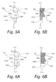
- FIGs. 5A and 5B are schematic cross sectional views of the sealing structure according to the third embodiment of the present invention, and correspond to enlarged views of the portion X in Fig. 1 .
- Fig. 5A is a view with a gasket 400 omitted
- Fig. 5B is a view with the gasket 400 illustrated.
- an annular groove 213 formed on the outer periphery of an injector 200 has a step in its groove bottom, and is composed of a primary annular groove 213a disposed at one side of this step and a secondary annular groove 213b disposed at the other side thereof.
- the step is such that its diameter becomes larger from an atmospheric air side (A) to a combustion chamber side (C).
- the groove bottom of the primary annular groove 213a is composed of two adjacent tapered surfaces in such a manner that the groove bottom first expands thereafter shrinks in diameter in a direction from the atmospheric air side (A) toward the combustion chamber side (C).
- annular protrusion portion 213a1 is formed on the groove bottom of the primary annular groove 213a in the vicinity of a center in an axial direction thereof.
- the groove bottom of the secondary annular groove 213b is composed of a cylindrical surface.
- the configuration in which the primary annular groove 213a is disposed at the atmospheric air side (A), and the secondary annular groove 213b is disposed at the combustion chamber side (C) is similar to the above-mentioned first embodiment.
- the configuration in which a gap D2 is formed to be larger than a minute gap D1 is also similar to the first embodiment.
- the above-mentioned gap D2 is smaller than a distance (the smallest distance) between the groove bottom of the primary annular groove 213a and a mounting hole 310.
- D1 and D2 their explanations are omitted since they are the same as those explained in the first embodiment.
- the same effects as those in the case of the above-mentioned first embodiment can be obtained.
- the annular protrusion portion 213a1 is formed in the vicinity of the center in the axial direction thereof. As a result of this, the contact pressure of the gasket 400 against the mounting hole 310 can be partially increased, thus making it possible to enhance the sealing performance thereof.
- FIGs. 6A and 6B are schematic cross sectional views of the sealing structure according to the fourth embodiment of the present invention, and correspond to enlarged views of the portion X in Fig. 1 .
- Fig. 6A is a view with a gasket 400 omitted
- Fig. 6B is a view with the gasket 400 illustrated.
- an annular groove 214 formed on the outer periphery of an injector 200 has a step in its groove bottom, and is composed of a primary annular groove 214a disposed at one side of this step and a secondary annular groove 214b disposed at the other side thereof.
- the step is such that its diameter becomes larger from an atmospheric air side (A) to a combustion chamber side (C).
- the groove bottom of the primary annular groove 214a is composed of two adjacent tapered surfaces in such a manner that the groove bottom first expands thereafter shrinks in diameter in a direction from the atmospheric air side (A) toward the combustion chamber side (C).
- the groove bottom of the secondary annular groove 214b is composed of two adjacent tapered surfaces in such a manner that the groove bottom first shrinks thereafter expands in diameter in a direction from the atmospheric air side (A) toward the combustion chamber side (C).
- the configuration in which the primary annular groove 214a is disposed at the atmospheric air side (A), and the secondary annular groove 214b is disposed at the combustion chamber side (C) is similar to the above-mentioned first embodiment.
- the configuration in which a gap D2 is formed to be larger than a minute gap D1 is also similar to the first embodiment.
- the above-mentioned gap D2 is smaller than a distance (the smallest distance) between the groove bottom of the primary annular groove 214a and a mounting hole 310.
- D1 and D2 their explanations are omitted since they are the same as those explained in the first embodiment.
- gasket 400 is configured such that it can be filled into a portion of the secondary annular groove 214b where its tapered surface shrinks in diameter in a direction from the atmospheric air side (A) toward the combustion chamber side (C) (refer to Fig. 6B ).
- the gasket 400 is configured such that it can be filled into the portion of the secondary annular groove 214b where its tapered surface shrinks in diameter in the direction from the atmospheric air side (A) toward the combustion chamber side (C).
- the area of a portion of the gasket 400 that receives the pressure of the combustion gas can be made larger, as compared to the case of the first embodiment.
- a force that the gasket 400 receives in the direction towards the primary annular groove 214a from the pressure of the combustion gas becomes larger as compared to the case of the first embodiment, thus making it possible to maintain the filled state of the gasket 400 with respect to the primary annular groove 214a to a greater extent.
- the annular protrusion portion 214a1 is formed in the vicinity of the center in the axial direction thereof. As a result of this, the contact pressure of the gasket 400 against the mounting hole 310 can be partially increased, thus making it possible to enhance the sealing performance thereof.
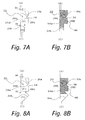
- FIGs. 7A and 7B are schematic cross sectional views of the sealing structure according to the fifth embodiment of the present invention, and correspond to enlarged views of the portion X in Fig. 1 .
- Fig. 7A is a view with a gasket 400 omitted
- Fig. 7B is a view with the gasket 400 illustrated.
- an annular groove 215 formed on the outer periphery of an injector 200 has a step in its groove bottom, and is composed of a primary annular groove 215a disposed at one side of this step and a secondary annular groove 215b disposed at the other side thereof.
- the step is such that its diameter becomes larger from an atmospheric air side (A) to a combustion chamber side (C).
- the primary annular groove 215a has a groove bottom which is composed of a cylindrical surface as a whole, but an annular protrusion portion 215a1 is formed in the vicinity of a center in an axial direction thereof.
- the groove bottom of the secondary annular groove 215b is composed of a cylindrical surface.
- the configuration in which the primary annular groove 215a is disposed at the atmospheric air side (A), and the secondary annular groove 215b is disposed at the combustion chamber side (C) is similar to the above-mentioned first embodiment.
- the configuration in which a gap D2 is formed to be larger than a minute gap D1 is also similar to the first embodiment.
- the above-mentioned gap D2 is smaller than a distance (the smallest distance) between the groove bottom of the primary annular groove 215a and a mounting hole 310.
- D1 and D2 their explanations are omitted since they are the same as those explained in the first embodiment.
- the same effects as those in the case of the above-mentioned first embodiment can be obtained.
- the annular protrusion portion 215a1 is formed in the vicinity of the center in the axial direction thereof. As a result of this, the contact pressure of the gasket 400 against the mounting hole 310 can be partially increased, thus making it possible to enhance the sealing performance thereof.
- FIGs. 8A and 8B are schematic cross sectional views of the sealing structure according to the sixth embodiment of the present invention, and correspond to enlarged views of the portion X in Fig. 1 .
- Fig. 8A is a view with a gasket 400 omitted
- Fig. 8B is a view with the gasket 400 illustrated.
- an annular groove 216 formed on the outer periphery of an injector 200 has a step in its groove bottom, and is composed of a primary annular groove 216a disposed at one side of this step and a secondary annular groove 216b disposed at the other side thereof.
- the step is such that its diameter becomes larger from an atmospheric air side (A) to a combustion chamber side (C).
- the primary annular groove 216a has a groove bottom which is composed of a cylindrical surface as a whole, but an annular protrusion portion 216a1 is formed in the vicinity of a center in an axial direction thereof.
- the groove bottom of the secondary annular groove 216b is composed of two adjacent tapered surfaces in such a manner that the groove bottom first shrinks thereafter expands in diameter in a direction from the atmospheric air side (A) toward the combustion chamber side (C).
- the configuration in which the primary annular groove 216a is disposed at the atmospheric air side (A), and the secondary annular groove 216b is disposed at the combustion chamber side (C) is similar to the above-mentioned first embodiment.
- the configuration in which a gap D2 is formed to be larger than a minute gap D1 is also similar to the first embodiment.
- the above-mentioned gap D2 is smaller than a distance (the smallest distance) between the groove bottom of the primary annular groove 216a and a mounting hole 310.
- D1 and D2 their explanations are omitted since they are the same as those explained in the first embodiment.
- the gasket 400 is configured such that it can be filled into a portion of the secondary annular groove 216b where its tapered surface shrinks in diameter in a direction from the atmospheric air side (A) toward the combustion chamber side (C) (refer to Fig. 8B ).
- the gasket 400 is configured such that it can be filled into the portion of the secondary annular groove 216b where its tapered surface shrinks in diameter in the direction from the atmospheric air side (A) toward the combustion chamber side (C).
- the area of a portion of the gasket 400 that receives the pressure of the combustion gas can be made larger, as compared to the case of the first embodiment.
- a force that the gasket 400 receives in the direction towards the primary annular groove 216a from the pressure of the combustion gas becomes larger as compared to the case of the first embodiment, thus making it possible to maintain the filled state of the gasket 400 with respect to the primary annular groove 216a to a greater extent.
- the annular protrusion portion 216a1 is formed in the vicinity of the center in the axial direction thereof. As a result of this, the contact pressure of the gasket 400 against the mounting hole 310 can be partially increased, thus making it possible to enhance the sealing performance thereof.
Abstract

Description
- The present invention relates to a sealing structure to seal an annular gap between an injector and a housing.
- In a mounting portion of an injector to a cylinder head, an annular gasket which seals an annular gap between the injector and a mounting hole is provided. In such a gasket, there has been known a technique in which the volume of the gasket, when it is in a state where no external force is acting thereon, is made larger than the volume of a space in which the gasket is to be fitted, so that its sealing performance is improved by filling the gasket into an annular groove in which the gasket is to be fitted (refer to a first patent document).
- In such a technique, however, when an injector with the gasket fitted thereon is being inserted into a mounting hole, a large load may be applied, and thus the gasket may be exceptionally deformed or damaged. In addition, it is considered that with such a technique, manual insertion may be difficult.
- First Patent Document: Japanese patent application laid-open No.
2002-81548 - The object of the present invention is to provide a sealing structure that is able to reduce an inserting load, while enhancing a sealing performance.
- In order to solve the above-mentioned problem, the present invention adopts the following means.
- That is, a sealing structure of the present invention is characterized by comprising:
- an injector;
- a housing having a mounting hole in which the injector is mounted; and
- an annular gasket being fitted in an annular groove formed in an outer periphery of the injector to seal an annular gap between the injector and the mounting hole;
- wherein the annular groove has a step on its groove bottom;
- the annular groove comprises:
- a primary annular groove disposed at one side of the step; and
- a secondary annular groove disposed at another side of the step;
- the gasket is disposed so that it is filled into the primary annular groove; and
- a gap between the injector and the mounting hole at a boundary section between the primary annular groove and the secondary annular groove is larger than a minute gap at an opposite side of the secondary annular groove intervened by the primary annular groove.
- According to the present invention, because the gasket is filled into the primary annular groove, it becomes possible to enhance a sealing performance. In addition, because the secondary annular groove is provided, a part of the gasket filled into the primary annular groove can protrude into the secondary annular groove. For that reason, it is possible to reduce an inserting load at the time of inserting the injector with the gasket fitted thereon into the mounting hole. Further, the gap between the injector and the mounting hole at the boundary section between the primary annular groove and the secondary annular groove is larger than the minute gap at the opposite side of the secondary annular groove intervened by the primary annular groove. Hence, it becomes possible to cause a part of the gasket to protrude to the secondary annular groove side in a more reliable manner.
- It is further characterized in that the following relation is satisfied:

where S1 is an area of a cross section of an annular space formed by the primary annular groove and a surface of the mounting hole intersected by a plane including an axis of the annular space, S2 is an area of a cross section of an annular space formed by the secondary annular groove and the surface of the mounting hole intersected by a plane including an axis of the annular space, S3 is an area of a cross section of the gasket intersected by a plane including an axis of the gasket when the gasket is in a state of not being subjected to any external force. - According to this, the gasket can be filled into the primary annular groove, while the gasket does not completely fill the secondary annular groove. For that reason, it is possible to suppress the gasket from protruding into the outside of the annular groove. In addition, along with this, it is also possible to suppress the inserting load.
- It is preferable that the secondary annular groove be disposed at a combustion chamber side with respect to the primary annular groove.
- According to this, when the injector with the gasket fitted thereon is inserted into the mounting hole, frictional resistance against the gasket acts on the opposite side of the combustion chamber, thus the gasket can be filled into the primary annular groove side in a more reliable manner. In addition, a portion of the gasket which has been filled into the secondary annular groove side is subjected to the pressure of a combustion gas, thus the filled state of the gasket with respect to the primary annular groove can be maintained, thereby making it possible to enhance the sealing performance thereof. Here, note that even if the gasket has been deformed due to creep over time, the gasket can stably maintain its filled state with respect to the primary annular groove by receiving the pressure of the combustion gas and the durability thereof can also be improved.
- It is preferable that a shape of the cross section of the gasket intersected by the plane including the axis of the gasket when the gasket is in a state of not being subjected to any external force is rectangular.
- Here, it is preferable that the primary annular groove has an annular protrusion portion formed on its groove bottom in a vicinity of a center in an axial direction thereof.
- As a result of this, the contact pressure of the gasket with respect to the mounting hole can be partially made high, thus making it possible to enhance the sealing performance.
- Here, note that the above-mentioned respective configurations can be combined with one another wherever possible.
- As explained above, according to the present invention, it is possible to reduce the inserting load, while enhancing the sealing performance.
-
-
Fig. 1 is a schematic cross sectional view showing a sealing structure according to an embodiment of the present invention. -
Fig. 2 is a partially broken cross sectional view of a gasket according to the embodiment of the present invention. -
Figs. 3A and 3B are schematic cross sectional views of a sealing structure according to a first embodiment of the present invention. -
Figs. 4A and 4B are schematic cross sectional views of a sealing structure according to a second embodiment of the present invention. -
Figs. 5A and 5B are schematic cross sectional views of a sealing structure according to a third embodiment of the present invention. -
Figs. 6A and 6B are schematic cross sectional views of a sealing structure according to a fourth embodiment of the present invention. -
Figs. 7A and 7B are schematic cross sectional views of a sealing structure according to a fifth embodiment of the present invention. -
Figs. 8A and 8B are schematic cross sectional views of a sealing structure according to a sixth embodiment of the present invention. - Hereinafter, modes for carrying out the present invention will be exemplarily described in detail based on embodiments thereof with reference to the attached drawings. However, the dimensions, materials, shapes, relative arrangements and so on of component parts described in the embodiments are not intended to limit the scope of the present invention to these alone in particular as long as there are no specific descriptions.
- Referring to
Figs. 1 and 2 , a sealing structure according to an embodiment of the present invention will be explained. Thesealing structure 100 according to this embodiment is composed of aninjector 200, ahousing 300 having amounting hole 310 in which theinjector 200 is mounted, and agasket 400. Here, note that inFig. 1 , with respect to theinjector 200, only the vicinity of a tip end thereof which constitutes the sealing structure is shown. In addition, thehousing 300 corresponds to a cylinder head of an engine, wherein only a portion of thehousing 300 which constitutes the sealing structure is shown. - The
gasket 400 is an annular member composed of PTFE (tetrafluoroethylene resin). Thegasket 400 is also a member having a cylindrical shape, wherein the shape of a cross section thereof intersected by a plane including its axis is a rectangle when thegasket 400 is in a state of not being subjected to any external force (refer toFig. 2 ). Thisgasket 400 is fitted in anannular groove 210 formed in an outer periphery of theinjector 200, and seals an annular gap between theinjector 200 and the mountinghole 310. - Referring to
Figs. 3A and 3B , a sealing structure according to a first embodiment of the present invention will be explained.Figs. 3A and 3B are schematic cross sectional views of the sealing structure according to the first embodiment of the present invention, and correspond to enlarged views of a portion X inFig. 1 . Here, note thatFig. 3A is a view with agasket 400 omitted, andFig. 3B is a view with thegasket 400 illustrated. - In this embodiment, an
annular groove 211 formed on the outer periphery of aninjector 200 has a step on its groove bottom, and is composed of a primaryannular groove 211 a disposed at one side of this step and a secondaryannular groove 211b disposed at the other side thereof. Here, note that the step is such that its diameter becomes larger from an atmospheric air side (A) to a combustion chamber side (C). The groove bottoms of the primaryannular groove 211 a and the secondaryannular groove 211b are each composed of a cylindrical surface. The primaryannular groove 211a is disposed at the atmospheric air side (A), and the secondaryannular groove 211b is disposed at the combustion chamber side (C). Then, it is configured such that a gap D2 between theinjector 200 and the mountinghole 310 at a boundary section between the primaryannular groove 211 a and the secondaryannular groove 211b is larger than a minute gap D1 at the opposite side of the secondaryannular groove 211b intervened by the primaryannular groove 211 a. Here, note that the above-mentioned gap D2 is smaller than a distance between the groove bottom of the primaryannular groove 211a and the mountinghole 310. - In addition, in this embodiment, with respect to areas S1, S2 shown in
Fig. 3A and an area S3 shown inFig. 2 , it is configured such that these areas satisfy the relation S1 < S3 < (S1 + S2). Here, the area S1 is an area of a cross section of an annular space formed by the primaryannular groove 211 a and a surface of the mountinghole 310 intersected by a plane including an axis of the annular space. And, the area S2 is an area of a cross section of an annular space formed by the secondaryannular groove 211b and the surface of the mountinghole 310 intersected by a plane including an axis of the annular space. Moreover, the area S3 is an area of a cross section of thegasket 400 intersected by a plane including its axis whengasket 400 is in a state of not being subjected to any external force. - Then, when inserting the
injector 200 into thehousing 300, theinjector 200 is fitted into the mountinghole 310 in a direction from the atmospheric air side (A) toward the combustion chamber side (C) with thegasket 400 being fitted into theannular groove 211 of theinjector 200. As a result of this, thegasket 400, which has a rectangular cross section when it is in a state of not being subjected to any external force, receives a force towards inside from an inner peripheral surface of the mountinghole 310 and deforms to conform with the shape of theannular groove 211. More specifically, thegasket 400 is filled (substantially) completely with respect to the primaryannular groove 211a, and a part of a remaining portion of the gasket is filled into the secondaryannular groove 211b (refer toFig. 3B ). - In accordance with the sealing structure according to this embodiment as configured in the above manner, because the
gasket 400 is (substantially) completely filled into the primaryannular groove 211a, it becomes possible to enhance the sealing performance thereof. In addition, because the secondaryannular groove 211b is provided, the part of thegasket 400 filled into the primaryannular groove 211a can protrude into the secondaryannular groove 211b. For that reason, it is possible to reduce the inserting load at the time of inserting theinjector 200 with thegasket 400 fitted thereon into the mountinghole 310. Accordingly, it is possible to reduce the inserting load, while enhancing the sealing performance. - In addition, the gap D2 between the
injector 200 and the mountinghole 310 at the boundary section between the primaryannular groove 211a and the secondaryannular groove 211b is larger than the minute gap D1 at the opposite side of the secondaryannular groove 211b intervened by the primaryannular groove 211a. Hence, it becomes possible to cause a part of thegasket 400 to protrude to the secondaryannular groove 211b side in a more reliable manner. - Moreover, as mentioned above, with respect to the areas S1, S2, S3 shown in
Figs. 2 and3A , because they are configured to satisfy the relation S1 < S3 < (S1 + S2), thegasket 400 can be filled (substantially) completely into the primaryannular groove 211a, while it is possible to suppress thegasket 400 from completely filling the secondaryannular groove 211 b. Accordingly, it is possible to suppress thegasket 400 from protruding into the outside of theannular groove 211. In addition, along with this, it is also possible to suppress the inserting load. - Further, the secondary
annular groove 211b is disposed at the combustion chamber side (C) with respect to the primaryannular groove 211a. For that reason, when theinjector 200 with thegasket 400 fitted thereon is inserted into the mountinghole 310, frictional resistance against thegasket 400 acts on the opposite side of the combustion chamber (C). Accordingly, thegasket 400 can be filled into the primaryannular groove 211a side in a more reliable manner. In addition, a portion of thegasket 400 which has been filled into the secondaryannular groove 211b side is subjected to the pressure of a combustion gas, thus the filled state of thegasket 400 with respect to the primaryannular groove 211a can be maintained, thereby making it possible to enhance the sealing performance thereof. Here, note that even if thegasket 400 has been deformed due to creep over time, thegasket 400 can stably maintain its filled state with respect to the primaryannular groove 211 a by receiving the pressure of the combustion gas and the durability thereof can also be improved. - Referring to
Figs. 4A and 4B , a sealing structure according to a second embodiment of the present invention will be explained.Figs. 4A and 4B are schematic cross sectional views of the sealing structure according to the second embodiment of the present invention, and correspond to enlarged views of the portion X inFig. 1 . Here, note thatFig. 4A is a view with agasket 400 omitted, andFig. 4B is a view with thegasket 400 illustrated. - In this embodiment, an
annular groove 212 formed on the outer periphery of aninjector 200 has a step in its groove bottom, and is composed of a primaryannular groove 212a disposed at one side of this step and a secondaryannular groove 212b disposed at the other side thereof. Here, note that the step is such that its diameter becomes larger from an atmospheric air side (A) to a combustion chamber side (C). Similar to the case of the above-mentioned first embodiment, the groove bottom of the primaryannular groove 212a is composed of a cylindrical surface. In contrast to this, in this embodiment, the groove bottom of the secondaryannular groove 212b is composed of two adjacent tapered surfaces in such a manner that the groove bottom first shrinks thereafter expands in diameter in a direction from the atmospheric air side (A) toward the combustion chamber side (C). - The configuration in which the primary
annular groove 212a is disposed at the atmospheric air side (A), and the secondaryannular groove 212b is disposed at the combustion chamber side (C) is similar to the above-mentioned first embodiment. In addition, the configuration in which a gap D2 is formed to be larger than a minute gap D1 is also similar to the first embodiment. Here, note that the above-mentioned gap D2 is smaller than a distance between the groove bottom of the primaryannular groove 212a and a mountinghole 310. As for the definitions of D1 and D2, their explanations are omitted since they are the same as those explained in the first embodiment. Also, with respect to areas S1, S2 shown inFig. 4A and the area S3 shown inFig. 2 , they are configured to satisfy the relation S1 < S3 < (S1 + S2), as in the above-mentioned first embodiment. As for the definitions of S1, S2, S3, their explanations are omitted since they are the same as those explained in the first embodiment. Further, as for a method to insert theinjector 200, as well as a behavior and a state of thegasket 400 when theinjector 200 has been inserted, their explanations are omitted since they are the same as those explained in the first embodiment. Here, note that thegasket 400 is configured such that it can be filled into a portion of the secondaryannular groove 212b where its tapered surface shrinks in diameter in a direction from the atmospheric air side (A) toward the combustion chamber side (C) (refer toFig. 4B ). - In the sealing structure according to this embodiment as configured in the above manner, too, the same effects as those in the case of the above-mentioned first embodiment can be obtained. In addition, in the case of this embodiment, the
gasket 400 is configured such that it can be filled into the portion of the secondaryannular groove 212b where its tapered surface shrinks in diameter in the direction from the atmospheric air side (A) toward the combustion chamber side (C). As a result of this, the area of a portion of thegasket 400 that receives the pressure of the combustion gas can be made larger, as compared to the case of the first embodiment. According to this, a force that thegasket 400 receives in the direction towards the primaryannular groove 212a from the pressure of the combustion gas becomes larger as compared to the case of the first embodiment, thus making it possible to maintain the filled state of thegasket 400 with respect to the primaryannular groove 212a to a greater extent. - Referring to
Figs. 5A and 5B , a sealing structure according to a third embodiment of the present invention will be explained.Figs. 5A and 5B are schematic cross sectional views of the sealing structure according to the third embodiment of the present invention, and correspond to enlarged views of the portion X inFig. 1 . Here, note thatFig. 5A is a view with agasket 400 omitted, andFig. 5B is a view with thegasket 400 illustrated. - In this embodiment, an
annular groove 213 formed on the outer periphery of aninjector 200 has a step in its groove bottom, and is composed of a primaryannular groove 213a disposed at one side of this step and a secondaryannular groove 213b disposed at the other side thereof. Here, note that the step is such that its diameter becomes larger from an atmospheric air side (A) to a combustion chamber side (C). The groove bottom of the primaryannular groove 213a is composed of two adjacent tapered surfaces in such a manner that the groove bottom first expands thereafter shrinks in diameter in a direction from the atmospheric air side (A) toward the combustion chamber side (C). As a result of this, an annular protrusion portion 213a1 is formed on the groove bottom of the primaryannular groove 213a in the vicinity of a center in an axial direction thereof. In addition, similar to the case of the above-mentioned first embodiment, the groove bottom of the secondaryannular groove 213b is composed of a cylindrical surface. - The configuration in which the primary
annular groove 213a is disposed at the atmospheric air side (A), and the secondaryannular groove 213b is disposed at the combustion chamber side (C) is similar to the above-mentioned first embodiment. In addition, the configuration in which a gap D2 is formed to be larger than a minute gap D1 is also similar to the first embodiment. Here, note that the above-mentioned gap D2 is smaller than a distance (the smallest distance) between the groove bottom of the primaryannular groove 213a and a mountinghole 310. As for the definitions of D1 and D2, their explanations are omitted since they are the same as those explained in the first embodiment. Also, with respect to areas S1, S2 shown inFig. 5A and the area S3 shown inFig. 2 , they are configured to satisfy the relation S1 < S3 < (S1 + S2), as in the above-mentioned first embodiment. As for the definitions of S1, S2, S3, their explanations are omitted since they are the same as those explained in the first embodiment. Further, as for a method to insert theinjector 200, as well as a behavior and a state of thegasket 400 when theinjector 200 has been inserted, their explanations are omitted since they are the same as those explained in the first embodiment. - In the sealing structure according to this embodiment as configured in the above manner, too, the same effects as those in the case of the above-mentioned first embodiment can be obtained. In addition, in the case of this embodiment, on the groove bottom of the primary
annular groove 213a, the annular protrusion portion 213a1 is formed in the vicinity of the center in the axial direction thereof. As a result of this, the contact pressure of thegasket 400 against the mountinghole 310 can be partially increased, thus making it possible to enhance the sealing performance thereof. - Referring to
Figs. 6A and 6B , a sealing structure according to a fourth embodiment of the present invention will be explained.Figs. 6A and 6B are schematic cross sectional views of the sealing structure according to the fourth embodiment of the present invention, and correspond to enlarged views of the portion X inFig. 1 . Here, note thatFig. 6A is a view with agasket 400 omitted, andFig. 6B is a view with thegasket 400 illustrated. - In this embodiment, an
annular groove 214 formed on the outer periphery of aninjector 200 has a step in its groove bottom, and is composed of a primaryannular groove 214a disposed at one side of this step and a secondaryannular groove 214b disposed at the other side thereof. Here, note that the step is such that its diameter becomes larger from an atmospheric air side (A) to a combustion chamber side (C). Similar to the case of the third embodiment, the groove bottom of the primaryannular groove 214a is composed of two adjacent tapered surfaces in such a manner that the groove bottom first expands thereafter shrinks in diameter in a direction from the atmospheric air side (A) toward the combustion chamber side (C). In addition, the groove bottom of the secondaryannular groove 214b is composed of two adjacent tapered surfaces in such a manner that the groove bottom first shrinks thereafter expands in diameter in a direction from the atmospheric air side (A) toward the combustion chamber side (C). - The configuration in which the primary
annular groove 214a is disposed at the atmospheric air side (A), and the secondaryannular groove 214b is disposed at the combustion chamber side (C) is similar to the above-mentioned first embodiment. In addition, the configuration in which a gap D2 is formed to be larger than a minute gap D1 is also similar to the first embodiment. Here, note that the above-mentioned gap D2 is smaller than a distance (the smallest distance) between the groove bottom of the primaryannular groove 214a and a mountinghole 310. As for the definitions of D1 and D2, their explanations are omitted since they are the same as those explained in the first embodiment. Also, with respect to areas S1, S2 shown inFig. 6A and the area S3 shown inFig. 2 , they are configured to satisfy the relation S1 < S3 < (S1 + S2), as in the above-mentioned first embodiment. As for the definitions of S1, S2, S3, their explanations are omitted since they are the same as those explained in the first embodiment. Further, as for a method to insert theinjector 200, as well as a behavior and a state of thegasket 400 when theinjector 200 has been inserted, their explanations are omitted since they are the same as those explained in the first embodiment. Here, note that thegasket 400 is configured such that it can be filled into a portion of the secondaryannular groove 214b where its tapered surface shrinks in diameter in a direction from the atmospheric air side (A) toward the combustion chamber side (C) (refer toFig. 6B ). - In the sealing structure according to this embodiment as configured in the above manner, too, the same effects as those in the case of the above-mentioned first embodiment can be obtained. In addition, in the case of this embodiment, the
gasket 400 is configured such that it can be filled into the portion of the secondaryannular groove 214b where its tapered surface shrinks in diameter in the direction from the atmospheric air side (A) toward the combustion chamber side (C). As a result of this, the area of a portion of thegasket 400 that receives the pressure of the combustion gas can be made larger, as compared to the case of the first embodiment. According to this, a force that thegasket 400 receives in the direction towards the primaryannular groove 214a from the pressure of the combustion gas becomes larger as compared to the case of the first embodiment, thus making it possible to maintain the filled state of thegasket 400 with respect to the primaryannular groove 214a to a greater extent. Moreover, in the case of this embodiment, on the groove bottom of the primaryannular groove 214a, the annular protrusion portion 214a1 is formed in the vicinity of the center in the axial direction thereof. As a result of this, the contact pressure of thegasket 400 against the mountinghole 310 can be partially increased, thus making it possible to enhance the sealing performance thereof. - Referring to
Figs. 7A and 7B , a sealing structure according to a fifth embodiment of the present invention will be explained.Figs. 7A and 7B are schematic cross sectional views of the sealing structure according to the fifth embodiment of the present invention, and correspond to enlarged views of the portion X inFig. 1 . Here, note thatFig. 7A is a view with agasket 400 omitted, andFig. 7B is a view with thegasket 400 illustrated. - In this embodiment, an
annular groove 215 formed on the outer periphery of aninjector 200 has a step in its groove bottom, and is composed of a primaryannular groove 215a disposed at one side of this step and a secondaryannular groove 215b disposed at the other side thereof. Here, note that the step is such that its diameter becomes larger from an atmospheric air side (A) to a combustion chamber side (C). The primaryannular groove 215a has a groove bottom which is composed of a cylindrical surface as a whole, but an annular protrusion portion 215a1 is formed in the vicinity of a center in an axial direction thereof. In addition, similar to the case of the above-mentioned first embodiment, the groove bottom of the secondaryannular groove 215b is composed of a cylindrical surface. - The configuration in which the primary
annular groove 215a is disposed at the atmospheric air side (A), and the secondaryannular groove 215b is disposed at the combustion chamber side (C) is similar to the above-mentioned first embodiment. In addition, the configuration in which a gap D2 is formed to be larger than a minute gap D1 is also similar to the first embodiment. Here, note that the above-mentioned gap D2 is smaller than a distance (the smallest distance) between the groove bottom of the primaryannular groove 215a and a mountinghole 310. As for the definitions of D1 and D2, their explanations are omitted since they are the same as those explained in the first embodiment. Also, with respect to areas S1, S2 shown inFig. 7A and the area S3 shown inFig. 2 , they are configured to satisfy the relation S1 < S3 < (S1 + S2), as in the above-mentioned first embodiment. As for the definitions of S1, S2, S3, their explanations are omitted since they are the same as those explained in the first embodiment. Further, as for a method to insert theinjector 200, as well as a behavior and a state of thegasket 400 when theinjector 200 has been inserted, their explanations are omitted since they are the same as those explained in the first embodiment. - In the sealing structure according to this embodiment as configured in the above manner, too, the same effects as those in the case of the above-mentioned first embodiment can be obtained. In addition, in the case of this embodiment, on the groove bottom of the primary
annular groove 215a, the annular protrusion portion 215a1 is formed in the vicinity of the center in the axial direction thereof. As a result of this, the contact pressure of thegasket 400 against the mountinghole 310 can be partially increased, thus making it possible to enhance the sealing performance thereof. - Referring to
Figs. 8A and 8B , a sealing structure according to a sixth embodiment of the present invention will be explained.Figs. 8A and 8B are schematic cross sectional views of the sealing structure according to the sixth embodiment of the present invention, and correspond to enlarged views of the portion X inFig. 1 . Here, note thatFig. 8A is a view with agasket 400 omitted, andFig. 8B is a view with thegasket 400 illustrated. - In this embodiment, an
annular groove 216 formed on the outer periphery of aninjector 200 has a step in its groove bottom, and is composed of a primaryannular groove 216a disposed at one side of this step and a secondaryannular groove 216b disposed at the other side thereof. Here, note that the step is such that its diameter becomes larger from an atmospheric air side (A) to a combustion chamber side (C). The primaryannular groove 216a has a groove bottom which is composed of a cylindrical surface as a whole, but an annular protrusion portion 216a1 is formed in the vicinity of a center in an axial direction thereof. In addition, the groove bottom of the secondaryannular groove 216b is composed of two adjacent tapered surfaces in such a manner that the groove bottom first shrinks thereafter expands in diameter in a direction from the atmospheric air side (A) toward the combustion chamber side (C). - The configuration in which the primary
annular groove 216a is disposed at the atmospheric air side (A), and the secondaryannular groove 216b is disposed at the combustion chamber side (C) is similar to the above-mentioned first embodiment. In addition, the configuration in which a gap D2 is formed to be larger than a minute gap D1 is also similar to the first embodiment. Here, note that the above-mentioned gap D2 is smaller than a distance (the smallest distance) between the groove bottom of the primaryannular groove 216a and a mountinghole 310. As for the definitions of D1 and D2, their explanations are omitted since they are the same as those explained in the first embodiment. Also, with respect to areas S1, S2 shown inFig. 8A and the area S3 shown inFig. 2 , they are configured to satisfy the relation S1 < S3 < (S1 + S2), as in the above-mentioned first embodiment. As for the definitions of S1, S2, S3, their explanations are omitted since they are the same as those explained in the first embodiment. Further, as for a method to insert theinjector 200, as well as a behavior and a state of thegasket 400 when theinjector 200 has been inserted, their explanations are omitted since they are the same as those explained in the first embodiment. Here, note that thegasket 400 is configured such that it can be filled into a portion of the secondaryannular groove 216b where its tapered surface shrinks in diameter in a direction from the atmospheric air side (A) toward the combustion chamber side (C) (refer toFig. 8B ). - In the sealing structure according to this embodiment as configured in the above manner, too, the same effects as those in the case of the above-mentioned first embodiment can be obtained. In addition, in the case of this embodiment, the
gasket 400 is configured such that it can be filled into the portion of the secondaryannular groove 216b where its tapered surface shrinks in diameter in the direction from the atmospheric air side (A) toward the combustion chamber side (C). As a result of this, the area of a portion of thegasket 400 that receives the pressure of the combustion gas can be made larger, as compared to the case of the first embodiment. According to this, a force that thegasket 400 receives in the direction towards the primaryannular groove 216a from the pressure of the combustion gas becomes larger as compared to the case of the first embodiment, thus making it possible to maintain the filled state of thegasket 400 with respect to the primaryannular groove 216a to a greater extent. Moreover, in the case of this embodiment, on the groove bottom of the primaryannular groove 216a, the annular protrusion portion 216a1 is formed in the vicinity of the center in the axial direction thereof. As a result of this, the contact pressure of thegasket 400 against the mountinghole 310 can be partially increased, thus making it possible to enhance the sealing performance thereof. -
- 100
- sealing device
- 200
- injector
- 210, 211, 212, 213, 214, 215, 216
- annular groove
- 211a, 212a, 213a, 214a, 215a, 216a
- primary annular groove
- 211b, 212b, 213b, 214b, 215b, 216b
- secondary annular groove
- 213a1, 214a1, 215a1, 216a1
- protrusion portion
- 300
- housing
- 310
- mounting hole
- 400
- gasket
Claims (5)
- A sealing structure characterized by comprising:an injector;a housing having a mounting hole in which the injector is mounted; andan annular gasket being fitted in an annular groove formed in an outer periphery of the injector to seal an annular gap between the injector and the mounting hole;wherein the annular groove has a step on its groove bottom;the annular groove comprises:a primary annular groove disposed at one side of the step; anda secondary annular groove disposed at another side of the step;the gasket is disposed so that it is filled into the primary annular groove; anda gap between the injector and the mounting hole at a boundary section between the primary annular groove and the secondary annular groove is larger than a minute gap at an opposite side of the secondary annular groove intervened by the primary annular groove.
- The sealing structure as set forth in claim 1, characterized in that the following relation is satisfied:

where S1 is an area of a cross section of an annular space formed by the primary annular groove and a surface of the mounting hole intersected by a plane including an axis of the annular space, S2 is an area of a cross section of an annular space formed by the secondary annular groove and the surface of the mounting hole intersected by a plane including an axis of the annular space, S3 is an area of a cross section of the gasket intersected by a plane including an axis of the gasket when the gasket is in a state of not being subjected to any external force. - The sealing structure as set forth in claim 1 or 2, characterized in that the secondary annular groove is disposed at a combustion chamber side with respect to the primary annular groove.
- The sealing structure as set forth in claim 1, 2 or 3, characterized in that a shape of the cross section of the gasket intersected by the plane including the axis of the gasket when the gasket is in a state of not being subjected to any external force is rectangular.
- The sealing structure as set forth in claim 4, characterized in that the primary annular groove has an annular protrusion portion formed on its groove bottom in a vicinity of a center in an axial direction thereof.
Applications Claiming Priority (2)
| Application Number | Priority Date | Filing Date | Title |
|---|---|---|---|
| JP2012038641A JP5867158B2 (en) | 2012-02-24 | 2012-02-24 | Sealing structure |
| PCT/JP2012/080330 WO2013125116A1 (en) | 2012-02-24 | 2012-11-22 | Sealing structure |
Publications (2)
| Publication Number | Publication Date |
|---|---|
| EP2818688A1 true EP2818688A1 (en) | 2014-12-31 |
| EP2818688A4 EP2818688A4 (en) | 2015-10-21 |
Family
ID=49005316
Family Applications (1)
| Application Number | Title | Priority Date | Filing Date |
|---|---|---|---|
| EP12869461.9A Withdrawn EP2818688A4 (en) | 2012-02-24 | 2012-11-22 | Sealing structure |
Country Status (6)
| Country | Link |
|---|---|
| US (1) | US20150035237A1 (en) |
| EP (1) | EP2818688A4 (en) |
| JP (1) | JP5867158B2 (en) |
| KR (1) | KR20140105619A (en) |
| CN (1) | CN104136762B (en) |
| WO (1) | WO2013125116A1 (en) |
Families Citing this family (5)
| Publication number | Priority date | Publication date | Assignee | Title |
|---|---|---|---|---|
| CN106321826A (en) * | 2015-06-17 | 2017-01-11 | 镇江市中能机械设备有限公司 | A T-shaped gasket |
| CN106640405B (en) * | 2016-12-28 | 2020-05-15 | 沪东重机有限公司 | Internal sealing ring structure of low-speed diesel engine stuffing box |
| JP6806037B2 (en) * | 2017-11-13 | 2021-01-06 | トヨタ自動車株式会社 | Injector mounting structure |
| DE102017221203A1 (en) | 2017-11-27 | 2019-05-29 | Hyundai Motor Company | A fuel injection system and method of operating a fuel injection system |
| US20230349467A1 (en) * | 2020-11-20 | 2023-11-02 | Nok Corporation | Sealing structure and assembling method of sealing structure |
Citations (4)
| Publication number | Priority date | Publication date | Assignee | Title |
|---|---|---|---|---|
| WO1999061786A1 (en) * | 1998-05-27 | 1999-12-02 | Caterpillar Inc. | Fuel injector isolation |
| JP2002089412A (en) * | 2000-09-08 | 2002-03-27 | Toyota Motor Corp | Fitting structure of injector |
| EP1357284A1 (en) * | 2000-12-26 | 2003-10-29 | Toyota Jidosha Kabushiki Kaisha | Combustion gas seal for injector and sealing structure with the combustion gas seal |
| WO2007058103A1 (en) * | 2005-11-16 | 2007-05-24 | Toyota Jidosha Kabushiki Kaisha | Fuel injection valve |
Family Cites Families (17)
| Publication number | Priority date | Publication date | Assignee | Title |
|---|---|---|---|---|
| US4579354A (en) * | 1984-12-05 | 1986-04-01 | Vassallo Research And Development Corporation | Gasket |
| JPH024281Y2 (en) * | 1985-01-09 | 1990-01-31 | ||
| US4938193A (en) * | 1987-06-15 | 1990-07-03 | Stanadyne Automotive Corp. | Fuel injection nozzle |
| US5219189A (en) * | 1989-12-11 | 1993-06-15 | Pont-A-Mousson S.A. | Composite gasket for the locked assembly of spigot and socket pipes |
| JP2932654B2 (en) * | 1990-09-25 | 1999-08-09 | 富士電機株式会社 | Sealing device |
| DE4413863C2 (en) * | 1994-04-21 | 1996-03-28 | Parker Praedifa Gmbh | Sealing arrangement for injectors on fuel supply lines |
| US5752487A (en) * | 1997-06-11 | 1998-05-19 | Caterpillar Inc. | Injector combustion gas seal |
| DE10027662A1 (en) * | 2000-06-03 | 2001-12-06 | Bosch Gmbh Robert | Sealing unit for a fuel injection valve in a cylider head bore comprises a main body with an axial bore with an enlarged section which accommodates a sealing element |
| DE10038300A1 (en) * | 2000-08-05 | 2002-02-14 | Bosch Gmbh Robert | Fuel injector |
| US6457718B1 (en) * | 2000-08-25 | 2002-10-01 | S & B Technical Products, Inc. | Method of forming a pipe joint between metal pipes using an extensible gasket |
| JP4407863B2 (en) * | 2000-09-04 | 2010-02-03 | 本田技研工業株式会社 | Sealing device |
| JP2002081548A (en) * | 2000-09-04 | 2002-03-22 | Honda Motor Co Ltd | Seal structure |
| JP3746214B2 (en) * | 2001-09-10 | 2006-02-15 | 大電株式会社 | Embolization structure |
| US7140618B2 (en) * | 2003-01-16 | 2006-11-28 | Vassallo Research & Development Corporation | Socket with dual-functional composite gasket |
| JP4267433B2 (en) * | 2003-11-25 | 2009-05-27 | トヨタ自動車株式会社 | Combustion gas seal for fuel injection valve |
| JP4311218B2 (en) * | 2004-02-12 | 2009-08-12 | Nok株式会社 | Seal structure |
| FR2908171B1 (en) * | 2006-11-02 | 2009-01-09 | Bosch Gmbh Robert | DISC BRAKE |
-
2012
- 2012-02-24 JP JP2012038641A patent/JP5867158B2/en active Active
- 2012-11-22 CN CN201280070194.1A patent/CN104136762B/en active Active
- 2012-11-22 US US14/379,928 patent/US20150035237A1/en not_active Abandoned
- 2012-11-22 EP EP12869461.9A patent/EP2818688A4/en not_active Withdrawn
- 2012-11-22 KR KR1020147022754A patent/KR20140105619A/en not_active Application Discontinuation
- 2012-11-22 WO PCT/JP2012/080330 patent/WO2013125116A1/en active Application Filing
Patent Citations (4)
| Publication number | Priority date | Publication date | Assignee | Title |
|---|---|---|---|---|
| WO1999061786A1 (en) * | 1998-05-27 | 1999-12-02 | Caterpillar Inc. | Fuel injector isolation |
| JP2002089412A (en) * | 2000-09-08 | 2002-03-27 | Toyota Motor Corp | Fitting structure of injector |
| EP1357284A1 (en) * | 2000-12-26 | 2003-10-29 | Toyota Jidosha Kabushiki Kaisha | Combustion gas seal for injector and sealing structure with the combustion gas seal |
| WO2007058103A1 (en) * | 2005-11-16 | 2007-05-24 | Toyota Jidosha Kabushiki Kaisha | Fuel injection valve |
Non-Patent Citations (1)
| Title |
|---|
| See also references of WO2013125116A1 * |
Also Published As
| Publication number | Publication date |
|---|---|
| JP2013174287A (en) | 2013-09-05 |
| KR20140105619A (en) | 2014-09-01 |
| US20150035237A1 (en) | 2015-02-05 |
| CN104136762B (en) | 2016-10-19 |
| WO2013125116A1 (en) | 2013-08-29 |
| CN104136762A (en) | 2014-11-05 |
| JP5867158B2 (en) | 2016-02-24 |
| EP2818688A4 (en) | 2015-10-21 |
Similar Documents
| Publication | Publication Date | Title |
|---|---|---|
| US10612660B2 (en) | Gasket | |
| EP2818688A1 (en) | Sealing structure | |
| EP2341268B1 (en) | Gasket | |
| JP5692504B2 (en) | gasket | |
| KR101929068B1 (en) | Tube joint | |
| JP5374559B2 (en) | Sealing structure | |
| JP4853633B2 (en) | Sealing device | |
| EP3067592A1 (en) | Gasket and sealing structure | |
| US9664162B2 (en) | Sealing structure | |
| US9273655B2 (en) | Sealing device | |
| US11424599B2 (en) | Spark plug with insulator with particular shape | |
| US20160141793A1 (en) | Liquid proof connector | |
| US10872723B2 (en) | Ignition coil for internal combustion engine | |
| CN106195456B (en) | Elastomeric seal and seal assembly | |
| JP2010014201A (en) | Sealing device | |
| JP2009024712A (en) | Sealing device | |
| CN110691930B (en) | Sealing device | |
| CN216289495U (en) | Solid outer sealing washer, spark plug body, spark plug and vehicle engine | |
| JP4805568B2 (en) | Seal structure | |
| JP2008075483A (en) | Seal structure of engine | |
| JP2018182304A (en) | Ignition coil for internal combustion engine | |
| JP6050157B2 (en) | Injector packing |
Legal Events
| Date | Code | Title | Description |
|---|---|---|---|
| PUAI | Public reference made under article 153(3) epc to a published international application that has entered the european phase |
Free format text: ORIGINAL CODE: 0009012 |
|
| 17P | Request for examination filed |
Effective date: 20140825 |
|
| AK | Designated contracting states |
Kind code of ref document: A1 Designated state(s): AL AT BE BG CH CY CZ DE DK EE ES FI FR GB GR HR HU IE IS IT LI LT LU LV MC MK MT NL NO PL PT RO RS SE SI SK SM TR |
|
| AX | Request for extension of the european patent |
Extension state: BA ME |
|
| DAX | Request for extension of the european patent (deleted) | ||
| RA4 | Supplementary search report drawn up and despatched (corrected) |
Effective date: 20150918 |
|
| RIC1 | Information provided on ipc code assigned before grant |
Ipc: F02M 61/16 20060101AFI20150914BHEP Ipc: F02M 61/14 20060101ALI20150914BHEP Ipc: F16J 15/10 20060101ALI20150914BHEP |
|
| 17Q | First examination report despatched |
Effective date: 20170410 |
|
| STAA | Information on the status of an ep patent application or granted ep patent |
Free format text: STATUS: THE APPLICATION HAS BEEN WITHDRAWN |
|
| 18W | Application withdrawn |
Effective date: 20170620 |