EP2818635B1 - Kompressortrommel einer axialen Turbomaschine mit gemischter Befestigung der Laufradschaufeln - Google Patents
Kompressortrommel einer axialen Turbomaschine mit gemischter Befestigung der Laufradschaufeln Download PDFInfo
- Publication number
- EP2818635B1 EP2818635B1 EP13173510.2A EP13173510A EP2818635B1 EP 2818635 B1 EP2818635 B1 EP 2818635B1 EP 13173510 A EP13173510 A EP 13173510A EP 2818635 B1 EP2818635 B1 EP 2818635B1
- Authority
- EP
- European Patent Office
- Prior art keywords
- drum
- row
- blades
- rotor
- annular
- Prior art date
- Legal status (The legal status is an assumption and is not a legal conclusion. Google has not performed a legal analysis and makes no representation as to the accuracy of the status listed.)
- Active
Links
Images
Classifications
-
- F—MECHANICAL ENGINEERING; LIGHTING; HEATING; WEAPONS; BLASTING
- F01—MACHINES OR ENGINES IN GENERAL; ENGINE PLANTS IN GENERAL; STEAM ENGINES
- F01D—NON-POSITIVE DISPLACEMENT MACHINES OR ENGINES, e.g. STEAM TURBINES
- F01D5/00—Blades; Blade-carrying members; Heating, heat-insulating, cooling or antivibration means on the blades or the members
- F01D5/02—Blade-carrying members, e.g. rotors
- F01D5/06—Rotors for more than one axial stage, e.g. of drum or multiple disc type; Details thereof, e.g. shafts, shaft connections
-
- F—MECHANICAL ENGINEERING; LIGHTING; HEATING; WEAPONS; BLASTING
- F01—MACHINES OR ENGINES IN GENERAL; ENGINE PLANTS IN GENERAL; STEAM ENGINES
- F01D—NON-POSITIVE DISPLACEMENT MACHINES OR ENGINES, e.g. STEAM TURBINES
- F01D11/00—Preventing or minimising internal leakage of working-fluid, e.g. between stages
- F01D11/001—Preventing or minimising internal leakage of working-fluid, e.g. between stages for sealing space between stator blade and rotor
-
- F—MECHANICAL ENGINEERING; LIGHTING; HEATING; WEAPONS; BLASTING
- F01—MACHINES OR ENGINES IN GENERAL; ENGINE PLANTS IN GENERAL; STEAM ENGINES
- F01D—NON-POSITIVE DISPLACEMENT MACHINES OR ENGINES, e.g. STEAM TURBINES
- F01D5/00—Blades; Blade-carrying members; Heating, heat-insulating, cooling or antivibration means on the blades or the members
- F01D5/02—Blade-carrying members, e.g. rotors
- F01D5/06—Rotors for more than one axial stage, e.g. of drum or multiple disc type; Details thereof, e.g. shafts, shaft connections
- F01D5/063—Welded rotors
-
- F—MECHANICAL ENGINEERING; LIGHTING; HEATING; WEAPONS; BLASTING
- F01—MACHINES OR ENGINES IN GENERAL; ENGINE PLANTS IN GENERAL; STEAM ENGINES
- F01D—NON-POSITIVE DISPLACEMENT MACHINES OR ENGINES, e.g. STEAM TURBINES
- F01D5/00—Blades; Blade-carrying members; Heating, heat-insulating, cooling or antivibration means on the blades or the members
- F01D5/30—Fixing blades to rotors; Blade roots ; Blade spacers
- F01D5/3007—Fixing blades to rotors; Blade roots ; Blade spacers of axial insertion type
-
- F—MECHANICAL ENGINEERING; LIGHTING; HEATING; WEAPONS; BLASTING
- F04—POSITIVE - DISPLACEMENT MACHINES FOR LIQUIDS; PUMPS FOR LIQUIDS OR ELASTIC FLUIDS
- F04D—NON-POSITIVE-DISPLACEMENT PUMPS
- F04D29/00—Details, component parts, or accessories
- F04D29/02—Selection of particular materials
- F04D29/023—Selection of particular materials especially adapted for elastic fluid pumps
-
- F—MECHANICAL ENGINEERING; LIGHTING; HEATING; WEAPONS; BLASTING
- F04—POSITIVE - DISPLACEMENT MACHINES FOR LIQUIDS; PUMPS FOR LIQUIDS OR ELASTIC FLUIDS
- F04D—NON-POSITIVE-DISPLACEMENT PUMPS
- F04D29/00—Details, component parts, or accessories
- F04D29/26—Rotors specially for elastic fluids
- F04D29/32—Rotors specially for elastic fluids for axial flow pumps
- F04D29/321—Rotors specially for elastic fluids for axial flow pumps for axial flow compressors
- F04D29/322—Blade mountings
Definitions
- the invention relates to a turbomachine rotor. More specifically, the invention relates to an axial turbomachine compressor rotor drum. The invention relates to an axial turbomachine with a low pressure compressor rotor drum.
- a turbomachine makes it possible to subject a gas to compression, combustion and relaxation.
- the turbomachine thereby provides mechanical energy.
- the turbomachine comprises a compressor and a turbine which are provided with a rotor and a housing.
- the inner surface of the housing and the outer surface of the rotor outline the contours of the primary vein. This presents variations of annular sections. Its inner and outer contours can increase and decrease in diameter along the axis of the turbomachine.
- the outer casing At the level of a compressor, particularly of the low-pressure type, the outer casing generally has a decrease in diameter downstream. From upstream to downstream, the rotor may have an increase in diameter, and then a reduction in diameter. This combination of surfaces makes it possible to have an extended input and to reach a high compression ratio at the output.
- the compressor housing and rotor each comprise several annular rows of blades.
- the rows of rotor blades and rows of stator vanes axially form an alternation.
- the housing may comprise a plurality of annular rectifiers which each comprise an annular array of blades. Rectifiers form rings that are axially reported against each other for attachment. In this case, each blade of the rotor rows is fixed to the rotor via a foot introduced into an annular groove formed on the rotor.
- a first row of blades is mounted on the rotor, and an annular rectifier is axially attached facing this first row. Then only, a second blade row succeeding the rectifier with respect to the first row can be mounted on the rotor. The assembly continues so on, rising in turn a row of rotor blades and a rectifier. This method of assembly is imposed by the monobloc aspect of the rectifiers and their internal diameters which do not allow to introduce the rotor with its blades.
- the document FR 2 845 436 B1 discloses an axial turbomachine compressor.
- the compressor comprises an outer casing formed of several rectifiers axially reported. It also includes annular rows of blades which are each placed between the rectifiers. The blades of the rotor are fixed with feet which are inserted into annular grooves formed in the rotor.
- This embodiment makes it possible to produce a simple compressor to be assembled.
- the rotor is subjected to vibrations. It develops complex vibration modes that are difficult to analyze and dampen.
- its realization requires complex and expensive machining. Add to that that its architecture remains massive and heavy.
- the invention aims to solve at least one of the problems raised by the state of the art. More specifically, the invention aims to reduce the vibrations of a rotor of an axial turbomachine. The invention also aims to lighten an axial turbomachine rotor.
- the invention relates to an axial turbomachine rotor drum according to claim 1.
- the outer surface of the retention groove or grooves is at an average distance from the axis which is less than the average distance from the platform of the first row to said axis.
- the wall comprises on its outer surface a set of annular ribs adapted to cooperate with an annular layer of abradable material so as to ensure a seal, the rib play being arranged axially between the first and second rows of blades and / or between the first and third rows of blades.
- the minimum distance of the vertices of one of the sets of ribs with respect to the axis is greater than the maximum distance with respect to said axis of the outer surface of the adjacent retention groove or grooves. This is the groove or throats of the second and / or third row (s) of blades.
- the blades of the first row are welded to the platform of said row.
- the platform of the first row of blades comprises blade stubs on which blade extensions are welded, preferentially blade stubs represent more than 10% of the radial height of the blades. blades of the first row, more preferably more than 25%.
- the blades of the first row are at least partially cut in the mass of a raw drum.
- the curved general profile of the wall has a main concavity directed towards the axis and extending over most of the length of the drum.
- the platform of the first row of blades is raised relative to the wall directly upstream and downstream of said row.
- the wall comprises two portions extending generally radially under the platform of the first row, so that the longitudinal section of the wall at said platform has a profile in the form of ⁇ . .
- the wall comprises at least one annular stiffener extending radially inwards at the first row of blades, preferably in the extension of at least one of the radial portions.
- the wall directly upstream and downstream of the first row comprises a portion of substantially constant thickness which delimits an annular space intended to receive a rectifier inner shell.
- the rotor drum comprises the blades of the second and / or third row of blades, each of said blades comprising a foot housed in the or one of the retention grooves.
- the retention groove or grooves are annular along the perimeter of the drum.
- the blades of the first row and the annular platform form a one-piece assembly.
- the drum is made of metallic material, preferably titanium.
- the wall is forged and cut into the mass.
- the annular platform and the retention grooves are integral.
- the drum shows a continuity of material between the blades of the first row and the wall.
- a set of annular ribs is distributed axially on the annular junction.
- all rows of blades of the drum, except the first, comprise a blade retention groove for assembly on the drum.
- the invention also relates to an axial turbomachine comprising a rotor drum, remarkable in that the drum is in accordance with the invention, preferably the rotor is a low-pressure compressor rotor comprising essentially three annular rows of rotor blades.
- the invention makes it possible to reduce the vibrations of an axial turbomachine rotor. For this it removes the freedom of movement between the annular wall and the blades of the first row.
- the invention improves the overall rigidity of the drum.
- the proposed architecture also makes it possible to lighten the rotor, by acting on both the drum and the blades.
- the invention is applied to a drum provided with annular ribs as a sealing means between the compression stages.
- This aspect is not limiting since the invention can also be applied to a drum cooperating with axial brush seals.
- Such seals are well known to those skilled in the art and may, for example, correspond to those disclosed in the document DE102005042272 A1 .
- inner or inner and outer or outer refer to a positioning relative to the axis of rotation of the axial turbomachine.
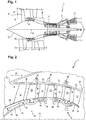
- the figure 1 represents in simplified manner an axial turbomachine. It is in this case a double-flow turbojet engine.
- the turbojet engine 2 comprises a first compression level, called a low-pressure compressor 4, a second compression level, called a high-pressure compressor 6, a combustion chamber 8 and one or more levels of turbines 10.
- the mechanical power the turbine 10 transmitted via the central shaft to the rotor 12 sets in motion the two compressors 4 and 6.
- Reducing means can increase the speed of rotation transmitted to the compressors.
- the different turbine stages can each be connected to the compressor stages via concentric shafts.
- the latter comprise several rows of rotor blades associated with rows of stator vanes. The rotation of the rotor about its axis of rotation 14 thus makes it possible to generate an air flow and to compress it progressively until it reaches the combustion chamber 10.
- a commonly designated fan inlet fan 16 is coupled to the rotor 12 and generates a flow of air which is divided into a primary flow 18 passing through the various levels mentioned above of the turbomachine, and a secondary flow 20 passing through an annular duct (partially shown) along the machine to then join the primary flow at the turbine outlet.
- the primary 18 and secondary 20 streams are annular flows, they are channeled by the casing of the turbomachine.
- the casing has cylindrical walls or ferrules which can be internal and external.
- the figure 2 is a sectional view of a compressor of an axial turbomachine 2 such as that of the figure 1 .
- the compressor may be a low pressure compressor 4.
- the teaching of the present invention may also be applied to a turbine rotor drum 10.
- the rotor 12 comprises several annular rows of rotor blades, in the specific case of the figure 2 three rows are planned. More rows of vanes can be provided. These three rows are axially successive. We observe a first row of rotor blades 24, a second row of rotor blades 26 downstream of the first row 24 and a third row of rotor blades 28 upstream of the first row 24.
- the rotor blades (24, 26, 28) extend substantially radially from the rotor 12.
- the blades of the same row are regularly spaced from each other, and have the same angular orientation in the flow.
- the spacing between the vanes may vary locally, as can their angular orientation. Some blades may be different from the rest of the blades of the corresponding row.
- the compressor 4 comprises an outer casing.
- the outer casing comprises a plurality of rectifiers, for example four, which each comprise an outer shell 30, a row of stator vanes 32 and optionally an inner shell 34.
- An annular layer of abradable material 36 may be applied inside the shell.
- the stator vanes 32 of the same rectifier extend radially from their outer shell 30 to their inner shell 34.
- the rectifiers form circularly closed rings. They are reported axially against each other and fixed to each other by means of radial flanges 38.
- the rectifiers are associated with the fan or a row of rotor vanes (24, 26, 28) for straightening the airflow, so as to convert the speed of the flow into pressure.
- the rotor 12 comprises a drum 40.
- the drum 40 comprises a wall 42 generally symmetrical in revolution about its axis of rotation 14, which axis is common with that of the turbomachine.
- the wall 42 may have a general profile of revolution or average profile of revolution about the axis of rotation 14. The general profile may be included in the thickness of the portions of the wall 42 which are axially right rows of vanes stator.
- the overall profile is essentially curved and may have a continuous curvature and / or a continuous curvature variation. It follows radially the section variation of the inner surface of the primary stream 18.
- the outside of the general profile is convex. From upstream to downstream, the radius of the inner surface increases then decreases, so that the profile of the wall has a peak.
- the wall 42 is essentially thin. Its thickness is generally constant. Its thickness is less than 10.00 mm, preferably less than 5.00 mm, more preferably less than 2.00 mm.
- the wall 42 forms a hollow body which delimits a hollow space, having an ogive or barrel shape.
- the drum 40 and / or the rotor blades (24, 26, 28) are made of metallic materials, preferably of titanium.
- the drum 40 comprises annular ribs 44 or wipers. They form annular lamellae which extend radially. They are intended to cooperate by abrasion with annular layers of abradable material 36 of a rectifier so as to ensure a seal. Generally, one and the same abradable layer 36 cooperates with two annular ribs 44.
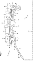
- the figure 3 is detail view in section of the drum 40 of the figure 2 .
- the drum may also be a high pressure compressor rotor drum. It may possibly be a turbine rotor drum.
- the first row of blades 24 is formed on the wall by an annular platform 46.
- the annular platform 46 is integrally formed with the wall 42.
- the annular platform 46 is formed at the top of the profile of the wall 42.
- the annular platform 46 has a profile of revolution generally straight or substantially curved.
- the rotor blades of the second row 26 and the third row 28 each comprise a blade platform 48 defining the inside of the primary flow, a blade 50 extending radially outwardly from the blade platform 46, and a retention foot 52 extending radially inwardly from the blade platform 48.
- the retention foot 52 may have a dovetail shape. It may have a shape whose axial dimension increases when one gets closer to the interior, so as to allow commitment of material.
- the wall 42 of the drum 40 comprises two blade attachment zones by retention groove.
- the attachment zones each comprise an annular groove 54 into which the retention feet 52 of the blades of the second row 26 and the third row 28.
- the annular grooves 54 comprise annular outer surfaces against which the blade platforms 48 come into contact.
- the blade platforms 48 of the second row of blades 26 come into contact with each other. contact of the second outer surface 56, and the blade platforms 48 the third row of blades 28 come into contact with the third outer surface 58.
- the retention feet 52 generally have a shape complementary to the corresponding retention groove, so as to ensure radial retention.
- the retention grooves 54 have a profile with a narrowing at their outlet, to the outside.
- a mechanical clearance is provided between the annular wall 42 and the rotor blades of the second and third rows, so as to allow a slight movement of the blades.
- the rotor is configured so that the centrifugal force present during operation of the plate compressor in position the blades in their groove.
- the retention grooves may be axial grooves.
- the annular wall then comprises an annular row of axial grooves distributed over its circumference, and which each form an annular row of vanes.
- the outer surface (56, 58) of at least one of the annular grooves 48 is at an average distance from the axis 14 which is less than the average distance from the annular platform 46 of the first row 24 of said axis.
- each radius of an axial end of the annular platform 46 is greater than the maximum radius of the outer surface (56, 58) disposed opposite.
- the blades of the first row 24 are anchored to the drum in a different fashion from the other rows (26; 28).
- the retention or fixation of the blades is heterogeneous or hybrid.
- the blades of the first row 24 are fixed by welding on the annular platform 46. They can be friction-welded, for example according to an orbital welding method.
- the drum 40 thus serves as a support for fixing two types of blades.
- blades corresponding to the first row 24 are attached to a raw drum and welded to the annular platform 46. These vanes can be directly or indirectly attached to the annular platform 46.
- the annular platform 46 may include stubs. blades 60 which extend radially from its outer surface. In this case, each blade which is welded to the second surface actually forms only a radial portion of the final blade.
- the weld 62 between a stump and a blade portion is in elevation relative to the annular platform 46.
- the blades of the first row 24 can be integrally machined in the mass of a raw drum in which the wall is also machined.
- the wall of the drum 40 and the blades 24 of the first row form a one-piece assembly. They present a continuity of matter. Their metallic materials have a crystalline continuity at their interface. They can be at least partially come from matter. The anchoring of the vanes is irreversible.
- the blades of the first row 24 are integral with the annular wall 42. This embodiment makes it possible to eliminate vibrations between the blades of the first row 26 and the wall 42 of the drum 40.
- this method of anchoring the blades simplifies the machining to be performed because the annular platform 46 and any stubs 60 are simpler to achieve than an annular groove or several axial grooves. Indeed, a groove must be cut in a generally inaccessible space with a small tool, which lengthens the manufacturing time. Or, an axial groove can be machined by broaching. However, this material removal process requires expensive tooling and is not compatible with all drum shapes.
- the wall 42 of the drum directly upstream and downstream of the first row of blades 24 comprises at least one portion of substantially constant thickness 64 or axial annular junction 64, preferably two portions of substantially constant thicknesses 64.
- Each constant thickness portion 64 extends axially from the annular platform 46 to the second row of blades 26 or to the third row of blades 28.
- the annular platform 46 is radially in annular elevation with respect to each portion of constant thickness 64.
- the portions of constant thicknesses 64 define an annular space between the first row of blades 26 and the second row of blades 28 or the third row of blades 24, these annular spaces being open radially outwardly. They are intended to house internal ferrules of rectifiers.
- the wall 42 comprises two portions 65 which extend generally radially. They extend from the annular platform 46 inwards. They may each be arranged at one of the axial edges of the annular platform 46. In this way, the wall may have a profile of the general Greek letter ⁇ .
- the profiles of the radial portions extend generally perpendicular to the profile of the annular platform 46.
- the annular ribs 44 are arranged on the portions of constant thicknesses 64. Each rib set comprises several ribs 44. On each side of the annular platform 46 there is a gradual decrease in the outer radii from an edge of the annular platform 46, ribs 44, and outer surfaces (56; 58) of the annular grooves. The tops of these elements form a staircase. This configuration makes it possible to report bladed rectifiers on either side of the first row of blades 24, then to assemble the second row 26 and the third row 28.
- the figure 3 illustrates the blades 32 and the inner shroud 36 of the two rectifiers upstream and downstream, respectively, of the first row of blades 24.
- the figure 3 also shows in broken lines these rectifiers in an intermediate position of assembly, in an axial direction, around the drum.
- the annular wall 42 of the drum includes annular stiffeners 66.
- the annular stiffeners 66 may include annular flanges that extend radially inwardly. These flanges are arranged axially at the ends of the annular platform 46, preferably in the radial extension of the radial portions 65.
- the drum is generally machined by turning from a drum-shaped machining blank whose walls encompass the finished drum.
- the rough drum must radially encompass the outer surfaces of the annular grooves 54, the annular platform 46, the internal stiffeners 66, and any blade stubs 60. As the case may be, it may include the blades of the first row 54 over their entire length. radial height.
Landscapes
- Engineering & Computer Science (AREA)
- Mechanical Engineering (AREA)
- General Engineering & Computer Science (AREA)
- Structures Of Non-Positive Displacement Pumps (AREA)
Claims (15)
- Rotortrommel (40) einer axialen Turbomaschine (2), insbesondere eines Niederdruckverdichters (4), wobei die Trommel (40) eine Wand (42) umfasst, die in Drehung um ihre Achse (14) generell symmetrisch ist und ein generell gekrümmtes Profil aufweist, wobei die Wand (42) dafür ausgelegt ist, eine Vielzahl von Schaufelreihen (24, 26, 28) zu tragen;
wobei
eine erste Schaufelreihe (24) durch eine ringförmige Plattform (46) gebildet wird, die einstückig mit der Wand (42) ausgebildet ist, auf dem Scheitel ihres Profils in Bezug zur Achse (14); und mindestens eine, bevorzugt jede, zweite Schaufelreihe (26), direkt stromabwärts von der ersten (24), und dritte Schaufelreihe (28), direkt stromaufwärts von der ersten (24), durch eine oder mehrere an der Wand gebildete Schaufelrückhaltenuten (54) gebildet wird,
dadurch gekennzeichnet, dass
das generell gekrümmte Profil der Wand (42) sich über mehr als die Hälfte der Länge der Trommel erstreckt, wobei das Profil einen maximalen Radius in Höhe der ersten Reihe von Schaufeln (24) aufweist. - Rotortrommel (40) nach Anspruch 1, dadurch gekennzeichnet, dass die Außenflächen (56, 58) der Rückhaltenut oder-nuten (54) sich auf einem durchschnittlichen Abstand von der Achse (14) befindet bzw. befinden, der weniger beträgt als der durchschnittliche Abstand von der Plattform (46) der ersten Reihe (24) zu der besagten Achse.
- Rotortrommel (40) nach einem der Ansprüche 1 und 2, dadurch gekennzeichnet, dass die Wand (42) an ihrer Außenfläche einen Satz ringförmiger Rippen (44) umfasst, die dafür ausgelegt sind, mit einer ringförmigen Schicht von Einlaufmaterial (36) zusammenzuwirken, um eine Abdichtung bereitzustellen, wobei sich der Satz ringförmiger Rippen (44) axial zwischen der ersten (24) und der zweiten (26) Schaufelreihe und/oder zwischen der ersten (24) und der dritten (28) Schaufelreihe befindet.
- Rotortrommel (40) nach Anspruch 3, dadurch gekennzeichnet, dass der Mindestabstand zwischen den Scheiteln eines Satzes von Rippen (44) und der Achse (14) größer ist als der maximale Abstand zwischen der Achse (14) und den Außenflächen (56, 58) der benachbarten Rückhaltenut(en) (54).
- Rotortrommel (40) nach einem der Ansprüche 1 bis 4, dadurch gekennzeichnet, dass die Schaufeln der ersten Schaufelreihe (24) an die Plattform (46) dieser Reihe geschweißt sind.
- Rotortrommel (40) nach einem der Ansprüche 1 bis 4, dadurch gekennzeichnet, dass die Plattform (46) der ersten Schaufelreihe (24) Schaufelstummel (60) beinhaltet, auf die Schaufelerweiterungen geschweißt sind, wobei die Höhe der Schaufelstummel (60) bevorzugt mehr als 10% der radialen Höhe der ersten Schaufelreihe (24), bevorzugter mehr als 25%, darstellt.
- Rotortrommel (40) nach einem der Ansprüche 1 bis 6, dadurch gekennzeichnet, dass die Schaufeln der ersten Schaufelreihe (24) mindestens teilweise in den Körper der unbearbeiteten Trommel geschnitten sind.
- Rotortrommel (40) nach einem der Ansprüche 1 bis 7, dadurch gekennzeichnet, dass das generell gekrümmte Profil der Wand (42) eine Hauptkrümmung aufweist, die zu der Hauptachse gerichtet ist und sich über den Großteil der Länge der Trommel erstreckt.
- Rotortrommel (40) nach einem der Ansprüche 1 bis 8, dadurch gekennzeichnet, dass die Plattform (46) der ersten Schaufelreihe (24) in Bezug zu der Wand direkt stromaufwärts und stromabwärts von der besagten Reihe angehoben ist.
- Rotortrommel (40) nach Anspruch 9, dadurch gekennzeichnet, dass die Wand (42) zwei Teile (65) umfasst, die sich generell radial unter der Plattform (46) der ersten Reihe (24) erstrecken, sodass der Längsschnitt der Wand (42) in Höhe der Plattform (46) ein π-förmiges Profil aufweist.
- Rotortrommel (40) nach Anspruch 10, dadurch gekennzeichnet, dass die Wand (42) mindestens eine ringförmige Versteifung (66) aufweist, die sich auf Höhe der ersten Schaufelreihe (24) radial nach innen erstreckt, bevorzugt in der Verlängerung von mindestens einem der radialen Teile (65).
- Rotortrommel (40) nach einem der Ansprüche 9 bis 11, dadurch gekennzeichnet, dass die Wand (42) unmittelbar stromaufwärts und stromabwärts von der ersten Reihe (24) einen Teil mit im Wesentlichen konstanter Dicke (64) aufweist, der einen ringförmigen Raum zur Aufnahme eines inneren Leitapparat-Deckbandes (34) begrenzt.
- Rotortrommel (40) nach einem der Ansprüche 1 bis 12, dadurch gekennzeichnet, dass sie Schaufeln der zweiten und/oder dritten Schaufelreihe umfasst, wovon jede der besagten Schaufeln einen Schaufelfuß (52) umfasst, der in der, oder einer, Rückhaltenut (54) sitzt.
- Rotortrommel (40) nach einem der Ansprüche 1 bis 13, dadurch gekennzeichnet, dass die Rückhaltenut(en) (54) entlang dem Umfang der Trommel (40) ringförmig ist bzw. sind.
- Axiale Turbomaschine (2), umfassend eine Rotortrommel (40), dadurch gekennzeichnet, dass die Trommel (40) einem der Ansprüche 1 bis 14 entspricht, wobei der Rotor (12) bevorzugt ein Niederdruckverdichterrotor (4) ist, der im Wesentlichen drei ringförmige Reihen von Rotorschaufeln (24, 26, 28) umfasst.
Priority Applications (5)
| Application Number | Priority Date | Filing Date | Title |
|---|---|---|---|
| EP13173510.2A EP2818635B1 (de) | 2013-06-25 | 2013-06-25 | Kompressortrommel einer axialen Turbomaschine mit gemischter Befestigung der Laufradschaufeln |
| CA2853663A CA2853663A1 (en) | 2013-06-25 | 2014-06-09 | Axial turbomachine compressor drum with dual means of blade fixing |
| RU2014125101/02A RU2576354C2 (ru) | 2013-06-25 | 2014-06-20 | Барабан компрессора осевой турбомашины с двойным средством для фиксации лопаток |
| US14/315,097 US20140377070A1 (en) | 2013-06-25 | 2014-06-25 | Axial Turbomachine Compressor Drum with Dual Means of Blade Fixing |
| CN201410290159.1A CN104251232B (zh) | 2013-06-25 | 2014-06-25 | 具有双重叶片固定方式的轴流式涡轮机压缩机鼓轮 |
Applications Claiming Priority (1)
| Application Number | Priority Date | Filing Date | Title |
|---|---|---|---|
| EP13173510.2A EP2818635B1 (de) | 2013-06-25 | 2013-06-25 | Kompressortrommel einer axialen Turbomaschine mit gemischter Befestigung der Laufradschaufeln |
Publications (2)
| Publication Number | Publication Date |
|---|---|
| EP2818635A1 EP2818635A1 (de) | 2014-12-31 |
| EP2818635B1 true EP2818635B1 (de) | 2019-04-10 |
Family
ID=48703179
Family Applications (1)
| Application Number | Title | Priority Date | Filing Date |
|---|---|---|---|
| EP13173510.2A Active EP2818635B1 (de) | 2013-06-25 | 2013-06-25 | Kompressortrommel einer axialen Turbomaschine mit gemischter Befestigung der Laufradschaufeln |
Country Status (5)
| Country | Link |
|---|---|
| US (1) | US20140377070A1 (de) |
| EP (1) | EP2818635B1 (de) |
| CN (1) | CN104251232B (de) |
| CA (1) | CA2853663A1 (de) |
| RU (1) | RU2576354C2 (de) |
Families Citing this family (6)
| Publication number | Priority date | Publication date | Assignee | Title |
|---|---|---|---|---|
| EP2801702B1 (de) * | 2013-05-10 | 2020-05-06 | Safran Aero Boosters SA | Stator-innenring eines turbotriebwerks mit abriebmaterial |
| EP3273003B1 (de) * | 2014-07-07 | 2023-09-06 | Safran Aero Boosters SA | Leitschaufelsegment eines verdichters eines axialen turbotriebwerks |
| GB201502612D0 (en) | 2015-02-17 | 2015-04-01 | Rolls Royce Plc | Rotor disc |
| BE1027025B1 (fr) | 2019-02-04 | 2020-09-02 | Safran Aero Boosters Sa | Rotor hybride à tambour segmenté |
| BE1027190B1 (fr) | 2019-04-15 | 2020-11-16 | Safran Aero Boosters Sa | Rotor hybride avec inserts |
| IT201900014724A1 (it) * | 2019-08-13 | 2021-02-13 | Ge Avio Srl | Elementi di trattenimento delle pale per turbomacchine. |
Citations (1)
| Publication number | Priority date | Publication date | Assignee | Title |
|---|---|---|---|---|
| US8087884B2 (en) * | 2006-11-30 | 2012-01-03 | General Electric Company | Advanced booster stator vane |
Family Cites Families (10)
| Publication number | Priority date | Publication date | Assignee | Title |
|---|---|---|---|---|
| SU1262061A1 (ru) * | 1985-02-26 | 1986-10-07 | Всесоюзный научно-исследовательский и конструкторско-технологический институт компрессорного машиностроения | Ротор осевого компрессора |
| FR2845436B1 (fr) | 2002-10-02 | 2004-12-31 | Snecma Moteurs | Tambour formant en particulier un rotor de turbomachine, compresseur et turbomoteur comprenant un tel tambour |
| US8516674B2 (en) * | 2003-11-14 | 2013-08-27 | General Electric Company | Solid state resistance welding for airfoil repair and manufacture |
| US7144221B2 (en) * | 2004-07-30 | 2006-12-05 | General Electric Company | Method and apparatus for assembling gas turbine engines |
| DE102005042272A1 (de) | 2005-09-06 | 2007-03-08 | Mtu Aero Engines Gmbh | Strömungsmaschine sowie Dichtungselement für eine Strömungsmaschine |
| DE102006015838A1 (de) * | 2006-04-03 | 2007-10-04 | Rolls-Royce Deutschland Ltd & Co Kg | Axialkompressor für ein Gasturbinentriebwerk |
| US8317481B2 (en) * | 2008-02-22 | 2012-11-27 | General Electric Company | Rotor of a turbomachine and method for replacing rotor blades of the rotor |
| EP2369136B1 (de) * | 2010-03-12 | 2012-12-19 | Techspace Aero S.A. | Gewichtsreduzierte einteilige Mehrstufentrommel eines Axialverdichters |
| EP2505789B1 (de) * | 2011-03-30 | 2016-12-28 | Safran Aero Boosters SA | Gasflussabscheider mit Enteisungsvorrichtung über Wärmebrücke |
| US8840374B2 (en) * | 2011-10-12 | 2014-09-23 | General Electric Company | Adaptor assembly for coupling turbine blades to rotor disks |
-
2013
- 2013-06-25 EP EP13173510.2A patent/EP2818635B1/de active Active
-
2014
- 2014-06-09 CA CA2853663A patent/CA2853663A1/en not_active Abandoned
- 2014-06-20 RU RU2014125101/02A patent/RU2576354C2/ru active
- 2014-06-25 US US14/315,097 patent/US20140377070A1/en not_active Abandoned
- 2014-06-25 CN CN201410290159.1A patent/CN104251232B/zh active Active
Patent Citations (1)
| Publication number | Priority date | Publication date | Assignee | Title |
|---|---|---|---|---|
| US8087884B2 (en) * | 2006-11-30 | 2012-01-03 | General Electric Company | Advanced booster stator vane |
Also Published As
| Publication number | Publication date |
|---|---|
| CA2853663A1 (en) | 2014-12-25 |
| US20140377070A1 (en) | 2014-12-25 |
| CN104251232B (zh) | 2019-04-30 |
| EP2818635A1 (de) | 2014-12-31 |
| RU2014125101A (ru) | 2015-12-27 |
| RU2576354C2 (ru) | 2016-02-27 |
| CN104251232A (zh) | 2014-12-31 |
Similar Documents
| Publication | Publication Date | Title |
|---|---|---|
| EP2818635B1 (de) | Kompressortrommel einer axialen Turbomaschine mit gemischter Befestigung der Laufradschaufeln | |
| EP2801702B1 (de) | Stator-innenring eines turbotriebwerks mit abriebmaterial | |
| EP2937517B1 (de) | Stator einer axialen Turbomaschine und zugehörige Turbomaschine | |
| EP2204541B1 (de) | Rotorstufe einer einteilig beschaufelten Verdichtertrommel einer axialen Strömungsmaschine und entsprechendes Herstellungsverfahren. | |
| EP2977549B1 (de) | Beschaufelung einer axialen strömungsmaschine und zugehörige turbomachine | |
| EP3109406B1 (de) | Gehäuse für kompressor eines axialen turbotriebwerks | |
| EP2843196B1 (de) | Verdichter einer turbomaschine und zugehörige turbomaschine | |
| EP3521569B1 (de) | Strukturgehäuse für axiale turbomaschine | |
| EP2795068B1 (de) | Leitschaufelanordnung eines turbomaschinenverdichters | |
| EP3409902B1 (de) | Abdichtungssystem für kompressor einer strömungsmaschine | |
| EP2821595B1 (de) | Statorschaufelabschnitt mit abwechselnden befestigungen für eine axiale turbomaschine | |
| EP2762681B1 (de) | Rotortrommel einer axialen Turbomaschine und zugehörige Turbomaschine | |
| EP2937516A1 (de) | Rundgebogenes Monoblock-Gehäuse für Kompressor einer axialen Turbomaschine und entsprechendes Fertigungsverfahren | |
| WO2016015980A1 (fr) | Procede de realisation d'un stator de compresseur de turbomachine axiale | |
| EP3382242B1 (de) | Bürstendichtung für rotor einer turbomaschine | |
| EP3690192A1 (de) | Hybrid-rotor mit segmentierter trommel | |
| BE1025131B1 (fr) | Arbre de transmission à double cannelure pour turbomachine | |
| BE1030042B1 (fr) | Roue mobile a anneau intermediaire | |
| EP3715638B1 (de) | Hybridrotor mit einem aussenmantel, der an der ringgförmigen verbundwand anliegt | |
| EP3477052A1 (de) | Nicht-axialsymmetrisches profil eines gehäuses für einen kompressor eines gasturbinenmotors | |
| BE1022882A9 (fr) | Tournage a choc d'extremites d'aubes de blum de compresseur de turbomachine axiale | |
| BE1023397B1 (fr) | Aube a calage variable de compresseur de turbomachine axiale | |
| EP2977550A1 (de) | Verdichterschaufel einer axialen Strömungsmaschine mit Verzweigungen an dem inneren und äusseren Ende |
Legal Events
| Date | Code | Title | Description |
|---|---|---|---|
| PUAI | Public reference made under article 153(3) epc to a published international application that has entered the european phase |
Free format text: ORIGINAL CODE: 0009012 |
|
| 17P | Request for examination filed |
Effective date: 20130625 |
|
| AK | Designated contracting states |
Kind code of ref document: A1 Designated state(s): AL AT BE BG CH CY CZ DE DK EE ES FI FR GB GR HR HU IE IS IT LI LT LU LV MC MK MT NL NO PL PT RO RS SE SI SK SM TR |
|
| AX | Request for extension of the european patent |
Extension state: BA ME |
|
| R17P | Request for examination filed (corrected) |
Effective date: 20150630 |
|
| RBV | Designated contracting states (corrected) |
Designated state(s): AL AT BE BG CH CY CZ DE DK EE ES FI FR GB GR HR HU IE IS IT LI LT LU LV MC MK MT NL NO PL PT RO RS SE SI SK SM TR |
|
| RAP1 | Party data changed (applicant data changed or rights of an application transferred) |
Owner name: SAFRAN AERO BOOSTERS SA |
|
| STAA | Information on the status of an ep patent application or granted ep patent |
Free format text: STATUS: EXAMINATION IS IN PROGRESS |
|
| 17Q | First examination report despatched |
Effective date: 20170821 |
|
| GRAP | Despatch of communication of intention to grant a patent |
Free format text: ORIGINAL CODE: EPIDOSNIGR1 |
|
| STAA | Information on the status of an ep patent application or granted ep patent |
Free format text: STATUS: GRANT OF PATENT IS INTENDED |
|
| INTG | Intention to grant announced |
Effective date: 20181016 |
|
| GRAS | Grant fee paid |
Free format text: ORIGINAL CODE: EPIDOSNIGR3 |
|
| GRAA | (expected) grant |
Free format text: ORIGINAL CODE: 0009210 |
|
| STAA | Information on the status of an ep patent application or granted ep patent |
Free format text: STATUS: THE PATENT HAS BEEN GRANTED |
|
| AK | Designated contracting states |
Kind code of ref document: B1 Designated state(s): AL AT BE BG CH CY CZ DE DK EE ES FI FR GB GR HR HU IE IS IT LI LT LU LV MC MK MT NL NO PL PT RO RS SE SI SK SM TR |
|
| REG | Reference to a national code |
Ref country code: GB Ref legal event code: FG4D Free format text: NOT ENGLISH |
|
| REG | Reference to a national code |
Ref country code: CH Ref legal event code: EP Ref country code: AT Ref legal event code: REF Ref document number: 1118896 Country of ref document: AT Kind code of ref document: T Effective date: 20190415 |
|
| REG | Reference to a national code |
Ref country code: DE Ref legal event code: R096 Ref document number: 602013053559 Country of ref document: DE |
|
| REG | Reference to a national code |
Ref country code: IE Ref legal event code: FG4D Free format text: LANGUAGE OF EP DOCUMENT: FRENCH |
|
| REG | Reference to a national code |
Ref country code: NL Ref legal event code: MP Effective date: 20190410 |
|
| REG | Reference to a national code |
Ref country code: LT Ref legal event code: MG4D |
|
| REG | Reference to a national code |
Ref country code: AT Ref legal event code: MK05 Ref document number: 1118896 Country of ref document: AT Kind code of ref document: T Effective date: 20190410 |
|
| PG25 | Lapsed in a contracting state [announced via postgrant information from national office to epo] |
Ref country code: NL Free format text: LAPSE BECAUSE OF FAILURE TO SUBMIT A TRANSLATION OF THE DESCRIPTION OR TO PAY THE FEE WITHIN THE PRESCRIBED TIME-LIMIT Effective date: 20190410 |
|
| PG25 | Lapsed in a contracting state [announced via postgrant information from national office to epo] |
Ref country code: SE Free format text: LAPSE BECAUSE OF FAILURE TO SUBMIT A TRANSLATION OF THE DESCRIPTION OR TO PAY THE FEE WITHIN THE PRESCRIBED TIME-LIMIT Effective date: 20190410 Ref country code: PT Free format text: LAPSE BECAUSE OF FAILURE TO SUBMIT A TRANSLATION OF THE DESCRIPTION OR TO PAY THE FEE WITHIN THE PRESCRIBED TIME-LIMIT Effective date: 20190910 Ref country code: HR Free format text: LAPSE BECAUSE OF FAILURE TO SUBMIT A TRANSLATION OF THE DESCRIPTION OR TO PAY THE FEE WITHIN THE PRESCRIBED TIME-LIMIT Effective date: 20190410 Ref country code: AL Free format text: LAPSE BECAUSE OF FAILURE TO SUBMIT A TRANSLATION OF THE DESCRIPTION OR TO PAY THE FEE WITHIN THE PRESCRIBED TIME-LIMIT Effective date: 20190410 Ref country code: NO Free format text: LAPSE BECAUSE OF FAILURE TO SUBMIT A TRANSLATION OF THE DESCRIPTION OR TO PAY THE FEE WITHIN THE PRESCRIBED TIME-LIMIT Effective date: 20190710 Ref country code: FI Free format text: LAPSE BECAUSE OF FAILURE TO SUBMIT A TRANSLATION OF THE DESCRIPTION OR TO PAY THE FEE WITHIN THE PRESCRIBED TIME-LIMIT Effective date: 20190410 Ref country code: LT Free format text: LAPSE BECAUSE OF FAILURE TO SUBMIT A TRANSLATION OF THE DESCRIPTION OR TO PAY THE FEE WITHIN THE PRESCRIBED TIME-LIMIT Effective date: 20190410 Ref country code: ES Free format text: LAPSE BECAUSE OF FAILURE TO SUBMIT A TRANSLATION OF THE DESCRIPTION OR TO PAY THE FEE WITHIN THE PRESCRIBED TIME-LIMIT Effective date: 20190410 |
|
| PG25 | Lapsed in a contracting state [announced via postgrant information from national office to epo] |
Ref country code: GR Free format text: LAPSE BECAUSE OF FAILURE TO SUBMIT A TRANSLATION OF THE DESCRIPTION OR TO PAY THE FEE WITHIN THE PRESCRIBED TIME-LIMIT Effective date: 20190711 Ref country code: BG Free format text: LAPSE BECAUSE OF FAILURE TO SUBMIT A TRANSLATION OF THE DESCRIPTION OR TO PAY THE FEE WITHIN THE PRESCRIBED TIME-LIMIT Effective date: 20190710 Ref country code: RS Free format text: LAPSE BECAUSE OF FAILURE TO SUBMIT A TRANSLATION OF THE DESCRIPTION OR TO PAY THE FEE WITHIN THE PRESCRIBED TIME-LIMIT Effective date: 20190410 Ref country code: PL Free format text: LAPSE BECAUSE OF FAILURE TO SUBMIT A TRANSLATION OF THE DESCRIPTION OR TO PAY THE FEE WITHIN THE PRESCRIBED TIME-LIMIT Effective date: 20190410 Ref country code: LV Free format text: LAPSE BECAUSE OF FAILURE TO SUBMIT A TRANSLATION OF THE DESCRIPTION OR TO PAY THE FEE WITHIN THE PRESCRIBED TIME-LIMIT Effective date: 20190410 |
|
| PG25 | Lapsed in a contracting state [announced via postgrant information from national office to epo] |
Ref country code: AT Free format text: LAPSE BECAUSE OF FAILURE TO SUBMIT A TRANSLATION OF THE DESCRIPTION OR TO PAY THE FEE WITHIN THE PRESCRIBED TIME-LIMIT Effective date: 20190410 Ref country code: IS Free format text: LAPSE BECAUSE OF FAILURE TO SUBMIT A TRANSLATION OF THE DESCRIPTION OR TO PAY THE FEE WITHIN THE PRESCRIBED TIME-LIMIT Effective date: 20190810 |
|
| REG | Reference to a national code |
Ref country code: DE Ref legal event code: R097 Ref document number: 602013053559 Country of ref document: DE |
|
| PG25 | Lapsed in a contracting state [announced via postgrant information from national office to epo] |
Ref country code: DK Free format text: LAPSE BECAUSE OF FAILURE TO SUBMIT A TRANSLATION OF THE DESCRIPTION OR TO PAY THE FEE WITHIN THE PRESCRIBED TIME-LIMIT Effective date: 20190410 Ref country code: EE Free format text: LAPSE BECAUSE OF FAILURE TO SUBMIT A TRANSLATION OF THE DESCRIPTION OR TO PAY THE FEE WITHIN THE PRESCRIBED TIME-LIMIT Effective date: 20190410 Ref country code: RO Free format text: LAPSE BECAUSE OF FAILURE TO SUBMIT A TRANSLATION OF THE DESCRIPTION OR TO PAY THE FEE WITHIN THE PRESCRIBED TIME-LIMIT Effective date: 20190410 Ref country code: CZ Free format text: LAPSE BECAUSE OF FAILURE TO SUBMIT A TRANSLATION OF THE DESCRIPTION OR TO PAY THE FEE WITHIN THE PRESCRIBED TIME-LIMIT Effective date: 20190410 Ref country code: SK Free format text: LAPSE BECAUSE OF FAILURE TO SUBMIT A TRANSLATION OF THE DESCRIPTION OR TO PAY THE FEE WITHIN THE PRESCRIBED TIME-LIMIT Effective date: 20190410 Ref country code: MC Free format text: LAPSE BECAUSE OF FAILURE TO SUBMIT A TRANSLATION OF THE DESCRIPTION OR TO PAY THE FEE WITHIN THE PRESCRIBED TIME-LIMIT Effective date: 20190410 |
|
| REG | Reference to a national code |
Ref country code: CH Ref legal event code: PL |
|
| PLBE | No opposition filed within time limit |
Free format text: ORIGINAL CODE: 0009261 |
|
| STAA | Information on the status of an ep patent application or granted ep patent |
Free format text: STATUS: NO OPPOSITION FILED WITHIN TIME LIMIT |
|
| PG25 | Lapsed in a contracting state [announced via postgrant information from national office to epo] |
Ref country code: SM Free format text: LAPSE BECAUSE OF FAILURE TO SUBMIT A TRANSLATION OF THE DESCRIPTION OR TO PAY THE FEE WITHIN THE PRESCRIBED TIME-LIMIT Effective date: 20190410 Ref country code: IT Free format text: LAPSE BECAUSE OF FAILURE TO SUBMIT A TRANSLATION OF THE DESCRIPTION OR TO PAY THE FEE WITHIN THE PRESCRIBED TIME-LIMIT Effective date: 20190410 |
|
| 26N | No opposition filed |
Effective date: 20200113 |
|
| PG25 | Lapsed in a contracting state [announced via postgrant information from national office to epo] |
Ref country code: TR Free format text: LAPSE BECAUSE OF FAILURE TO SUBMIT A TRANSLATION OF THE DESCRIPTION OR TO PAY THE FEE WITHIN THE PRESCRIBED TIME-LIMIT Effective date: 20190410 |
|
| PG25 | Lapsed in a contracting state [announced via postgrant information from national office to epo] |
Ref country code: IE Free format text: LAPSE BECAUSE OF NON-PAYMENT OF DUE FEES Effective date: 20190625 |
|
| PG25 | Lapsed in a contracting state [announced via postgrant information from national office to epo] |
Ref country code: LI Free format text: LAPSE BECAUSE OF NON-PAYMENT OF DUE FEES Effective date: 20190630 Ref country code: CH Free format text: LAPSE BECAUSE OF NON-PAYMENT OF DUE FEES Effective date: 20190630 Ref country code: SI Free format text: LAPSE BECAUSE OF FAILURE TO SUBMIT A TRANSLATION OF THE DESCRIPTION OR TO PAY THE FEE WITHIN THE PRESCRIBED TIME-LIMIT Effective date: 20190410 Ref country code: LU Free format text: LAPSE BECAUSE OF NON-PAYMENT OF DUE FEES Effective date: 20190625 |
|
| PG25 | Lapsed in a contracting state [announced via postgrant information from national office to epo] |
Ref country code: CY Free format text: LAPSE BECAUSE OF FAILURE TO SUBMIT A TRANSLATION OF THE DESCRIPTION OR TO PAY THE FEE WITHIN THE PRESCRIBED TIME-LIMIT Effective date: 20190410 |
|
| PG25 | Lapsed in a contracting state [announced via postgrant information from national office to epo] |
Ref country code: HU Free format text: LAPSE BECAUSE OF FAILURE TO SUBMIT A TRANSLATION OF THE DESCRIPTION OR TO PAY THE FEE WITHIN THE PRESCRIBED TIME-LIMIT; INVALID AB INITIO Effective date: 20130625 Ref country code: MT Free format text: LAPSE BECAUSE OF FAILURE TO SUBMIT A TRANSLATION OF THE DESCRIPTION OR TO PAY THE FEE WITHIN THE PRESCRIBED TIME-LIMIT Effective date: 20190410 |
|
| PG25 | Lapsed in a contracting state [announced via postgrant information from national office to epo] |
Ref country code: MK Free format text: LAPSE BECAUSE OF FAILURE TO SUBMIT A TRANSLATION OF THE DESCRIPTION OR TO PAY THE FEE WITHIN THE PRESCRIBED TIME-LIMIT Effective date: 20190410 |
|
| PGFP | Annual fee paid to national office [announced via postgrant information from national office to epo] |
Ref country code: DE Payment date: 20250618 Year of fee payment: 13 |
|
| PGFP | Annual fee paid to national office [announced via postgrant information from national office to epo] |
Ref country code: GB Payment date: 20250625 Year of fee payment: 13 |
|
| PGFP | Annual fee paid to national office [announced via postgrant information from national office to epo] |
Ref country code: BE Payment date: 20250624 Year of fee payment: 13 |
|
| PGFP | Annual fee paid to national office [announced via postgrant information from national office to epo] |
Ref country code: FR Payment date: 20250623 Year of fee payment: 13 |