EP2818628A2 - Monitoring a hydraulic fluid filter - Google Patents
Monitoring a hydraulic fluid filter Download PDFInfo
- Publication number
- EP2818628A2 EP2818628A2 EP14174044.9A EP14174044A EP2818628A2 EP 2818628 A2 EP2818628 A2 EP 2818628A2 EP 14174044 A EP14174044 A EP 14174044A EP 2818628 A2 EP2818628 A2 EP 2818628A2
- Authority
- EP
- European Patent Office
- Prior art keywords
- hydraulic fluid
- filter
- subsea
- input
- control module
- Prior art date
- Legal status (The legal status is an assumption and is not a legal conclusion. Google has not performed a legal analysis and makes no representation as to the accuracy of the status listed.)
- Granted
Links
Images


Classifications
-
- G—PHYSICS
- G01—MEASURING; TESTING
- G01N—INVESTIGATING OR ANALYSING MATERIALS BY DETERMINING THEIR CHEMICAL OR PHYSICAL PROPERTIES
- G01N15/00—Investigating characteristics of particles; Investigating permeability, pore-volume or surface-area of porous materials
- G01N15/08—Investigating permeability, pore-volume, or surface area of porous materials
- G01N15/082—Investigating permeability by forcing a fluid through a sample
- G01N15/0826—Investigating permeability by forcing a fluid through a sample and measuring fluid flow rate, i.e. permeation rate or pressure change
-
- B—PERFORMING OPERATIONS; TRANSPORTING
- B01—PHYSICAL OR CHEMICAL PROCESSES OR APPARATUS IN GENERAL
- B01D—SEPARATION
- B01D35/00—Filtering devices having features not specifically covered by groups B01D24/00 - B01D33/00, or for applications not specifically covered by groups B01D24/00 - B01D33/00; Auxiliary devices for filtration; Filter housing constructions
- B01D35/14—Safety devices specially adapted for filtration; Devices for indicating clogging
- B01D35/143—Filter condition indicators
-
- E—FIXED CONSTRUCTIONS
- E21—EARTH OR ROCK DRILLING; MINING
- E21B—EARTH OR ROCK DRILLING; OBTAINING OIL, GAS, WATER, SOLUBLE OR MELTABLE MATERIALS OR A SLURRY OF MINERALS FROM WELLS
- E21B33/00—Sealing or packing boreholes or wells
- E21B33/02—Surface sealing or packing
- E21B33/03—Well heads; Setting-up thereof
- E21B33/035—Well heads; Setting-up thereof specially adapted for underwater installations
- E21B33/0355—Control systems, e.g. hydraulic, pneumatic, electric, acoustic, for submerged well heads
-
- E—FIXED CONSTRUCTIONS
- E21—EARTH OR ROCK DRILLING; MINING
- E21B—EARTH OR ROCK DRILLING; OBTAINING OIL, GAS, WATER, SOLUBLE OR MELTABLE MATERIALS OR A SLURRY OF MINERALS FROM WELLS
- E21B47/00—Survey of boreholes or wells
- E21B47/06—Measuring temperature or pressure
-
- F—MECHANICAL ENGINEERING; LIGHTING; HEATING; WEAPONS; BLASTING
- F15—FLUID-PRESSURE ACTUATORS; HYDRAULICS OR PNEUMATICS IN GENERAL
- F15B—SYSTEMS ACTING BY MEANS OF FLUIDS IN GENERAL; FLUID-PRESSURE ACTUATORS, e.g. SERVOMOTORS; DETAILS OF FLUID-PRESSURE SYSTEMS, NOT OTHERWISE PROVIDED FOR
- F15B21/00—Common features of fluid actuator systems; Fluid-pressure actuator systems or details thereof, not covered by any other group of this subclass
- F15B21/04—Special measures taken in connection with the properties of the fluid
- F15B21/041—Removal or measurement of solid or liquid contamination, e.g. filtering
-
- G—PHYSICS
- G01—MEASURING; TESTING
- G01N—INVESTIGATING OR ANALYSING MATERIALS BY DETERMINING THEIR CHEMICAL OR PHYSICAL PROPERTIES
- G01N15/00—Investigating characteristics of particles; Investigating permeability, pore-volume or surface-area of porous materials
- G01N15/08—Investigating permeability, pore-volume, or surface area of porous materials
- G01N2015/084—Testing filters
Definitions
- This invention relates to monitoring a hydraulic fluid filter, in particular such a filter in an underwater (for example subsea) well control system.
- the main equipment of a typical system configuration includes:
- Hydraulic fluid is supplied to a subsea control module in a redundant manner in order to provide power for operating the hydraulic valves located on subsea trees and manifolds.
- the fluid In order to remove particulate matter from the fluid, the fluid is passed through filters. Pressure transducers are normally located downstream of the filters for monitoring the incoming pressure of the fluid, and then selector valves allow the operator to select which of the redundant supplies is used for valve operation. The selected fluid is then used as a common supply for operations within the subsea control module, and a pressure transducer is used to monitor this supply pressure.
- Fig. 1 shows a typical schematic for one of the supplies to a subsea control module.
- Hydraulic fluid is supplied in a redundant manner from supplies A and B via inputs 1 a and 1b and each incoming supply is filtered to remove particulate matter by a respective one of filters 2a and 2b. Then the fluid is passed to respective ones of selector valves 4a and 4b, enabling supply selection to be performed, and a common supply to an output 5 is provided via a shuttle valve 6.
- the pressure of hydraulic fluid downstream of the filters is monitored by respective ones of pressure transducers 7a and 7b and the pressure of the common supply is monitored downstream of the shuttle valve 6 by a pressure transducer 8.
- the common supply from output 5 is fed to a manifold 9 within the subsea control module.
- a hydraulic circuit for supplying hydraulic fluid to a subsea control module of a control system for an underwater hydrocarbon well comprising:
- the circuit includes:
- the first and further such first sensing means could comprise respective ones of transducers between the first and further filters and the first and further inputs.
- the second sensing means could comprise a transducer between such selecting means and the output.
- the second sensing means could comprise respective ones of transducers between outputs of the first and further filters and such selecting means.
- a method of monitoring a filter in a hydraulic circuit for supplying hydraulic fluid to a subsea control module of a control system for an underwater hydrocarbon well comprising: an input for hydraulic fluid; a filter connected to the input for filtering hydraulic fluid from the input; and an output for supplying hydraulic fluid from the filter to the subsea control module, wherein the method comprises:
- the circuit includes a further input for hydraulic fluid and a further filter, connected to the further input for filtering hydraulic fluid from the further input, the output being connected for use in supplying hydraulic fluid from the further filter to the subsea control module, the method comprising:
- pressure transducers 7a and 7b have been omitted, the input supplies of filters 2a and 2b are monitored by respective ones of upstream pressure transducers 10a and 10b, and transducer 8 and transducers 10a and 10b are coupled with a subsea electronics module (SEM) 11 in the subsea control module.
- SEM subsea electronics module
- Filter health monitoring using differential pressure sensing is known using a dedicated physical differential pressure sensor across the filter.
- this application uses normal pressure transducers which can exist in the circuit, and software algorithms in the subsea electronics module to implement an active monitoring system.
- the subsea electronics module software is configured to monitor the hydraulic pressure transducer 8 downstream of the shuttle valve and the hydraulic pressure transducer 10a or 10b upstream of the filter synchronously so that their digitised signals represent the pressures at the same point in time. By then subtracting the downstream pressure from the upstream pressure, a virtual differential pressure sensor is realised.
- the differential pressure function is calculated through software, other calibration factors may be applied such as correcting for incoming supply pressure fluctuations.
- Fig. 2 there are other components than filters in the flow path between each input and the output (selector valves and shuttle valve). These components may affect flow, and as such affect the differential pressure measured. However these devices can be considered constants, and their effect zeroed out of the calculated differential pressure through taking baseline readings when the filter is known to be clean.
- FIG. 3 A further improvement of the hydraulic circuit (at the expense of additional pressure transducers) may be realised as shown in Fig. 3 , in which items which correspond with those in Figs. 1 and 2 have the same reference numerals as in Figs. 1 and 2 .
- transducers 7a or 7b are included, the subsea electronics module 11 monitoring the pressure differential between transducer 7a or 7b and transducer 10a or 10b as the case may be, depending on which of filters 2a and 2b is supplying hydraulic fluid to the output 5.
- This configuration allows absolute monitoring of the filters without the potential for differential pressure inaccuracy due to the other components in the flow path.
- At least one further such subsea electronics module 12 could be included in the subsea control module for redundancy purposes, one of them being used as appropriate.
- the or each further module 12 is coupled with transducers 8 and 10a and 10b in the case of Fig. 2 and with transducers 7a and 7b and 10a and 10b in the case of Fig. 3 .
- the invention enables the contamination levels of the filters within a subsea control module to be assessed whilst the module is in operation, enables the operator to be alerted of contamination, and enables maintenance of the module to be scheduled
- subsea control module operation may be optimised, or preventative maintenance planned thus alleviating unscheduled shutdowns and loss of production.
Landscapes
- Engineering & Computer Science (AREA)
- Life Sciences & Earth Sciences (AREA)
- Geology (AREA)
- Mining & Mineral Resources (AREA)
- Physics & Mathematics (AREA)
- Fluid Mechanics (AREA)
- Environmental & Geological Engineering (AREA)
- General Life Sciences & Earth Sciences (AREA)
- Geochemistry & Mineralogy (AREA)
- Chemical & Material Sciences (AREA)
- Geophysics (AREA)
- Analytical Chemistry (AREA)
- Dispersion Chemistry (AREA)
- Health & Medical Sciences (AREA)
- Biochemistry (AREA)
- General Health & Medical Sciences (AREA)
- General Physics & Mathematics (AREA)
- Immunology (AREA)
- Pathology (AREA)
- General Engineering & Computer Science (AREA)
- Chemical Kinetics & Catalysis (AREA)
- Mechanical Engineering (AREA)
- Fluid-Pressure Circuits (AREA)
Abstract
Description
- This invention relates to monitoring a hydraulic fluid filter, in particular such a filter in an underwater (for example subsea) well control system.
- In offshore hydrocarbon well control systems, the main equipment of a typical system configuration includes:
- a master control station, which provides the operator interface with subsea equipment and displays the current state of various subsurface equipment, subsea valves and sensor information enabling the operator to control the system;
- an umbilical cable, which connects the master control station to the equipment installed on the seabed and incorporates a communication link which carries control signals to the subsurface equipment and transfers information on the status of the subsurface equipment to the master control station;
- a subsea control module, which receives commands from the master control station and controls subsea processes, provides the hydraulic power to actuate valves and transmits status data on subsea equipment and sensor data to the master control station;
- a subsea electronics module, housed within the subsea control module and which typically is a microprocessor based electronics unit that houses a set of printed circuit boards, the functions of which include communication with the master control station (receiving control information from, and transmitting sensor data to, the master control station), interfacing with subsurface sensors and controlling valves and hydraulics; and
- a tree installed on the seabed, to which is fitted the subsurface electric and hydraulic equipment needed to control the flow of fluids from or to the well together with a sensor pack, to determine the state of the tree equipment, well head components and fluid flowing from or to the well.
- Hydraulic fluid is supplied to a subsea control module in a redundant manner in order to provide power for operating the hydraulic valves located on subsea trees and manifolds.
- In order to remove particulate matter from the fluid, the fluid is passed through filters. Pressure transducers are normally located downstream of the filters for monitoring the incoming pressure of the fluid, and then selector valves allow the operator to select which of the redundant supplies is used for valve operation. The selected fluid is then used as a common supply for operations within the subsea control module, and a pressure transducer is used to monitor this supply pressure.
-
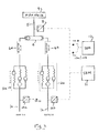
Fig. 1 shows a typical schematic for one of the supplies to a subsea control module. Hydraulic fluid is supplied in a redundant manner from supplies A and B viainputs 1 a and 1b and each incoming supply is filtered to remove particulate matter by a respective one offilters selector valves 4a and 4b, enabling supply selection to be performed, and a common supply to anoutput 5 is provided via a shuttle valve 6. The pressure of hydraulic fluid downstream of the filters is monitored by respective ones of pressure transducers 7a and 7b and the pressure of the common supply is monitored downstream of the shuttle valve 6 by apressure transducer 8. The common supply fromoutput 5 is fed to amanifold 9 within the subsea control module. - With this configuration of transducers and filters, there is no method to monitor the health (contamination levels) and hence life of the filters.
- If there is no method for assessing the contamination of such filters when a subsea control module is deployed and the subsea control module is operated until problems are experienced, if the filters become blocked, this could result in the well being shut in, and cause lack of hydrocarbon production for a period of time until the module can be recovered and a replacement installed.
- According to this invention from one aspect, there is provided a hydraulic circuit for supplying hydraulic fluid to a subsea control module of a control system for an underwater hydrocarbon well, comprising:
- an input for hydraulic fluid;
- a filter connected to the input for filtering hydraulic fluid from the input;
- an output for supplying hydraulic fluid from the filter to the subsea control module;
- first sensing means for sensing pressure of hydraulic fluid from the input upstream of the filter;
- second sensing means for sensing pressure of hydraulic fluid downstream of the filter; and
- a subsea electronics module in the subsea control module, the subsea electronics module being coupled with the first and second sensing means and being adapted to produce an indication related to a hydraulic fluid pressure differential across the filter.
- There could be at least one further such subsea electronics module in the subsea control module for redundancy purposes, the or each further subsea electronics module also being coupled with the first and second sensing means.
- Typically, the circuit includes:
- a further input for hydraulic fluid and a further filter, connected to the further input for filtering hydraulic fluid from the further input, the output being connected for use in supplying hydraulic fluid from the further filter to the subsea control module;
- means for selecting whether the output supplies hydraulic fluid to the subsea control module from the first or the further filter; and
- further such first sensing means, for sensing pressure of hydraulic fluid from the further input upstream of the further filter, the second sensing means sensing pressure of hydraulic fluid downstream of the further filter, the or each subsea electronics module being coupled with the further such first sensing means and being adapted to produce an indication related to a hydraulic fluid pressure differential across that one of the first and further filters which is supplying fluid to the output.
- In this case, the first and further such first sensing means could comprise respective ones of transducers between the first and further filters and the first and further inputs.
- The second sensing means could comprise a transducer between such selecting means and the output. Alternatively, the second sensing means could comprise respective ones of transducers between outputs of the first and further filters and such selecting means.
- According to this invention from another aspect, there is provided a method of monitoring a filter in a hydraulic circuit for supplying hydraulic fluid to a subsea control module of a control system for an underwater hydrocarbon well, the circuit comprising: an input for hydraulic fluid; a filter connected to the input for filtering hydraulic fluid from the input; and an output for supplying hydraulic fluid from the filter to the subsea control module, wherein the method comprises:
- sensing pressure of hydraulic fluid from the input upstream of the filter;
- sensing pressure of hydraulic fluid downstream of the filter; and
- using software algorithms within a subsea electronics module in the subsea control module to produce an indication related to a hydraulic fluid pressure differential across the filter, the subsea electronics module being coupled with the first and second sensing means.
- Typically, the circuit includes a further input for hydraulic fluid and a further filter, connected to the further input for filtering hydraulic fluid from the further input, the output being connected for use in supplying hydraulic fluid from the further filter to the subsea control module, the method comprising:
- selecting whether the output supplies hydraulic fluid to the subsea control module from the first or the further filter; and
- sensing pressure of hydraulic fluid upstream of the filter supplying hydraulic fluid to the output and sensing pressure of hydraulic fluid downstream of the that filter, the subsea electronics module being adapted to produce an indication related to a hydraulic fluid pressure differential across that one of the first and further filters which is supplying hydraulic fluid to the output.
- By evaluating the rate of change of differential pressure over time, predictive maintenance may be performed.
-
-
Fig. 1 is a schematic diagram of a known form of hydraulic fluid supply circuit for a subsea control module; -
Fig. 2 is a schematic diagram of a first embodiment of a hydraulic fluid supply circuit for a subsea control module according to the invention; and -
Fig. 3 is a schematic diagram of a second embodiment of a hydraulic fluid supply circuit for a subsea control module according to the invention. - If the hydraulic circuit of
Fig. 1 is modified such that the pressure transducers monitoring the incoming supplies are located upstream of the filters, then a method of implying the contamination levels of the filters may be realised. This configuration is shown inFig. 2 , in which items which correspond with items inFig. 1 have the same reference numerals as inFig. 1 . - In
Fig. 2 , pressure transducers 7a and 7b have been omitted, the input supplies offilters upstream pressure transducers transducer 8 andtransducers - With the hydraulic circuit modified as per
Fig. 2 , by monitoring the differential pressure (using subsea electronics module 11) between thetransducer 8 downstream of the shuttle valve 6, and the pressure upstream of that filter whose output is selected (as sensed by the respective one oftransducers - Filter health monitoring using differential pressure sensing is known using a dedicated physical differential pressure sensor across the filter. However, this application uses normal pressure transducers which can exist in the circuit, and software algorithms in the subsea electronics module to implement an active monitoring system. The subsea electronics module software is configured to monitor the
hydraulic pressure transducer 8 downstream of the shuttle valve and thehydraulic pressure transducer - As a filter becomes blocked, the differential pressure across it becomes higher. Since in use of the hydraulic circuit, flow is onlv sporadic (during and after valve operations), when the system is in steady state, no differential would exist, so the software within the subsea electronics module is configured to monitor the peak differential pressure during each active period. When the differential pressure exceeds a threshold during a period of fluid flow, an alarm can be raised, thus alerting the operator of a potential blockage within the filter.
- It should be noted from
Fig. 2 that there are other components than filters in the flow path between each input and the output (selector valves and shuttle valve). These components may affect flow, and as such affect the differential pressure measured. However these devices can be considered constants, and their effect zeroed out of the calculated differential pressure through taking baseline readings when the filter is known to be clean. - A further improvement of the hydraulic circuit (at the expense of additional pressure transducers) may be realised as shown in
Fig. 3 , in which items which correspond with those inFigs. 1 and2 have the same reference numerals as inFigs. 1 and2 . InFig. 3 , transducers 7a or 7b are included, the subsea electronics module 11 monitoring the pressure differential between transducer 7a or 7b andtransducer filters output 5. - This configuration allows absolute monitoring of the filters without the potential for differential pressure inaccuracy due to the other components in the flow path.
- In each of the embodiments of
Figs. 2 and3 at least one further suchsubsea electronics module 12 could be included in the subsea control module for redundancy purposes, one of them being used as appropriate. - The or each
further module 12 is coupled withtransducers Fig. 2 and withtransducers Fig. 3 . - As the differential pressure that will be monitored is an analogue reading, over time a rate of change can therefore be determined. This rate of change can then be used to predict when maintenance and intervention may be required.
- The invention enables the contamination levels of the filters within a subsea control module to be assessed whilst the module is in operation, enables the operator to be alerted of contamination, and enables maintenance of the module to be scheduled
- If a method of assessing the contamination level within the filters during operation can be implemented, then subsea control module operation may be optimised, or preventative maintenance planned thus alleviating unscheduled shutdowns and loss of production.
- By adding little specific hardware into the subsea control module, a predictive method for identifying progressive contamination of hydraulic filters can be achieved.
- This will allow enhanced subsea control module prognostics, and planning predictive replacement of such a module in the event of filter contamination.
Claims (8)
- A hydraulic circuit for supplying hydraulic fluid to a subsea control module of a control system for an underwater hydrocarbon well, comprising:an input for hydraulic fluid;a filter connected to the input for filtering hydraulic fluid from the input;an output for supplying hydraulic fluid from the filter to the subsea control module;first sensing means for sensing pressure of hydraulic fluid from the input upstream of the filter;second sensing means for sensing pressure of hydraulic fluid downstream of the filter; anda subsea electronics module in the subsea control module, the subsea electronics module being coupled with the first and second sensing means and being adapted to produce an indication related to a hydraulic fluid pressure differential across the filter.
- A circuit according to claim 1, wherein there is at least one further such subsea electronics module in the subsea control module for redundancy purposes, the or each further subsea electronics module also being coupled with the first and second sensing means.
- A circuit according to claim 1 or 2, including:a further input for hydraulic fluid and a further filter, connected to the further input for filtering hydraulic fluid from the further input, the output being connected for use in supplying hydraulic fluid from the further filter to the subsea control module;means for selecting whether the output supplies hydraulic fluid to the subsea control module from the first or the further filter; andfurther such first sensing means, for sensing pressure of hydraulic fluid from the further input upstream of the further filter, the second sensing means sensing pressure of hydraulic fluid downstream of the further filter, the or each subsea electronics module being coupled with the further such first sensing means and being adapted to produce an indication related to a hydraulic fluid pressure differential across that one of the first and further filters which is supplying fluid to the output.
- A circuit according to claim 3, wherein the first and further such first sensing means comprise respective ones of transducers between the first and further filters and the first and further inputs.
- A circuit according to any preceding claim, wherein the second sensing means comprises a transducer between the selecting means and the output.
- A circuit according to any preceding claim, wherein the second sensing means comprises respective ones of transducers between outputs of the first and further filters and the selecting means.
- A method of monitoring a filter in a hydraulic circuit for supplying hydraulic fluid to a subsea control module of a control system for an underwater hydrocarbon well, the circuit comprising: an input for hydraulic fluid; a filter connected with the input for filtering hydraulic fluid from the input; and an output for supplying hydraulic fluid from the filter to the subsea control module, wherein the method comprises:sensing pressure of hydraulic fluid from the input upstream of the filter;sensing pressure of hydraulic fluid downstream of the filter; andusing software algorithms within a subsea electronics module in the subsea control module to produce an indication related to a hydraulic fluid pressure differential across the filter, the subsea electronics module being coupled with the first and second sensing means.
- A method according to claim 7, wherein the circuit includes a further input for hydraulic fluid and a further filter, connected to the further input for filtering hydraulic fluid from the further input, the output being connected for use in supplying hydraulic fluid from the further filter to the subsea control module, the method comprising:selecting whether the output supplies hydraulic fluid to the subsea control module from the first or the further filter; andsensing pressure of hydraulic fluid upstream of the filter supplying hydraulic fluid to the output and sensing pressure of hydraulic fluid downstream of that filter, the subsea electronics module being adapted to produce an indication related to a hydraulic fluid pressure differential across that one of the first and further filters which is supplying hydraulic fluid to the output.
Applications Claiming Priority (1)
| Application Number | Priority Date | Filing Date | Title |
|---|---|---|---|
| GB1311407.9A GB2515533A (en) | 2013-06-27 | 2013-06-27 | Monitoring a hydraulic fluid filter |
Publications (3)
| Publication Number | Publication Date |
|---|---|
| EP2818628A2 true EP2818628A2 (en) | 2014-12-31 |
| EP2818628A3 EP2818628A3 (en) | 2016-07-20 |
| EP2818628B1 EP2818628B1 (en) | 2019-05-15 |
Family
ID=48999025
Family Applications (1)
| Application Number | Title | Priority Date | Filing Date |
|---|---|---|---|
| EP14174044.9A Active EP2818628B1 (en) | 2013-06-27 | 2014-06-26 | Monitoring a hydraulic fluid filter |
Country Status (7)
| Country | Link |
|---|---|
| US (1) | US20150000378A1 (en) |
| EP (1) | EP2818628B1 (en) |
| CN (1) | CN104548733A (en) |
| AU (1) | AU2014203467B2 (en) |
| BR (1) | BR102014015985B8 (en) |
| GB (1) | GB2515533A (en) |
| SG (2) | SG10201403555QA (en) |
Cited By (2)
| Publication number | Priority date | Publication date | Assignee | Title |
|---|---|---|---|---|
| EP3064783A1 (en) * | 2015-03-06 | 2016-09-07 | Hyva Holding BV | Method and system for generating an alert relating to a hydraulic actuation system |
| IT202000012010A1 (en) * | 2020-05-22 | 2021-11-22 | Safen Fluid & Mech Engineering S R L | DEVICE FOR THE DIAGNOSTICS OF PNEUMATIC SYSTEMS |
Families Citing this family (11)
| Publication number | Priority date | Publication date | Assignee | Title |
|---|---|---|---|---|
| NO342043B1 (en) * | 2015-12-08 | 2018-03-19 | Aker Solutions As | Workover Safety System |
| US11047723B1 (en) * | 2016-08-25 | 2021-06-29 | Joshua Earl Crawford | Apparatus and method for measuring fluid flow parameters |
| CN106989082B (en) * | 2017-04-27 | 2018-10-19 | 南京苏润科技发展有限公司 | A kind of hydraulic oil Intelligent purifying detection control apparatus |
| AU2018269036B2 (en) * | 2017-05-19 | 2023-11-23 | Hach Company | Membrane integrity monitoring in water treatment |
| EP3655621B1 (en) * | 2017-07-20 | 2023-12-20 | Baker Hughes Energy Technology UK Limited | A control system and a method for monitoring a filter in an underwater hydrocarbon well facility |
| CN109200660A (en) * | 2018-11-16 | 2019-01-15 | 美钻深海能源科技研发(上海)有限公司 | A kind of underwater SCM redundant filtration device |
| JP7312656B2 (en) * | 2019-09-24 | 2023-07-21 | 株式会社Screenホールディングス | Substrate processing equipment |
| CN111765147B (en) * | 2020-06-02 | 2021-10-15 | 美钻能源科技(上海)有限公司 | Underwater hydraulic oil control device and control method |
| CN113654964B (en) * | 2021-07-28 | 2023-03-24 | 中广核研究院有限公司 | Water filter performance test system |
| CN114718926A (en) * | 2022-04-14 | 2022-07-08 | 中国煤炭科工集团太原研究院有限公司 | Hydraulic positioning control system for anchor rod drill carriage |
| US12312948B2 (en) * | 2022-11-28 | 2025-05-27 | Saudi Arabian Oil Company | Downhole filtration systems and related methods in oil and gas applications |
Family Cites Families (39)
| Publication number | Priority date | Publication date | Assignee | Title |
|---|---|---|---|---|
| US4636934A (en) * | 1984-05-21 | 1987-01-13 | Otis Engineering Corporation | Well valve control system |
| FI76935C (en) * | 1985-07-22 | 1989-01-10 | Goeran Sundholm | SPOLAGGREGAT. |
| US5702592A (en) * | 1995-10-20 | 1997-12-30 | Western Filter Corporation | Filter monitoring device which monitors differential pressure and temperature |
| US5738172A (en) * | 1996-04-30 | 1998-04-14 | Oceaneering International, Inc. | Filter for fluid circuits |
| WO1998050680A2 (en) * | 1997-05-02 | 1998-11-12 | Baker Hughes Incorporated | Monitoring of downhole parameters and tools utilizing fiber optics |
| US6325159B1 (en) * | 1998-03-27 | 2001-12-04 | Hydril Company | Offshore drilling system |
| US6904982B2 (en) * | 1998-03-27 | 2005-06-14 | Hydril Company | Subsea mud pump and control system |
| US6247536B1 (en) * | 1998-07-14 | 2001-06-19 | Camco International Inc. | Downhole multiplexer and related methods |
| AU6312499A (en) * | 1998-08-06 | 2000-02-28 | Dtc International, Inc. | Subsea control module |
| US6306291B1 (en) * | 1998-11-24 | 2001-10-23 | Stanley R. Lueck | Automatic silt density index apparatus |
| US6453257B1 (en) * | 1998-12-18 | 2002-09-17 | Larson Testing Laboratories | Apparatus for testing the ability of a filter to filter contaminants |
| US6599430B2 (en) * | 2001-11-16 | 2003-07-29 | Louis P. Vickio, Jr. | Apparatus for cleaning and pressure testing hydraulic control systems |
| US6908545B2 (en) * | 2002-08-08 | 2005-06-21 | Pti Technologies, Inc. | Hydraulic filter assembly with priority valve |
| US7487837B2 (en) * | 2004-11-23 | 2009-02-10 | Weatherford/Lamb, Inc. | Riser rotating control device |
| US6988554B2 (en) * | 2003-05-01 | 2006-01-24 | Cooper Cameron Corporation | Subsea choke control system |
| GB2405163B (en) * | 2003-08-21 | 2006-05-10 | Abb Offshore Systems Ltd | Well control means |
| JP4542819B2 (en) * | 2004-05-21 | 2010-09-15 | 株式会社小松製作所 | Hydraulic machine, system and method for monitoring the health status of a hydraulic machine |
| US8826988B2 (en) * | 2004-11-23 | 2014-09-09 | Weatherford/Lamb, Inc. | Latch position indicator system and method |
| NO322680B1 (en) * | 2004-12-22 | 2006-11-27 | Fmc Kongsberg Subsea As | System for controlling a valve |
| NO322618B1 (en) * | 2005-04-20 | 2006-11-06 | 2K Tech As | Condition control device and method. |
| KR101098125B1 (en) * | 2005-07-01 | 2011-12-26 | 감브로 룬디아 아베 | An apparatus and process for testing filters |
| GB2437306B (en) * | 2006-04-22 | 2010-07-07 | Sam Mather | Autonomous shut-off valve system |
| US7464770B2 (en) * | 2006-11-09 | 2008-12-16 | Pathfinder Energy Services, Inc. | Closed-loop control of hydraulic pressure in a downhole steering tool |
| AU2009201961B2 (en) * | 2007-02-12 | 2011-04-14 | Valkyrie Commissioning Services, Inc | Apparatus and methods for subsea control system testing |
| WO2009042307A1 (en) * | 2007-09-25 | 2009-04-02 | Exxonmobile Upstream Research Company | Method and apparatus for flow assurance management in subsea single production flowline |
| US7711486B2 (en) * | 2007-04-19 | 2010-05-04 | Baker Hughes Incorporated | System and method for monitoring physical condition of production well equipment and controlling well production |
| WO2009025732A1 (en) * | 2007-08-09 | 2009-02-26 | Dtc International, Inc. | Control system for blowout preventer stack |
| US7937987B2 (en) * | 2007-09-28 | 2011-05-10 | Circor Instrumentation Technologies, Inc. | Filter monitor-flow meter combination sensor |
| GB2471824B (en) * | 2008-04-24 | 2012-11-14 | Cameron Int Corp | Subsea pressure delivery system |
| NO328603B1 (en) * | 2008-05-14 | 2010-03-29 | Vetco Gray Scandinavia As | Underwater hybrid valve actuator system and method. |
| US8863833B2 (en) * | 2008-06-03 | 2014-10-21 | Baker Hughes Incorporated | Multi-point injection system for oilfield operations |
| DE102008027664A1 (en) * | 2008-06-10 | 2009-12-17 | Marco Systemanalyse Und Entwicklung Gmbh | Mobile hydraulic station for use during deep mining, has pressure reservoirs attached between filters and pressure supply outlet, and valve arranged between connection point at pressure reservoirs and pressure supply outlet |
| US7895001B2 (en) * | 2008-12-23 | 2011-02-22 | Chevron U.S.A. Inc. | Subsea control system diagnosis |
| GB0910978D0 (en) * | 2009-06-25 | 2009-08-05 | Wellmack Resources Ltd | Method and apparatus for monitoring fluids |
| US20110030964A1 (en) * | 2009-08-05 | 2011-02-10 | Alfred Moore Williams | Control Module With Dual Ball Valve Assemblies |
| US8839868B2 (en) * | 2009-10-02 | 2014-09-23 | Schlumberger Technology Corporation | Subsea control system with interchangeable mandrel |
| US8235121B2 (en) * | 2009-12-16 | 2012-08-07 | Dril-Quip, Inc. | Subsea control jumper module |
| US8733090B2 (en) * | 2010-06-15 | 2014-05-27 | Cameron International Corporation | Methods and systems for subsea electric piezopumps |
| US9243478B2 (en) * | 2011-08-29 | 2016-01-26 | Schlumberger Technology Corporation | Piping system having an insulated annulus |
-
2013
- 2013-06-27 GB GB1311407.9A patent/GB2515533A/en not_active Withdrawn
-
2014
- 2014-06-24 SG SG10201403555QA patent/SG10201403555QA/en unknown
- 2014-06-24 SG SG10201710418WA patent/SG10201710418WA/en unknown
- 2014-06-25 AU AU2014203467A patent/AU2014203467B2/en active Active
- 2014-06-26 EP EP14174044.9A patent/EP2818628B1/en active Active
- 2014-06-27 BR BR102014015985A patent/BR102014015985B8/en active IP Right Grant
- 2014-06-27 CN CN201410445600.9A patent/CN104548733A/en active Pending
- 2014-06-27 US US14/316,931 patent/US20150000378A1/en not_active Abandoned
Cited By (2)
| Publication number | Priority date | Publication date | Assignee | Title |
|---|---|---|---|---|
| EP3064783A1 (en) * | 2015-03-06 | 2016-09-07 | Hyva Holding BV | Method and system for generating an alert relating to a hydraulic actuation system |
| IT202000012010A1 (en) * | 2020-05-22 | 2021-11-22 | Safen Fluid & Mech Engineering S R L | DEVICE FOR THE DIAGNOSTICS OF PNEUMATIC SYSTEMS |
Also Published As
| Publication number | Publication date |
|---|---|
| SG10201403555QA (en) | 2015-01-29 |
| SG10201710418WA (en) | 2018-01-30 |
| CN104548733A (en) | 2015-04-29 |
| US20150000378A1 (en) | 2015-01-01 |
| BR102014015985B1 (en) | 2021-08-31 |
| AU2014203467B2 (en) | 2017-06-29 |
| BR102014015985A2 (en) | 2015-11-17 |
| EP2818628B1 (en) | 2019-05-15 |
| GB201311407D0 (en) | 2013-08-14 |
| GB2515533A (en) | 2014-12-31 |
| AU2014203467A1 (en) | 2015-01-22 |
| BR102014015985B8 (en) | 2021-09-14 |
| EP2818628A3 (en) | 2016-07-20 |
Similar Documents
| Publication | Publication Date | Title |
|---|---|---|
| EP2818628B1 (en) | Monitoring a hydraulic fluid filter | |
| US10100594B2 (en) | Control system and a method for monitoring a filter in an underwater hydrocarbon well | |
| CN101836172A (en) | Wellhead flowline protection and testing system with esp speed controller and emergency isolation valve | |
| US8515880B2 (en) | Condition monitoring of an underwater facility | |
| CN103221634B (en) | There is the protection of clustered well head main line and the test system of ESP speed control and emergency isolation valve door | |
| NO342693B1 (en) | Diagnosis of underwater control systems | |
| AU2017263229B2 (en) | Method and system for monitoring health of a hydraulic fluid subsystem | |
| US12448881B2 (en) | Downhole monitoring of hydraulic equipment | |
| US8784074B2 (en) | High pressure intensifiers | |
| EP2666096A1 (en) | Wellhead hips with automatic testing and self-diagnostics | |
| AU2020323946B2 (en) | Pipe isolation and monitoring system | |
| EP3655621B1 (en) | A control system and a method for monitoring a filter in an underwater hydrocarbon well facility | |
| US20140082304A1 (en) | Monitoring a subsea installation | |
| CA2822052A1 (en) | Apparatus and method for clustered wellhead high integrity protection system | |
| KR102475015B1 (en) | Subsea bop hydraulic fluid flow monitoring | |
| ITMI952706A1 (en) | DEVICE FOR AUTOMATIC ADJUSTMENT OF THE FLOW AND PRESSURE OF A GAS INSIDE A PIPE |
Legal Events
| Date | Code | Title | Description |
|---|---|---|---|
| PUAI | Public reference made under article 153(3) epc to a published international application that has entered the european phase |
Free format text: ORIGINAL CODE: 0009012 |
|
| 17P | Request for examination filed |
Effective date: 20140626 |
|
| AK | Designated contracting states |
Kind code of ref document: A2 Designated state(s): AL AT BE BG CH CY CZ DE DK EE ES FI FR GB GR HR HU IE IS IT LI LT LU LV MC MK MT NL NO PL PT RO RS SE SI SK SM TR |
|
| AX | Request for extension of the european patent |
Extension state: BA ME |
|
| RAP1 | Party data changed (applicant data changed or rights of an application transferred) |
Owner name: GE OIL & GAS UK LIMITED |
|
| PUAL | Search report despatched |
Free format text: ORIGINAL CODE: 0009013 |
|
| AK | Designated contracting states |
Kind code of ref document: A3 Designated state(s): AL AT BE BG CH CY CZ DE DK EE ES FI FR GB GR HR HU IE IS IT LI LT LU LV MC MK MT NL NO PL PT RO RS SE SI SK SM TR |
|
| AX | Request for extension of the european patent |
Extension state: BA ME |
|
| RIC1 | Information provided on ipc code assigned before grant |
Ipc: E21B 47/06 20120101ALI20160610BHEP Ipc: B01D 35/143 20060101ALI20160610BHEP Ipc: E21B 33/035 20060101AFI20160610BHEP |
|
| STAA | Information on the status of an ep patent application or granted ep patent |
Free format text: STATUS: REQUEST FOR EXAMINATION WAS MADE |
|
| R17P | Request for examination filed (corrected) |
Effective date: 20170120 |
|
| RBV | Designated contracting states (corrected) |
Designated state(s): AL AT BE BG CH CY CZ DE DK EE ES FI FR GB GR HR HU IE IS IT LI LT LU LV MC MK MT NL NO PL PT RO RS SE SI SK SM TR |
|
| REG | Reference to a national code |
Ref country code: DE Ref legal event code: R079 Ref document number: 602014046705 Country of ref document: DE Free format text: PREVIOUS MAIN CLASS: E21B0033035000 Ipc: G01N0015080000 |
|
| GRAP | Despatch of communication of intention to grant a patent |
Free format text: ORIGINAL CODE: EPIDOSNIGR1 |
|
| STAA | Information on the status of an ep patent application or granted ep patent |
Free format text: STATUS: GRANT OF PATENT IS INTENDED |
|
| RIC1 | Information provided on ipc code assigned before grant |
Ipc: E21B 33/035 20060101ALI20181113BHEP Ipc: E21B 47/06 20120101ALI20181113BHEP Ipc: G01N 15/08 20060101AFI20181113BHEP |
|
| INTG | Intention to grant announced |
Effective date: 20181206 |
|
| GRAS | Grant fee paid |
Free format text: ORIGINAL CODE: EPIDOSNIGR3 |
|
| GRAA | (expected) grant |
Free format text: ORIGINAL CODE: 0009210 |
|
| STAA | Information on the status of an ep patent application or granted ep patent |
Free format text: STATUS: THE PATENT HAS BEEN GRANTED |
|
| AK | Designated contracting states |
Kind code of ref document: B1 Designated state(s): AL AT BE BG CH CY CZ DE DK EE ES FI FR GB GR HR HU IE IS IT LI LT LU LV MC MK MT NL NO PL PT RO RS SE SI SK SM TR |
|
| REG | Reference to a national code |
Ref country code: CH Ref legal event code: EP Ref country code: GB Ref legal event code: FG4D |
|
| REG | Reference to a national code |
Ref country code: DE Ref legal event code: R096 Ref document number: 602014046705 Country of ref document: DE |
|
| REG | Reference to a national code |
Ref country code: IE Ref legal event code: FG4D |
|
| REG | Reference to a national code |
Ref country code: NL Ref legal event code: MP Effective date: 20190515 |
|
| REG | Reference to a national code |
Ref country code: LT Ref legal event code: MG4D |
|
| REG | Reference to a national code |
Ref country code: NO Ref legal event code: T2 Effective date: 20190515 |
|
| PG25 | Lapsed in a contracting state [announced via postgrant information from national office to epo] |
Ref country code: HR Free format text: LAPSE BECAUSE OF FAILURE TO SUBMIT A TRANSLATION OF THE DESCRIPTION OR TO PAY THE FEE WITHIN THE PRESCRIBED TIME-LIMIT Effective date: 20190515 Ref country code: NL Free format text: LAPSE BECAUSE OF FAILURE TO SUBMIT A TRANSLATION OF THE DESCRIPTION OR TO PAY THE FEE WITHIN THE PRESCRIBED TIME-LIMIT Effective date: 20190515 Ref country code: LT Free format text: LAPSE BECAUSE OF FAILURE TO SUBMIT A TRANSLATION OF THE DESCRIPTION OR TO PAY THE FEE WITHIN THE PRESCRIBED TIME-LIMIT Effective date: 20190515 Ref country code: ES Free format text: LAPSE BECAUSE OF FAILURE TO SUBMIT A TRANSLATION OF THE DESCRIPTION OR TO PAY THE FEE WITHIN THE PRESCRIBED TIME-LIMIT Effective date: 20190515 Ref country code: PT Free format text: LAPSE BECAUSE OF FAILURE TO SUBMIT A TRANSLATION OF THE DESCRIPTION OR TO PAY THE FEE WITHIN THE PRESCRIBED TIME-LIMIT Effective date: 20190915 Ref country code: FI Free format text: LAPSE BECAUSE OF FAILURE TO SUBMIT A TRANSLATION OF THE DESCRIPTION OR TO PAY THE FEE WITHIN THE PRESCRIBED TIME-LIMIT Effective date: 20190515 Ref country code: AL Free format text: LAPSE BECAUSE OF FAILURE TO SUBMIT A TRANSLATION OF THE DESCRIPTION OR TO PAY THE FEE WITHIN THE PRESCRIBED TIME-LIMIT Effective date: 20190515 Ref country code: SE Free format text: LAPSE BECAUSE OF FAILURE TO SUBMIT A TRANSLATION OF THE DESCRIPTION OR TO PAY THE FEE WITHIN THE PRESCRIBED TIME-LIMIT Effective date: 20190515 |
|
| PG25 | Lapsed in a contracting state [announced via postgrant information from national office to epo] |
Ref country code: GR Free format text: LAPSE BECAUSE OF FAILURE TO SUBMIT A TRANSLATION OF THE DESCRIPTION OR TO PAY THE FEE WITHIN THE PRESCRIBED TIME-LIMIT Effective date: 20190816 Ref country code: LV Free format text: LAPSE BECAUSE OF FAILURE TO SUBMIT A TRANSLATION OF THE DESCRIPTION OR TO PAY THE FEE WITHIN THE PRESCRIBED TIME-LIMIT Effective date: 20190515 Ref country code: RS Free format text: LAPSE BECAUSE OF FAILURE TO SUBMIT A TRANSLATION OF THE DESCRIPTION OR TO PAY THE FEE WITHIN THE PRESCRIBED TIME-LIMIT Effective date: 20190515 Ref country code: BG Free format text: LAPSE BECAUSE OF FAILURE TO SUBMIT A TRANSLATION OF THE DESCRIPTION OR TO PAY THE FEE WITHIN THE PRESCRIBED TIME-LIMIT Effective date: 20190815 |
|
| REG | Reference to a national code |
Ref country code: AT Ref legal event code: MK05 Ref document number: 1134011 Country of ref document: AT Kind code of ref document: T Effective date: 20190515 |
|
| PG25 | Lapsed in a contracting state [announced via postgrant information from national office to epo] |
Ref country code: EE Free format text: LAPSE BECAUSE OF FAILURE TO SUBMIT A TRANSLATION OF THE DESCRIPTION OR TO PAY THE FEE WITHIN THE PRESCRIBED TIME-LIMIT Effective date: 20190515 Ref country code: AT Free format text: LAPSE BECAUSE OF FAILURE TO SUBMIT A TRANSLATION OF THE DESCRIPTION OR TO PAY THE FEE WITHIN THE PRESCRIBED TIME-LIMIT Effective date: 20190515 Ref country code: RO Free format text: LAPSE BECAUSE OF FAILURE TO SUBMIT A TRANSLATION OF THE DESCRIPTION OR TO PAY THE FEE WITHIN THE PRESCRIBED TIME-LIMIT Effective date: 20190515 Ref country code: CZ Free format text: LAPSE BECAUSE OF FAILURE TO SUBMIT A TRANSLATION OF THE DESCRIPTION OR TO PAY THE FEE WITHIN THE PRESCRIBED TIME-LIMIT Effective date: 20190515 Ref country code: SK Free format text: LAPSE BECAUSE OF FAILURE TO SUBMIT A TRANSLATION OF THE DESCRIPTION OR TO PAY THE FEE WITHIN THE PRESCRIBED TIME-LIMIT Effective date: 20190515 Ref country code: DK Free format text: LAPSE BECAUSE OF FAILURE TO SUBMIT A TRANSLATION OF THE DESCRIPTION OR TO PAY THE FEE WITHIN THE PRESCRIBED TIME-LIMIT Effective date: 20190515 |
|
| REG | Reference to a national code |
Ref country code: CH Ref legal event code: PL |
|
| REG | Reference to a national code |
Ref country code: DE Ref legal event code: R097 Ref document number: 602014046705 Country of ref document: DE |
|
| PG25 | Lapsed in a contracting state [announced via postgrant information from national office to epo] |
Ref country code: SM Free format text: LAPSE BECAUSE OF FAILURE TO SUBMIT A TRANSLATION OF THE DESCRIPTION OR TO PAY THE FEE WITHIN THE PRESCRIBED TIME-LIMIT Effective date: 20190515 Ref country code: IT Free format text: LAPSE BECAUSE OF FAILURE TO SUBMIT A TRANSLATION OF THE DESCRIPTION OR TO PAY THE FEE WITHIN THE PRESCRIBED TIME-LIMIT Effective date: 20190515 Ref country code: MC Free format text: LAPSE BECAUSE OF FAILURE TO SUBMIT A TRANSLATION OF THE DESCRIPTION OR TO PAY THE FEE WITHIN THE PRESCRIBED TIME-LIMIT Effective date: 20190515 |
|
| PLBE | No opposition filed within time limit |
Free format text: ORIGINAL CODE: 0009261 |
|
| STAA | Information on the status of an ep patent application or granted ep patent |
Free format text: STATUS: NO OPPOSITION FILED WITHIN TIME LIMIT |
|
| REG | Reference to a national code |
Ref country code: BE Ref legal event code: MM Effective date: 20190630 |
|
| PG25 | Lapsed in a contracting state [announced via postgrant information from national office to epo] |
Ref country code: TR Free format text: LAPSE BECAUSE OF FAILURE TO SUBMIT A TRANSLATION OF THE DESCRIPTION OR TO PAY THE FEE WITHIN THE PRESCRIBED TIME-LIMIT Effective date: 20190515 |
|
| 26N | No opposition filed |
Effective date: 20200218 |
|
| PG25 | Lapsed in a contracting state [announced via postgrant information from national office to epo] |
Ref country code: PL Free format text: LAPSE BECAUSE OF FAILURE TO SUBMIT A TRANSLATION OF THE DESCRIPTION OR TO PAY THE FEE WITHIN THE PRESCRIBED TIME-LIMIT Effective date: 20190515 Ref country code: IE Free format text: LAPSE BECAUSE OF NON-PAYMENT OF DUE FEES Effective date: 20190626 |
|
| PG25 | Lapsed in a contracting state [announced via postgrant information from national office to epo] |
Ref country code: CH Free format text: LAPSE BECAUSE OF NON-PAYMENT OF DUE FEES Effective date: 20190630 Ref country code: BE Free format text: LAPSE BECAUSE OF NON-PAYMENT OF DUE FEES Effective date: 20190630 Ref country code: LU Free format text: LAPSE BECAUSE OF NON-PAYMENT OF DUE FEES Effective date: 20190626 Ref country code: SI Free format text: LAPSE BECAUSE OF FAILURE TO SUBMIT A TRANSLATION OF THE DESCRIPTION OR TO PAY THE FEE WITHIN THE PRESCRIBED TIME-LIMIT Effective date: 20190515 Ref country code: LI Free format text: LAPSE BECAUSE OF NON-PAYMENT OF DUE FEES Effective date: 20190630 |
|
| PG25 | Lapsed in a contracting state [announced via postgrant information from national office to epo] |
Ref country code: CY Free format text: LAPSE BECAUSE OF FAILURE TO SUBMIT A TRANSLATION OF THE DESCRIPTION OR TO PAY THE FEE WITHIN THE PRESCRIBED TIME-LIMIT Effective date: 20190515 |
|
| PG25 | Lapsed in a contracting state [announced via postgrant information from national office to epo] |
Ref country code: IS Free format text: LAPSE BECAUSE OF FAILURE TO SUBMIT A TRANSLATION OF THE DESCRIPTION OR TO PAY THE FEE WITHIN THE PRESCRIBED TIME-LIMIT Effective date: 20190915 |
|
| PG25 | Lapsed in a contracting state [announced via postgrant information from national office to epo] |
Ref country code: MT Free format text: LAPSE BECAUSE OF FAILURE TO SUBMIT A TRANSLATION OF THE DESCRIPTION OR TO PAY THE FEE WITHIN THE PRESCRIBED TIME-LIMIT Effective date: 20190515 Ref country code: HU Free format text: LAPSE BECAUSE OF FAILURE TO SUBMIT A TRANSLATION OF THE DESCRIPTION OR TO PAY THE FEE WITHIN THE PRESCRIBED TIME-LIMIT; INVALID AB INITIO Effective date: 20140626 |
|
| PG25 | Lapsed in a contracting state [announced via postgrant information from national office to epo] |
Ref country code: MK Free format text: LAPSE BECAUSE OF FAILURE TO SUBMIT A TRANSLATION OF THE DESCRIPTION OR TO PAY THE FEE WITHIN THE PRESCRIBED TIME-LIMIT Effective date: 20190515 |
|
| PGFP | Annual fee paid to national office [announced via postgrant information from national office to epo] |
Ref country code: DE Payment date: 20250520 Year of fee payment: 12 |
|
| PGFP | Annual fee paid to national office [announced via postgrant information from national office to epo] |
Ref country code: GB Payment date: 20250520 Year of fee payment: 12 |
|
| PGFP | Annual fee paid to national office [announced via postgrant information from national office to epo] |
Ref country code: NO Payment date: 20250522 Year of fee payment: 12 |
|
| PGFP | Annual fee paid to national office [announced via postgrant information from national office to epo] |
Ref country code: FR Payment date: 20250520 Year of fee payment: 12 |