EP2818582A1 - Fluidraumvorrichtung für eine Reaktionseinheit einer Redox-Vorrichtung - Google Patents
Fluidraumvorrichtung für eine Reaktionseinheit einer Redox-Vorrichtung Download PDFInfo
- Publication number
- EP2818582A1 EP2818582A1 EP13173675.3A EP13173675A EP2818582A1 EP 2818582 A1 EP2818582 A1 EP 2818582A1 EP 13173675 A EP13173675 A EP 13173675A EP 2818582 A1 EP2818582 A1 EP 2818582A1
- Authority
- EP
- European Patent Office
- Prior art keywords
- sealing
- fluid
- wall element
- fluid space
- space
- Prior art date
- Legal status (The legal status is an assumption and is not a legal conclusion. Google has not performed a legal analysis and makes no representation as to the accuracy of the status listed.)
- Granted
Links
Images

Classifications
-
- C—CHEMISTRY; METALLURGY
- C25—ELECTROLYTIC OR ELECTROPHORETIC PROCESSES; APPARATUS THEREFOR
- C25B—ELECTROLYTIC OR ELECTROPHORETIC PROCESSES FOR THE PRODUCTION OF COMPOUNDS OR NON-METALS; APPARATUS THEREFOR
- C25B9/00—Cells or assemblies of cells; Constructional parts of cells; Assemblies of constructional parts, e.g. electrode-diaphragm assemblies; Process-related cell features
- C25B9/17—Cells comprising dimensionally-stable non-movable electrodes; Assemblies of constructional parts thereof
- C25B9/19—Cells comprising dimensionally-stable non-movable electrodes; Assemblies of constructional parts thereof with diaphragms
-
- C—CHEMISTRY; METALLURGY
- C25—ELECTROLYTIC OR ELECTROPHORETIC PROCESSES; APPARATUS THEREFOR
- C25B—ELECTROLYTIC OR ELECTROPHORETIC PROCESSES FOR THE PRODUCTION OF COMPOUNDS OR NON-METALS; APPARATUS THEREFOR
- C25B9/00—Cells or assemblies of cells; Constructional parts of cells; Assemblies of constructional parts, e.g. electrode-diaphragm assemblies; Process-related cell features
-
- C—CHEMISTRY; METALLURGY
- C25—ELECTROLYTIC OR ELECTROPHORETIC PROCESSES; APPARATUS THEREFOR
- C25B—ELECTROLYTIC OR ELECTROPHORETIC PROCESSES FOR THE PRODUCTION OF COMPOUNDS OR NON-METALS; APPARATUS THEREFOR
- C25B1/00—Electrolytic production of inorganic compounds or non-metals
- C25B1/01—Products
- C25B1/02—Hydrogen or oxygen
- C25B1/04—Hydrogen or oxygen by electrolysis of water
-
- C—CHEMISTRY; METALLURGY
- C25—ELECTROLYTIC OR ELECTROPHORETIC PROCESSES; APPARATUS THEREFOR
- C25B—ELECTROLYTIC OR ELECTROPHORETIC PROCESSES FOR THE PRODUCTION OF COMPOUNDS OR NON-METALS; APPARATUS THEREFOR
- C25B9/00—Cells or assemblies of cells; Constructional parts of cells; Assemblies of constructional parts, e.g. electrode-diaphragm assemblies; Process-related cell features
- C25B9/70—Assemblies comprising two or more cells
- C25B9/73—Assemblies comprising two or more cells of the filter-press type
-
- C—CHEMISTRY; METALLURGY
- C25—ELECTROLYTIC OR ELECTROPHORETIC PROCESSES; APPARATUS THEREFOR
- C25B—ELECTROLYTIC OR ELECTROPHORETIC PROCESSES FOR THE PRODUCTION OF COMPOUNDS OR NON-METALS; APPARATUS THEREFOR
- C25B9/00—Cells or assemblies of cells; Constructional parts of cells; Assemblies of constructional parts, e.g. electrode-diaphragm assemblies; Process-related cell features
- C25B9/70—Assemblies comprising two or more cells
- C25B9/73—Assemblies comprising two or more cells of the filter-press type
- C25B9/77—Assemblies comprising two or more cells of the filter-press type having diaphragms
-
- H—ELECTRICITY
- H01—ELECTRIC ELEMENTS
- H01M—PROCESSES OR MEANS, e.g. BATTERIES, FOR THE DIRECT CONVERSION OF CHEMICAL ENERGY INTO ELECTRICAL ENERGY
- H01M8/00—Fuel cells; Manufacture thereof
- H01M8/02—Details
- H01M8/0202—Collectors; Separators, e.g. bipolar separators; Interconnectors
- H01M8/0258—Collectors; Separators, e.g. bipolar separators; Interconnectors characterised by the configuration of channels, e.g. by the flow field of the reactant or coolant
-
- H—ELECTRICITY
- H01—ELECTRIC ELEMENTS
- H01M—PROCESSES OR MEANS, e.g. BATTERIES, FOR THE DIRECT CONVERSION OF CHEMICAL ENERGY INTO ELECTRICAL ENERGY
- H01M8/00—Fuel cells; Manufacture thereof
- H01M8/02—Details
- H01M8/0202—Collectors; Separators, e.g. bipolar separators; Interconnectors
- H01M8/0267—Collectors; Separators, e.g. bipolar separators; Interconnectors having heating or cooling means, e.g. heaters or coolant flow channels
-
- H—ELECTRICITY
- H01—ELECTRIC ELEMENTS
- H01M—PROCESSES OR MEANS, e.g. BATTERIES, FOR THE DIRECT CONVERSION OF CHEMICAL ENERGY INTO ELECTRICAL ENERGY
- H01M8/00—Fuel cells; Manufacture thereof
- H01M8/02—Details
- H01M8/0271—Sealing or supporting means around electrodes, matrices or membranes
- H01M8/0276—Sealing means characterised by their form
-
- H—ELECTRICITY
- H01—ELECTRIC ELEMENTS
- H01M—PROCESSES OR MEANS, e.g. BATTERIES, FOR THE DIRECT CONVERSION OF CHEMICAL ENERGY INTO ELECTRICAL ENERGY
- H01M8/00—Fuel cells; Manufacture thereof
- H01M8/18—Regenerative fuel cells, e.g. redox flow batteries or secondary fuel cells
- H01M8/184—Regeneration by electrochemical means
- H01M8/186—Regeneration by electrochemical means by electrolytic decomposition of the electrolytic solution or the formed water product
-
- H—ELECTRICITY
- H01—ELECTRIC ELEMENTS
- H01M—PROCESSES OR MEANS, e.g. BATTERIES, FOR THE DIRECT CONVERSION OF CHEMICAL ENERGY INTO ELECTRICAL ENERGY
- H01M8/00—Fuel cells; Manufacture thereof
- H01M8/02—Details
- H01M8/0271—Sealing or supporting means around electrodes, matrices or membranes
- H01M8/028—Sealing means characterised by their material
- H01M8/0284—Organic resins; Organic polymers
-
- Y—GENERAL TAGGING OF NEW TECHNOLOGICAL DEVELOPMENTS; GENERAL TAGGING OF CROSS-SECTIONAL TECHNOLOGIES SPANNING OVER SEVERAL SECTIONS OF THE IPC; TECHNICAL SUBJECTS COVERED BY FORMER USPC CROSS-REFERENCE ART COLLECTIONS [XRACs] AND DIGESTS
- Y02—TECHNOLOGIES OR APPLICATIONS FOR MITIGATION OR ADAPTATION AGAINST CLIMATE CHANGE
- Y02E—REDUCTION OF GREENHOUSE GAS [GHG] EMISSIONS, RELATED TO ENERGY GENERATION, TRANSMISSION OR DISTRIBUTION
- Y02E60/00—Enabling technologies; Technologies with a potential or indirect contribution to GHG emissions mitigation
- Y02E60/30—Hydrogen technology
- Y02E60/36—Hydrogen production from non-carbon containing sources, e.g. by water electrolysis
-
- Y—GENERAL TAGGING OF NEW TECHNOLOGICAL DEVELOPMENTS; GENERAL TAGGING OF CROSS-SECTIONAL TECHNOLOGIES SPANNING OVER SEVERAL SECTIONS OF THE IPC; TECHNICAL SUBJECTS COVERED BY FORMER USPC CROSS-REFERENCE ART COLLECTIONS [XRACs] AND DIGESTS
- Y02—TECHNOLOGIES OR APPLICATIONS FOR MITIGATION OR ADAPTATION AGAINST CLIMATE CHANGE
- Y02E—REDUCTION OF GREENHOUSE GAS [GHG] EMISSIONS, RELATED TO ENERGY GENERATION, TRANSMISSION OR DISTRIBUTION
- Y02E60/00—Enabling technologies; Technologies with a potential or indirect contribution to GHG emissions mitigation
- Y02E60/30—Hydrogen technology
- Y02E60/50—Fuel cells
-
- Y—GENERAL TAGGING OF NEW TECHNOLOGICAL DEVELOPMENTS; GENERAL TAGGING OF CROSS-SECTIONAL TECHNOLOGIES SPANNING OVER SEVERAL SECTIONS OF THE IPC; TECHNICAL SUBJECTS COVERED BY FORMER USPC CROSS-REFERENCE ART COLLECTIONS [XRACs] AND DIGESTS
- Y02—TECHNOLOGIES OR APPLICATIONS FOR MITIGATION OR ADAPTATION AGAINST CLIMATE CHANGE
- Y02P—CLIMATE CHANGE MITIGATION TECHNOLOGIES IN THE PRODUCTION OR PROCESSING OF GOODS
- Y02P70/00—Climate change mitigation technologies in the production process for final industrial or consumer products
- Y02P70/50—Manufacturing or production processes characterised by the final manufactured product
Definitions
- the invention relates to a fluid space device according to the preamble of claim 1.
- Fluid space devices with sealing areas are already known, in which a sealing element is arranged between two parallel wall elements.
- the object of the invention is in particular to provide a generic device with improved properties in terms of a simple construction.
- the object is achieved by the features of claim 1, while advantageous embodiments and modifications of the invention can be taken from the dependent claims.
- the invention is based on a fluid space device for a reaction unit of a redox device, with at least one first wall element and at least one second wall element which at least partially delimit a fluid space, and with a sealing area which opposes the fluid space against a fluid exchange, in particular a gas exchange completes an environment space.
- At least one of the wall elements in an assembled state has at least one sealing contour in the sealing area, which is intended to provide a sealing effect and reduces a distance of the at least two wall elements in the sealing area from a surrounding area of the sealing area.
- a “fluid space device” is to be understood in particular as meaning a device having at least one fluid space bounded by at least one wall element.
- a “fluid space” is to be understood in particular as meaning a space for storing and / or conducting a fluid, in particular a gas, which at least largely avoids unregulated escape of the fluid into an environment.
- By “at least largely avoid uncontrolled escape of the fluid into an environment” should be understood in particular that a leak rate of the fluid is at most one percent of an absorbed in the fluid space initial amount per hour.
- a “reaction unit” is to be understood in particular as meaning a unit having a fluid space which is intended to carry out a chemical reaction, for example an electrochemical reaction.
- a "redox device” is to be understood in particular as a device having at least one redox unit.
- the redox device is designed as a hydrogen-oxygen redox device with at least one hydrogen-oxygen-redox unit.
- a "redox unit” is intended to mean a unit having at least two electrodes, one of which is preferably designed as a hydrogen electrode and one as an oxygen electrode, with a circuit connecting the two electrodes, with at least one electrolyte arranged at least between the two electrodes and / or with an electrolyte-filled or ion-conducting membrane arranged at least between the two electrodes, a redox reaction being carried out by means of the unit in which the first gas is oxidized with the release of energy in the form of electrical power which is output via the circuit second gas is reduced and reacted in a reaction to a product substance, preferably water, which is discharged into an environment or a storage tank, or when using energy in the form of electrical power, a starting material, preferably water, to produce
- the redox unit is a fuel cell in which, with energy release by power generation, molecular hydrogen, preferably in the form of hydrogen gas, and molecular oxygen, preferably in the form of oxygen gas, react to water, and / or as an electrolyzer for hydrogen and oxygen, in which under energy absorption by an electric current water into molecular oxygen and molecular hydrogen is formed, formed.
- molecular hydrogen preferably in the form of hydrogen gas
- molecular oxygen preferably in the form of oxygen gas
- the redox unit may be designed as, for example, a hydrogen-oxygen redox unit a carbon monoxide / oxygen redox unit that converts carbon monoxide and oxygen gas to carbon dioxide or splits carbon dioxide into carbon monoxide and oxygen gas.
- a "redox reaction” is to be understood as meaning, in particular, a reaction in which at least two chemical substances react with one another, wherein at least one chemical substance emits electrons and thus oxidizes and at least one chemical substance absorbs electrons and is thus reduced.
- hydrogen gas is meant in particular hydrogen in molecular form, which is present as a gas.
- oxygen gas is meant in particular oxygen in molecular form, which is present as a gas.
- provided is intended to be understood in particular specially programmed, designed and / or equipped. The fact that an object is intended for a specific function should in particular mean that the object fulfills and / or executes this specific function in at least one application and / or operating state.
- a “sealing region” is to be understood as meaning, in particular, a region of the fluid chamber device which closes off the fluid space against a fluid exchange with an ambient space.
- the sealing region can have a sealing element, for example an O-ring, a rubber seal or an indium seal, which sealingly seals a gap between two wall elements of the fluid chamber device.
- a sealing element for example an O-ring, a rubber seal or an indium seal, which sealingly seals a gap between two wall elements of the fluid chamber device.
- An "environment space” is to be understood, in particular, as meaning a space outside the fluid space device, in particular outside the redox device.
- the environmental space is different and separate from a process area in which a performance of a chemical reaction, in particular a redox reaction, is provided and / or products or reactants of the chemical reaction are stored.
- a “sealing contour" should in particular be understood to mean a shaping of at least one of the wall elements, which differs from a shape outside the sealing area and which provides a sealing effect.
- a plurality of sealing contours can be arranged successively, in particular following one another in a radial direction of the fluid chamber device.
- an area in a vicinity of the sealing area should be understood as an "ambient area of the sealing area", wherein the surrounding area may extend in the process area and / or in the surrounding area.
- the sealing region may have, in addition to the sealing contour, a further sealing element, for example a sealing ring and / or a coating on the first wall element and / or the second wall element, which may be used in particular in the sealing contour.
- a sealing effect of the sealing contour is largely independent of a gravitational effect and / or of an external pressure, as a result of which the fluid chamber device can advantageously be used in particular for use under conditions of reduced gravitational force.
- Conditions of reduced gravity should be understood in particular conditions in which a maximum effect of 0.9 g, preferably at most 1 * 10 -3 g, preferably at most 1 * 10 -6 g and more preferably at most 1 * 10 -8 g is effective.
- the gravitational effect can be generated by gravity and / or artificially by an acceleration.
- the value of the gravitational acceleration on the ground of 9.81 m / s 2 is denoted by "g".
- a reduction in a number of required sealing elements of the sealing region can be achieved and a particularly simple design of the fluid chamber device can be achieved.
- the at least two wall elements in the sealing area have a spacing of at most 0.5 mm.
- a cross-section to be sealed can be reduced and a high sealing effect can be achieved.
- the at least one first wall element and the at least one second wall element each have a sealing surface in the sealing region, which in a mounted state provides a gas-tight sealing effect.
- a “sealing surface” is to be understood as meaning, in particular, a surface which provides a sealing effect.
- a “mounted state” should in particular be understood to mean a state in which at least the at least one first wall element and the at least one second wall element are mounted on one another. In particular, a high sealing effect can be achieved.
- the at least two wall elements are in direct contact with each other in the region of the sealing surfaces.
- the gas-tight sealing effect is achieved by the direct contact with each other. It may be specific to additional sealing elements are dispensed with a conclusion of the fluid space with respect to a fluid exchange with the environment.
- sealing surfaces are each formed substantially strip-shaped.
- a "strip-shaped sealing surface” is to be understood in particular as a sealing surface which has an extent in a direction perpendicular to a main extension direction which is at most ten percent, advantageously not more than five percent and preferably not more than one percent of an extension in the main extension direction.
- the main direction of extension of the sealing surface is formed by a radial direction of the fluid space device. In particular, a high sealing effect can be achieved.
- the sealing surfaces have a width of less than 1 mm, advantageously less than 0.5 mm.
- a "width of the sealing surfaces” should in particular be understood to mean an extension of the sealing surfaces in a direction perpendicular to the main extension direction of the sealing surface. In particular, a high sealing effect can be achieved.
- the fluid space device has at least one Verspannerlement that provides a force acting on the sealing surfaces pressing force for a pressure-tight sealing effect.
- a "pressure-tight sealing effect” should be understood in particular a sealing effect in which at a pressure difference between the fluid space and the ambient space of 60 bar, preferably 80 bar and preferably 100 bar, a pressure drop and / or pressure increase of at most 0.01 bar per hour occurs .
- the Verspannerlement may be formed as a surrounding the fluid space device by screwing a pressure on the fluid space device aus accordingder frame.
- a material of the first wall element and the second wall element has a sufficient elasticity, so that a reversible elastic deformation is achieved by the pressing force. In particular, a high sealing effect can be achieved.
- the fluid space device has at least one spacer element arranged between the at least first wall element and the at least second wall element, which is provided to limit the pressing force acting on the contact surfaces.
- a spacer should
- an element with a material elasticity are understood to be much lower, in particular at least five percent lower, advantageously at least ten percent, and preferably at least twenty percent lower than a lowest material elasticity of the first wall element and / or the second wall element.
- the spacer element is provided to limit the pressing force in order to avoid a plastic deformation of the first wall element and / or the second wall element by the pressing force.
- the sealing area can thus be reversibly opened if necessary.
- the at least one sealing contour is formed as a bulge of the at least one wall element having a comb on which the sealing surface of the at least one other wall element is arranged.
- a "curvature" is to be understood in particular as an elevation of the wall element in the region of a strip, preferably by an at least one-sided increase in the thickness of the wall element and / or by a wavy shaping along a width of the strip.
- the bulge can be formed as a solid contour, in which a thickness of the wall element changes and / or as a contour with a constant thickness, in which a profile of the wall element changes.
- the wall elements are formed from at least substantially different materials.
- at least substantially different materials is to be understood in particular that materials of the first wall element and the second wall element differ at least in terms of at least one material characteristic, such as a hardness, specific gravity or electrical conductivity, and advantageously at least partially from different atomic species or Consist of molecular species.
- materials of the first wall element and the second wall element belong to different material classes, for example, the first wall element may consist of a plastic and the second wall element of a metallic material.
- the first wall element may at least partially consist of a polyether ether ketone and / or a polysulfone, it being possible for further substances to be introduced into a matrix of polyether ether ketone and / or a polysulfone.
- the second wall element can at least partially consist of an electrically conductive material with a high yield strength, preferably of a metallic material, such as a nickel-containing metal sheet. In particular, a specific coordination of properties of the wall elements to requirements of the respective reaction unit can be achieved.
- a main extension of the wall elements is at least 30 times a height of the fluid space.
- a "height of the fluid space” should be understood to mean, in particular, a mean distance between the at least one first wall element and the at least one second wall element that the at least one first wall element and the at least one second wall element in a region of a geometric center of the fluid space and in a the geometric center of the fluid space centered area, which includes at least ninety percent of a volume of the fluid space comprises.
- the fluid space is formed so that it has a constant height except for edge regions.
- a compact fluid space device can be achieved.
- At least one of the wall elements has a fluid-permeable partial area.
- a "fluid-permeable partial region” is to be understood in particular as a region through which a fluid can pass, for example by diffusion through a grid of atoms and / or molecules of a material of the fluid-permeable partial region or through openings and / or pores of the fluid-permeable region provided for this purpose ,
- the fluid-permeable portion is formed integrally with an electrode of the redox device.
- a fluid-permeable connection is thus achieved from the fluid space to a functional element of the redox device, for example a membrane, and / or a further fluid space.
- a waiver of additional, fluid-permeable wall elements can be achieved.
- a redox device with at least one first fluid chamber device according to the invention and at least one second fluid chamber device according to the invention is proposed.
- the at least one first fluid space device according to the invention and the at least one second fluid space device according to the invention each form a half cell of a reaction area of the redox device.
- the fluid space devices are arranged directly adjacent to one another in a direction perpendicular to a main extension.
- a plurality of redox devices may be arranged directly adjacent, wherein in particular fluid space devices of directly adjacent redox devices are arranged, for example in the form of a so-called stack.
- a space-saving arrangement of a plurality of fluid space device can be achieved.
- the fluid chamber devices are arranged in a mirror image relative to one another in a direction perpendicular to a main extension.
- at least one first wall element or at least one second wall element of the at least one first fluid space device and at least one first wall element or at least one second wall element of the at least one second fluid space device adjoin one another and are substantially identical.
- substantially the same design should be understood in particular consisting of the same material.
- the fluid space device according to the invention should not be limited to the application and embodiment described above.
- the inventive fluid chamber device may have a number deviating from a number of individual elements, components and units mentioned herein.
- FIG. 1 shows a section of a redox device 14 with a first and a second fluid chamber device 10a, 12a. Shown is a section in the radial direction in an edge region of the redox device.
- the fluid chamber devices 10a, 12a are designed analogously to one another, for which reason only the first fluid chamber device 10a will be described in more detail below.
- the reference numerals each refer to the corresponding elements of both the first fluid-space device 10a and the second fluid-space device 12a.
- the fluid space device 10a, 12a comprises a first wall element 16a, 18a and a second wall element 20a, 22a.
- the wall elements 16a, 18a, 20a, 22a define a fluid space 24a, 26a and have a sealing area 28a, which closes the fluid space 24a, 26a against gas exchange with respect to an ambient space 30a.
- the redox device 14 is designed as an electrolyzer for splitting water into hydrogen and oxygen.
- the fluid space device 10a, 12a is designed as a half cell of the electrolyzer (cf. FIG. 2 ).
- the redox device 14a has a process area 52a that includes the fluid space 24a, 26a of the fluid space device 10a, 12a.
- the first wall element 16a, 18a and the second wall element 20a, 22a are made of substantially different materials.
- the first wall element 16a, 18a is made of an electrically insulating material.
- the first wall element 16a, 18a is made of a thermoplastic.
- the first wall element 16a, 18a consists of a polysulfone.
- the first wall element 16a, 18a comprises a disc-shaped base body 54a, 56a.
- the main body 54a, 56a has a diameter of 70 mm and a thickness of 18 mm.
- the diameter of the main body 54a, 56a corresponds to a main extension of the first wall element 16a, 18a.
- the second wall element 20a, 22a is made of a metallic, electrically conductive material which has a high yield strength.
- the second wall element 20a, 22a consists of a nickel-containing metal sheet.
- the second wall element 20a, 22a comprises a disc-shaped main body 58a, 60a.
- the main body 54a, 56a has a diameter of 70 mm and a thickness of 5 mm on. The diameter corresponds to a main extension of the second wall element 20a, 22a.
- the diameter of the main body 58a, 60a of the second wall element 20a, 22a corresponds to the diameter of the main body 54a, 56a of the first wall element 16a, 18a.
- the first wall element 16a, 18a and the second wall element 20a, 22a have a common axis.
- the first wall element 16a, 18a and the second wall element 20a, 22a are arranged parallel to one another and coaxially. In the axial direction, between the wall elements 16a, 18a, 20a, 22a of the fluid space 24a, 26a is arranged, which is intended to receive a process gas.
- the fluid space 24a, 26a has a height of 1 mm. In each case a process gas is accommodated in the fluid spaces 24a, 26a, wherein a pressure of 100 bar prevails in the fluid spaces 24a, 26a.
- the first wall element 16a, 18a has in the sealing region 28a a sealing contour 32a, 34a which is provided to provide a sealing effect and by which a distance between the wall elements 16a, 18a, 20a, 22a in the sealing region 28a with respect to an environmental space 30a of Sealing area 28a reduced.
- the first wall member 16a, 18a has a surface facing the second wall member 20a, 22a.
- the sealing contour 32a, 34a is formed as a bulge on the second wall element 20a, 22a facing surface.
- the second wall element 20a, 22a has a flat, smooth surface in the sealing region 28. The bulge has the form of a ring-shaped massive threshold.
- the sealing contour 32a, 34a is arranged concentrically with respect to an edge of the first wall element 16a, 18a, and an edge of the second wall element 20a, 22a.
- the sealing contour 32a, 34a is formed integrally with the base body 54a, 56a and has a trapezoidal cross-section arranged in the radial direction.
- the sealing contour 32a, 34a has a height of 1 mm with a shape tolerance of 0.05 mm.
- the first wall element 16a, 18a and the second wall element 20a, 22a each have a sealing surface 36a, 38a, 40a, 42a in the sealing region 28a, which provides a gas-tight sealing effect.
- the sealing contour 32a, 34a has an edge 62a, 64a leading to the second wall element 20a, 22a and an edge 66a, 68a leading away from the second wall element 20a, 22a.
- the flanks 62a, 64a, 66a, 68a are arranged in a mirror image relative to one another in a radial direction.
- the flanks 62a, 64a, 66a, 68a each have an inclination of 30 degrees with respect to the surface of the first wall element 16a, 18a on.
- the sealing contour 32a, 34a has on the surface of the first wall element 16a, 18a a base 70a, 72a with a width of 4.5 mm.
- the sealing contour 32a, 34a has a comb 74a, 76a in a region between ends of the flanks 62a, 64a, 66a, 68a.
- the comb 74a, 76a is spaced 24 mm from the axis of the main body 54a, 56a, 58a, 60a.
- the double distance of the comb 74a, 76a from the axis of the main body 54a, 56a corresponds to a main extension of the fluid space 24a, 26a.
- a major extension of the fluid space 24a, 26a is 48 times the height of the fluid space 24a, 26a.
- the comb 74a, 76a has a distance of 11 mm from the edge of the first wall element 16a, 18a.
- the distance of the comb 74a, 76a from the axis corresponds to a radius of the sealing contour 32a, 34a.
- the first wall element 16a, 18a has an increased thickness in the region of the sealing contour 32a, 34a and a maximum thickness in the region of the comb 74a, 76a.
- the sealing surface 40a, 42a of the second wall element 20a, 22a is arranged on the comb 74a, 76a.
- the first wall element 16a, 18a and the second wall element 20a, 22a are in direct contact with each other in the region of the sealing surfaces 36a, 38a, 40a, 42a.
- the sealing surfaces 36a, 38a, 40a, 42a are strip-shaped and have a width of 0.5 mm.
- the fluid chamber device 10a, 12a has a Verspannerlement, which provides a force acting on the sealing surfaces 36a, 38a, 40a, 42a pressing force for a pressure-tight sealing effect.
- the pressing force elastically deforms the sealing contour 32a, 34a and reduces the height of the sealing contour 32a, 34a by about 0.1 mm, whereby a sealing effect in the area of the sealing surfaces 36a, 38a is achieved.
- the sealing contour 32a, 34a provides a restoring force that corresponds to the pressing force on the sealing surfaces 36a, 38a.
- the fluid-space device 10a, 12a comprises a spacer element 44a, 46a arranged between the first wall element 16a, 18a and the second wall element 20a, 22a, which is intended to apply a pressing force to the sealing surfaces 36a, 38a, 40a, 42a and the sealing contour 32a, 34a to limit, whereby a deformation of the sealing contour 32a, 34a is in an elastic range and a permanent plastic deformation of the sealing contour 32a, 34a is avoided.
- the spacer 44a, 46a is formed in the shape of a ring and has a rectangular cross-section.
- the spacer element 44a, 46a is arranged in the radial direction outside the sealing contour 32a, 34a.
- the spacer 44a, 46a is disposed outside the fluid space 24a, 26a in the surrounding space 30a.
- the spacer element 44a, 46a a Cross-section in another suitable form and the fluid chamber device 10a, 12a has a plurality of spacer elements 44a, 46a.
- the first wall element 16a, 18a has channels, not shown, for transporting process substances.
- the channels include radially aligned tubes and axially extending bores connecting the fluid space 24a, 26a to a drain, not shown.
- the second wall element 20a, 22a is provided to connect the process area 52a to an electrical voltage source, not shown, and to conduct an electric current into the process area 52a.
- the second wall element 20a, 22a is further provided to derive a process heat from the process area 52a.
- the second wall element 20a, 22a has channels, not shown, which are provided for a coolant transport.
- the first fluid-space device 10a and the second fluid-space device 12a together form a cell of the electrolyzer (cf. FIG. 1 ).
- the cell includes a diaphragm 78a disposed in the axial direction between the first fluid-space device 10a and the second fluid-space device 12a.
- the first fluid-space device 10a and the second fluid-space device 12a are arranged in mirror image relative to one another in the axial direction.
- first wall element 16a, the fluid space 24a and the second wall element 20a of the first fluid space device 10a, the diaphragm 78a, the second wall element 22a of the second fluid space device 12a, the fluid space 26a and the first wall element 18a of the second fluid space device 12a are adjacent to each other ,
- the sealing contour 32a of the first fluid chamber device 10a and the sealing contour 34a of the second fluid chamber device 12a face each other in an assembled state.
- the second wall element 20a of the first fluid chamber device 10a and the second wall element 22a of the second fluid chamber device 12a are connected in an operating state of the cell to different poles of an electrical voltage source (not shown).
- the second wall element 20a of the first fluid space device 10a is connected to a negative pole and the second wall element 22a of the second fluid space device 12a is connected to a positive pole of the voltage source.
- the membrane 78a filled with an electrolyte and two electrodes 80a, 82a are arranged.
- the electrolyte used is a potassium hydroxide solution.
- the membrane 78a is between the second Wall element 20a of the first fluid chamber device 10a and the second wall element 22a of the second fluid chamber device 12a.
- the electrodes 80a, 82a are respectively formed as a porous portion 48a, 50a of the second wall member 20a of the first fluid space apparatus 10a and the second wall member 22a of the second fluid space apparatus 12a, which abut the diaphragm 78a.
- the membrane 78a is supplied with water for electrolytic cleavage according to a known electrolysis reaction.
- electrolysis regions 84a, 86a which are formed by contact regions of the membrane 78a and in each case one electrode 80a, 82a, hydrogen and oxygen in gaseous form are formed as products of the electrolytic cleavage. Hydrogen and oxygen are formed in different electrolytic regions 84a, 86a associated with different fluid spaces 24a, 26a, and diffuse through the electrodes 80a, 82a into the respective fluid space 24a, 26a. From the fluid spaces 24a, 26a they are directed by means not shown derivations in gas storage.
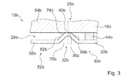
- FIG. 3 a further embodiment of the invention is shown.
- the following descriptions and the drawings are essentially limited to the differences between the exemplary embodiments, with reference in principle to the same reference components, in particular with respect to components with the same reference numerals, to the drawings and / or the description of the other embodiments, in particular Figures 1 and 2 , can be referenced.
- To distinguish the embodiments of the letter a is the reference numerals of the embodiment in the Figures 1 and 2 readjusted.
- the letter a is replaced by the letter b.
- FIG. 3 shows a fluid space device 10b of a redox device 14b.
- the fluid space device 10b comprises a first wall element 16b and a second wall element 20b.
- the wall elements 16b, 20b define a fluid space 24b and have a sealing area 28b, which closes the fluid space 24b against gas exchange with respect to an ambient space 30b.
- the redox device 14b is formed as an electrolyzer.
- the fluid space device 10b is formed as a half cell of the electrolyzer.
- the second wall element 20b in the sealing region 28b has a sealing contour 32b, which is provided to provide a sealing effect and by a distance between the wall elements 16b, 20b in the sealing area 28b is reduced relative to an ambient space 30b of the sealing area 28b.
- the first wall element 16b has a smooth, flat surface in the sealing region 28b.
- the second wall member 20b has a surface facing the first wall member 16b.
- the sealing contour 32b is formed as a bulge on the surface facing the first wall element 16b. The bulge has the shape of a wave.
- the sealing contour 32b is arranged concentrically with respect to an edge of the first wall element 16b and an edge of the second wall element 20b.
- the sealing contour 32b is formed integrally with the base body 54b and has a hood-shaped cross section arranged in the radial direction.
- the sealing contour 32b has a height of 1 mm with a shape tolerance of 0.05 mm.
- the bulge forms a groove on a side facing away from the first wall element 16b.
- the first wall element 16b and the second wall element 20b have in the sealing region 28b a sealing surface 36b, 40b, which provides a gas-tight sealing effect.
- the sealing contour 32b has an edge 62b leading to the first wall element 16b and an edge 66b leading away from the first wall element 16b.
- the flanks 62b, 66b are arranged in mirror image relative to one another in a radial direction.
- the flanks 62b, 66b each have an inclination of 45 degrees with respect to the surface of the second wall element 20b.
- the sealing contour 32b has on the surface of the second wall element 20b a base 70b with a width of 3 mm.
- the sealing contour 32b has a comb 74b in a region between ends of the flanks 62b, 66b.
- the comb 74b is spaced 24 mm from the axis of the main body 54b.
- the ridge 74b is spaced 11 mm from the edge of the second wall element 20b.
- the distance of the ridge 74b from the axis corresponds to a radius of the sealing contour 32b.
- the second wall element 20b has a substantially constant thickness in comparison to an environment of the sealing contour 32b.
- the sealing surface 40b of the second wall element 20b and the sealing surface 36b of the first wall element 16b are arranged.
- the first wall element 16b and the second wall element 20b are in direct contact with each other in the region of the sealing surfaces 36b, 40b.
- the sealing surfaces 36b, 40b are strip-shaped and have a width of 0.5 mm.
Landscapes
- Chemical & Material Sciences (AREA)
- Electrochemistry (AREA)
- Engineering & Computer Science (AREA)
- Chemical Kinetics & Catalysis (AREA)
- Organic Chemistry (AREA)
- Metallurgy (AREA)
- Materials Engineering (AREA)
- General Chemical & Material Sciences (AREA)
- Life Sciences & Earth Sciences (AREA)
- Sustainable Energy (AREA)
- Sustainable Development (AREA)
- Manufacturing & Machinery (AREA)
- Inorganic Chemistry (AREA)
- Physical Or Chemical Processes And Apparatus (AREA)
- Electrolytic Production Of Non-Metals, Compounds, Apparatuses Therefor (AREA)
- Fuel Cell (AREA)
Abstract
Description
- Die Erfindung betrifft eine Fluidraumvorrichtung nach dem Oberbegriff des Anspruchs 1.
- Es sind bereits Fluidraumvorrichtungen mit Dichtbereichen bekannt, in denen ein Dichtelement zwischen zwei parallel verlaufenden Wandelementen angeordnet ist.
- Die Aufgabe der Erfindung besteht insbesondere darin, eine gattungsgemäße Vorrichtung mit verbesserten Eigenschaften hinsichtlich einer einfachen Konstruktion bereitzustellen. Die Aufgabe wird erfindungsgemäß durch die Merkmale des Patentanspruchs 1 gelöst, während vorteilhafte Ausgestaltungen und Weiterbildungen der Erfindung den Unteransprüchen entnommen werden können.
- Die Erfindung geht aus von einer Fluidraumvorrichtung für eine Reaktionseinheit einer Redox-Vorrichtung, mit zumindest einem ersten Wandelement und zumindest einem zweiten Wandelement, die zumindest teilweise einen Fluidraum begrenzen, und mit einem Dichtbereich, der den Fluidraum gegen einen Fluidaustausch, insbesondere einen Gasaustausch, gegenüber einem Umgebungsraum abschließt.
- Es wird vorgeschlagen, dass zumindest eines der Wandelemente in einem montierten Zustand in dem Dichtbereich zumindest eine Dichtkontur aufweist, die dazu vorgesehen ist, eine Dichtwirkung bereitzustellen und durch die sich ein Abstand der zumindest zwei Wandelemente im Dichtbereich gegenüber einem Umgebungsbereich des Dichtbereichs verringert.
- Unter einer "Fluidraumvorrichtung" soll insbesondere eine Vorrichtung mit zumindest einem Fluidraum, der durch zumindest ein Wandelement begrenzt wird, verstanden werden. Unter einem "Fluidraum" soll insbesondere ein Raum zu einer Aufbewahrung und/oder Leitung eines Fluids, insbesondere eines Gases, verstanden werden, der zumindest weitgehend ein ungeregeltes Entweichen des Fluids in eine Umgebung vermeidet. Unter "zumindest weitgehend ein ungeregeltes Entweichen des Fluids in eine Umgebung vermeiden" soll insbesondere verstanden werden, dass eine Leckrate des Fluids maximal ein Prozent einer in dem Fluidraum aufgenommenen Anfangsmenge pro Stunde beträgt. Unter einer "Reaktionseinheit" soll insbesondere eine Einheit mit einem Fluidraum verstanden werden, die zu einer Durchführung einer chemischen Reaktion vorgesehen ist, beispielsweise einer elektrochemischen Reaktion. Unter einer "Redox-Vorrichtung" soll insbesondere eine Vorrichtung mit zumindest einer Redox-Einheit verstanden werden. Bevorzugt ist die Redox-Vorrichtung als Wasserstoff-Sauerstoff-Redox-Vorrichtung mit zumindest einer Wasserstoff-Sauerstoff-Redox-Einheit ausgebildet. Unter einer "Redox-Einheit" soll eine Einheit mit zumindest zwei Elektroden, wovon vorzugsweise eine als eine Wasserstoffelektrode und eine als eine Sauerstoffelektrode ausgebildet ist, mit einem die zwei Elektroden verbindenden Stromkreis, mit zumindest einem zumindest zwischen den zwei Elektroden angeordneten Elektrolyt und/oder mit einer zumindest zwischen den zwei Elektroden angeordneten elektrolytgefüllten oder ionenleitenden Membran, verstanden werden, wobei mittels der Einheit eine Redox-Reaktion durchgeführt wird, bei der unter Energieabgabe in Form von elektrischer Leistung, die über den Stromkreis abgegeben wird, das erste Gas oxidiert und das zweite Gas reduziert wird und in einer Reaktion zu einem Produktstoff, vorzugsweise Wasser, umgesetzt werden, welches in eine Umgebung oder einen Speichertank abgegeben wird, oder bei der unter Aufwendung von Energie in Form elektrischer Leistung ein Eduktstoff, vorzugsweise Wasser, zu einer Erzeugung von einem ersten Gas, vorzugsweise molekularem Wasserstoff, und einem zweiten Gas, vorzugsweise molekularem Sauerstoff, gespalten wird und das erste Gas und das zweite Gas in die Umgebung oder in Speichertanks abgeführt werden. Insbesondere ist die Redox-Einheit als eine Brennstoffzelle, bei der unter Energieabgabe durch Stromerzeugung molekularer Wasserstoff, vorzugsweise in Form von Wasserstoffgas, und molekularer Sauerstoff, vorzugsweise in Form von Sauerstoffgas, zu Wasser reagieren, und/oder als ein Elektrolyseur für Wasserstoff und Sauerstoff, bei dem unter Energieaufnahme durch einen elektrischen Strom Wasser in molekularen Sauerstoff und molekularen Wasserstoff gespalten wird, ausgebildet. Grundsätzlich kann anstelle von Wasser als Produktstoff oder Eduktstoff ein anderer chemischer Stoff, welcher Wasserstoffatome und Sauerstoffatome enthält, verwendet werden. Beispielsweise kann die Redox-Einheit anstatt als Wasserstoff-Sauerstoff-Redox-Einheit als eine Redox-Einheit für andere Stoffe, die die anderen Stoffe in einer zu der Redoxreaktion der Wasserstoff-Sauerstoff-Redox-Einheit ähnlichen Redoxreaktion umsetzt, ausgebildet sein, beispielsweise als eine Kohlenmonoxid-Sauerstoff-Redox-Einheit, die Kohlenmonoxid und Sauerstoffgas zu Kohlendioxid umsetzt oder Kohlendioxid in Kohlenmonoxid und Sauerstoffgas spaltet. Unter einer "Redoxreaktion" soll insbesondere eine Reaktion verstanden werden, bei der zumindest zwei chemische Stoffe miteinander reagieren, wobei zumindest ein chemischer Stoff Elektronen abgibt und somit oxidiert und zumindest ein chemischer Stoff Elektronen aufnimmt und somit reduziert wird. Unter "Wasserstoffgas" soll insbesondere Wasserstoff in molekularer Form, der als Gas vorliegt, verstanden werden. Unter "Sauerstoffgas" soll insbesondere Sauerstoff in molekularer Form, der als Gas vorliegt, verstanden werden. Unter "vorgesehen" soll insbesondere speziell programmiert, ausgelegt und/oder ausgestattet verstanden werden. Darunter, dass ein Objekt zu einer bestimmten Funktion vorgesehen ist, soll insbesondere verstanden werden, dass das Objekt diese bestimmte Funktion in zumindest einem Anwendungs- und/oder Betriebszustand erfüllt und/oder ausführt. Unter einem "Dichtbereich" soll insbesondere ein Bereich der Fluidraumvorrichtung verstanden werden, der den Fluidraum gegen einen Fluidaustausch mit einem Umgebungsraum abschließt. Insbesondere kann der Dichtbereich ein Dichtelement, beispielsweise einen O-Ring, eine Gummidichtung oder eine Indiumdichtung, aufweisen, welches einen Spalt zwischen zwei Wandelementen der Fluidraumvorrichtung dichtend verschließt. Unter einem "Umgebungsraum" soll insbesondere ein Raum außerhalb der Fluidraumvorrichtung, insbesondere außerhalb der Redox-Vorrichtung, verstanden werden. Insbesondere ist der Umgebungsraum verschieden und getrennt von einem Prozessbereich, in dem eine Durchführung einer chemischen Reaktion, insbesondere einer Redox-Reaktion, vorgesehen ist und/oder Produkte oder Edukte der chemischen Reaktion gelagert werden. Unter einer "Dichtkontur" soll insbesondere eine Formgebung zumindest eines der Wandelemente verstanden werden, die sich von einer Formgebung außerhalb des Dichtbereichs unterscheidet und die eine Dichtwirkung bereitstellt. Insbesondere können mehrere Dichtkonturen aufeinander folgend, insbesondere in einer radialen Richtung der Fluidraumvorrichtung aufeinander folgend, angeordnet sein. Unter einem "Umgebungsbereich des Dichtbereichs" soll insbesondere ein Bereich in einer Nachbarschaft des Dichtbereichs verstanden werden, wobei der Umgebungsbereich sich in dem Prozessbereich und/oder in den Umgebungsbereich erstrecken kann. Insbesondere kann der Dichtbereich zusätzlich zu der Dichtkontur ein weiteres Dichtelement, beispielsweise einen Dichtring und/oder eine Beschichtung auf dem ersten Wandelement und/oder dem zweiten Wandelement aufweisen, das insbesondere in die Dichtkontur eingesetzt sein kann. Insbesondere ist eine Dichtwirkung der Dichtkontur weitgehend unabhängig von einer Schwerewirkung und/oder von einem Außendruck, wodurch die Fluidraumvorrichtung insbesondere für einen Einsatz unter Bedingungen reduzierter Schwerkraft vorteilhaft einsetzbar ist. Unter "Bedingungen reduzierter Schwerkraft" sollen insbesondere Bedingungen verstanden werden, bei denen eine Schwerewirkung von maximal 0,9 g, vorteilhaft maximal 1*10-3 g, vorzugsweise maximal 1*10-6 g und besonders bevorzugt maximal 1*10-8 g wirksam ist. Die Schwerewirkung kann durch Gravitation und/oder künstlich durch eine Beschleunigung erzeugt sein. Mit "g" ist der Wert der Fallbeschleunigung auf der Erde von 9,81 m/s2 bezeichnet. Es kann insbesondere eine Verringerung einer Anzahl an benötigten Dichtelementen des Dichtbereichs erreicht und ein besonders einfacher Aufbau der Fluidraumvorrichtung erreicht werden.
- Weiterhin wird vorgeschlagen, dass die zumindest zwei Wandelemente im Dichtbereich einen Abstand von höchstens 0,5 mm aufweisen. Es kann insbesondere ein zu dichtender Querschnitt verringert und eine hohe Dichtwirkung erreicht werden.
- Des Weiteren wird vorgeschlagen, dass das zumindest eine erste Wandelement und das zumindest eine zweite Wandelement im Dichtbereich jeweils eine Dichtfläche aufweisen, die in einem montierten Zustand eine gasdichte Dichtwirkung bereitstellt. Unter einer "Dichtfläche" soll insbesondere eine Fläche verstanden werden, die eine Dichtwirkung bereitstellt. Unter einem "montierten Zustand" soll insbesondere ein Zustand verstanden werden, in dem zumindest das zumindest eine erste Wandelement und das zumindest eine zweite Wandelement aneinander montiert sind. Es kann insbesondere eine hohe Dichtwirkung erreicht werden.
- Ferner wird vorgeschlagen, dass die zumindest zwei Wandelemente im Bereich der Dichtflächen in direktem Kontakt miteinander sind. Insbesondere wird durch den direkten Kontakt miteinander die gasdichte Dichtwirkung erreicht. Es kann insbesondere auf zusätzliche Dichtelemente zu einem Abschluss des Fluidraums gegenüber einem Fluidaustausch mit der Umgebung verzichtet werden.
- Des Weiteren wird vorgeschlagen, dass die Dichtflächen jeweils im Wesentlichen streifenförmig ausgebildet sind. Unter einer "streifenförmig ausgebildeten Dichtfläche" soll insbesondere eine Dichtfläche verstanden werden, die eine Erstreckung in eine Richtung senkrecht zu einer Haupterstreckungsrichtung aufweist, die maximal zehn Prozent, vorteilhaft maximal fünf Prozent und bevorzugt maximal ein Prozent einer Erstreckung in der Haupterstreckungsrichtung beträgt. Insbesondere ist die Haupterstreckungsrichtung der Dichtfläche von einer Radialrichtung der Fluidraumvorrichtung gebildet. Es kann insbesondere eine hohe Dichtwirkung erreicht werden.
- Weiterhin wird vorgeschlagen, dass die Dichtflächen eine Breite von weniger als 1 mm, vorteilhaft weniger als 0,5 mm, aufweisen. Unter einer "Breite der Dichtflächen" soll insbesondere eine Erstreckung der Dichtflächen in eine Richtung senkrecht zu der Haupterstreckungsrichtung der Dichtfläche verstanden werden. Es kann insbesondere eine hohe Dichtwirkung erreicht werden.
- Ferner wird vorgeschlagen, dass die Fluidraumvorrichtung zumindest ein Verspannteilelement, das eine auf die Dichtflächen wirkende Presskraft für eine druckfeste Dichtwirkung bereitstellt, aufweist. Unter einer "druckfesten Dichtwirkung" soll insbesondere eine Dichtwirkung verstanden werden, bei der bei einer Druckdifferenz zwischen dem Fluidraum und dem Umgebungsraum von 60 bar, vorteilhaft 80 bar und bevorzugt 100 bar ein Druckverlust und/oder Druckanstieg von maximal 0,01 bar pro Stunde auftritt. Beispielsweise kann das Verspannteilelement als ein die Fluidraumvorrichtung umgebender, durch Verschraubung einen Druck auf die Fluidraumvorrichtung ausübender Rahmen ausgebildet sein. Vorzugsweise weist ein Material des ersten Wandelements und des zweiten Wandelements eine ausreichende Elastizität auf, so dass durch die Presskraft eine reversible elastische Verformung erreicht wird. Es kann insbesondere eine hohe Dichtwirkung erreicht werden.
- Des Weiteren wird vorgeschlagen, dass die Fluidraumvorrichtung zumindest ein zwischen dem zumindest ersten Wandelement und dem zumindest zweiten Wandelement angeordnetes Distanzelement aufweist, das dazu vorgesehen ist, die auf die Kontaktflächen wirkende Presskraft zu begrenzen. Unter einem "Distanzelement" soll insbesondere ein Element mit einer Materialelastizität verstanden werden, die wesentlich niedriger, insbesondere zumindest um fünf Prozent niedriger, vorteilhaft zumindest um zehn Prozent und bevorzugt zumindest um zwanzig Prozent niedriger ist als eine niedrigste Materialelastizität des ersten Wandelements und/oder des zweiten Wandelements. Insbesondere ist das Distanzelement dazu vorgesehen, die Presskraft zu begrenzen, um eine plastische Verformung des ersten Wandelements und/oder des zweiten Wandelements durch die Presskraft zu vermeiden. Insbesondere kann der Dichtbereich somit im Bedarfsfall reversibel geöffnet werden.
- Weiterhin wird vorgeschlagen, dass die zumindest eine Dichtkontur als eine Aufwölbung des zumindest einen Wandelements ausgebildet ist, die einen Kamm aufweist, auf dem die Dichtfläche des zumindest einen anderen Wandelements angeordnet ist. Unter einer "Aufwölbung" soll insbesondere eine Erhebung des Wandelements im Bereich eines Streifens verstanden werden, vorzugsweise durch eine zumindest einseitige Vergrößerung der Dicke des Wandelements und/oder durch eine wellenförmige Formgebung entlang einer Breite des Streifens. Insbesondere kann die Aufwölbung als eine massive Kontur ausgebildet sein, bei der eine Dicke des Wandelements sich verändert und/oder als eine Kontur mit einer konstanten Dicke, bei der sich ein Verlauf des Wandelements verändert. Es kann insbesondere eine konstruktionstechnisch einfach herstellbare Dichtkontur erreicht werden.
- Ferner wird vorgeschlagen, dass die Wandelemente aus zumindest im Wesentlichen verschiedenen Materialien ausgebildet sind. Unter "zumindest im Wesentlichen verschiedenen Materialien" soll insbesondere verstanden werden, dass sich Materialien des ersten Wandelements und des zweiten Wandelements zumindest hinsichtlich zumindest eines Materialkennwerts, wie beispielsweise einer Härte, eines spezifischen Gewichts oder einer elektrischen Leitfähigkeit unterscheiden und vorteilhaft zumindest teilweise aus unterschiedlichen Atomsorten oder Molekülsorten bestehen. Bevorzugt gehören Materialien des ersten Wandelements und des zweiten Wandelements unterschiedlichen Materialklassen an, beispielsweise kann das erste Wandelement aus einem Kunststoff bestehen und das zweite Wandelement aus einem metallischen Werkstoff. Insbesondere kann das erste Wandelement zumindest teilweise aus einem Polyetheretherketon und/oder einem Polysulfon bestehen, wobei in eine Matrix aus Polyetheretherketon und/oder einem Polysulfon weitere Stoffe eingebracht sein können. Insbesondere kann das zweite Wandelement zumindest teilweise aus einem elektrisch leitenden Material mit einer hohen Streckgrenze bestehen, vorzugsweise aus einem metallischen Material, wie beispielsweise aus einem nickelhaltigen Blech. Es kann insbesondere eine gezielte Abstimmung von Eigenschaften der Wandelemente auf Anforderungen der jeweiligen Reaktionseinheit erreicht werden.
- Des Weiteren wird vorgeschlagen, dass eine Haupterstreckung der Wandelemente mindestens das 30-fache einer Höhe des Fluidraums beträgt. Unter einer "Höhe des Fluidraums" soll insbesondere ein mittlerer Abstand des zumindest einen ersten Wandelements und des zumindest einen zweiten Wandelements verstanden werden, den das zumindest eine erste Wandelement und das zumindest eine zweite Wandelement in einem Bereich eines geometrischen Zentrums des Fluidraums und im einem um das geometrische Zentrum des Fluidraums zentrierten Bereich, welcher zumindest neunzig Prozent eines Volumens des Fluidraums einschließt, aufweist. Bevorzugt ist der Fluidraum so ausgebildet, dass er bis auf Randbereiche eine konstante Höhe aufweist. Es kann insbesondere eine kompakte Fluidraumvorrichtung erreicht werden.
- Ferner wird vorgeschlagen, dass zumindest eines der Wandelemente einen fluiddurchlässigen Teilbereich aufweist. Unter einem "fluiddurchlässigen Teilbereich" soll insbesondere ein Bereich verstanden werden, durch den ein Fluid durchtreten kann, beispielsweise durch Diffusion durch ein Gitter von Atomen und/oder Molekülen eines Materials des fluiddurchlässigen Teilbereichs oder durch speziell dazu vorgesehen Öffnungen und/oder Poren des fluiddurchlässigen Bereichs. Bevorzugt ist der fluiddurchlässige Teilbereich einstückig mit einer Elektrode der Redox-Vorrichtung ausgebildet. Insbesondere wird somit eine fluiddurchlässige Verbindung von dem Fluidraum zu einem Funktionselement der Redox-Vorrichtung, wie beispielsweise einer Membran, und/oder einem weiteren Fluidraum erreicht. Es kann insbesondere ein Verzicht auf zusätzliche, fluiddurchlässige Wandelemente erreicht werden.
- Weiterhin wird eine Redox-Vorrichtung mit zumindest einer ersten erfindungsgemäßen Fluidraumvorrichtung und zumindest einer zweiten erfindungsgemäßen Fluidraumvorrichtung vorgeschlagen. Insbesondere bilden die zumindest eine erste erfindungsgemäße Fluidraumvorrichtung und die zumindest eine zweite erfindungsgemäße Fluidraumvorrichtung jeweils eine Halbzelle eines Reaktionsbereichs der Redox-Vorrichtung.
- Des Weiteren wird vorgeschlagen, dass die Fluidraumvorrichtungen in einer Richtung senkrecht zu einer Haupterstreckung direkt benachbart angeordnet sind. Insbesondere können mehrere Redox-Vorrichtungen direkt benachbart angeordnet sein, wobei insbesondere Fluidraumvorrichtungen direkt benachbarter Redox-Vorrichtungen beispielsweise in Form eines sogenannten Stacks angeordnet sind. Es kann insbesondere eine platzsparende Anordnung mehrerer Fluidraumvorrichtung erreicht werden.
- Ferner wird vorgeschlagen, dass die Fluidraumvorrichtungen in einer Richtung senkrecht zu einer Haupterstreckung spiegelbildlich zueinander angeordnet sind. Insbesondere grenzen zumindest ein erstes Wandelement oder zumindest ein zweites Wandelement der zumindest einen ersten Fluidraumvorrichtung und zumindest ein erstes Wandelement oder zumindest ein zweites Wandelement der zumindest einen zweiten Fluidraumvorrichtung aneinander und sind im Wesentlichen gleich ausgebildet. Unter "im Wesentlichen gleich ausgebildet" soll insbesondere aus dem gleichen Material bestehend verstanden werden. Es kann insbesondere eine konstruktionstechnisch einfach herzustellende direkt benachbarte Anordnung erreicht werden.
- Die erfindungsgemäße Fluidraumvorrichtung soll hierbei nicht auf die oben beschriebene Anwendung und Ausführungsform beschränkt sein. Insbesondere kann die erfindungsgemäße Fluidraumvorrichtung zu einer Erfüllung einer hierin beschriebenen Funktionsweise eine von einer hierin genannten Anzahl von einzelnen Elementen, Bauteilen und Einheiten abweichende Anzahl aufweisen.
- Weitere Vorteile ergeben sich aus der folgenden Zeichnungsbeschreibung. In den Zeichnungen sind zwei Ausführungsbeispiele der Erfindung dargestellt. Die Zeichnungen, die Beschreibung und die Ansprüche enthalten zahlreiche Merkmale in Kombination. Der Fachmann wird die Merkmale zweckmäßigerweise auch einzeln betrachten und zu sinnvollen weiteren Kombinationen zusammenfassen.
- Es zeigen:
- Fig. 1
- einen Schnitt in radialer Richtung durch einen Randbereich einer Redox-Vorrichtung mit zwei erfindungsgemäßen Fluidraumvorrichtungen,
- Fig. 2
- einen Schnitt in radialer Richtung durch eine der Fluidraumvorrichtungen der Redox-Vorrichtung und
- Fig. 3
- einen Schnitt in radialer Richtung durch eine Fluidraumvorrichtung einer Redox-Vorrichtung eines weiteren Ausführungsbeispiels.
-
Figur 1 zeigt einen Ausschnitt einer Redox-Vorrichtung 14 mit einer ersten und einer zweiten Fluidraumvorrichtung 10a, 12a. Dargestellt ist ein Schnitt in radialer Richtung in einem Randbereich der Redox-Vorrichtung. Die Fluidraumvorrichtungen 10a, 12a sind analog zueinander ausgebildet, weswegen im Folgenden nur die erste Fluidraumvorrichtung 10a näher beschrieben wird. Dabei verweisen die Bezugszeichen jeweils auf die entsprechenden Elemente sowohl der ersten Fluidraumvorrichtung 10a als auch der zweiten Fluidraumvorrichtung 12a. Die Fluidraumvorrichtung 10a, 12a umfasst ein erstes Wandelement 16a, 18a und ein zweites Wandelement 20a, 22a. Die Wandelemente 16a, 18a, 20a, 22a begrenzen einen Fluidraum 24a, 26a und weisen einen Dichtbereich 28a auf, der den Fluidraum 24a, 26a gegen einen Gasaustausch gegenüber einem Umgebungsraum 30a abschließt. Die Redox-Vorrichtung 14 ist als ein Elektrolyseur für eine Spaltung von Wasser in Wasserstoff und Sauerstoff ausgebildet. Die Fluidraumvorrichtung 10a, 12a ist als eine Halbzelle des Elektrolyseurs ausgebildet (vgl.Figur 2 ). Die Redox-Vorrichtung 14a weist einen Prozessbereich 52a auf, der den Fluidraum 24a, 26a der Fluidraumvorrichtung 10a, 12a umfasst. - Das erste Wandelement 16a, 18a und das zweite Wandelement 20a, 22a bestehen aus im Wesentlichen unterschiedlichen Materialien. Das erste Wandelement 16a, 18a besteht aus einem elektrisch isolierenden Material. Das erste Wandelement 16a, 18a besteht aus einem Thermoplast. Das erste Wandelement 16a, 18a besteht aus einem Polysulfon. Das erste Wandelement 16a, 18a umfasst einen scheibenförmigen Grundkörper 54a, 56a. Der Grundkörper 54a, 56a weist einen Durchmesser von 70 mm und eine Dicke von 18 mm auf. Der Durchmesser des Grundkörpers 54a, 56a entspricht einer Haupterstreckung des ersten Wandelements 16a, 18a. Das zweite Wandelement 20a, 22a besteht aus einem metallischen, elektrisch leitenden Material, das eine hohe Streckgrenze aufweist. Das zweite Wandelement 20a, 22a besteht aus einem nickelhaltigen Blech. Das zweite Wandelement 20a, 22a umfasst einen scheibenförmigen Grundkörper 58a, 60a. Der Grundkörper 54a, 56a weist einen Durchmesser von 70 mm und eine Dicke von 5 mm auf. Der Durchmesser entspricht einer Haupterstreckung des zweiten Wandelements 20a, 22a. Der Durchmesser des Grundkörpers 58a, 60a des zweiten Wandelements 20a, 22a entspricht dem Durchmesser des Grundkörpers 54a, 56a des ersten Wandelements 16a, 18a. Das erste Wandelement 16a, 18a und das zweite Wandelement 20a, 22a weisen eine gemeinsame Achse auf. Das erste Wandelement 16a, 18a und das zweite Wandelement 20a, 22a sind parallel zueinander und koaxial angeordnet. In axialer Richtung ist zwischen den Wandelementen 16a, 18a, 20a, 22a der Fluidraum 24a, 26a angeordnet, der dazu vorgesehen ist, ein Prozessgas aufzunehmen. Der Fluidraum 24a, 26a weist eine Höhe von 1 mm auf. In den Fluidräumen 24a, 26a ist jeweils ein Prozessgas aufgenommen, wobei in den Fluidräumen 24a, 26a ein Druck von 100 bar herrscht.
- Das erste Wandelement 16a, 18a weist in dem Dichtbereich 28a eine Dichtkontur 32a, 34a auf, die dazu vorgesehen ist, eine Dichtwirkung bereitzustellen und durch die sich ein Abstand zwischen den Wandelementen 16a, 18a, 20a, 22a im Dichtbereich 28a gegenüber einem Umgebungsraum 30a des Dichtbereichs 28a verringert. Das erste Wandelement 16a, 18a weist eine Oberfläche auf, die dem zweiten Wandelement 20a, 22a zugewandt ist. Die Dichtkontur 32a, 34a ist als eine Aufwölbung auf der dem zweiten Wandelement 20a, 22a zugewandten Oberfläche ausgebildet. Das zweite Wandelement 20a, 22a weist in dem Dichtbereich 28 eine ebene, glatte Oberfläche auf. Die Aufwölbung weist die Form einer ringförmigen massiven Schwelle auf. Die Dichtkontur 32a, 34a ist konzentrisch zu einem Rand des ersten Wandelements 16a, 18a, und einem Rand des zweiten Wandelements 20a, 22a angeordnet. Die Dichtkontur 32a, 34a ist einstückig mit dem Grundkörper 54a, 56a ausgebildet und weist einen in radialer Richtung angeordneten trapezförmigen Querschnitt auf. Die Dichtkontur 32a, 34a weist eine Höhe von 1 mm mit einer Formtoleranz von 0,05 mm auf. Das erste Wandelement 16a, 18a und das zweite Wandelement 20a, 22a weisen im Dichtbereich 28a jeweils eine Dichtfläche 36a, 38a, 40a, 42a auf, die eine gasdichte Dichtwirkung bereitstellt.
- Die Dichtkontur 32a, 34a weist eine auf das zweite Wandelement 20a, 22a zuführende Flanke 62a, 64a und eine von dem zweiten Wandelement 20a, 22a wegführende Flanke 66a, 68a auf. Die Flanken 62a, 64a, 66a, 68a sind in einer radialen Richtung spiegelbildlich zueinander angeordnet. Die Flanken 62a, 64a, 66a, 68a weisen jeweils eine Neigung von 30 Grad gegenüber der Oberfläche des ersten Wandelements 16a, 18a auf. Die Dichtkontur 32a, 34a weist an der Oberfläche des ersten Wandelements 16a, 18a eine Basis 70a, 72a mit einer Breite von 4,5 mm auf. Die Dichtkontur 32a, 34a weist in einem Bereich zwischen Enden der Flanken 62a, 64a, 66a, 68a einen Kamm 74a, 76a auf. Der Kamm 74a, 76a weist einen Abstand von 24 mm von der Achse des Grundkörpers 54a, 56a, 58a, 60a auf. Der zweifache Abstand des Kamms 74a, 76a von der Achse des Grundkörpers 54a, 56a entspricht einer Haupterstreckung des Fluidraums 24a, 26a. Eine Haupterstreckung des Fluidraums 24a, 26a beträgt das 48-fache der Höhe des Fluidraums 24a, 26a. Der Kamm 74a, 76a weist einen Abstand von 11 mm von dem Rand des ersten Wandelements 16a, 18a auf. Der Abstand des Kamms 74a, 76a von der Achse entspricht einem Radius der Dichtkontur 32a, 34a. Das erste Wandelement 16a, 18a weist im Bereich der Dichtkontur 32a, 34a eine vergrößerte Dicke und im Bereich des Kamms 74a, 76a eine maximale Dicke auf. Auf dem Kamm 74a, 76a ist die Dichtfläche 40a, 42a des zweiten Wandelements 20a, 22a angeordnet ist. Das erste Wandelement 16a, 18a und das zweite Wandelement 20a, 22a sind im Bereich der Dichtflächen 36a, 38a, 40a, 42a in direktem Kontakt miteinander. Die Dichtflächen 36a, 38a, 40a, 42a sind streifenförmig ausgebildet und weisen eine Breite von 0,5 mm auf.
- Die Fluidraumvorrichtung 10a, 12a weist ein Verspannteilelement auf, das eine auf die Dichtflächen 36a, 38a, 40a, 42a wirkende Presskraft für eine druckfeste Dichtwirkung bereitstellt. Die Presskraft verformt die Dichtkontur 32a, 34a elastisch und reduziert die Höhe der Dichtkontur 32a, 34a um etwa 0,1 mm, wodurch eine Dichtwirkung im Bereich der Dichtflächen 36a, 38a erzielt wird. Die Dichtkontur 32a, 34a stellt eine Rückstellkraft bereit, die der Presskraft auf die Dichtflächen 36a, 38a entspricht. Die Fluidraumvorrichtung 10a, 12a umfasst ein zwischen dem ersten Wandelement 16a, 18a und dem zweiten Wandelement 20a, 22a angeordnetes Distanzelement 44a, 46a, das dazu vorgesehen ist, eine Presskraft auf die Dichtflächen 36a, 38a, 40a, 42a und die Dichtkontur 32a, 34a zu begrenzen, wodurch eine Verformung der Dichtkontur 32a, 34a in einem elastischen Bereich liegt und eine dauerhafte plastische Verformung der Dichtkontur 32a, 34a vermieden wird. Das Distanzelement 44a, 46a ist in Form eines Rings ausgebildet und weist einen rechteckigen Querschnitt auf. Das Distanzelement 44a, 46a ist in radialer Richtung außerhalb der Dichtkontur 32a, 34a angeordnet. Das Distanzelement 44a, 46a ist außerhalb des Fluidraums 24a, 26a im Umgebungsraum 30a angeordnet. Grundsätzlich ist es denkbar, dass das Distanzelement 44a, 46a einen Querschnitt in einer anderen geeigneten Form und die Fluidraumvorrichtung 10a, 12a eine Mehrzahl von Distanzelementen 44a, 46a aufweist.
- Das erste Wandelement 16a, 18a weist nicht dargestellte Kanäle zu einem Transport von Prozessstoffen auf. Die Kanäle umfassen radial ausgerichtete Röhren und axial verlaufende Bohrungen, die den Fluidraum 24a, 26a mit einer nicht dargestellten Ableitung verbinden. Das zweite Wandelement 20a, 22a ist dazu vorgesehen, den Prozessbereich 52a mit einer nicht dargestellten elektrischen Spannungsquelle zu verbinden und einen elektrischen Strom in den Prozessbereich 52a zu leiten. Das zweite Wandelement 20a, 22a ist ferner dazu vorgesehen, eine Prozesswärme aus dem Prozessbereich 52a abzuleiten. Das zweite Wandelement 20a, 22a weist nicht näher dargestellte Kanäle auf, die zu einem Kühlmitteltransport vorgesehen sind.
- Die erste Fluidraumvorrichtung 10a und die zweite Fluidraumvorrichtung 12a bilden zusammen eine Zelle des Elektrolyseurs aus (vgl.
Figur 1 ). Die Zelle umfasst eine Membran 78a, die in axialer Richtung zwischen der ersten Fluidraumvorrichtung 10a und der zweiten Fluidraumvorrichtung 12a angeordnet ist. Die erste Fluidraumvorrichtung 10a und die zweite Fluidraumvorrichtung 12a sind in axialer Richtung spiegelbildlich zueinander angeordnet. In axialer Richtung sind das erste Wandelement 16a, der Fluidraum 24a und das zweite Wandelement 20a der ersten Fluidraumvorrichtung 10a, die Membran 78a, das zweite Wandelement 22a der zweiten Fluidraumvorrichtung 12a, der Fluidraum 26a und das erste Wandelement 18a der zweiten Fluidraumvorrichtung 12a benachbart zueinander angeordnet. Die Dichtkontur 32a der ersten Fluidraumvorrichtung 10a und die Dichtkontur 34a der zweiten Fluidraumvorrichtung 12a sind in einem montierten Zustand einander zugewandt. Das zweite Wandelement 20a der ersten Fluidraumvorrichtung 10a und das zweite Wandelement 22a der zweiten Fluidraumvorrichtung 12a sind in einem Betriebszustand der Zelle mit unterschiedlichen Polen einer nicht näher dargestellten elektrischen Spannungsquelle verbunden. Das zweite Wandelement 20a der ersten Fluidraumvorrichtung 10a ist mit einem negativen Pol und das zweite Wandelement 22a der zweiten Fluidraumvorrichtung 12a ist mit einem positiven Pol der Spannungsquelle verbunden. - In der Zelle des Elektrolyseurs sind die Membran 78a, welche mit einem Elektrolyten gefüllt ist, sowie zwei Elektroden 80a, 82a angeordnet. Als Elektrolyt wird eine Kaliumhydroxidlösung verwendet. Die Membran 78a ist zwischen dem zweiten Wandelement 20a der ersten Fluidraumvorrichtung 10a und dem zweiten Wandelement 22a der zweiten Fluidraumvorrichtung 12a angeordnet. Die Elektroden 80a, 82a sind jeweils als ein poröser Teilbereich 48a, 50a des zweiten Wandelements 20a der ersten Fluidraumvorrichtung 10a und des zweiten Wandelements 22a der zweiten Fluidraumvorrichtung 12a ausgebildet, die an die Membran 78a angrenzen. In einem Betrieb wird der Membran 78a Wasser zu einer elektrolytischen Spaltung gemäß einer bekannten Elektrolysereaktion zugeführt. In Elektrolysebereichen 84a, 86a, die von Kontaktbereichen der Membran 78a und jeweils einer Elektrode 80a, 82a gebildet sind, entstehen Wasserstoff und Sauerstoff in Gasform als Produkte der elektrolytischen Spaltung. Wasserstoff und Sauerstoff entstehen in unterschiedlichen Elektrolysebereichen 84a, 86a, die unterschiedlichen Fluidräumen 24a, 26a zugeordnet sind, und diffundieren durch die Elektrode 80a, 82a in den jeweiligen Fluidraum 24a, 26a. Aus den Fluidräumen 24a, 26a werden sie mittels nicht dargestellter Ableitungen in Gasspeicher geleitet.
- In der
Figur 3 ist ein weiteres Ausführungsbeispiel der Erfindung gezeigt. Die nachfolgenden Beschreibungen und die Zeichnungen beschränken sich im Wesentlichen auf die Unterschiede zwischen den Ausführungsbeispielen, wobei bezüglich gleich bezeichneter Bauteile, insbesondere in Bezug auf Bauteile mit gleichen Bezugszeichen, grundsätzlich auch auf die Zeichnungen und/oder die Beschreibung der anderen Ausführungsbeispiele, insbesondere derFiguren 1 und 2 , verwiesen werden kann. Zur Unterscheidung der Ausführungsbeispiele ist der Buchstabe a den Bezugszeichen des Ausführungsbeispiels in denFiguren 1 und 2 nachgestellt. In dem Ausführungsbeispiel derFigur 3 ist der Buchstabe a durch den Buchstaben b ersetzt. -
Figur 3 zeigt eine Fluidraumvorrichtung 10b einer Redox-Vorrichtung 14b. Die Fluidraumvorrichtung 10b umfasst ein erstes Wandelement 16b und ein zweites Wandelement 20b. Die Wandelemente 16b, 20b begrenzen einen Fluidraum 24b und weisen einen Dichtbereich 28b auf, der den Fluidraum 24b gegen einen Gasaustausch gegenüber einem Umgebungsraum 30b abschließt. Die Redox-Vorrichtung 14b ist als ein Elektrolyseur ausgebildet. Die Fluidraumvorrichtung 10b ist als eine Halbzelle des Elektrolyseurs ausgebildet. - Im Unterschied zu dem vorherigen Ausführungsbeispiel weist anstelle des ersten Wandelements 16b, das zweite Wandelement 20b in dem Dichtbereich 28b eine Dichtkontur 32b auf, die dazu vorgesehen ist, eine Dichtwirkung bereitzustellen und durch die sich ein Abstand zwischen den Wandelementen 16b, 20b im Dichtbereich 28b gegenüber einem Umgebungsraum 30b des Dichtbereichs 28b verringert. Das erste Wandelement 16b weist in dem Dichtbereich 28b eine glatte, ebene Oberfläche auf. Das zweite Wandelement 20b weist eine Oberfläche auf, die dem ersten Wandelement 16b zugewandt ist. Die Dichtkontur 32b ist als eine Aufwölbung an der dem ersten Wandelement 16b zugewandten Oberfläche ausgebildet. Die Aufwölbung weist die Form einer Welle auf. Die Dichtkontur 32b ist konzentrisch zu einem Rand des ersten Wandelements 16b und einem Rand des zweiten Wandelements 20b angeordnet. Die Dichtkontur 32b ist einstückig mit dem Grundkörper 54b ausgebildet und weist einen in radialer Richtung angeordneten haubenförmigen Querschnitt auf. Die Dichtkontur 32b weist eine Höhe von 1 mm mit einer Formtoleranz von 0,05 mm auf. Die Aufwölbung bildet auf einer dem ersten Wandelement 16b abgewandten Seite eine Rille aus.
- Das erste Wandelement 16b und das zweite Wandelement 20b weisen im Dichtbereich 28b eine Dichtfläche 36b, 40b auf, die eine gasdichte Dichtwirkung bereitstellt. Die Dichtkontur 32b weist eine auf das erste Wandelement 16b zuführende Flanke 62b und eine vom ersten Wandelement 16b wegführende Flanke 66b auf. Die Flanken 62b, 66b sind in einer radialen Richtung spiegelbildlich zueinander angeordnet. Die Flanken 62b, 66b weisen jeweils eine Neigung von 45 Grad gegenüber der Oberfläche des zweiten Wandelements 20b auf. Die Dichtkontur 32b weist an der Oberfläche des zweiten Wandelement 20b eine Basis 70b mit einer Breite von 3 mm auf. Die Dichtkontur 32b weist in einem Bereich zwischen Enden der Flanken 62b, 66b einen Kamm 74b auf. Der Kamm 74b weist einen Abstand von 24 mm von der Achse des Grundkörpers 54b auf. Der Kamm 74b weist einen Abstand von 11 mm von dem Rand des zweiten Wandelements 20b auf. Der Abstand des Kamms 74b von der Achse entspricht einem Radius der Dichtkontur 32b. Das zweite Wandelement 20b weist im Bereich der Dichtkontur 32b eine im Wesentlichen gleichbleibende Dicke im Vergleich zu einer Umgebung der Dichtkontur 32b. Auf dem Kamm 74b sind die Dichtfläche 40b des zweiten Wandelements 20b und die Dichtfläche 36b des ersten Wandelements 16b angeordnet. Das erste Wandelement 16b und das zweite Wandelement 20b sind im Bereich der Dichtflächen 36b, 40b in direktem Kontakt miteinander. Die Dichtflächen 36b, 40b sind streifenförmig ausgebildet und weisen eine Breite von 0,5 mm auf.
Claims (15)
- Fluidraumvorrichtung für eine Reaktionseinheit einer Redox-Vorrichtung, mit zumindest einem ersten Wandelement (16a, 18a; 16b) und zumindest einem zweiten Wandelement (20a, 22a; 22b), die zumindest teilweise einen Fluidraum (24a, 26a; 24b) begrenzen, und mit einem Dichtbereich (28a; 28b), der den Fluidraum (24a, 26a; 24b) gegen einen Fluidaustausch, insbesondere einen Gasaustausch, gegenüber einem Umgebungsraum (30a; 30b) abschließt,
dadurch gekennzeichnet, dass
zumindest eines der Wandelemente (16a, 18a, 20a, 22a; 16b, 20b) in einem montierten Zustand in dem Dichtbereich (28a; 28b) zumindest eine Dichtkontur (32a, 34a; 32b) aufweist, die dazu vorgesehen ist, eine Dichtwirkung bereitzustellen und durch die sich ein Abstand der zumindest zwei Wandelemente (16a, 18a, 20a, 22a; 16b, 20b) im Dichtbereich (28a; 28b) gegenüber einem Umgebungsbereich des Dichtbereichs (28a; 28b) verringert. - Fluidraumvorrichtung nach Anspruch 1,
dadurch gekennzeichnet, dass
die zumindest zwei Wandelemente (16a, 18a, 20a, 22a; 16b, 20b) im Dichtbereich (28a; 28b) einen Abstand von höchstens 0,5 mm aufweisen. - Fluidraumvorrichtung nach Anspruch 1 oder 2,
dadurch gekennzeichnet, dass
das zumindest erste Wandelement (16a, 18a; 16b) und das zumindest zweite Wandelement (20a, 22a; 20b) in dem Dichtbereich (28a; 28b) jeweils eine Dichtfläche (36a, 38a, 40a, 42a; 36b, 40b) aufweisen, die in einem montierten Zustand eine gasdichte Dichtwirkung bereitstellt. - Fluidraumvorrichtung nach Anspruch 3,
dadurch gekennzeichnet, dass
die zumindest zwei Wandelemente (16a, 18a, 20a, 22a; 16b, 20b) im Bereich der Dichtfläche (36a, 38a, 40a, 42a; 36b, 40b) in direktem Kontakt miteinander sind. - Fluidraumvorrichtung zumindest nach Anspruch 3,
dadurch gekennzeichnet, dass
die Dichtflächen (36a, 38a, 40a, 42a; 36b, 40b) jeweils im Wesentlichen streifenförmig ausgebildet sind. - Fluidraumvorrichtung nach Anspruch 5,
dadurch gekennzeichnet, dass
die Dichtflächen (36a, 38a, 40a, 42a; 36b, 40b) eine Breite von maximal 1 mm aufweisen. - Fluidraumvorrichtung zumindest nach Anspruch 3,
gekennzeichnet durch
zumindest ein Verspannteilelement, das eine auf die Dichtflächen (36a, 38a, 40a, 42a; 36b, 40b) wirkende Presskraft für eine druckfeste Dichtwirkung bereitstellt. - Fluidraumvorrichtung nach Anspruch 7,
gekennzeichnet durch
zumindest ein zwischen dem zumindest ersten Wandelement (16a, 18a; 16b) und dem zumindest zweiten Wandelement (20a, 22a; 20b) angeordnetes Distanzelement (44a, 46a; 44b), das dazu vorgesehen ist, die auf die Dichtflächen (36a, 38a, 40a, 42a; 36b, 40b) wirkende Presskraft zu begrenzen. - Fluidraumvorrichtung zumindest nach Anspruch 3,
dadurch gekennzeichnet, dass
die zumindest eine Dichtkontur (32a, 34a; 32b) als eine Aufwölbung des zumindest einen Wandelements (16a, 18a; 20b) ausgebildet ist, die einen Kamm (74a, 76a; 74b) aufweist, auf dem die Dichtfläche (40a, 42a; 36b) des zumindest einen anderen Wandelements (20a, 22a; 16b) angeordnet ist. - Fluidraumvorrichtung nach einem der vorhergehenden Ansprüche,
dadurch gekennzeichnet, dass
die Wandelemente (16a, 18a, 20a, 22a; 16b, 20b) aus zumindest im Wesentlichen verschiedenen Materialien ausgebildet sind. - Fluidraumvorrichtung nach einem der vorhergehenden Ansprüche,
dadurch gekennzeichnet, dass
eine Haupterstreckung der Wandelemente (16a, 18a, 20a, 22a; 16b, 20b) mindestens das 30-fache einer Höhe des Fluidraums (24a, 26a; 24b) beträgt. - Fluidraumvorrichtung nach einem der vorhergehenden Ansprüche,
dadurch gekennzeichnet, dass
zumindest eines der Wandelemente (16a, 18a, 20a, 22a; 16b, 20b) einen fluiddurchlässigen Teilbereich (48a, 50a) aufweist. - Redox-Vorrichtung mit zumindest einer ersten Fluidraumvorrichtung (10a; 10b) und zumindest einer zweiten Fluidraumvorrichtung (12a), jeweils nach einem der vorhergehenden Ansprüche.
- Redox-Vorrichtung nach Anspruch 13,
dadurch gekennzeichnet, dass
die Fluidraumvorrichtungen (10a, 12a; 12b) in einer Richtung senkrecht zu einer Haupterstreckung direkt benachbart angeordnet sind. - Redox-Vorrichtung nach Anspruch 13,
dadurch gekennzeichnet, dass
die Fluidraumvorrichtungen (10a, 12a; 12b) in einer Richtung senkrecht zu einer Haupterstreckung spiegelbildlich zueinander angeordnet sind.
Priority Applications (3)
| Application Number | Priority Date | Filing Date | Title |
|---|---|---|---|
| EP13173675.3A EP2818582B1 (de) | 2013-06-25 | 2013-06-25 | Fluidraumvorrichtung für eine Reaktionseinheit einer Redox-Vorrichtung |
| CA2854151A CA2854151C (en) | 2013-06-25 | 2014-06-10 | Fluid chamber device for a reaction unit of a redox device |
| US14/311,650 US9624585B2 (en) | 2013-06-25 | 2014-06-23 | Fluid chamber device for a reaction unit of a redox device |
Applications Claiming Priority (1)
| Application Number | Priority Date | Filing Date | Title |
|---|---|---|---|
| EP13173675.3A EP2818582B1 (de) | 2013-06-25 | 2013-06-25 | Fluidraumvorrichtung für eine Reaktionseinheit einer Redox-Vorrichtung |
Publications (2)
| Publication Number | Publication Date |
|---|---|
| EP2818582A1 true EP2818582A1 (de) | 2014-12-31 |
| EP2818582B1 EP2818582B1 (de) | 2020-03-18 |
Family
ID=48672482
Family Applications (1)
| Application Number | Title | Priority Date | Filing Date |
|---|---|---|---|
| EP13173675.3A Active EP2818582B1 (de) | 2013-06-25 | 2013-06-25 | Fluidraumvorrichtung für eine Reaktionseinheit einer Redox-Vorrichtung |
Country Status (3)
| Country | Link |
|---|---|
| US (1) | US9624585B2 (de) |
| EP (1) | EP2818582B1 (de) |
| CA (1) | CA2854151C (de) |
Cited By (1)
| Publication number | Priority date | Publication date | Assignee | Title |
|---|---|---|---|---|
| DE102022123492A1 (de) | 2022-09-14 | 2024-03-14 | Jenabatteries GmbH | Fluidzelle eines Energiespeichers |
Citations (5)
| Publication number | Priority date | Publication date | Assignee | Title |
|---|---|---|---|---|
| US4654134A (en) * | 1985-08-02 | 1987-03-31 | The Dow Chemical Company | Combination seal and tentering means for electrolysis cells |
| US20060266641A1 (en) * | 2005-05-31 | 2006-11-30 | Proton Energy Systems, Inc. | Electrochemical cell having protection against creep |
| US20080143061A1 (en) * | 2006-12-15 | 2008-06-19 | 3M Innovative Properties Company | Gas diffusion layer incorporating a gasket |
| EP2445046A1 (de) * | 2009-06-19 | 2012-04-25 | NOK Corporation | Versiegelungsstruktur für eine brennstoffzelle |
| DE102011100768A1 (de) * | 2011-05-06 | 2012-12-06 | Bayer Material Science Ag | Elektrochemische Zelle mit Rahmendichtung zur alternativen Abdichtung gegenRandläufigkeiten des Elektrolyten |
Family Cites Families (4)
| Publication number | Priority date | Publication date | Assignee | Title |
|---|---|---|---|---|
| CN103337643B (zh) | 2005-12-22 | 2016-01-27 | 日产自动车株式会社 | 燃料电池的密封结构 |
| KR100977091B1 (ko) | 2009-07-13 | 2010-08-19 | 김지훈 | 시각장애인의 도로 안내 장치 |
| CN102484264B (zh) * | 2010-03-17 | 2015-02-04 | 日产自动车株式会社 | 燃料电池单元 |
| DE102012207999A1 (de) * | 2012-05-14 | 2013-11-14 | Robert Bosch Gmbh | Hüllfolie für ein galvanisches Element, elektrochemischer Speicher, elektrochemisches Speichersystem, flexible Folie für eine Hülle eines galvanischen Elements und Verfahren zum Bestimmen einer Zustandsgröße eines elektrochemischen Speichers |
-
2013
- 2013-06-25 EP EP13173675.3A patent/EP2818582B1/de active Active
-
2014
- 2014-06-10 CA CA2854151A patent/CA2854151C/en active Active
- 2014-06-23 US US14/311,650 patent/US9624585B2/en active Active
Patent Citations (5)
| Publication number | Priority date | Publication date | Assignee | Title |
|---|---|---|---|---|
| US4654134A (en) * | 1985-08-02 | 1987-03-31 | The Dow Chemical Company | Combination seal and tentering means for electrolysis cells |
| US20060266641A1 (en) * | 2005-05-31 | 2006-11-30 | Proton Energy Systems, Inc. | Electrochemical cell having protection against creep |
| US20080143061A1 (en) * | 2006-12-15 | 2008-06-19 | 3M Innovative Properties Company | Gas diffusion layer incorporating a gasket |
| EP2445046A1 (de) * | 2009-06-19 | 2012-04-25 | NOK Corporation | Versiegelungsstruktur für eine brennstoffzelle |
| DE102011100768A1 (de) * | 2011-05-06 | 2012-12-06 | Bayer Material Science Ag | Elektrochemische Zelle mit Rahmendichtung zur alternativen Abdichtung gegenRandläufigkeiten des Elektrolyten |
Cited By (1)
| Publication number | Priority date | Publication date | Assignee | Title |
|---|---|---|---|---|
| DE102022123492A1 (de) | 2022-09-14 | 2024-03-14 | Jenabatteries GmbH | Fluidzelle eines Energiespeichers |
Also Published As
| Publication number | Publication date |
|---|---|
| EP2818582B1 (de) | 2020-03-18 |
| US9624585B2 (en) | 2017-04-18 |
| CA2854151C (en) | 2018-08-21 |
| US20140374244A1 (en) | 2014-12-25 |
| CA2854151A1 (en) | 2014-12-25 |
Similar Documents
| Publication | Publication Date | Title |
|---|---|---|
| DE102017108413A1 (de) | Elektrochemievorrichtung und Verfahren zur Herstellung einer Elektrochemievorrichtung | |
| EP2065958A1 (de) | Bipolarplatten für Stapel von Brennstoffzellen | |
| EP2029492B1 (de) | Vorrichtung zur elektrochemischen wasseraufbereitung | |
| CH640005A5 (de) | Elektrolysezelle fuer die wasserzersetzung. | |
| EP4166691A1 (de) | Rahmen für pem elektrolysezellen und pem elektrolysezellen stapel zur erzeugung von hochdruck-wasserstoff mittels differenzdruckelektrolyse | |
| EP2961696B1 (de) | Mikro-lamellenelektrodenzelle sowie deren verwendung | |
| EP3612667A1 (de) | Elektrochemievorrichtung und verfahren zum betrieb einer elektrochemievorrichtung | |
| DE102012111229B4 (de) | Bipolarplatte für einen PEM-Stapelreaktor und PEM-Stapelreaktor | |
| DE102011100768A1 (de) | Elektrochemische Zelle mit Rahmendichtung zur alternativen Abdichtung gegenRandläufigkeiten des Elektrolyten | |
| EP2886681A1 (de) | Elektrochemische Elektrolysezelle für die Wasserelektrolyse sowie Verfahren zum Betreiben derselben | |
| EP2818582B1 (de) | Fluidraumvorrichtung für eine Reaktionseinheit einer Redox-Vorrichtung | |
| EP3900095B1 (de) | Gewickelte redoxflowbatterie | |
| DD270934A5 (de) | Elektrolytische zelle | |
| DE102013019341A1 (de) | Elektrochemische Elektrolysezelle sowie Verfahren zum Betreiben derselben | |
| DE102014214781A1 (de) | Brennstoffzellenvorrichtung | |
| EP2141264B1 (de) | Vorrichtung zum Erzeugen eines Sauerstoff-/Wasserstoffgemisches | |
| DE102019218870A1 (de) | Brennstoffzelle, Brennstoffzellenstapel sowie Verfahren zum Betreiben eines Brennstoffzellenstapels | |
| DE102013214392A9 (de) | Vorrichtung und Verfahren zur Erzeugung von Gasen in Elektrolyten und zur Erzeugung von Elektrolyten aus Gasen | |
| DE102019103542A1 (de) | Verfahren zum Hydrophilieren eines Halbzeugelements und dadurch hergestelltes Elektrodenelement, Bipolarelement oder Wärmetauscherelement | |
| DE102018206396A1 (de) | Elektrolysesystem für die CO2-Elektrolyse | |
| DE102018121669A1 (de) | Reversible Brennstoffzelleneinheit und eine reversible Brennstoffzelle | |
| DE1812444A1 (de) | Mit Gasdiffusion arbeitende Elektrode,Verfahren fuer ihre Herstellung,und mit derartigen Elektroden ausgeruestete elektrochemische Generatoren und Brennstoffelemente | |
| DE102020215022A1 (de) | Bipolarplatte für eine elektrochemische Zelle, Anordnung elektrochemischer Zellen und Verfahren zum Betrieb einer Anordnung elektrochemischer Zellen | |
| DE102020133090A1 (de) | Elektrodenblech für eine Redox-Flow-Zelle und Redox-Flow-Zelle | |
| DE102023100399B4 (de) | Zellrahmen, elektrochemische zelle und elektrochemischer flussreaktor |
Legal Events
| Date | Code | Title | Description |
|---|---|---|---|
| PUAI | Public reference made under article 153(3) epc to a published international application that has entered the european phase |
Free format text: ORIGINAL CODE: 0009012 |
|
| 17P | Request for examination filed |
Effective date: 20130625 |
|
| AK | Designated contracting states |
Kind code of ref document: A1 Designated state(s): AL AT BE BG CH CY CZ DE DK EE ES FI FR GB GR HR HU IE IS IT LI LT LU LV MC MK MT NL NO PL PT RO RS SE SI SK SM TR |
|
| AX | Request for extension of the european patent |
Extension state: BA ME |
|
| RAP1 | Party data changed (applicant data changed or rights of an application transferred) |
Owner name: AIRBUS DS GMBH |
|
| R17P | Request for examination filed (corrected) |
Effective date: 20150617 |
|
| RBV | Designated contracting states (corrected) |
Designated state(s): AL AT BE BG CH CY CZ DE DK EE ES FI FR GB GR HR HU IE IS IT LI LT LU LV MC MK MT NL NO PL PT RO RS SE SI SK SM TR |
|
| 17Q | First examination report despatched |
Effective date: 20160420 |
|
| STAA | Information on the status of an ep patent application or granted ep patent |
Free format text: STATUS: EXAMINATION IS IN PROGRESS |
|
| RAP1 | Party data changed (applicant data changed or rights of an application transferred) |
Owner name: AIRBUS DEFENCE AND SPACE GMBH |
|
| GRAP | Despatch of communication of intention to grant a patent |
Free format text: ORIGINAL CODE: EPIDOSNIGR1 |
|
| STAA | Information on the status of an ep patent application or granted ep patent |
Free format text: STATUS: GRANT OF PATENT IS INTENDED |
|
| RIC1 | Information provided on ipc code assigned before grant |
Ipc: C25B 1/10 20060101AFI20190906BHEP Ipc: H01M 8/0276 20160101ALI20190906BHEP Ipc: C25B 9/08 20060101ALI20190906BHEP Ipc: C25B 1/04 20060101ALI20190906BHEP Ipc: H01M 8/0267 20160101ALI20190906BHEP Ipc: H01M 8/0284 20160101ALN20190906BHEP Ipc: H01M 8/0258 20160101ALI20190906BHEP Ipc: H01M 8/18 20060101ALI20190906BHEP Ipc: C25B 9/00 20060101ALI20190906BHEP |
|
| RIC1 | Information provided on ipc code assigned before grant |
Ipc: H01M 8/0258 20160101ALI20190917BHEP Ipc: H01M 8/18 20060101ALI20190917BHEP Ipc: C25B 9/00 20060101ALI20190917BHEP Ipc: C25B 9/08 20060101ALI20190917BHEP Ipc: C25B 1/04 20060101ALI20190917BHEP Ipc: H01M 8/0267 20160101ALI20190917BHEP Ipc: H01M 8/0284 20160101ALN20190917BHEP Ipc: H01M 8/0276 20160101ALI20190917BHEP Ipc: C25B 1/10 20060101AFI20190917BHEP |
|
| INTG | Intention to grant announced |
Effective date: 20191002 |
|
| RIN1 | Information on inventor provided before grant (corrected) |
Inventor name: JEHLE, WALTER Inventor name: KAUL, DR. STEFAN |
|
| GRAS | Grant fee paid |
Free format text: ORIGINAL CODE: EPIDOSNIGR3 |
|
| GRAA | (expected) grant |
Free format text: ORIGINAL CODE: 0009210 |
|
| STAA | Information on the status of an ep patent application or granted ep patent |
Free format text: STATUS: THE PATENT HAS BEEN GRANTED |
|
| AK | Designated contracting states |
Kind code of ref document: B1 Designated state(s): AL AT BE BG CH CY CZ DE DK EE ES FI FR GB GR HR HU IE IS IT LI LT LU LV MC MK MT NL NO PL PT RO RS SE SI SK SM TR |
|
| REG | Reference to a national code |
Ref country code: GB Ref legal event code: FG4D Free format text: NOT ENGLISH |
|
| REG | Reference to a national code |
Ref country code: DE Ref legal event code: R096 Ref document number: 502013014451 Country of ref document: DE |
|
| REG | Reference to a national code |
Ref country code: AT Ref legal event code: REF Ref document number: 1246000 Country of ref document: AT Kind code of ref document: T Effective date: 20200415 Ref country code: IE Ref legal event code: FG4D Free format text: LANGUAGE OF EP DOCUMENT: GERMAN |
|
| PG25 | Lapsed in a contracting state [announced via postgrant information from national office to epo] |
Ref country code: RS Free format text: LAPSE BECAUSE OF FAILURE TO SUBMIT A TRANSLATION OF THE DESCRIPTION OR TO PAY THE FEE WITHIN THE PRESCRIBED TIME-LIMIT Effective date: 20200318 Ref country code: FI Free format text: LAPSE BECAUSE OF FAILURE TO SUBMIT A TRANSLATION OF THE DESCRIPTION OR TO PAY THE FEE WITHIN THE PRESCRIBED TIME-LIMIT Effective date: 20200318 Ref country code: NO Free format text: LAPSE BECAUSE OF FAILURE TO SUBMIT A TRANSLATION OF THE DESCRIPTION OR TO PAY THE FEE WITHIN THE PRESCRIBED TIME-LIMIT Effective date: 20200618 |
|
| REG | Reference to a national code |
Ref country code: NL Ref legal event code: MP Effective date: 20200318 |
|
| PG25 | Lapsed in a contracting state [announced via postgrant information from national office to epo] |
Ref country code: BG Free format text: LAPSE BECAUSE OF FAILURE TO SUBMIT A TRANSLATION OF THE DESCRIPTION OR TO PAY THE FEE WITHIN THE PRESCRIBED TIME-LIMIT Effective date: 20200618 Ref country code: SE Free format text: LAPSE BECAUSE OF FAILURE TO SUBMIT A TRANSLATION OF THE DESCRIPTION OR TO PAY THE FEE WITHIN THE PRESCRIBED TIME-LIMIT Effective date: 20200318 Ref country code: LV Free format text: LAPSE BECAUSE OF FAILURE TO SUBMIT A TRANSLATION OF THE DESCRIPTION OR TO PAY THE FEE WITHIN THE PRESCRIBED TIME-LIMIT Effective date: 20200318 Ref country code: HR Free format text: LAPSE BECAUSE OF FAILURE TO SUBMIT A TRANSLATION OF THE DESCRIPTION OR TO PAY THE FEE WITHIN THE PRESCRIBED TIME-LIMIT Effective date: 20200318 Ref country code: GR Free format text: LAPSE BECAUSE OF FAILURE TO SUBMIT A TRANSLATION OF THE DESCRIPTION OR TO PAY THE FEE WITHIN THE PRESCRIBED TIME-LIMIT Effective date: 20200619 |
|
| REG | Reference to a national code |
Ref country code: LT Ref legal event code: MG4D |
|
| PG25 | Lapsed in a contracting state [announced via postgrant information from national office to epo] |
Ref country code: NL Free format text: LAPSE BECAUSE OF FAILURE TO SUBMIT A TRANSLATION OF THE DESCRIPTION OR TO PAY THE FEE WITHIN THE PRESCRIBED TIME-LIMIT Effective date: 20200318 |
|
| PG25 | Lapsed in a contracting state [announced via postgrant information from national office to epo] |
Ref country code: LT Free format text: LAPSE BECAUSE OF FAILURE TO SUBMIT A TRANSLATION OF THE DESCRIPTION OR TO PAY THE FEE WITHIN THE PRESCRIBED TIME-LIMIT Effective date: 20200318 Ref country code: SM Free format text: LAPSE BECAUSE OF FAILURE TO SUBMIT A TRANSLATION OF THE DESCRIPTION OR TO PAY THE FEE WITHIN THE PRESCRIBED TIME-LIMIT Effective date: 20200318 Ref country code: PT Free format text: LAPSE BECAUSE OF FAILURE TO SUBMIT A TRANSLATION OF THE DESCRIPTION OR TO PAY THE FEE WITHIN THE PRESCRIBED TIME-LIMIT Effective date: 20200812 Ref country code: EE Free format text: LAPSE BECAUSE OF FAILURE TO SUBMIT A TRANSLATION OF THE DESCRIPTION OR TO PAY THE FEE WITHIN THE PRESCRIBED TIME-LIMIT Effective date: 20200318 Ref country code: RO Free format text: LAPSE BECAUSE OF FAILURE TO SUBMIT A TRANSLATION OF THE DESCRIPTION OR TO PAY THE FEE WITHIN THE PRESCRIBED TIME-LIMIT Effective date: 20200318 Ref country code: SK Free format text: LAPSE BECAUSE OF FAILURE TO SUBMIT A TRANSLATION OF THE DESCRIPTION OR TO PAY THE FEE WITHIN THE PRESCRIBED TIME-LIMIT Effective date: 20200318 Ref country code: IS Free format text: LAPSE BECAUSE OF FAILURE TO SUBMIT A TRANSLATION OF THE DESCRIPTION OR TO PAY THE FEE WITHIN THE PRESCRIBED TIME-LIMIT Effective date: 20200718 Ref country code: CZ Free format text: LAPSE BECAUSE OF FAILURE TO SUBMIT A TRANSLATION OF THE DESCRIPTION OR TO PAY THE FEE WITHIN THE PRESCRIBED TIME-LIMIT Effective date: 20200318 |
|
| REG | Reference to a national code |
Ref country code: DE Ref legal event code: R079 Ref document number: 502013014451 Country of ref document: DE Free format text: PREVIOUS MAIN CLASS: C25B0001100000 Ipc: C25B0001040000 |
|
| REG | Reference to a national code |
Ref country code: DE Ref legal event code: R097 Ref document number: 502013014451 Country of ref document: DE |
|
| PLBE | No opposition filed within time limit |
Free format text: ORIGINAL CODE: 0009261 |
|
| STAA | Information on the status of an ep patent application or granted ep patent |
Free format text: STATUS: NO OPPOSITION FILED WITHIN TIME LIMIT |
|
| PG25 | Lapsed in a contracting state [announced via postgrant information from national office to epo] |
Ref country code: IT Free format text: LAPSE BECAUSE OF FAILURE TO SUBMIT A TRANSLATION OF THE DESCRIPTION OR TO PAY THE FEE WITHIN THE PRESCRIBED TIME-LIMIT Effective date: 20200318 Ref country code: DK Free format text: LAPSE BECAUSE OF FAILURE TO SUBMIT A TRANSLATION OF THE DESCRIPTION OR TO PAY THE FEE WITHIN THE PRESCRIBED TIME-LIMIT Effective date: 20200318 Ref country code: ES Free format text: LAPSE BECAUSE OF FAILURE TO SUBMIT A TRANSLATION OF THE DESCRIPTION OR TO PAY THE FEE WITHIN THE PRESCRIBED TIME-LIMIT Effective date: 20200318 Ref country code: MC Free format text: LAPSE BECAUSE OF FAILURE TO SUBMIT A TRANSLATION OF THE DESCRIPTION OR TO PAY THE FEE WITHIN THE PRESCRIBED TIME-LIMIT Effective date: 20200318 |
|
| REG | Reference to a national code |
Ref country code: CH Ref legal event code: PL |
|
| 26N | No opposition filed |
Effective date: 20201221 |
|
| PG25 | Lapsed in a contracting state [announced via postgrant information from national office to epo] |
Ref country code: PL Free format text: LAPSE BECAUSE OF FAILURE TO SUBMIT A TRANSLATION OF THE DESCRIPTION OR TO PAY THE FEE WITHIN THE PRESCRIBED TIME-LIMIT Effective date: 20200318 |
|
| GBPC | Gb: european patent ceased through non-payment of renewal fee |
Effective date: 20200625 |
|
| PG25 | Lapsed in a contracting state [announced via postgrant information from national office to epo] |
Ref country code: LU Free format text: LAPSE BECAUSE OF NON-PAYMENT OF DUE FEES Effective date: 20200625 |
|
| REG | Reference to a national code |
Ref country code: BE Ref legal event code: MM Effective date: 20200630 |
|
| PG25 | Lapsed in a contracting state [announced via postgrant information from national office to epo] |
Ref country code: GB Free format text: LAPSE BECAUSE OF NON-PAYMENT OF DUE FEES Effective date: 20200625 Ref country code: CH Free format text: LAPSE BECAUSE OF NON-PAYMENT OF DUE FEES Effective date: 20200630 Ref country code: IE Free format text: LAPSE BECAUSE OF NON-PAYMENT OF DUE FEES Effective date: 20200625 Ref country code: LI Free format text: LAPSE BECAUSE OF NON-PAYMENT OF DUE FEES Effective date: 20200630 |
|
| PG25 | Lapsed in a contracting state [announced via postgrant information from national office to epo] |
Ref country code: SI Free format text: LAPSE BECAUSE OF FAILURE TO SUBMIT A TRANSLATION OF THE DESCRIPTION OR TO PAY THE FEE WITHIN THE PRESCRIBED TIME-LIMIT Effective date: 20200318 Ref country code: BE Free format text: LAPSE BECAUSE OF NON-PAYMENT OF DUE FEES Effective date: 20200630 |
|
| REG | Reference to a national code |
Ref country code: AT Ref legal event code: MM01 Ref document number: 1246000 Country of ref document: AT Kind code of ref document: T Effective date: 20200625 |
|
| PG25 | Lapsed in a contracting state [announced via postgrant information from national office to epo] |
Ref country code: AT Free format text: LAPSE BECAUSE OF NON-PAYMENT OF DUE FEES Effective date: 20200625 |
|
| PG25 | Lapsed in a contracting state [announced via postgrant information from national office to epo] |
Ref country code: TR Free format text: LAPSE BECAUSE OF FAILURE TO SUBMIT A TRANSLATION OF THE DESCRIPTION OR TO PAY THE FEE WITHIN THE PRESCRIBED TIME-LIMIT Effective date: 20200318 Ref country code: MT Free format text: LAPSE BECAUSE OF FAILURE TO SUBMIT A TRANSLATION OF THE DESCRIPTION OR TO PAY THE FEE WITHIN THE PRESCRIBED TIME-LIMIT Effective date: 20200318 Ref country code: CY Free format text: LAPSE BECAUSE OF FAILURE TO SUBMIT A TRANSLATION OF THE DESCRIPTION OR TO PAY THE FEE WITHIN THE PRESCRIBED TIME-LIMIT Effective date: 20200318 |
|
| PG25 | Lapsed in a contracting state [announced via postgrant information from national office to epo] |
Ref country code: MK Free format text: LAPSE BECAUSE OF FAILURE TO SUBMIT A TRANSLATION OF THE DESCRIPTION OR TO PAY THE FEE WITHIN THE PRESCRIBED TIME-LIMIT Effective date: 20200318 Ref country code: AL Free format text: LAPSE BECAUSE OF FAILURE TO SUBMIT A TRANSLATION OF THE DESCRIPTION OR TO PAY THE FEE WITHIN THE PRESCRIBED TIME-LIMIT Effective date: 20200318 |
|
| PGFP | Annual fee paid to national office [announced via postgrant information from national office to epo] |
Ref country code: DE Payment date: 20250618 Year of fee payment: 13 |
|
| PGFP | Annual fee paid to national office [announced via postgrant information from national office to epo] |
Ref country code: FR Payment date: 20250624 Year of fee payment: 13 |