EP2818397B1 - Ship coupling for connecting two ship bodies - Google Patents
Ship coupling for connecting two ship bodies Download PDFInfo
- Publication number
- EP2818397B1 EP2818397B1 EP14001790.6A EP14001790A EP2818397B1 EP 2818397 B1 EP2818397 B1 EP 2818397B1 EP 14001790 A EP14001790 A EP 14001790A EP 2818397 B1 EP2818397 B1 EP 2818397B1
- Authority
- EP
- European Patent Office
- Prior art keywords
- coupling
- ship
- rod
- hydraulic cylinder
- housing
- Prior art date
- Legal status (The legal status is an assumption and is not a legal conclusion. Google has not performed a legal analysis and makes no representation as to the accuracy of the status listed.)
- Active
Links
Images
Classifications
-
- B—PERFORMING OPERATIONS; TRANSPORTING
- B63—SHIPS OR OTHER WATERBORNE VESSELS; RELATED EQUIPMENT
- B63B—SHIPS OR OTHER WATERBORNE VESSELS; EQUIPMENT FOR SHIPPING
- B63B21/00—Tying-up; Shifting, towing, or pushing equipment; Anchoring
- B63B21/56—Towing or pushing equipment
-
- C—CHEMISTRY; METALLURGY
- C02—TREATMENT OF WATER, WASTE WATER, SEWAGE, OR SLUDGE
- C02F—TREATMENT OF WATER, WASTE WATER, SEWAGE, OR SLUDGE
- C02F1/00—Treatment of water, waste water, or sewage
- C02F1/02—Treatment of water, waste water, or sewage by heating
- C02F1/04—Treatment of water, waste water, or sewage by heating by distillation or evaporation
-
- F—MECHANICAL ENGINEERING; LIGHTING; HEATING; WEAPONS; BLASTING
- F01—MACHINES OR ENGINES IN GENERAL; ENGINE PLANTS IN GENERAL; STEAM ENGINES
- F01K—STEAM ENGINE PLANTS; STEAM ACCUMULATORS; ENGINE PLANTS NOT OTHERWISE PROVIDED FOR; ENGINES USING SPECIAL WORKING FLUIDS OR CYCLES
- F01K13/00—General layout or general methods of operation of complete plants
-
- B—PERFORMING OPERATIONS; TRANSPORTING
- B63—SHIPS OR OTHER WATERBORNE VESSELS; RELATED EQUIPMENT
- B63B—SHIPS OR OTHER WATERBORNE VESSELS; EQUIPMENT FOR SHIPPING
- B63B21/00—Tying-up; Shifting, towing, or pushing equipment; Anchoring
- B63B2021/001—Mooring bars, yokes, or the like, e.g. comprising articulations on both ends
-
- B—PERFORMING OPERATIONS; TRANSPORTING
- B63—SHIPS OR OTHER WATERBORNE VESSELS; RELATED EQUIPMENT
- B63B—SHIPS OR OTHER WATERBORNE VESSELS; EQUIPMENT FOR SHIPPING
- B63B21/00—Tying-up; Shifting, towing, or pushing equipment; Anchoring
- B63B21/56—Towing or pushing equipment
- B63B2021/563—Pushing equipment
-
- B—PERFORMING OPERATIONS; TRANSPORTING
- B63—SHIPS OR OTHER WATERBORNE VESSELS; RELATED EQUIPMENT
- B63B—SHIPS OR OTHER WATERBORNE VESSELS; EQUIPMENT FOR SHIPPING
- B63B35/00—Vessels or similar floating structures specially adapted for specific purposes and not otherwise provided for
- B63B35/28—Barges or lighters
-
- C—CHEMISTRY; METALLURGY
- C02—TREATMENT OF WATER, WASTE WATER, SEWAGE, OR SLUDGE
- C02F—TREATMENT OF WATER, WASTE WATER, SEWAGE, OR SLUDGE
- C02F2301/00—General aspects of water treatment
- C02F2301/06—Pressure conditions
- C02F2301/066—Overpressure, high pressure
-
- C—CHEMISTRY; METALLURGY
- C02—TREATMENT OF WATER, WASTE WATER, SEWAGE, OR SLUDGE
- C02F—TREATMENT OF WATER, WASTE WATER, SEWAGE, OR SLUDGE
- C02F2303/00—Specific treatment goals
- C02F2303/10—Energy recovery
-
- Y—GENERAL TAGGING OF NEW TECHNOLOGICAL DEVELOPMENTS; GENERAL TAGGING OF CROSS-SECTIONAL TECHNOLOGIES SPANNING OVER SEVERAL SECTIONS OF THE IPC; TECHNICAL SUBJECTS COVERED BY FORMER USPC CROSS-REFERENCE ART COLLECTIONS [XRACs] AND DIGESTS
- Y02—TECHNOLOGIES OR APPLICATIONS FOR MITIGATION OR ADAPTATION AGAINST CLIMATE CHANGE
- Y02W—CLIMATE CHANGE MITIGATION TECHNOLOGIES RELATED TO WASTEWATER TREATMENT OR WASTE MANAGEMENT
- Y02W10/00—Technologies for wastewater treatment
- Y02W10/30—Wastewater or sewage treatment systems using renewable energies
Definitions
- Ship coupling for connecting two hulls in particular a pushing vehicle, for example a push boat, and a pushed vehicle, for example a lighter, comprising a coupling rod with a coupling element and a hydraulic cylinder with a piston rod, which absorbs tensile and compressive forces and is guided in the hydraulic cylinder, the piston rod and the coupling rod being connected to one another.
- the invention relates in particular to a ship coupling for assembling a group consisting of one or more pushing vehicles and one or more pushed vehicles, the ship coupling according to the invention both for connecting two pushing vehicles and for connecting two pushed vehicles and for connecting a pushing vehicle and a pushed vehicle is provided.
- ship groups can therefore be formed from one or more pushing vehicles and / or one or more pushed vehicles.
- ship associations are formed that comprise several hulls. At least one of the hulls of such a ship's association is a pushing vehicle, for example a push boat or a tug, and the other hulls are pushed vehicles, for example so-called lighters. Lighter are hulls without their own main drive. The hulls can be connected to each other by ropes or wire ropes. The control of such a ship association is however difficult if the pushed vehicles are not equipped with auxiliary drives and rudder mechanisms, so that the lighter can easily drift to the side. In addition, due to the wave motion, the hulls move against each other in all six degrees of freedom.
- the six degrees of freedom are three degrees of translation and three degrees of rotation. If a tug is used to drive a ship's association, it pulls the lighter behind it. When using a push boat to propel a ship's association, the push boat pushes the lighter in front of it, so that the thrust is transferred from the hull of the push boat to the hulls of the lighter. Ship couplings are used to transmit the thrust and the forces resulting from the maneuverability of the push boat on a lighter. In a bandage with two or more lighters, the pushing force must also be transferred from one lighter to the other using a coupling.
- Such a coupling must transmit the forces to the adjacent hull, in spite of the different relative movements of the hulls against one another in the six degrees of freedom caused by the wave movement.
- the hulls are inclined towards one another in a horizontal plane.
- the coupling between the hulls must therefore allow such an inclination of the hulls against each other.
- Ship couplings are known from the prior art, which have one or more hydraulic cylinders. So is from the US 3,882,813 A a ship coupling is known, which has a rotatably mounted on a ship's hull to which two hydraulic cylinders are attached at one end. The hydraulic cylinders are arranged at the other end on the two legs of a gripper arm, so that when the hydraulic cylinders are actuated, the legs approach each other in order to engage a corresponding coupling element which is connected to an adjacent hull is connected to arrive, or to detach from the corresponding coupling element.
- a ship coupling which has a swivel arm to which a rigid coupling element is fastened and which is rotatably mounted on the deck of a ship hull about its center in a horizontal plane.
- the piston rod of each hydraulic cylinder is fastened to the outer ends of the swivel arm, the housings of the two hydraulic cylinders being connected to the hull.
- the rigid coupling element has at its end facing away from the swivel arm coupling means which engage an adjacent hull or an intermediate coupling body connected to a hull.
- a ship coupling which has a hydraulic cylinder with a housing which is fixedly connected to a hull and a piston rod which is rotatably and displaceably mounted in the housing.
- the piston rod has a piston, which is mounted in the housing, and on the other hand, a funnel-shaped coupling element.
- a fluid and a spiral spring In the partial spaces of the housing located on the left and right sides of the piston, which are separated from one another by the piston in a fluid-tight manner, there is a fluid and a spiral spring.
- the two coil springs are arranged under compression in the respective subspaces of the housing and dampen the movement of the piston rod.
- the coupling element of the piston rod is connected to a corresponding coupling element of an adjacent hull. Both the fluids and the spiral springs in the two compartments of the housing dampen the horizontal movements of the piston rod.
- the funnel-shaped design of the coupling element of the piston rod enables vertical movement of the two hulls interconnected by the ship's coupling
- a support bearing for motor vehicles which has a housing made of an elastic material.
- the housing is firmly connected to a hydraulic cylinder and is hydraulically coupled to the hydraulic medium of the hydraulic cylinder.
- the support bearing absorbs part of the force transmitted via the hydraulic medium, the restoring force of the support bearing being in particular greater than the frictional force of the piston in the hydraulic cylinder.
- the US 3,990,386 A discloses a cable system for connecting two hulls, in particular a ship with a sonar buoy.
- the cable system comprises a cable which has a large number of ropes and, if appropriate, electrical cables.
- the cable system has a fastening mechanism to which the ends of the cables are fastened.
- the cables of the cable are each fastened in the fastening mechanism to the piston rod of a first hydraulic cylinder.
- the housing of each of these first hydraulic cylinders is connected to the piston rod of a further hydraulic cylinder via a frame.
- the fluid-absorbing chambers of the first and further hydraulic cylinders are connected to one another via a line system, with the result that a load acting on a cable of the cable is transmitted to the other cables of the cable, in order to thus distribute the load over the cables of the cable .
- an axially sprung coupling rod for abutting push boat units is known.
- the coupling rod is connected at one end to the piston rod of a hydraulic cylinder and has a coupling bolt at the other end.
- the coupling rod is connected to the piston rod of the hydraulic cylinder in the area of a movably mounted guide carriage.
- the guide carriage moves on a slideway when tensile and impact forces act.
- Preloaded buffer springs are arranged in the guide carriage between two movable bearing plates. A tensile or impact force acting on the coupling rod is via one of the in the guide Transfer the arranged bearing plates to the buffer springs.
- the buffer springs of this ship coupling help to dampen both tensile and impact forces as soon as they are greater than the preload of the buffer springs, so that peak loads are dampened by the buffer springs.
- a support bearing for motor vehicles which cooperates with a hydraulic cylinder.
- the support bearing disclosed in this document has a housing made of an elastic material and is connected to the interior of a hydraulic cylinder via a hydraulic active surface, so that the hydraulic medium is pressed into the same when the piston moves in the direction of the support bearing and the elastic housing of the support bearing contributes to damping the piston movement, in particular the restoring force of the support bearing being greater than the frictional force of the piston in the hydraulic cylinder.
- the object of the invention is to provide a ship coupling with a damping effect, which has additional damping means for damping peak loads.
- a ship coupling is proposed, the hydraulic cylinder of which is axially movably mounted in a housing immovably connected to a hull, in which a prestressed elastic element is arranged that presses the hydraulic cylinder in its axial direction against the housing, so that the restoring force of the prestressed elastic Element causes the hydraulic cylinder to be held stationary in the housing under normal load and only at peak loads which are greater than the restoring force of the prestressed elastic element, this takes up part of the load.
- the prestressed elastic element holds the hydraulic cylinder within the housing in normal load in a fixed position, so that the relative movement between the hull to which the housing of the ship coupling according to the invention is connected and the adjacent hull only by the movement of the piston of the hydraulic cylinder and with it connected piston rod is damped.
- the damping is additionally carried out by the elastic element.
- a hydraulic cylinder can be used for coupling two ship hulls without the risk that this is destroyed at peak loads, which can lead to a loss in the damping capacity of the ship's coupling due to the escape of the fluid in the hydraulic cylinder or to a separation of the two hulls from one another.
- the mechanical coupling of both hulls takes place through the ship coupling according to the invention by means of a coupling rod which has a coupling element at one end and is rotatably connected at the other end to the piston rod of the hydraulic cylinder.
- the coupling element has a direction of extension perpendicular to the direction of extension of the coupling rod, with the coupling or uncoupling of an adjacent hull being effected by rotating the coupling rod by 90 degrees in each case.
- the adjacent hull has a receiving element for receiving the coupling element, which essentially consists of a vertically oriented plate with a vertically extending recess.
- the coupling element When the coupling element is oriented vertically, it can be pushed through the recess in the plate and then rotated by rotating the coupling rod by 90 degrees, so that a rearward movement of the coupling element through the recess in the plate of the receiving element is prevented.
- the vertically extending recess also allows a vertical relative movement of the coupling rod on the one hand and the receiving element on the other hand and consequently a vertical relative movement of the two adjacent hulls to each other.
- the coupling according to the invention enables a connection of the pushed and pushed vehicles independently of one another, the horizontal coupling levels between the pushed and pushed vehicles being variable with respect to one another.
- the housing can be pivoted about a horizontal axis is stored.
- Such storage is achieved, for example, in that the housing has two lateral, integrally formed bearing bolts, which are each received in a bearing, the bearings being immovably connected to a hull.
- the elastic element presses the hydraulic cylinder in the direction facing away from the coupling rod. Due to this orientation of the restoring force of the prestressed elastic element, tensile load peaks can be damped by the elastic element, that is, unusually large forces which act to remove the two hulls from one another.
- the elastic element presses the hydraulic cylinder in the direction facing the coupling rod, as a result of which the restoring force of the preloaded elastic element is oriented in the direction of the coupling rod.
- drawer load tips that is to say unusually large forces which act towards the two hulls coming closer, can be damped by the elastic element.
- the elastic element is prestressed by a force of 5 ⁇ 10 5 N or more. This means that the elastic element only dampens forces of 5 ⁇ 10 5 N or more between the adjacent hulls.
- the elastic element can also be clamped with a different force, that is to say have a different restoring force. This depends on the respective application, i.e. the expected swell, the thrust of the push boat or the tug and the mass of the hull to be connected.
- a force of 5 ⁇ 10 5 N corresponds to the weight of a mass of 50.97 tons.
- the ship coupling according to the invention can be designed such that the piston rod and the coupling rod by a connecting element are interconnected, which is fixedly connected to the piston rod and engages around a flange collar of the coupling rod, so that the coupling rod is rotatably received by the connecting element.
- the flange collar of the coupling rod can be arranged at the end or at another location on the coupling rod.
- This design of the ship's coupling has the effect that the rotation of the coupling rod necessary for coupling the coupling element into the receiving element of the adjacent ship's hull is carried out by the latter alone, whereas the piston rod does not rotate.
- the connecting element is fixedly connected to the piston rod and engages around a flange collar of the coupling rod, so that the latter is inseparably connected to the piston rod by the connecting element, but can make rotations.
- the coupling rod can advantageously be mounted in at least one first bearing which prevents movements of the coupling rod in the non-axial direction and thereby absorbs forces which act on the coupling rod in the non-axial direction.
- the first bearing causes the coupling rod and thereby also the piston rod to execute movements exclusively in the axial direction, which in particular prevents the hydraulic cylinder from being damaged.
- the first bearing can be made of bronze or completely of bronze at least on the surface facing the coupling rod.
- the housing of the ship's coupling according to the invention can also be connected to the ship's hull via at least one second bearing. This second bearing absorbs the forces transmitted to the housing via the coupling rod and the piston rod.
- the second bearing can also consist of bronze at least on the surface facing the housing or entirely.
- the ship coupling comprises a shock absorbing device which has a base body, at least one contact element with an adjacent one Hull facing contact surface and at least one non-metallic damping element, wherein the damping element is arranged between the base body and the contact element, and the base body is fixedly connected to a hull.
- the shock absorbing device according to this development of the ship coupling according to the invention does not consist exclusively of a metal, but has a non-metallic damping element.
- the non-metallic damping element essentially effects a damping of the noise development when the contact element of the shock absorbing device collides with an adjacent hull, in particular the receiving element of an adjacent hull for a coupling element of a hull.
- the damping element can consist of an elastic material, such as rubber or an elastic plastic, or of another non-metallic material, such as a non-elastic plastic.
- the contact element and / or the base body can consist of a metal, so that the damping element is not deformed or damaged even with large force transmissions as a result of impact processes.
- the ship coupling according to the invention can be designed such that the contact element is connected to the base body via an axially guided bolt in such a way that the contact element is movable relative to the base body.
- the base body is a rigid structure which is fixedly connected to a hull and to which the contact element is movably connected via an axially guided bolt. Due to the axial mobility of the contact element, the damping element can be compressed when subjected to an impact and then assume its original shape again.
- the damping element can be connected on one side either to an end face of the base body or to a face of the contact element facing away from the contact face, for example glued.
- this is U-shaped in cross-section, the damping element being arranged in the recess of the U-shape.
- the legs of the U-shape can extend so far in the direction of the base body that the end face of the base body, with which the damping element comes into contact, is surrounded by the legs.
- the axially guided bolt can at one end be fixedly connected to the contact element and be mounted in an opening in the base body and at the other end have a bolt head whose cross-sectional area is larger than the cross-sectional area of the opening.
- the design of the bolt head with a cross-sectional area that is larger than the cross-sectional area of the opening in the base body means that the bolt cannot detach from the base body and the contact element can thereby move in the axial direction without ever being completely detached from the base body to become.
- the base body of the shock absorbing device of the ship's coupling according to the invention can be designed such that it has an opening in which the coupling rod of the ship's coupling is guided.
- the base body of the shock absorbing device is arranged around the coupling rod, so that the base body not only fulfills the function of absorbing the shock, but also of guiding the coupling rod.
- it is ensured that only in the area of the coupling connection, which is usually arranged centrally on the bow or stern of a hull, there is contact between adjacent hulls, thereby preventing the hulls from touching the coupling connection.
- the first bearing for axially guiding the coupling rod is arranged in the opening of the base body. This advantageously means that no additional holder for the first bearing has to be attached to the hull.
- axial direction or axial direction always denotes an axis which is centrally located with respect to the ship's coupling and extends in the main direction of extent of the ship's coupling.
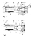
- FIG. 1 shows an embodiment of the ship coupling 1 according to the invention.
- the ship coupling 1 has a hydraulic cylinder 2 with a piston rod 5, a coupling rod 6 with a coupling element 11 and a housing 4 and an elastic element 3.
- the hydraulic cylinder 2 is arranged in the housing 4 and is pressed by the prestressed elastic element 3 in the axial direction against the housing 4, the prestressed elastic element 3 being arranged between the hydraulic cylinder 2 and the housing 4 in such a way that it is the hydraulic cylinder in the presses against the housing 4 away from the coupling rod 6.
- the restoring force of the prestressed elastic element 3 causes the hydraulic cylinder 2 to be held stationary in the housing 4 under normal load.
- the ship's coupling 1 is therefore able to dampen tensile and thrust loads between the ship's hull on which the ship's hull 1 is arranged and an adjacent ship's hull by the movement of the piston of the hydraulic cylinder 2 connected to the piston rod 5.
- Tension loads between the adjacent hulls, which are greater than the restoring force of the prestressed elastic element 3, are additionally damped by the elastic element 3. This prevents particularly large loads from being absorbed by the hydraulic cylinder 2 alone, so that damage to the hydraulic cylinder 2 is prevented.
- the elastic element is biased with a force of 5.89 ⁇ 10 5 N, which corresponds to the weight of a mass of 60 t.
- the piston rod 5 of the hydraulic cylinder 2 is connected to the coupling rod 6 via a connecting element 7, the connecting element 7 being fixedly connected to the piston rod 5 and engaging around the coupling rod 6 such that it can be rotated with respect to the piston rod 5.
- the connecting element 7 comprises a first section 9 firmly connected to the piston rod 5 and a flange 10 fastened to the first section 9. Between the first section 9 of the connecting element 7 and the flange 10 there is an end flange collar 8 of the coupling rod 6, so that the coupling rod 6 is rotatably received by the connecting element 7, but cannot move away from the piston rod 5 in the axial direction. Rotation of the coupling rod 6 is necessary in order to bring the coupling element 11 arranged at the end into engagement with the receiving element 12.
- the receiving element 12 is fixedly arranged on an adjacent hull and essentially comprises a plate 13 with a vertically extending recess 14 and a main body 15.
- the coupling rod 6 is rotated in this way that the coupling element 11 parallel to the recess 14 of the plate 13 is oriented and then the coupling element 11 is guided through the recess 14. Subsequently, the coupling rod 6 is rotated by 90 degrees, so that the coupling element 11 is oriented perpendicular to the direction of extension of the recess 14 and is thus in engagement.
- the coupling element 11 can now move along the recess 14, that is to say in the vertical direction, so that the two hulls coupled to one another can move vertically with respect to one another, as is the case due to wave movements.
- the two hulls can no longer move apart from one another in the coupled state, since the coupling element 11 of the coupling rod 6 abuts against the plate 13 of the receiving element 12 and cannot come loose from the receiving element 12 in the given orientation.
- the housing 4 which is fixedly connected to a hull, is received by two bearings 17, 18, which absorb forces acting on the housing.
- the bearings 17, 18 can be arranged in one or more brackets, which are firmly connected to the hull, but can be moved thereon, for example after loosening fastening screws or bolts.
- the ship's coupling 1 also has a shock absorption device 20.
- the shock absorbing device 20 comprises a main body 21, a plurality of damping elements 22 and a plurality of contact elements 23.
- the main body 21 is fixedly connected to the hull, so that it can absorb the forces acting between the adjacent hulls due to impacts.
- the base body 21 is made of a metal, such as steel.
- the contact elements 23 likewise consist of a metal, such as steel, and have a contact surface which comes into contact with the adjacent hulls in the event of impacts between the adjacent hulls.
- a damping element 22 is arranged between the base body 21 and the contact elements 23, which is made of rubber and is used to dampen the noise that results from collisions between the adjacent hulls.
- the base body 21 is arranged around the coupling rod 6 and has an opening 24 through which the coupling rod 6 is guided.
- a bearing 25 is arranged in the opening 24 and absorbs forces acting on the coupling rod 6 in the non-axial direction. Both the bearing 25 and the bearings 17, 18 are made of bronze.
- the contact elements 23 are connected to the base body 21 via bolts 26, the bolts 26 being guided through openings in the base body 21 and each having a bolt head whose cross-sectional area is larger than the cross-sectional area of the respective opening in the base body 21.
- the bolts 26 are welded or screwed to the contact elements 23.
- the bolts 26 hold the contact elements 23 in position in the vertical direction and allow a slight movement of the contact elements 23 in the axial direction, so that the contact elements 23 can transmit the impact on the damping elements 22, which are thereby compressed, when adjacent hulls collide.
- the contact elements 23 are also U-shaped in cross section, the two legs of the U-shape receiving the end faces of the base body 21, so that the legs of the U-shape of the contact elements 23 act as a guide for the relative movement between the base body 21 and the contact elements 23 serve.
- Figure 2 shows the ship's coupling 1 Figure 1 in disengaged condition.
- the coupling element 11 is oriented parallel to the recess 14 in the plate 13, so that the coupling element 11 can move through the recess 14 in the direction of the hydraulic cylinder 2.
- the decoupling process is ended by retracting the piston rod 5.
- a coupling process is carried out by moving the piston rod 5 out, the coupling element 11 moved through the recess 14 of the plate 13 of the receiving element 12.
- the coupling rod 6 is then rotated by 90 degrees, so that the coupling element 11 is oriented perpendicular to the direction of extent of the recess 14, as a result of which the coupling process is completed.
Landscapes
- Engineering & Computer Science (AREA)
- Chemical & Material Sciences (AREA)
- Combustion & Propulsion (AREA)
- Mechanical Engineering (AREA)
- Life Sciences & Earth Sciences (AREA)
- General Engineering & Computer Science (AREA)
- Ocean & Marine Engineering (AREA)
- Hydrology & Water Resources (AREA)
- Environmental & Geological Engineering (AREA)
- Water Supply & Treatment (AREA)
- Organic Chemistry (AREA)
- Fluid-Damping Devices (AREA)
- Shafts, Cranks, Connecting Bars, And Related Bearings (AREA)
- Actuator (AREA)
- Vibration Dampers (AREA)
Description
Schiffskupplung zur Verbindung zweier Schiffskörper, insbesondere eines schiebenden Fahrzeuges, beispielsweise eines Schubbootes, und eines geschobenen Fahrzeuges, beispielsweise eines Leichters, umfassend eine Kupplungsstange mit einem Kupplungselement und einen Hydraulikzylinder mit einer Kolbenstange, welche Zug- und Druckkräfte aufnimmt und in dem Hydraulikzylinder geführt ist, wobei die Kolbenstange und die Kupplungsstange miteinander verbunden sind.Ship coupling for connecting two hulls, in particular a pushing vehicle, for example a push boat, and a pushed vehicle, for example a lighter, comprising a coupling rod with a coupling element and a hydraulic cylinder with a piston rod, which absorbs tensile and compressive forces and is guided in the hydraulic cylinder, the piston rod and the coupling rod being connected to one another.
Die Erfindung betrifft dabei insbesondere eine Schiffskupplung zur Zusammenstellung eines Verbandes bestehend aus einem oder mehreren schiebenden Fahrzeugen und einem oder mehreren geschobenen Fahrzeugen, wobei die erfindungsgemäße Schiffskupplung sowohl zur Verbindung zweier schiebender Fahrzeuge als auch zur Verbindung zweier geschobener Fahrzeuge als auch zur Verbindung eines schiebenden Fahrzeuges und eines geschobenen Fahrzeuges vorgesehen ist. Mittels der erfindungsgemäßen Schiffskupplung können daher Schiffsverbände aus einem oder mehreren schiebenden Fahrzeugen und/oder einem oder mehreren geschobenen Fahrzeugen gebildet werden.The invention relates in particular to a ship coupling for assembling a group consisting of one or more pushing vehicles and one or more pushed vehicles, the ship coupling according to the invention both for connecting two pushing vehicles and for connecting two pushed vehicles and for connecting a pushing vehicle and a pushed vehicle is provided. By means of the ship coupling according to the invention, ship groups can therefore be formed from one or more pushing vehicles and / or one or more pushed vehicles.
Zum Transport großer Lasten auf dem Wasser werden insbesondere in der Binnenschifffahrt, aber auch in küstennahen Fahrgebieten, Schiffsverbände gebildet, die mehrere Schiffskörper umfassen. Bei zumindest einem der Schiffskörper eines solchen Schiffsverbandes handelt es sich um ein schiebendes Fahrzeug, beispielsweise um ein Schubboot oder einen Schlepper, und bei den übrigen Schiffskörpern um geschobene Fahrzeuge, beispielsweise sogenannte Leichter. Bei Leichtern handelt es sich um Schiffskörper ohne eigenen Hauptantrieb. Die Schiffskörper können durch Taue oder Drahtseile miteinander verbunden sein. Die Steuerung eines solchen Schiffsverbandes ist jedoch schwierig, wenn die geschobenen Fahrzeuge nicht mit Hilfsantrieben und Ruderwerken ausgestattet sind, sodass es leicht zu einem seitlichen Wegdriften der Leichter kommen kann. Darüber hinaus bewegen sich die Schiffskörper aufgrund der Wellenbewegung in allen sechs Freiheitsgraden gegeneinander. Bei den sechs Freiheitsgraden handelt es sich bekanntlich um drei Translations- und drei Rotationsfreiheitsgrade. Wird ein Schlepper zum Antrieb eines Schiffsverbandes verwendet, zieht dieser die Leichter hinter sich her. Bei Verwendung eines Schubbootes zum Antrieb eines Schiffsverbandes schiebt das Schubboot die Leichter vor sich her, sodass die Schubkraft von dem Rumpf des Schubbootes auf die Rümpfe der Leichter übertragen wird. Zur Übertragung der Schubkraft und der Kräfte, resultierend aus dem Manövriervermögen des Schubbootes auf einen Leichter werden Schiffskupplungen verwendet. Bei einem Verband mit zwei oder mehr Leichtern muss die Schubkraft zusätzlich von einem Leichter auf den anderen mittels einer Kupplung übertragen werden. Eine solche Kupplung muss die Kräfte auf den angrenzenden Schiffskörper übertragen, trotz der durch die Wellenbewegung verursachten unterschiedlichen Relativbewegungen der Schiffskörper gegeneinander in den sechs Freiheitsgraden. So kommt es bei einer Kurvenfahrt des Schiffsverbandes oder bei einem seitlichen Abdriften eines Schiffskörpers des Verbandes zu einer Neigung der Schiffskörper gegeneinander in einer horizontalen Ebene. Die Kupplung zwischen den Schiffskörpern muss darum auch eine solche Neigung der Schiffskörper gegeneinander zulassen.For the transport of large loads on the water, in particular in inland navigation, but also in coastal areas, ship associations are formed that comprise several hulls. At least one of the hulls of such a ship's association is a pushing vehicle, for example a push boat or a tug, and the other hulls are pushed vehicles, for example so-called lighters. Lighter are hulls without their own main drive. The hulls can be connected to each other by ropes or wire ropes. The control of such a ship association is however difficult if the pushed vehicles are not equipped with auxiliary drives and rudder mechanisms, so that the lighter can easily drift to the side. In addition, due to the wave motion, the hulls move against each other in all six degrees of freedom. As is well known, the six degrees of freedom are three degrees of translation and three degrees of rotation. If a tug is used to drive a ship's association, it pulls the lighter behind it. When using a push boat to propel a ship's association, the push boat pushes the lighter in front of it, so that the thrust is transferred from the hull of the push boat to the hulls of the lighter. Ship couplings are used to transmit the thrust and the forces resulting from the maneuverability of the push boat on a lighter. In a bandage with two or more lighters, the pushing force must also be transferred from one lighter to the other using a coupling. Such a coupling must transmit the forces to the adjacent hull, in spite of the different relative movements of the hulls against one another in the six degrees of freedom caused by the wave movement. Thus, when the ship's bundle is cornering or when a hull of the bundle drifts sideways, the hulls are inclined towards one another in a horizontal plane. The coupling between the hulls must therefore allow such an inclination of the hulls against each other.
Aus dem Stand der Technik sind Schiffskupplungen bekannt, welche einen oder mehrere Hydraulikzylinder aufweisen. So ist aus der
Aus der
Aus der
Die
Aus der Patentanmeldung
Aus der
Aufgabe der Erfindung ist es, eine Schiffskupplung mit Dämpfungswirkung zu schaffen, welche über zusätzliche Dämpfungsmittel zur Dämpfung von Lastspitzen verfügt.The object of the invention is to provide a ship coupling with a damping effect, which has additional damping means for damping peak loads.
Zur Lösung der Aufgabe wird eine Schiffskupplung vorgeschlagen, deren Hydraulikzylinder axial beweglich in einem unbeweglich mit einem Schiffskörper verbundenen Gehäuse gelagert ist, in welchem ein vorgespanntes elastisches Element angeordnet ist, dass den Hydraulikzylinder in seiner Axialrichtung gegen das Gehäuse drückt, sodass die Rückstellkraft des vorgespannten elastischen Elementes bewirkt, dass der Hydraulikzylinder bei Normallast ortsfest in dem Gehäuse gehalten wird und nur bei Lastspitzen, die größer sind als die Rückstellkraft des vorgespannten elastischen Elementes nimmt dieses einen Teil der Last auf. Weitere vorteilhafte Ausgestaltungen der Erfindung ergeben sich aus den Unteransprüchen.To solve the problem, a ship coupling is proposed, the hydraulic cylinder of which is axially movably mounted in a housing immovably connected to a hull, in which a prestressed elastic element is arranged that presses the hydraulic cylinder in its axial direction against the housing, so that the restoring force of the prestressed elastic Element causes the hydraulic cylinder to be held stationary in the housing under normal load and only at peak loads which are greater than the restoring force of the prestressed elastic element, this takes up part of the load. Further advantageous embodiments of the invention result from the subclaims.
Bei der erfindungsgemäßen Schiffskupplung werden zwei Dämpfungsglieder miteinander in vorteilhafter Weise kombiniert. Das vorgespannte elastische Element hält den Hydraulikzylinder innerhalb des Gehäuses bei Normallast in einer festen Position, sodass die Relativbewegung zwischen dem Schiffskörper, mit dem das Gehäuse der erfindungsgemäßen Schiffskupplung verbunden ist, und dem benachbarten Schiffskörper nur durch die Bewegung des Kolbens des Hydraulikzylinders und der mit ihm verbundenen Kolbenstange gedämpft wird. Bei Lastspitzen zwischen beiden Schiffskörpern, welche größer sind als die Rückstellkraft des vorgespannten elastischen Elementes, erfolgt die Dämpfung zusätzlich durch das elastische Element. Durch diese Ausbildung der erfindungsgemäßen Schiffskupplung kann ein Hydraulikzylinder zum Ankuppeln zweier Schiffskörper verwendet werden, ohne dass die Gefahr besteht, dass dieser bei Lastspitzen zerstört wird, was zu einem Verlust der Dämpfungsfähigkeit der Schiffskupplung durch Entweichen des in dem Hydraulikzylinders befindlichen Fluids oder zu einem Abtrennen der beiden Schiffskörper voneinander führen kann. Die mechanische Ankupplung beider Schiffskörper erfolgt durch die erfindungsgemäße Schiffskupplung mittels einer Kupplungsstange, welche einenends ein Kupplungselement aufweist und anderenends drehbar mit der Kolbenstange des Hydraulikzylinders verbunden ist. Das Kupplungselement weist eine Erstreckungsrichtung senkrecht zu der Erstreckungsrichtung der Kupplungsstange auf, wobei die Einkupplung beziehungsweise Entkupplung eines benachbarten Schiffskörpers durch Drehung der Kupplungsstange um jeweils 90 Grad erfolgt. Der benachbarte Schiffskörper weist zur Aufnahme des Kupplungselementes ein Aufnahmeelement auf, welches im Wesentlichen aus einer vertikal orientierten Platte mit einer sich vertikal erstreckenden Ausnehmung besteht. Bei vertikaler Orientierung des Kupplungselementes kann dieses durch die Ausnehmung der Platte geschoben und sodann über Drehung der Kupplungsstange um 90 Grad verdreht werden, sodass eine rückwärtige Bewegung des Kupplungselementes durch die Ausnehmung der Platte des Aufnahmeelementes verhindert wird. Die sich vertikal erstreckende Ausnehmung erlaubt darüber hinaus eine vertikale Relativbewegung der Kupplungsstange einerseits und des Aufnahmeelementes andererseits und folglich eine vertikale Relativbewegung der beiden benachbarten Schiffskörper zueinander.In the ship coupling according to the invention, two attenuators are advantageously combined with one another. The prestressed elastic element holds the hydraulic cylinder within the housing in normal load in a fixed position, so that the relative movement between the hull to which the housing of the ship coupling according to the invention is connected and the adjacent hull only by the movement of the piston of the hydraulic cylinder and with it connected piston rod is damped. At peak loads between the two hulls, which are greater than the restoring force of the prestressed elastic element, the damping is additionally carried out by the elastic element. As a result of this design of the ship coupling according to the invention, a hydraulic cylinder can be used for coupling two ship hulls without the risk that this is destroyed at peak loads, which can lead to a loss in the damping capacity of the ship's coupling due to the escape of the fluid in the hydraulic cylinder or to a separation of the two hulls from one another. The mechanical coupling of both hulls takes place through the ship coupling according to the invention by means of a coupling rod which has a coupling element at one end and is rotatably connected at the other end to the piston rod of the hydraulic cylinder. The coupling element has a direction of extension perpendicular to the direction of extension of the coupling rod, with the coupling or uncoupling of an adjacent hull being effected by rotating the coupling rod by 90 degrees in each case. The adjacent hull has a receiving element for receiving the coupling element, which essentially consists of a vertically oriented plate with a vertically extending recess. When the coupling element is oriented vertically, it can be pushed through the recess in the plate and then rotated by rotating the coupling rod by 90 degrees, so that a rearward movement of the coupling element through the recess in the plate of the receiving element is prevented. The vertically extending recess also allows a vertical relative movement of the coupling rod on the one hand and the receiving element on the other hand and consequently a vertical relative movement of the two adjacent hulls to each other.
Die erfindungsgemäße Kupplung ermöglicht eine tiefgangsunabhängige Verbindung der schiebenen und geschobenen Fahrzeuge untereinander, wobei die horizontalen Kupplungsebenen zwischen den schiebenen und geschobenen Fahrzeugen zueinander variabel sind.The coupling according to the invention enables a connection of the pushed and pushed vehicles independently of one another, the horizontal coupling levels between the pushed and pushed vehicles being variable with respect to one another.
Um Spannungen auf das Gehäuse bei einer Relativbewegung der beiden gekoppelten Schiffskörper zu vermeiden, ist in Ausgestaltung der Erfindung vorgesehen, dass das Gehäuse um eine horizontale Achse schwenkbeweglich gelagert ist. Eine solche Lagerung wird beispielsweise dadurch erreicht, dass das Gehäuse zwei seitliche, einstückig angeformte Lagerbolzen aufweist, die jeweils in einem Lager aufgenommen sind, wobei die Lager unbeweglich mit einem Schiffskörper verbunden sind.In order to avoid tension on the housing during a relative movement of the two coupled hulls, it is provided in an embodiment of the invention that the housing can be pivoted about a horizontal axis is stored. Such storage is achieved, for example, in that the housing has two lateral, integrally formed bearing bolts, which are each received in a bearing, the bearings being immovably connected to a hull.
In weiterer Ausgestaltung der erfindungsgemäßen Schiffskupplung kann vorgesehen sein, dass das elastische Element den Hydraulikzylinder in die von der Kupplungsstange abgewandte Richtung drückt. Durch diese Orientierung der Rückstellkraft des vorgespannten elastischen Elementes können Zuglastspitzen durch das elastische Element gedämpft werden, also ungewöhnlich große Kräfte, die auf ein Entfernen der beiden Schiffskörper voneinander hinwirken. Natürlich kann auch vorgesehen sein, dass das elastische Element den Hydraulikzylinder in die der Kupplungsstange zugewandte Richtung drückt, wodurch die Rückstellkraft des vorgespanten elastischen Elementes in Richtung der Kupplungsstange orientiert ist. In dieser Ausgestaltung können Schublastspitzen, also ungewöhnlich große Kräfte, die auf eine Annäherung der beiden Schiffskörper hinwirken, durch das elastische Element gedämpft werden.In a further embodiment of the marine coupling according to the invention it can be provided that the elastic element presses the hydraulic cylinder in the direction facing away from the coupling rod. Due to this orientation of the restoring force of the prestressed elastic element, tensile load peaks can be damped by the elastic element, that is, unusually large forces which act to remove the two hulls from one another. Of course, it can also be provided that the elastic element presses the hydraulic cylinder in the direction facing the coupling rod, as a result of which the restoring force of the preloaded elastic element is oriented in the direction of the coupling rod. In this embodiment, drawer load tips, that is to say unusually large forces which act towards the two hulls coming closer, can be damped by the elastic element.
Bevorzugt ist, dass das elastische Element durch eine Kraft von 5·105 N oder mehr vorgespannt ist. Dies bedeutet, dass das elastische Element nur Kräfte von 5·105 N oder mehr zwischen den benachbarten Schiffskörpern dämpft. Selbstverständlich kann das elastische Element auch mit einer anderen Kraft aufgespannt werden, also eine andere Rückstellkraft aufweisen. Dies hängt von dem jeweiligen Anwendungsfall, also dem zu erwartenden Seegang, der Schubkraft des Schubbootes beziehungsweise des Schleppers und der Masse der zu verbindenden Schiffskörper, ab. Eine Kraft von 5·105 N entspricht der Gewichtskraft einer Masse von 50,97 Tonnen.It is preferred that the elastic element is prestressed by a force of 5 · 10 5 N or more. This means that the elastic element only dampens forces of 5 · 10 5 N or more between the adjacent hulls. Of course, the elastic element can also be clamped with a different force, that is to say have a different restoring force. This depends on the respective application, i.e. the expected swell, the thrust of the push boat or the tug and the mass of the hull to be connected. A force of 5 · 10 5 N corresponds to the weight of a mass of 50.97 tons.
Die erfindungsgemäße Schiffskupplung kann derart ausgestaltet werden, dass die Kolbenstange und die Kupplungsstange durch ein Verbindungselement miteinander verbunden sind, welches fest mit der Kolbenstange verbunden ist und einen Flanschkragen der Kupplungsstange umgreift, sodass die Kupplungsstange drehbar von dem Verbindungselement aufgenommen ist. Der Flanschkragen der Kupplungsstange kann dabei endseitig oder an anderer Stelle an der Kupplungsstange angeordnet sein. Diese Ausbildung der Schiffskupplung bewirkt, dass die zum Einkuppeln des Kupplungselementes in das Aufnahmeelement des benachbarten Schiffskörpers nötige Drehung der Kupplungsstange allein von dieser ausgeführt wird, wohingegen die Kolbenstange keine Drehung ausführt. Dazu ist das Verbindungselement fest mit der Kolbenstange verbunden und umgreift einen Flanschkragen der Kupplungsstange, sodass letztere durch das Verbindungselement zwar unlösbar mit der Kolbenstange verbunden ist, jedoch Drehungen ausführen kann.The ship coupling according to the invention can be designed such that the piston rod and the coupling rod by a connecting element are interconnected, which is fixedly connected to the piston rod and engages around a flange collar of the coupling rod, so that the coupling rod is rotatably received by the connecting element. The flange collar of the coupling rod can be arranged at the end or at another location on the coupling rod. This design of the ship's coupling has the effect that the rotation of the coupling rod necessary for coupling the coupling element into the receiving element of the adjacent ship's hull is carried out by the latter alone, whereas the piston rod does not rotate. For this purpose, the connecting element is fixedly connected to the piston rod and engages around a flange collar of the coupling rod, so that the latter is inseparably connected to the piston rod by the connecting element, but can make rotations.
Weiterhin kann die Kupplungsstange vorteilhaft in zumindest einem ersten Lager gelagert sein, welches Bewegungen der Kupplungsstange in nicht-axialer Richtung verhindert und dabei Kräfte, die in nicht-axialer Richtung auf die Kupplungsstange wirken, aufnimmt. Das erste Lager bewirkt, dass die Kupplungsstange und dadurch auch die Kolbenstange, Bewegungen ausschließlich in axialer Richtung ausführen, was insbesondere verhindert, dass der Hydraulikzylinder beschädigt wird. Das erste Lager kann zumindest an der der Kupplungsstange zugewandten Oberfläche aus Bronze oder vollständig aus Bronze bestehen. Ferner kann auch das Gehäuse der erfindungsgemäßen Schiffskupplung über zumindest ein zweites Lager mit dem Schiffskörper verbunden sein. Dieses zweite Lager nimmt die über die Kupplungsstange und die Kolbenstange auf das Gehäuse übertragenen Kräfte auf. Auch das zweite Lager kann zumindest an der dem Gehäuse zugewandten Oberfläche oder vollständig aus Bronze bestehen.Furthermore, the coupling rod can advantageously be mounted in at least one first bearing which prevents movements of the coupling rod in the non-axial direction and thereby absorbs forces which act on the coupling rod in the non-axial direction. The first bearing causes the coupling rod and thereby also the piston rod to execute movements exclusively in the axial direction, which in particular prevents the hydraulic cylinder from being damaged. The first bearing can be made of bronze or completely of bronze at least on the surface facing the coupling rod. Furthermore, the housing of the ship's coupling according to the invention can also be connected to the ship's hull via at least one second bearing. This second bearing absorbs the forces transmitted to the housing via the coupling rod and the piston rod. The second bearing can also consist of bronze at least on the surface facing the housing or entirely.
In weiterer Ausgestaltung der erfindungsgemäßen Schiffskupplung kann vorgesehen sein, dass diese eine Stoßdämpfungsvorrichtung umfasst, welche einen Grundkörper, wenigstens ein Kontaktelement mit einer einem benachbarten Schiffskörper zugewandten Kontaktfläche und wenigstens ein nichtmetallisches Dämpfungselement umfasst, wobei das Dämpfungselement zwischen dem Grundkörper und dem Kontaktelement angeordnet ist, und der Grundkörper fest mit einem Schiffskörper verbunden ist. Entgegen der aus dem Stand der Technik bekannten Stoßdämpfungsvorrichtungen für Schiffskupplungen besteht die Stoßdämpfungsvorrichtung gemäß dieser Weiterbildung der erfindungsgemäßen Schiffskupplung nicht ausschließlich aus einem Metall, sondern weist ein nichtmetallisches Dämpfungselement auf. Das nichtmetallische Dämpfungselement bewirkt im Wesentlichen eine Dämpfung der Geräuschentwicklung bei Aufeinanderstoßen des Kontaktelementes der Stoßdämpfungsvorrichtung mit einem benachbarten Schiffskörper, insbesondere dem Aufnahmeelement eines benachbarten Schiffskörpers für ein Kupplungselement einer Schiffskupplung. Das Dämpfungselement kann aus einem elastischen Material, wie Gummi oder einem elastischen Kunststoff, oder aus einem anderen nichtmetallischen Material, wie einem nichtelastischen Kunststoff bestehen. Das Kontaktelement und/oder der Grundkörper können dagegen aus einem Metall bestehen, sodass das Dämpfungselement auch bei großen Kraftüberträgen infolge von Stoßvorgängen nicht verformt oder beschädigt wird.In a further embodiment of the ship coupling according to the invention it can be provided that it comprises a shock absorbing device which has a base body, at least one contact element with an adjacent one Hull facing contact surface and at least one non-metallic damping element, wherein the damping element is arranged between the base body and the contact element, and the base body is fixedly connected to a hull. Contrary to the shock absorbing devices for ship couplings known from the prior art, the shock absorbing device according to this development of the ship coupling according to the invention does not consist exclusively of a metal, but has a non-metallic damping element. The non-metallic damping element essentially effects a damping of the noise development when the contact element of the shock absorbing device collides with an adjacent hull, in particular the receiving element of an adjacent hull for a coupling element of a hull. The damping element can consist of an elastic material, such as rubber or an elastic plastic, or of another non-metallic material, such as a non-elastic plastic. The contact element and / or the base body, on the other hand, can consist of a metal, so that the damping element is not deformed or damaged even with large force transmissions as a result of impact processes.
Weiterhin kann die erfindungsgemäße Schiffskupplung dahingehend ausgestaltet werden, dass das Kontaktelement über einen axial geführten Bolzen mit dem Grundkörper derart verbunden ist, dass das Kontaktelement relativ zu dem Grundkörper beweglich ist. In dieser Ausgestaltung ist der Grundkörper ein starres Gebilde, welcher fest mit einem Schiffskörper verbunden ist und mit dem das Kontaktelement über einen axial geführten Bolzen beweglich verbunden ist. Durch die axiale Beweglichkeit des Kontaktelementes kann das Dämpfungselement bei Stoßeinwirkung komprimiert werden und anschließend seine ursprüngliche Form wieder annehmen. Das Dämpfungselement kann einseitig entweder mit einer Stirnfläche des Grundkörpers oder mit einer der Kontaktfläche abgewandten Fläche des Kontaktelementes verbunden, beispielsweise verklebt, sein. In besonderer Ausgestaltung des Kontaktelementes ist dieses im Querschnitt U-förmig, wobei in der Vertiefung der U-Form das Dämpfungselement angeordnet ist. Die Schenkel der U-Form können sich dabei so weit in Richtung des Grundkörpers erstrecken, dass die Stirnfläche des Grundkörpers, mit welcher das Dämpfungselement in Kontakt gerät, von den Schenkeln eingefasst ist. Der axial geführte Bolzen kann einenends fest mit dem Kontaktelement verbunden und in einem Durchbruch des Grundkörpers gelagert sein und anderenends einen Bolzenkopf aufweisen, dessen Querschnittsfläche größer ist, als die Querschnittsfläche des Durchbruches. Dabei bewirkt die Ausbildung des Bolzenkopfes mit einer Querschnittsfläche, die größer ist als die Querschnittsfläche des Durchbruches in dem Grundkörper, dass sich der Bolzen nicht von dem Grundkörper lösen kann und sich das Kontaktelement dadurch in axialer Richtung bewegen kann, ohne jemals vollständig von dem Grundkörper gelöst zu werden.Furthermore, the ship coupling according to the invention can be designed such that the contact element is connected to the base body via an axially guided bolt in such a way that the contact element is movable relative to the base body. In this embodiment, the base body is a rigid structure which is fixedly connected to a hull and to which the contact element is movably connected via an axially guided bolt. Due to the axial mobility of the contact element, the damping element can be compressed when subjected to an impact and then assume its original shape again. The damping element can be connected on one side either to an end face of the base body or to a face of the contact element facing away from the contact face, for example glued. In a special embodiment of the contact element, this is U-shaped in cross-section, the damping element being arranged in the recess of the U-shape. The legs of the U-shape can extend so far in the direction of the base body that the end face of the base body, with which the damping element comes into contact, is surrounded by the legs. The axially guided bolt can at one end be fixedly connected to the contact element and be mounted in an opening in the base body and at the other end have a bolt head whose cross-sectional area is larger than the cross-sectional area of the opening. The design of the bolt head with a cross-sectional area that is larger than the cross-sectional area of the opening in the base body means that the bolt cannot detach from the base body and the contact element can thereby move in the axial direction without ever being completely detached from the base body to become.
Der Grundkörper der Stoßdämpfungsvorrichtung der erfindungsgemäßen Schiffskupplung kann so ausgestaltet sein, dass er eine Öffnung aufweist, in welcher die Kupplungsstange der Schiffskupplung geführt ist. In dieser Ausgestaltung ist der Grundkörper der Stoßdämpfungsvorrichtung um die Kupplungsstange herum angeordnet, sodass der Grundkörper nicht nur die Funktion der Stoßaufnahme, sondern auch der Führung der Kupplungsstange erfüllt. Bei dieser Ausgestaltung der Stoßdämpfungsvorrichtung ist sichergestellt, dass es nur im Bereich der Kupplungsverbindung, welche zumeist zentral an dem Bug oder Heck eines Schiffskörpers angeordnet ist, zu einem Berührungskontakt benachbarter Schiffskörper kommt, wodurch eine Berührung der Schiffskörper abseits der Kupplungsverbindung verhindert wird.The base body of the shock absorbing device of the ship's coupling according to the invention can be designed such that it has an opening in which the coupling rod of the ship's coupling is guided. In this embodiment, the base body of the shock absorbing device is arranged around the coupling rod, so that the base body not only fulfills the function of absorbing the shock, but also of guiding the coupling rod. In this embodiment of the shock absorbing device, it is ensured that only in the area of the coupling connection, which is usually arranged centrally on the bow or stern of a hull, there is contact between adjacent hulls, thereby preventing the hulls from touching the coupling connection.
In weiterer Ausgestaltung der Stoßdämpfungsvorrichtung der Schiffskupplung, welche einen Grundkörper mit einer Öffnung aufweist, in der die Kupplungsstange geführt ist, kann vorgesehen sein, dass das erste Lager zur axialen Führung der Kupplungsstange in der Öffnung des Grundkörpers angeordnet ist. Dadurch wird vorteilhafterweise erreicht, dass keine zusätzliche Halterung für das erste Lager an dem Schiffskörper befestigt werden muss.In a further embodiment of the shock-absorbing device of the ship's coupling, which has a base body with an opening in which the coupling rod is guided, it can be provided that the first bearing for axially guiding the coupling rod is arranged in the opening of the base body. This advantageously means that no additional holder for the first bearing has to be attached to the hull.
Unter axialer Richtung oder Axialrichtung wird im Kontext dieser Anmeldung stets eine bezüglich der Schiffskupplung zentral gelegene sich in die Haupterstreckungsrichtung der Schiffskupplung erstreckende Achse bezeichnet.In the context of this application, the term axial direction or axial direction always denotes an axis which is centrally located with respect to the ship's coupling and extends in the main direction of extent of the ship's coupling.
Die Erfindung wird im Weiteren anhand der Figuren näher erläutert.The invention is explained in more detail below with reference to the figures.
Es zeigt
- Fig. 1
- eine horizontale Querschnittsansicht einer Ausführungsform einer erfindungsgemäßen Schiffskupplung in einem eingekuppelten Zustand und
- Fig. 2
- eine horizontale Querschnittsansicht der Ausführungsform der erfindungsgemäßen Schiffskupplung in einem ausgekuppelten Zustand.
- Fig. 1
- a horizontal cross-sectional view of an embodiment of a ship's coupling according to the invention in a coupled state and
- Fig. 2
- a horizontal cross-sectional view of the embodiment of the ship's coupling according to the invention in a disengaged state.
Die Kolbenstange 5 des Hydraulikzylinders 2 ist über ein Verbindungselement 7 mit der Kupplungsstange 6 verbunden, wobei das Verbindungselement 7 fest mit der Kolbenstange 5 verbunden ist und die Kupplungsstange 6 derart umgreift, dass diese bezüglich der Kolbenstange 5 drehbar ist. Das Verbindungselement 7 umfasst ein erstes mit der Kolbenstange 5 fest verbundenes Teilstück 9 und einen mit dem ersten Teilstück 9 befestigten Flansch 10. Zwischen dem ersten Teilstück 9 des Verbindungselementes 7 und dem Flansch 10 ist ein endseitiger Flanschkragen 8 der Kupplungsstange 6 angeordnet, sodass die Kupplungsstange 6 drehbar von dem Verbindungselement 7 aufgenommen ist, sich jedoch in axialer Richtung nicht von der Kolbenstange 5 entfernen kann. Das Verdrehen der Kupplungsstange 6 ist erforderlich, um das endseitig angeordnete Kupplungselement 11 mit dem Aufnahmeelement 12 in Eingriff zu bringen. Das Aufnahmeelement 12 ist fest an einem benachbarten Schiffskörper angeordnet und umfasst im Wesentlichen eine Platte 13 mit einer sich vertikal erstreckenden Ausnehmung 14 und einen Hauptkörper 15. Zur Einkupplung des Kupplungselementes 11 der Schiffskupplung 1 in das Aufnahmeelement 12 eines benachbarten Schiffskörpers wird die Kupplungsstange 6 derart gedreht, dass das Kupplungselement 11 parallel zu der Ausnehmung 14 der Platte 13 orientiert ist und sodann wird das Kupplungselement 11 durch die Ausnehmung 14 geführt. Anschließend wird die Kupplungsstange 6 um 90 Grad verdreht, sodass das Kupplungselement 11 senkrecht zur Erstreckungsrichtung der Ausnehmung 14 orientiert ist und sich somit in Eingriff befindet. Das Kupplungselement 11 kann sich nun entlang der Ausnehmung 14, also in vertikaler Richtung, bewegen, sodass die beiden aneinander gekuppelten Schiffskörper sich gegeneinander vertikal bewegen können, wie dies aufgrund von Wellenbewegungen der Fall ist. Dagegen können sich die beiden Schiffskörper in eingekuppeltem Zustand nicht mehr voneinander entfernen, da das Kupplungselement 11 der Kupplungsstange 6 gegen die Platte 13 des Aufnahmeelementes 12 stößt und sich bei der gegebenen Orientierung nicht aus dem Aufnahmeelement 12 lösen kann.The
Das fest mit einem Schiffskörper verbundene Gehäuse 4 ist von zwei Lagern 17, 18 aufgenommen, welche auf das Gehäuse wirkende Kräfte aufnehmen. Die Lager 17, 18 können in einer oder mehr Halterungen angeordnet sein, welche zwar mit dem Schiffskörper fest verbunden sind, jedoch auf diesem versetzt werden können, zum Beispiel nach dem Lösen von Befestigungsschrauben oder Bolzen.The housing 4, which is fixedly connected to a hull, is received by two
Die erfindungsgemäße Schiffskupplung 1 weist ferner eine Stoßdämpfungsvorrichtung 20 auf. Die Stoßdämpfungsvorrichtung 20 umfasst einen Grundkörper 21, mehrere Dämpfungselemente 22 und mehrere Kontaktelemente 23. Der Grundkörper 21 ist mit dem Schiffskörper fest verbunden, sodass er aufgrund von Stößen zwischen den benachbarten Schiffskörpern einwirkende Kräfte aufnehmen kann. Der Grundkörper 21 besteht aus einem Metall, wie zum Beispiel Stahl. Die Kontaktelemente 23 bestehen ebenfalls aus einem Metall, wie zum Beispiel Stahl, und weisen eine Kontaktfläche auf, welche bei Stößen zwischen den benachbarten Schiffskörpern in Berührungskontakt mit den benachbarten Schiffskörpern gerät. Zwischen dem Grundkörper 21 und den Kontaktelementen 23 ist jeweils ein Dämpfungselement 22 angeordnet, welches aus Gummi besteht und dazu dient, die sich bei Zusammenstößen zwischen den benachbarten Schiffskörpern ergebende Geräuschentwicklung zu dämpfen. Der Grundkörper 21 ist um die Kupplungsstange 6 herum angeordnet und weist eine Öffnung 24 auf, durch welche die Kupplungsstange 6 geführt ist. In der Öffnung 24 ist ein Lager 25 angeordnet, welches in nicht axialer Richtung auf die Kupplungsstange 6 wirkende Kräfte aufnimmt. Sowohl das Lager 25 als auch die Lager 17, 18 bestehen aus Bronze.The ship's
Die Kontaktelemente 23 sind über Bolzen 26 mit dem Grundkörper 21 verbunden, wobei die Bolzen 26 durch Durchbrüche in dem Grundkörper 21 geführt sind und jeweils einen Bolzenkopf aufweisen, dessen Querschnittsfläche größer ist als die Querschnittsfläche des jeweiligen Durchbruches in dem Grundkörper 21. Die Bolzen 26 sind mit den Kontaktelementen 23 verschweißt oder verschraubt. Die Bolzen 26 halten die Kontaktelemente 23 in vertikaler Richtung in Position und erlauben in axialer Richtung eine geringfügige Bewegung der Kontaktelemente 23, sodass die Kontaktelemente 23 bei einem Aneinanderstoßen benachbarter Schiffskörper die Stoßwirkung auf die Dämpfungselemente 22, welche dadurch komprimiert werden, übertragen können. Die Kontaktelemente 23 sind ferner im Querschnitt U-förmig ausgebildet, wobei die beiden Schenkel der U-Form die Stirnflächen des Grundkörpers 21 aufnehmen, sodass die Schenkel der U-Form der Kontaktelemente 23 als Führung für die Relativbewegung zwischen dem Grundkörper 21 und den Kontaktelementen 23 dienen.The
- 11
- SchiffskupplungShip coupling
- 22nd
- HydraulikzylinderHydraulic cylinder
- 33rd
- elastisches Elementelastic element
- 44th
- Gehäusecasing
- 55
- KolbenstangePiston rod
- 66
- KupplungsstangeClutch rod
- 77
- VerbindungselementFastener
- 88th
- FlanschkragenFlange collar
- 99
- TeilstückSection
- 1010th
- Flanschflange
- 1111
- KupplungselementCoupling element
- 1212
- AufnahmeelementReceiving element
- 1313
- Platteplate
- 1414
- AusnehmungRecess
- 1515
- HauptkörperMain body
- 1717th
- Lagerwarehouse
- 1818th
- Lagerwarehouse
- 2020th
- StoßdämpfungsvorrichtungShock absorbing device
- 2121st
- GrundkörperBasic body
- 2222
- DämpfungselementeDamping elements
- 2323
- KontaktelementeContact elements
- 2424th
- Öffnungopening
- 2525th
- Lagerwarehouse
- 2626
- Bolzenbolt
Claims (15)
- Ship coupling (1) for connecting two ship hulls, in particular a pushing vehicle and a pushed vehicle, comprising a coupling rod (6) with a coupling element (11) and a hydraulic cylinder (2) with a piston rod (5) guided in the hydraulic cylinder (2), wherein the piston rod (5) and the coupling rod (6) are connected to each other,
characterized in
that the hydraulic cylinder (2) is mounted, in an axially movable manner, in a housing (4) connected to a ship hull, a prestressed elastic element (3) being disposed in the housing and pushing the hydraulic cylinder (2) in its axial direction against the housing (4) such that the restoring force of the prestressed elastic element (3) causes the hydraulic cylinder (2) to be stationarily held in the housing at normal load, and only at peak loads that are greater than the restoring force of the prestressed elastic element (3), it absorbs a part of the load. - Ship coupling (1) according to claim 1,
characterized in
that the housing (4) is pivoted about a horizontal axis. - Ship coupling (1) according to claim 1 or 2,
characterized in
that the elastic element (3) pushes the hydraulic cylinder (2) into the direction facing away from the coupling rod (6) or in a direction towards the coupling rod (6). - Ship coupling (1) according to one of claims 1, 2 or 3,
characterized in
that the elastic element (3) exerts a force of 5·105 N or more onto the hydraulic cylinder (2). - Ship coupling (1) according to one of claims 1 to 4,
characterized in
that the piston rod (5) and the coupling rod (6) are connected to each other via a connecting element (7) which is firmly connected with the piston rod (5) and grips around a flange collar (8) of the coupling rod (6) such that the coupling rod (6) is rotatably received by the connecting element (7). - Ship coupling (1) according to one of claims 1 to 5,
characterized in
that the coupling rod (6) is mounted in at least one first bearing (25) which prevents movements of the coupling rod (6) in a non-axial direction. - Ship coupling (1) according to claim 6,
characterized in
that the first bearing (25) consists, at least at the surface facing the coupling rod (6), of bronze, or that the first bearing (25) completely consists of bronze. - Ship coupling (1) according to one of claims 1 to 7,
characterized in
that the housing (4) is connected to the ship hull via at least one second bearing (17, 18). - Ship coupling (1) according to claim 8,
characterized in
that the second bearing (17, 18) consists, at least at the surface facing the housing (4), of bronze, or that the second bearing (17, 18) completely consists of bronze. - Ship coupling (1) according to one of claims 1 to 9,
characterized in
that the ship coupling (1) comprises a shock-absorbing device (20) comprising a basic body (21), at least one contact element (23) with a contact surface facing an adjacent ship hull, and at least one non-metallic absorbing element (22), wherein the absorbing element (22) is disposed between the basic body (21) and the contact element (23), and the basic body (21) is firmly connected with a ship hull. - Ship coupling (1) according to claim 10,
characterized in
that the absorbing element (22) consists of an elastic material, and/or that the absorbing element (22) consists of rubber or a plastic. - Ship coupling (1) according to one or several ones of claims 10 to 11,
characterized in
that the contact element (23) and/or the basic body (21) consist(s) of a metal. - Ship coupling (1) according to one or several ones of claims 10 to 12,
characterized in
that the contact element (23) is connected to the basic body (21) via an axially guided pin (26) such that the contact element (23) is movable relative to the basic body (21). - Ship coupling (1) according to claim 13,
characterized in
that the pin (26) is at one end firmly connected with the contact element (23) and at the other end comprises a pin head, wherein the pin (26) is mounted in a hole of the basic body (21) the cross-sectional area of which is larger than the cross-sectional area of the hole. - Ship coupling (1) according to one or several ones of claims 10 to 14,
characterized in
that the basic body (21) has an opening (26) in which the coupling rod (6) is guided, and/or that the first bearing (25) is disposed in the opening (24) of the basic body (21).
Priority Applications (1)
| Application Number | Priority Date | Filing Date | Title |
|---|---|---|---|
| PL14001790T PL2818397T3 (en) | 2013-05-22 | 2014-05-21 | Ship coupling for connecting two ship bodies |
Applications Claiming Priority (2)
| Application Number | Priority Date | Filing Date | Title |
|---|---|---|---|
| DE102013008596.9A DE102013008596A1 (en) | 2013-05-22 | 2013-05-22 | Ship coupling for connecting two hulls |
| DE202013005213U DE202013005213U1 (en) | 2013-05-22 | 2013-05-22 | Ship coupling for connecting two hulls |
Publications (3)
| Publication Number | Publication Date |
|---|---|
| EP2818397A2 EP2818397A2 (en) | 2014-12-31 |
| EP2818397A3 EP2818397A3 (en) | 2015-04-08 |
| EP2818397B1 true EP2818397B1 (en) | 2020-06-03 |
Family
ID=50828653
Family Applications (1)
| Application Number | Title | Priority Date | Filing Date |
|---|---|---|---|
| EP14001790.6A Active EP2818397B1 (en) | 2013-05-22 | 2014-05-21 | Ship coupling for connecting two ship bodies |
Country Status (4)
| Country | Link |
|---|---|
| EP (1) | EP2818397B1 (en) |
| DE (1) | DE202013005213U1 (en) |
| DK (1) | DK2818397T3 (en) |
| PL (1) | PL2818397T3 (en) |
Family Cites Families (6)
| Publication number | Priority date | Publication date | Assignee | Title |
|---|---|---|---|---|
| US3882813A (en) | 1970-01-17 | 1975-05-13 | Weser Dt197001172001996 Ag | Watercraft coupling system |
| US3990386A (en) * | 1975-05-23 | 1976-11-09 | The United States Of America As Represented By The Secretary Of The Navy | Faired multi-strength member towcable and associated sequential load distribution system |
| JPS51141192A (en) * | 1975-05-29 | 1976-12-04 | Ishikawajima Zosen Kakoki Kk | Adsorber used for ships and the like |
| ZA755386B (en) | 1975-08-22 | 1977-04-27 | Rytac Ltd | A coupling device |
| DE3123709C2 (en) * | 1981-06-15 | 1983-10-13 | Heinrich 4130 Moers Harbisch | Axially sprung coupling rod for push boat units lying next to one another |
| DE10259532A1 (en) | 2002-12-19 | 2004-07-01 | Daimlerchrysler Ag | Support bearing of a vibration-damping element |
-
2013
- 2013-05-22 DE DE202013005213U patent/DE202013005213U1/en not_active Expired - Lifetime
-
2014
- 2014-05-21 EP EP14001790.6A patent/EP2818397B1/en active Active
- 2014-05-21 PL PL14001790T patent/PL2818397T3/en unknown
- 2014-05-21 DK DK14001790.6T patent/DK2818397T3/en active
Non-Patent Citations (1)
| Title |
|---|
| None * |
Also Published As
| Publication number | Publication date |
|---|---|
| EP2818397A3 (en) | 2015-04-08 |
| DE202013005213U1 (en) | 2013-07-16 |
| PL2818397T3 (en) | 2020-11-30 |
| EP2818397A2 (en) | 2014-12-31 |
| DK2818397T3 (en) | 2020-09-07 |
Similar Documents
| Publication | Publication Date | Title |
|---|---|---|
| EP1916181B1 (en) | Coupling between two articulated vehicle parts, e.g. for an articulated vehicle | |
| DE2451501A1 (en) | DEVICE FOR MOORING WATER VEHICLES | |
| DE102010037180A1 (en) | Spring device for use as component of stabilizer in adjustor utilized for adjusting chassis of e.g. motor car, has tubular carrier arranged coaxial to torsion bar spring for retaining and/or dissipating bending forces | |
| DE1531735B2 (en) | Push coupling for a push convoy consisting of a push vehicle and a barge | |
| DE102020210860A1 (en) | Multi-part spring for a ball screw | |
| EP4326595B1 (en) | Draw and buffer gear for a railway coupling, and railway coupling | |
| EP3459828B1 (en) | Device for the transmission of forces in the event of a crash of a motor vehicle | |
| DE102009053369B4 (en) | Motor vehicle | |
| DE102012204059B3 (en) | Shock absorber for storing an object in or on a vehicle | |
| DE102009052371A1 (en) | Vehicle, has energy storage device with set of energy storage units, which are arranged and/or designed such that energy storage units are movable and/or deformable in non-destructive manner by force effect on vehicle | |
| EP2818397B1 (en) | Ship coupling for connecting two ship bodies | |
| DE102010040840A1 (en) | Multi-part rail vehicle with at least two car bodies connected by a double joint | |
| DE1809135C3 (en) | ||
| EP1935780A2 (en) | Extension device | |
| DE102017213312A1 (en) | Vehicle seat console | |
| DE102017002211A1 (en) | Distance element for use in a holding arrangement, holding arrangement and this holding arrangement comprehensive vehicle | |
| DE102013008596A1 (en) | Ship coupling for connecting two hulls | |
| AT502758B1 (en) | CRASH ELEMENT FOR RECEIVING OVERSIZED IMPACT ON THE SUPPORT STRUCTURE OF A VEHICLE BOOT BASE OF A RAIL VEHICLE | |
| DE102010021859B4 (en) | Braking and / or locking device of a slide movable on a rail | |
| AT527944B1 (en) | Impact device | |
| EP2874871B1 (en) | Device for mounting a marine engine on an engine pedestal | |
| EP3771609A1 (en) | Sleeve buffer with partially sheathed tappet | |
| DE2123743C3 (en) | Suspension for vehicles, in particular trucks | |
| DE3123709C2 (en) | Axially sprung coupling rod for push boat units lying next to one another | |
| DE1605074B2 (en) | PIVOT BEARINGS, IN PARTICULAR FOR BOGIES OF RAIL VEHICLES |
Legal Events
| Date | Code | Title | Description |
|---|---|---|---|
| PUAI | Public reference made under article 153(3) epc to a published international application that has entered the european phase |
Free format text: ORIGINAL CODE: 0009012 |
|
| 17P | Request for examination filed |
Effective date: 20140521 |
|
| AK | Designated contracting states |
Kind code of ref document: A2 Designated state(s): AL AT BE BG CH CY CZ DE DK EE ES FI FR GB GR HR HU IE IS IT LI LT LU LV MC MK MT NL NO PL PT RO RS SE SI SK SM TR |
|
| AX | Request for extension of the european patent |
Extension state: BA ME |
|
| PUAL | Search report despatched |
Free format text: ORIGINAL CODE: 0009013 |
|
| AK | Designated contracting states |
Kind code of ref document: A3 Designated state(s): AL AT BE BG CH CY CZ DE DK EE ES FI FR GB GR HR HU IE IS IT LI LT LU LV MC MK MT NL NO PL PT RO RS SE SI SK SM TR |
|
| AX | Request for extension of the european patent |
Extension state: BA ME |
|
| RIC1 | Information provided on ipc code assigned before grant |
Ipc: B63B 21/56 20060101AFI20150304BHEP |
|
| R17P | Request for examination filed (corrected) |
Effective date: 20150924 |
|
| RBV | Designated contracting states (corrected) |
Designated state(s): AL AT BE BG CH CY CZ DE DK EE ES FI FR GB GR HR HU IE IS IT LI LT LU LV MC MK MT NL NO PL PT RO RS SE SI SK SM TR |
|
| STAA | Information on the status of an ep patent application or granted ep patent |
Free format text: STATUS: EXAMINATION IS IN PROGRESS |
|
| 17Q | First examination report despatched |
Effective date: 20180313 |
|
| GRAP | Despatch of communication of intention to grant a patent |
Free format text: ORIGINAL CODE: EPIDOSNIGR1 |
|
| STAA | Information on the status of an ep patent application or granted ep patent |
Free format text: STATUS: GRANT OF PATENT IS INTENDED |
|
| INTG | Intention to grant announced |
Effective date: 20191127 |
|
| GRAS | Grant fee paid |
Free format text: ORIGINAL CODE: EPIDOSNIGR3 |
|
| GRAA | (expected) grant |
Free format text: ORIGINAL CODE: 0009210 |
|
| STAA | Information on the status of an ep patent application or granted ep patent |
Free format text: STATUS: THE PATENT HAS BEEN GRANTED |
|
| AK | Designated contracting states |
Kind code of ref document: B1 Designated state(s): AL AT BE BG CH CY CZ DE DK EE ES FI FR GB GR HR HU IE IS IT LI LT LU LV MC MK MT NL NO PL PT RO RS SE SI SK SM TR |
|
| REG | Reference to a national code |
Ref country code: GB Ref legal event code: FG4D Free format text: NOT ENGLISH |
|
| REG | Reference to a national code |
Ref country code: CH Ref legal event code: EP Ref country code: AT Ref legal event code: REF Ref document number: 1276744 Country of ref document: AT Kind code of ref document: T Effective date: 20200615 |
|
| REG | Reference to a national code |
Ref country code: DE Ref legal event code: R096 Ref document number: 502014014236 Country of ref document: DE |
|
| REG | Reference to a national code |
Ref country code: DK Ref legal event code: T3 Effective date: 20200903 |
|
| REG | Reference to a national code |
Ref country code: NL Ref legal event code: FP |
|
| REG | Reference to a national code |
Ref country code: LT Ref legal event code: MG4D |
|
| PG25 | Lapsed in a contracting state [announced via postgrant information from national office to epo] |
Ref country code: NO Free format text: LAPSE BECAUSE OF FAILURE TO SUBMIT A TRANSLATION OF THE DESCRIPTION OR TO PAY THE FEE WITHIN THE PRESCRIBED TIME-LIMIT Effective date: 20200903 Ref country code: GR Free format text: LAPSE BECAUSE OF FAILURE TO SUBMIT A TRANSLATION OF THE DESCRIPTION OR TO PAY THE FEE WITHIN THE PRESCRIBED TIME-LIMIT Effective date: 20200904 Ref country code: FI Free format text: LAPSE BECAUSE OF FAILURE TO SUBMIT A TRANSLATION OF THE DESCRIPTION OR TO PAY THE FEE WITHIN THE PRESCRIBED TIME-LIMIT Effective date: 20200603 Ref country code: LT Free format text: LAPSE BECAUSE OF FAILURE TO SUBMIT A TRANSLATION OF THE DESCRIPTION OR TO PAY THE FEE WITHIN THE PRESCRIBED TIME-LIMIT Effective date: 20200603 Ref country code: SE Free format text: LAPSE BECAUSE OF FAILURE TO SUBMIT A TRANSLATION OF THE DESCRIPTION OR TO PAY THE FEE WITHIN THE PRESCRIBED TIME-LIMIT Effective date: 20200603 |
|
| PG25 | Lapsed in a contracting state [announced via postgrant information from national office to epo] |
Ref country code: HR Free format text: LAPSE BECAUSE OF FAILURE TO SUBMIT A TRANSLATION OF THE DESCRIPTION OR TO PAY THE FEE WITHIN THE PRESCRIBED TIME-LIMIT Effective date: 20200603 Ref country code: RS Free format text: LAPSE BECAUSE OF FAILURE TO SUBMIT A TRANSLATION OF THE DESCRIPTION OR TO PAY THE FEE WITHIN THE PRESCRIBED TIME-LIMIT Effective date: 20200603 Ref country code: BG Free format text: LAPSE BECAUSE OF FAILURE TO SUBMIT A TRANSLATION OF THE DESCRIPTION OR TO PAY THE FEE WITHIN THE PRESCRIBED TIME-LIMIT Effective date: 20200903 Ref country code: LV Free format text: LAPSE BECAUSE OF FAILURE TO SUBMIT A TRANSLATION OF THE DESCRIPTION OR TO PAY THE FEE WITHIN THE PRESCRIBED TIME-LIMIT Effective date: 20200603 |
|
| PG25 | Lapsed in a contracting state [announced via postgrant information from national office to epo] |
Ref country code: AL Free format text: LAPSE BECAUSE OF FAILURE TO SUBMIT A TRANSLATION OF THE DESCRIPTION OR TO PAY THE FEE WITHIN THE PRESCRIBED TIME-LIMIT Effective date: 20200603 |
|
| PG25 | Lapsed in a contracting state [announced via postgrant information from national office to epo] |
Ref country code: SM Free format text: LAPSE BECAUSE OF FAILURE TO SUBMIT A TRANSLATION OF THE DESCRIPTION OR TO PAY THE FEE WITHIN THE PRESCRIBED TIME-LIMIT Effective date: 20200603 Ref country code: EE Free format text: LAPSE BECAUSE OF FAILURE TO SUBMIT A TRANSLATION OF THE DESCRIPTION OR TO PAY THE FEE WITHIN THE PRESCRIBED TIME-LIMIT Effective date: 20200603 Ref country code: RO Free format text: LAPSE BECAUSE OF FAILURE TO SUBMIT A TRANSLATION OF THE DESCRIPTION OR TO PAY THE FEE WITHIN THE PRESCRIBED TIME-LIMIT Effective date: 20200603 Ref country code: ES Free format text: LAPSE BECAUSE OF FAILURE TO SUBMIT A TRANSLATION OF THE DESCRIPTION OR TO PAY THE FEE WITHIN THE PRESCRIBED TIME-LIMIT Effective date: 20200603 Ref country code: IT Free format text: LAPSE BECAUSE OF FAILURE TO SUBMIT A TRANSLATION OF THE DESCRIPTION OR TO PAY THE FEE WITHIN THE PRESCRIBED TIME-LIMIT Effective date: 20200603 Ref country code: PT Free format text: LAPSE BECAUSE OF FAILURE TO SUBMIT A TRANSLATION OF THE DESCRIPTION OR TO PAY THE FEE WITHIN THE PRESCRIBED TIME-LIMIT Effective date: 20201006 |
|
| PG25 | Lapsed in a contracting state [announced via postgrant information from national office to epo] |
Ref country code: SK Free format text: LAPSE BECAUSE OF FAILURE TO SUBMIT A TRANSLATION OF THE DESCRIPTION OR TO PAY THE FEE WITHIN THE PRESCRIBED TIME-LIMIT Effective date: 20200603 Ref country code: IS Free format text: LAPSE BECAUSE OF FAILURE TO SUBMIT A TRANSLATION OF THE DESCRIPTION OR TO PAY THE FEE WITHIN THE PRESCRIBED TIME-LIMIT Effective date: 20201003 |
|
| REG | Reference to a national code |
Ref country code: DE Ref legal event code: R097 Ref document number: 502014014236 Country of ref document: DE |
|
| PLBE | No opposition filed within time limit |
Free format text: ORIGINAL CODE: 0009261 |
|
| STAA | Information on the status of an ep patent application or granted ep patent |
Free format text: STATUS: NO OPPOSITION FILED WITHIN TIME LIMIT |
|
| 26N | No opposition filed |
Effective date: 20210304 |
|
| PG25 | Lapsed in a contracting state [announced via postgrant information from national office to epo] |
Ref country code: SI Free format text: LAPSE BECAUSE OF FAILURE TO SUBMIT A TRANSLATION OF THE DESCRIPTION OR TO PAY THE FEE WITHIN THE PRESCRIBED TIME-LIMIT Effective date: 20200603 |
|
| PGFP | Annual fee paid to national office [announced via postgrant information from national office to epo] |
Ref country code: CZ Payment date: 20210507 Year of fee payment: 8 |
|
| PGFP | Annual fee paid to national office [announced via postgrant information from national office to epo] |
Ref country code: DK Payment date: 20210521 Year of fee payment: 8 |
|
| REG | Reference to a national code |
Ref country code: CH Ref legal event code: PL |
|
| GBPC | Gb: european patent ceased through non-payment of renewal fee |
Effective date: 20210521 |
|
| PG25 | Lapsed in a contracting state [announced via postgrant information from national office to epo] |
Ref country code: CH Free format text: LAPSE BECAUSE OF NON-PAYMENT OF DUE FEES Effective date: 20210531 Ref country code: LU Free format text: LAPSE BECAUSE OF NON-PAYMENT OF DUE FEES Effective date: 20210521 Ref country code: LI Free format text: LAPSE BECAUSE OF NON-PAYMENT OF DUE FEES Effective date: 20210531 Ref country code: MC Free format text: LAPSE BECAUSE OF FAILURE TO SUBMIT A TRANSLATION OF THE DESCRIPTION OR TO PAY THE FEE WITHIN THE PRESCRIBED TIME-LIMIT Effective date: 20200603 |
|
| REG | Reference to a national code |
Ref country code: BE Ref legal event code: MM Effective date: 20210531 |
|
| PG25 | Lapsed in a contracting state [announced via postgrant information from national office to epo] |
Ref country code: IE Free format text: LAPSE BECAUSE OF NON-PAYMENT OF DUE FEES Effective date: 20210521 Ref country code: GB Free format text: LAPSE BECAUSE OF NON-PAYMENT OF DUE FEES Effective date: 20210521 |
|
| PG25 | Lapsed in a contracting state [announced via postgrant information from national office to epo] |
Ref country code: FR Free format text: LAPSE BECAUSE OF NON-PAYMENT OF DUE FEES Effective date: 20210531 |
|
| PGFP | Annual fee paid to national office [announced via postgrant information from national office to epo] |
Ref country code: NL Payment date: 20220518 Year of fee payment: 9 |
|
| REG | Reference to a national code |
Ref country code: AT Ref legal event code: MM01 Ref document number: 1276744 Country of ref document: AT Kind code of ref document: T Effective date: 20210521 |
|
| PG25 | Lapsed in a contracting state [announced via postgrant information from national office to epo] |
Ref country code: BE Free format text: LAPSE BECAUSE OF NON-PAYMENT OF DUE FEES Effective date: 20210531 |
|
| PG25 | Lapsed in a contracting state [announced via postgrant information from national office to epo] |
Ref country code: AT Free format text: LAPSE BECAUSE OF NON-PAYMENT OF DUE FEES Effective date: 20210521 |
|
| PGFP | Annual fee paid to national office [announced via postgrant information from national office to epo] |
Ref country code: PL Payment date: 20220505 Year of fee payment: 9 |
|
| REG | Reference to a national code |
Ref country code: DK Ref legal event code: EBP Effective date: 20220531 |
|
| PG25 | Lapsed in a contracting state [announced via postgrant information from national office to epo] |
Ref country code: CZ Free format text: LAPSE BECAUSE OF NON-PAYMENT OF DUE FEES Effective date: 20220521 |
|
| PG25 | Lapsed in a contracting state [announced via postgrant information from national office to epo] |
Ref country code: DK Free format text: LAPSE BECAUSE OF NON-PAYMENT OF DUE FEES Effective date: 20220531 |
|
| PG25 | Lapsed in a contracting state [announced via postgrant information from national office to epo] |
Ref country code: HU Free format text: LAPSE BECAUSE OF FAILURE TO SUBMIT A TRANSLATION OF THE DESCRIPTION OR TO PAY THE FEE WITHIN THE PRESCRIBED TIME-LIMIT; INVALID AB INITIO Effective date: 20140521 |
|
| PG25 | Lapsed in a contracting state [announced via postgrant information from national office to epo] |
Ref country code: CY Free format text: LAPSE BECAUSE OF FAILURE TO SUBMIT A TRANSLATION OF THE DESCRIPTION OR TO PAY THE FEE WITHIN THE PRESCRIBED TIME-LIMIT Effective date: 20200603 |
|
| REG | Reference to a national code |
Ref country code: NL Ref legal event code: MM Effective date: 20230601 |
|
| REG | Reference to a national code |
Ref country code: DE Ref legal event code: R082 Ref document number: 502014014236 Country of ref document: DE Representative=s name: SEYER & NOBBE PATENTANWAELTE PARTNERSCHAFTSGES, DE |
|
| PG25 | Lapsed in a contracting state [announced via postgrant information from national office to epo] |
Ref country code: NL Free format text: LAPSE BECAUSE OF NON-PAYMENT OF DUE FEES Effective date: 20230601 |
|
| PG25 | Lapsed in a contracting state [announced via postgrant information from national office to epo] |
Ref country code: MK Free format text: LAPSE BECAUSE OF FAILURE TO SUBMIT A TRANSLATION OF THE DESCRIPTION OR TO PAY THE FEE WITHIN THE PRESCRIBED TIME-LIMIT Effective date: 20200603 |
|
| PG25 | Lapsed in a contracting state [announced via postgrant information from national office to epo] |
Ref country code: MT Free format text: LAPSE BECAUSE OF FAILURE TO SUBMIT A TRANSLATION OF THE DESCRIPTION OR TO PAY THE FEE WITHIN THE PRESCRIBED TIME-LIMIT Effective date: 20200603 |
|
| PG25 | Lapsed in a contracting state [announced via postgrant information from national office to epo] |
Ref country code: PL Free format text: LAPSE BECAUSE OF NON-PAYMENT OF DUE FEES Effective date: 20230521 |
|
| PG25 | Lapsed in a contracting state [announced via postgrant information from national office to epo] |
Ref country code: PL Free format text: LAPSE BECAUSE OF NON-PAYMENT OF DUE FEES Effective date: 20230521 |
|
| PGFP | Annual fee paid to national office [announced via postgrant information from national office to epo] |
Ref country code: DE Payment date: 20250403 Year of fee payment: 12 |
|
| PG25 | Lapsed in a contracting state [announced via postgrant information from national office to epo] |
Ref country code: TR Free format text: LAPSE BECAUSE OF FAILURE TO SUBMIT A TRANSLATION OF THE DESCRIPTION OR TO PAY THE FEE WITHIN THE PRESCRIBED TIME-LIMIT Effective date: 20200603 |