EP2818255B1 - Method and device for pre-cleaning parts made of plastic - Google Patents
Method and device for pre-cleaning parts made of plastic Download PDFInfo
- Publication number
- EP2818255B1 EP2818255B1 EP14182316.1A EP14182316A EP2818255B1 EP 2818255 B1 EP2818255 B1 EP 2818255B1 EP 14182316 A EP14182316 A EP 14182316A EP 2818255 B1 EP2818255 B1 EP 2818255B1
- Authority
- EP
- European Patent Office
- Prior art keywords
- components
- foreign bodies
- housing
- rotor
- bottles
- Prior art date
- Legal status (The legal status is an assumption and is not a legal conclusion. Google has not performed a legal analysis and makes no representation as to the accuracy of the status listed.)
- Active
Links
- 238000000034 method Methods 0.000 title claims description 44
- 229920003023 plastic Polymers 0.000 title claims description 33
- 239000004033 plastic Substances 0.000 title claims description 33
- 238000004140 cleaning Methods 0.000 title claims description 13
- 238000004064 recycling Methods 0.000 claims description 19
- 238000000926 separation method Methods 0.000 claims description 18
- 239000000463 material Substances 0.000 claims description 15
- 238000011109 contamination Methods 0.000 claims description 5
- 230000002730 additional effect Effects 0.000 claims description 4
- 238000007599 discharging Methods 0.000 claims description 3
- 238000005452 bending Methods 0.000 claims description 2
- 230000014759 maintenance of location Effects 0.000 claims 3
- 230000006835 compression Effects 0.000 claims 1
- 238000007906 compression Methods 0.000 claims 1
- 239000012530 fluid Substances 0.000 claims 1
- HEMHJVSKTPXQMS-UHFFFAOYSA-M Sodium hydroxide Chemical compound [OH-].[Na+] HEMHJVSKTPXQMS-UHFFFAOYSA-M 0.000 description 6
- 239000007788 liquid Substances 0.000 description 5
- 238000010586 diagram Methods 0.000 description 4
- 238000004090 dissolution Methods 0.000 description 3
- 229910052751 metal Inorganic materials 0.000 description 3
- 239000002184 metal Substances 0.000 description 3
- 238000012216 screening Methods 0.000 description 3
- 239000002699 waste material Substances 0.000 description 3
- 238000013461 design Methods 0.000 description 2
- 230000005484 gravity Effects 0.000 description 2
- 239000013502 plastic waste Substances 0.000 description 2
- 238000012545 processing Methods 0.000 description 2
- 238000005406 washing Methods 0.000 description 2
- XLYOFNOQVPJJNP-UHFFFAOYSA-N water Substances O XLYOFNOQVPJJNP-UHFFFAOYSA-N 0.000 description 2
- 230000015572 biosynthetic process Effects 0.000 description 1
- 239000000356 contaminant Substances 0.000 description 1
- 230000006378 damage Effects 0.000 description 1
- 238000011161 development Methods 0.000 description 1
- 230000018109 developmental process Effects 0.000 description 1
- 238000003912 environmental pollution Methods 0.000 description 1
- 238000000605 extraction Methods 0.000 description 1
- 239000011521 glass Substances 0.000 description 1
- 210000003739 neck Anatomy 0.000 description 1
- 230000002028 premature Effects 0.000 description 1
- 239000000126 substance Substances 0.000 description 1
- 238000011144 upstream manufacturing Methods 0.000 description 1
- 239000010924 used plastic bottle Substances 0.000 description 1
- 239000002351 wastewater Substances 0.000 description 1
- 238000004065 wastewater treatment Methods 0.000 description 1
- 238000005200 wet scrubbing Methods 0.000 description 1
Images


Classifications
-
- B—PERFORMING OPERATIONS; TRANSPORTING
- B08—CLEANING
- B08B—CLEANING IN GENERAL; PREVENTION OF FOULING IN GENERAL
- B08B7/00—Cleaning by methods not provided for in a single other subclass or a single group in this subclass
- B08B7/02—Cleaning by methods not provided for in a single other subclass or a single group in this subclass by distortion, beating, or vibration of the surface to be cleaned
-
- B—PERFORMING OPERATIONS; TRANSPORTING
- B08—CLEANING
- B08B—CLEANING IN GENERAL; PREVENTION OF FOULING IN GENERAL
- B08B9/00—Cleaning hollow articles by methods or apparatus specially adapted thereto
- B08B9/08—Cleaning containers, e.g. tanks
- B08B9/083—Removing scrap from containers, e.g. removing labels
-
- B—PERFORMING OPERATIONS; TRANSPORTING
- B29—WORKING OF PLASTICS; WORKING OF SUBSTANCES IN A PLASTIC STATE IN GENERAL
- B29B—PREPARATION OR PRETREATMENT OF THE MATERIAL TO BE SHAPED; MAKING GRANULES OR PREFORMS; RECOVERY OF PLASTICS OR OTHER CONSTITUENTS OF WASTE MATERIAL CONTAINING PLASTICS
- B29B17/00—Recovery of plastics or other constituents of waste material containing plastics
- B29B17/02—Separating plastics from other materials
-
- B—PERFORMING OPERATIONS; TRANSPORTING
- B29—WORKING OF PLASTICS; WORKING OF SUBSTANCES IN A PLASTIC STATE IN GENERAL
- B29K—INDEXING SCHEME ASSOCIATED WITH SUBCLASSES B29B, B29C OR B29D, RELATING TO MOULDING MATERIALS OR TO MATERIALS FOR MOULDS, REINFORCEMENTS, FILLERS OR PREFORMED PARTS, e.g. INSERTS
- B29K2067/00—Use of polyesters or derivatives thereof, as moulding material
- B29K2067/003—PET, i.e. poylethylene terephthalate
-
- B—PERFORMING OPERATIONS; TRANSPORTING
- B29—WORKING OF PLASTICS; WORKING OF SUBSTANCES IN A PLASTIC STATE IN GENERAL
- B29K—INDEXING SCHEME ASSOCIATED WITH SUBCLASSES B29B, B29C OR B29D, RELATING TO MOULDING MATERIALS OR TO MATERIALS FOR MOULDS, REINFORCEMENTS, FILLERS OR PREFORMED PARTS, e.g. INSERTS
- B29K2105/00—Condition, form or state of moulded material or of the material to be shaped
- B29K2105/06—Condition, form or state of moulded material or of the material to be shaped containing reinforcements, fillers or inserts
- B29K2105/065—Condition, form or state of moulded material or of the material to be shaped containing reinforcements, fillers or inserts containing impurities
-
- B—PERFORMING OPERATIONS; TRANSPORTING
- B29—WORKING OF PLASTICS; WORKING OF SUBSTANCES IN A PLASTIC STATE IN GENERAL
- B29L—INDEXING SCHEME ASSOCIATED WITH SUBCLASS B29C, RELATING TO PARTICULAR ARTICLES
- B29L2031/00—Other particular articles
- B29L2031/56—Stoppers or lids for bottles, jars, or the like, e.g. closures
- B29L2031/565—Stoppers or lids for bottles, jars, or the like, e.g. closures for containers
-
- B—PERFORMING OPERATIONS; TRANSPORTING
- B29—WORKING OF PLASTICS; WORKING OF SUBSTANCES IN A PLASTIC STATE IN GENERAL
- B29L—INDEXING SCHEME ASSOCIATED WITH SUBCLASS B29C, RELATING TO PARTICULAR ARTICLES
- B29L2031/00—Other particular articles
- B29L2031/712—Containers; Packaging elements or accessories, Packages
- B29L2031/7158—Bottles
-
- B—PERFORMING OPERATIONS; TRANSPORTING
- B29—WORKING OF PLASTICS; WORKING OF SUBSTANCES IN A PLASTIC STATE IN GENERAL
- B29L—INDEXING SCHEME ASSOCIATED WITH SUBCLASS B29C, RELATING TO PARTICULAR ARTICLES
- B29L2031/00—Other particular articles
- B29L2031/744—Labels, badges, e.g. marker sleeves
-
- Y—GENERAL TAGGING OF NEW TECHNOLOGICAL DEVELOPMENTS; GENERAL TAGGING OF CROSS-SECTIONAL TECHNOLOGIES SPANNING OVER SEVERAL SECTIONS OF THE IPC; TECHNICAL SUBJECTS COVERED BY FORMER USPC CROSS-REFERENCE ART COLLECTIONS [XRACs] AND DIGESTS
- Y02—TECHNOLOGIES OR APPLICATIONS FOR MITIGATION OR ADAPTATION AGAINST CLIMATE CHANGE
- Y02W—CLIMATE CHANGE MITIGATION TECHNOLOGIES RELATED TO WASTEWATER TREATMENT OR WASTE MANAGEMENT
- Y02W30/00—Technologies for solid waste management
- Y02W30/50—Reuse, recycling or recovery technologies
- Y02W30/62—Plastics recycling; Rubber recycling
Definitions
- the invention relates to a method for pre-cleaning parts made of plastic as part of a recycling process, wherein adhering to the parts foreign bodies adhere, in particular for removing foreign bodies on parts made of plastic, preferably for removing labels, dirt, etc. on used plastic bottles , for example PET bottles. Furthermore, the invention relates to a device for applying the method according to the invention.
- plastic waste e.g., PET bottles
- This contamination is removed, the plastic waste is regularly subjected to wet scrubbing.
- washing medium is constantly regenerated, which leads to high costs and significant environmental pollution, you would enter the washing medium after completion of laundry in the wastewater.
- a particular problem is contaminants or foreign bodies on plastic bottles, for example on so-called PET bottles.
- the labels - made of other material such as the bottle and usually printed - must be removed. They are often made of PVC and are difficult to remove in a conventional car wash. Often adhere to the PET bottles also other foreign objects such as stones, glass, small pieces of metal, etc., which are not detected by an overband magnet. Also these foreign bodies are to be removed from the plastic to be recycled.
- the present invention is therefore based on the object of specifying a method and a device for pre-cleaning parts made of plastic in the context of a recycling process, whereby plastic recycling is easily possible.
- the contamination of the water cycle should be reduced to a minimum.
- the generic method is characterized in that the foreign bodies are removed by mechanical stress on the parts of these.
- the above object is achieved by the features of the independent patent claim 14.
- the generic device is characterized by a housing having a chamber for receiving the parts, wherein in the chamber means for the mechanical loading of the parts and means for separating the foreign bodies detached from the parts and for discharging the foreign bodies and parts are provided on separate paths.
- the invention it has been recognized that it is readily possible to easily remove the foreign bodies adhering to the plastic parts to be recycled by mechanical stress on the parts thereof. If the stress is in a purely mechanical manner, a pre-wash with steam, which is extremely energy-intensive, is not required. Furthermore, it is essential for the method according to the invention that the removal of the foreign bodies takes place without prior comminution of the parts or PET bottles. Accordingly, the mill is not stressed by abrasive foreign bodies. On the contrary, according to the inventive method, the parts made of plastic - without upstream comminution - mechanically claimed so that the foreign body, no matter what kind, solve the plastic parts.
- the foreign bodies are removed only mechanically from the parts or PET bottles.
- the mechanical stress may mean a deformation of the parts, so that the foreign body due to the deformation of the parts of these solve.
- the parts are deformed by bending, upsetting and / or stretching, whereby the foreign bodies are released from the parts.
- the foreign bodies it is also possible for the foreign bodies to be removed from the parts with the additional action of a liquid or of steam, in which case a mechanical action on the parts takes place in any case. It is also conceivable that the removal of the foreign body takes place under additional action of heat or cold, namely to promote the dissolution of the foreign body of the parts.
- the foreign body from the parts or PET bottles are literally knocked off.
- a comminution of the foreign body take place, which favors the separation of the foreign body from the parts to be recycled.
- the parts or bottles could be at least slightly scratched or cut in the context of mechanical stress, but not crushed.
- the scoring of the parts has the advantage that any liquid gets outside without the risk of premature crushing of the PET bottles threatens, whereby a separation between the PET material and the foreign bodies would be difficult.
- the parts or bottles to be recycled are usually compacted after collection into bales and pressed together accordingly.
- the material to be recycled is sent to the recycling process.
- the bale is dissolved or the parts are separated and fed in isolated form to the pre-cleaning process. Accordingly, the removal of the foreign body is carried out after a dissolution of the bale or after a separation of the parts, whereby the pre-cleaning process is promoted quite considerably.
- the device according to the invention comprises a housing with a chamber for accommodating the parts or PET bottles, wherein in the chamber means for mechanical loading of the parts and means for separating the foreign body detached from the parts and for discharging the foreign body and the parts on separate paths are provided.
- the mechanically dissolved foreign bodies are fed, for example, via a perforated plate with holes of suitable diameter, to a conveying device, possibly below the housing or the chamber.
- the foreign bodies could get there via a screw conveyor in a repeated separation device, for example in a cyclone. There is a repeated separation of the foreign body of residual plastic parts, which are then returned to the recycling process.
- the pre-cleaning chamber could be designed as a centrifugal device or a drum.
- a rotor is provided with loading means.
- the loading means may be formed differently, for example as rods, wings, paddles or the like. It is also conceivable that the loading means comprise knives, wherein the rods, wings, paddles or the like. At least partially can be equipped with knives for scoring the Plastic parts or PET bottles serve. It should be noted at this point that it is particularly advantageous if there is no comminution of the parts or PET bottles during the pre-cleaning. Accordingly, the blades are designed in such a way that the bottles are at best scratched, but not cut.
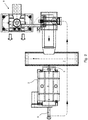
- Fig. 1 shows a schematic side view of an embodiment of a device according to the invention, by which the inventive method can be described.
- the exemplary embodiment chosen here involves the recycling of so-called PET bottles, which are preferably supplied to the device according to the invention in isolated form.
- the supply takes place at the in Fig. 1
- a forced feed with one or more screw conveyors could be provided, namely to promote the throughput.
- the forced feed for example, the so-called screw feed, in particular in the context of a rotor variant according to the Fig. 5 and 6 according to which it works particularly effectively on the basis of a forced loading.
- the device according to the invention works in an ideal manner dry, namely due to the design features realized here.
- the device shown comprises a housing 2 with a chamber therein.
- a rotor 3 is arranged, which is equipped with blades 4 or tools 11. Dirt present on the PET bottles or foreign bodies located thereon, for example labels, are literally knocked off by the blades 4 or tools 11.
- the PET bottles freed from the foreign bodies are transferred from the device or out of the housing 2 onto a conveyor belt 7 and from there fed to the further recycling process.
- the foreign bodies released from the PET bottles pass via the screw conveyor 6 into an independent separating device 8, which may comprise a zig-zag channel and a cyclone 10.
- an independent separating device 8 which may comprise a zig-zag channel and a cyclone 10.
- the remainder, ie the labels and the dirt or foreign bodies, are then displayed as shown in FIG Fig. 3 fed to a waste station 9, where also a separation can be completed.
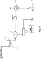
- Fig. 4a shows a schematic diagram of the sequence of the method according to the invention, wherein the parts to be recycled or PET bottles - isolated - the device according to the invention and thus the housing 2 are supplied.
- the rotor 3 is arranged with the blades 4, as shown in FIG Fig. 4a is indicated.
- Canceled labels, dirt, etc. preferably pass through the perforated plate 5 through a screw conveyor 6 to a further separating device 8, which can operate by gravity. Separate plastic parts can be recycled.
- the freed of the foreign bodies PET bottles are conveyed out of the housing 2 on the conveyor belt 7 and fed from there to the further recycling process.
- detached foreign bodies together with residual plastic parts pass through the screw conveyor 6 to the further separating device 8, from where the remaining plastic parts are also fed to the conveyor belt 7 and thus to the recycling process after further separation.
- the detached foreign bodies are fed in a conventional manner preferably via a cyclone 10 a waste station 9, where there is also a sorted separation possible but not mandatory.
- the device according to the invention can be embodied entirely without a sieve or perforated plate, according to which the fraction is carried out within a closed drum or within a closed housing 3 made of non-perforated sheet metal. After the device or the housing 2 would then take place a separation into good and bad fraction, namely there to divorce bottles and labels or dirt.
- a screening machine is arranged after the device instead of a converting air classification, which is sucked to deduct the so-called light fraction.
- a device may comprise a hood over the screening machine, wherein in the hood a suction connection is provided.
- this is also a kind of air classifier with automatic extraction.
- Fig. 4b shows a schematic diagram of a further variant of a possible sequence of the method according to the invention, where there are afflicted with dirt, labels or the like PET bottles of the device according to the invention, namely the housing 2, in which a rotor 3 is arranged with suitable tools 11 , The rotor 3 rotates relative to the housing 2. Basically is a relative movement between the rotor 3 and the housing 2 is required, no matter which component is actively rotating.
- housing 2 also called outer drum
- labels and caps are separated from the actual PET bottle, without destroying or knocking off the bottle head, after which a separation of cap and bottleneck would only be possible with considerable effort or not at all.
- the comminuted material passes from the device or the housing 2 into a separating device 8 to be understood as a separating step, which can operate, for example, by gravity.
- the rotor 3 arranged in the housing 2 it is essential that the rotor 3 be used in combination with its tools 11 (see FIG Fig. 5 . 6 and 7 ) and the outer drum or the housing 2 is able to remove labels and caps from the containers or PET bottles, without destroying the bottlenecks. This is of particular importance, especially as a destruction of the container necks would lead to a loss of material in the recycling process, namely because the bottlenecks would have to be separated with the caps.
- the outer drum or the housing 2 is rotationally fixed, wherein the rotor 3 rotates.
- a reverse kinematics is conceivable.
- the axes of housing 2 or outer drum and rotor 3 are arranged coaxially.
- An eccentric arrangement of the rotor 3 within the housing 2 is conceivable or may even be advantageous, namely to define within the housing 2 zones with different exposure intensity with respect to the bottles.
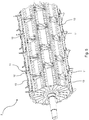
- Fig. 5 shows a schematic side view of an embodiment of a rotor 3, as it can be arranged in the housing 2 and in the outer drum formed by the housing 2.
- the rotor 3 is rectangular in cross-section, but can also - as needed - be round along the circumference.
- Fig. 5 clearly shows that the rotor 3 comprises fastening strips 13, which serve in pairs for attaching arranged on holding plates 12 tools 11.
- the tools 11 are arranged such that they define a twist and thus a conveying direction in a defined direction of rotation with respect to the material to be comminuted.
- the direction of rotation is to be understood in the clockwise direction.
- rotor 3 rotates with a relative movement to the housing 2, wherein the housing 2 and the outer drum formed by the housing 2 is non-rotatable.
- the axes of rotor 3 and housing 2 are arranged coaxially.
- Fig. 6 shows the item Fig. 5 in an end view, where there particularly well the angular configuration of the rotor 3 and the stepped design of the tools 11 can be seen. Also lets Fig. 6 clearly recognize that the tools 11 are mounted on retaining plates 12, which in turn sit on the fastening strips 13. The holding plates 12 are preferably screwed onto the fastening strips 13. An exchange of individual tools 11 and holding plates 12 is possible at any time.
- Fig. 7 shows in detail, enlarged, a holding plate 12 with tool 11 disposed thereon, wherein the tool 11 is arranged angled, resulting in the rotation direction of the rotor 3, the conveying direction of the material.
- the urging means may be rigidly or movably mounted on the rotor 3 in the tangential direction.
- the rotor 3 itself can be arranged in the housing 2 or in the drum centric or eccentric to the drum axis, wherein the drum or the housing 2 can be cylindrical or conical to the axis of rotation of the rotor 3.
- drum or the housing 2 is equipped on the inside with elements which influence the trajectory of the discontinued parts.
- the material input into the device, d. H. into the housing 2 is preferably arranged tangentially to the circumferential movement of the rotor 3 in the direction of the rotational movement of the rotor 3.
- the material discharge from the device or from the housing 2 is preferably aligned tangentially to the circumferential movement of the rotor 3 in the direction of the rotational movement of the rotor 3.
- the device according to the invention not only serves for the mere treatment of the parts, but also holds a further function, namely the dissolution of bales and briquettes and this combined with the actual function of the pre-cleaning.
Description
Die Erfindung betrifft ein Verfahren zur Vorreinigung von Teilen aus Kunststoff im Rahmen eines Recycling-Prozesses, wobei an den Teilen zu entfernende Fremdkörper anhaften, insbesondere zum Entfernen von Fremdkörpern an Teilen aus Kunststoff, vorzugsweise zum Entfernen von Etiketten, Verschmutzungen, etc. an gebrauchten Kunststoffflaschen, beispielsweise PET-Flaschen.
Des Weiteren betrifft die Erfindung eine Vorrichtung zur Anwendung des erfindungsgemäßen Verfahrens.The invention relates to a method for pre-cleaning parts made of plastic as part of a recycling process, wherein adhering to the parts foreign bodies adhere, in particular for removing foreign bodies on parts made of plastic, preferably for removing labels, dirt, etc. on used plastic bottles , for example PET bottles.
Furthermore, the invention relates to a device for applying the method according to the invention.
Vorrichtungen und Verfahren der eingangs genannte Art sind aus den Druckschriften
Aus der Praxis sind Anlagen und Verfahren zum Aufbereiten von Kunststoffabfällen (z.B. PET-Flaschen) bekannt. Dabei werden Verschmutzungen entfernt, wobei die Kunststoffabfälle regelmäßig einer Nasswäsche unterzogen werden.In practice, plants and processes for processing plastic waste (e.g., PET bottles) are known. This contamination is removed, the plastic waste is regularly subjected to wet scrubbing.
Oft ist sogar eine Heißwäsche erforderlich, und zwar unter Zugabe von Reinigungschemikalien, beispielsweise Natronlauge, NaOH, etc. Dabei wird das Waschmedium ständig regeneriert, was zu einem hohen Aufwand und zu erheblichen Umweltverschmutzungen führt, würde man das Waschmedium nach vollzogener Wäsche ins Abwasser geben.Often even a hot wash is required, with the addition of cleaning chemicals, such as sodium hydroxide, NaOH, etc. The washing medium is constantly regenerated, which leads to high costs and significant environmental pollution, you would enter the washing medium after completion of laundry in the wastewater.
Ein besonderes Problem sind Verunreinigungen bzw. Fremdkörper an Kunststoffflaschen, beispielsweise an sogenannten PET-Flaschen. Zum Recyceln der PET-Flaschen müssen die Etiketten - bestehend aus anderem Material wie die Flasche und meist bedruckt - entfernt werden. Sie bestehen oftmals aus PVC und sind in einer konventionellen Waschanlage schwer entfernbar. Oftmals haften an den PET-Flaschen zudem sonstige Fremdkörper wie Steine, Glas, kleine Metallstücke, etc., die von einem Überbandmagneten nicht erfasst werden. Auch diese Fremdkörper sind von dem zu recycelnden Kunststoff zu entfernen.A particular problem is contaminants or foreign bodies on plastic bottles, for example on so-called PET bottles. To recycle the PET bottles, the labels - made of other material such as the bottle and usually printed - must be removed. They are often made of PVC and are difficult to remove in a conventional car wash. Often adhere to the PET bottles also other foreign objects such as stones, glass, small pieces of metal, etc., which are not detected by an overband magnet. Also these foreign bodies are to be removed from the plastic to be recycled.
Des Weiteren ist von Bedeutung, dass es sich bei den an den PET-Flaschen haftenden Fremdkörpern oftmals um abrasive Bestandteile handelt. Werden diese vor dem Zerkleinern bzw. Zermahlen der PET-Flaschen nicht entfernt, bedeutet dies einen erheblichen Verschleiß an der Mühle. Des Weiteren sind Restinhalte aus den Flaschen zu entfernen, da nämlich das klebrige Zuckerwasser zu Störungen bei der Weiterverarbeitung bzw. beim Recycling führt. Außerdem wird durch Restflüssigkeit in den Flaschen die Abwasseraufbereitung belastet.Furthermore, it is important that the foreign bodies adhering to the PET bottles are often abrasive components. If these are not removed before crushing or crushing the PET bottles, this means a considerable wear on the mill. Furthermore, residual contents are to be removed from the bottles, since the sticky sugar water leads to disturbances during further processing or recycling. In addition, wastewater treatment is burdened by residual liquid in the bottles.
Der vorliegenden Erfindung liegt daher die Aufgabe zugrunde, ein Verfahren und eine Vorrichtung zur Vorreinigung von Teilen aus Kunststoff im Rahmen eines Recycling-Prozesses anzugeben, wodurch Kunststoffrecycling problemlos möglich ist. Die Kontamination des Wasserkreislaufs soll auf ein Minimum reduziert werden.The present invention is therefore based on the object of specifying a method and a device for pre-cleaning parts made of plastic in the context of a recycling process, whereby plastic recycling is easily possible. The contamination of the water cycle should be reduced to a minimum.
Erfindungsgemäß ist die voranstehende Aufgabe - in Bezug auf das Verfahren - durch die Merkmale des Patentanspruchs 1 gelöst. Danach ist das gattungsbildende Verfahren dadurch gekennzeichnet, dass die Fremdkörper durch mechanische Beanspruchung der Teile von diesen entfernt werden.According to the invention the above object - in relation to the method - solved by the features of claim 1. Thereafter, the generic method is characterized in that the foreign bodies are removed by mechanical stress on the parts of these.
In Bezug auf die erfindungsgemäße Vorrichtung ist die voranstehende Aufgabe durch die Merkmale des nebengeordneten Patentanspruchs 14 gelöst. Danach ist die gattungsbildende Vorrichtung gekennzeichnet durch ein Gehäuse mit einer Kammer zur Aufnahme der Teile, wobei in der Kammer Mittel zur mechanischen Beaufschlagung der Teile sowie Mittel zum Trennen der von den Teilen losgelösten Fremdkörper sowie zum Abführen der Fremdkörper und Teile auf separaten Pfaden vorgesehen sind.With regard to the device according to the invention, the above object is achieved by the features of the independent patent claim 14. Thereafter, the generic device is characterized by a housing having a chamber for receiving the parts, wherein in the chamber means for the mechanical loading of the parts and means for separating the foreign bodies detached from the parts and for discharging the foreign bodies and parts are provided on separate paths.
Erfindungsgemäß ist erkannt worden, dass es ohne Weiteres möglich ist, die an den zu recycelnden Kunststoffteilen anhaftenden Fremdkörper auf einfache Weise durch mechanische Beanspruchung der Teile von diesen zu entfernen. Erfolgt die Beanspruchung auf rein mechanische Weise, ist eine Vorwäsche mit Dampf, welche äußerst energieaufwendig ist, nicht erforderlich. Des Weiteren ist für das erfindungsgemäße Verfahren wesentlich, dass das Entfernen der Fremdkörper ohne vorherige Zerkleinerung der Teile bzw. PET-Flaschen erfolgt. Entsprechend wird die Mühle nicht durch abrasive Fremdkörper beansprucht. Ganz im Gegenteil werden nach dem erfindungsgemäßen Verfahren die aus Kunststoff bestehenden Teile - ohne vorgeschaltete Zerkleinerung - mechanisch derart beansprucht, dass sich die Fremdkörper, ganz gleich welcher Art, von den Kunststoffteilen lösen.According to the invention, it has been recognized that it is readily possible to easily remove the foreign bodies adhering to the plastic parts to be recycled by mechanical stress on the parts thereof. If the stress is in a purely mechanical manner, a pre-wash with steam, which is extremely energy-intensive, is not required. Furthermore, it is essential for the method according to the invention that the removal of the foreign bodies takes place without prior comminution of the parts or PET bottles. Accordingly, the mill is not stressed by abrasive foreign bodies. On the contrary, according to the inventive method, the parts made of plastic - without upstream comminution - mechanically claimed so that the foreign body, no matter what kind, solve the plastic parts.
Durch die Bewegung der Kunststoffteile innerhalb der Vorrichtung kommt es zu einer Friktionsbildung (Reibung) der Kunststoffteile aneinander und an den Maschinenteilen, welche ebenfalls ein Ablösen von Verschmutzungen bewirkt, zumindest aber begünstigt.Due to the movement of the plastic parts within the device, a frictional formation (friction) of the plastic parts against each other and on the machine parts, which also causes a detachment of dirt, but at least favors.
In besonders vorteilhafter Weise werden die Fremdkörper ausschließlich mechanisch von den Teilen bzw. PET-Flaschen entfernt. Die mechanische Beanspruchung kann eine Deformation der Teile bedeuten, so dass sich die Fremdkörper aufgrund der Deformation der Teile von diesen lösen. Im Konkreten ist es denkbar, dass die Teile durch Biegen, Stauchen und/oder Dehnen deformiert werden, wodurch ein Lösen der Fremdkörper von den Teilen erfolgt.In a particularly advantageous manner, the foreign bodies are removed only mechanically from the parts or PET bottles. The mechanical stress may mean a deformation of the parts, so that the foreign body due to the deformation of the parts of these solve. Concretely, it is conceivable that the parts are deformed by bending, upsetting and / or stretching, whereby the foreign bodies are released from the parts.
Grundsätzlich ist es auch möglich, dass die Fremdkörper unter zusätzlicher Einwirkung einer Flüssigkeit oder von Dampf von den Teilen entfernt werden, wobei auf jeden Fall eine mechanische Einwirkung auf die Teile stattfindet. Auch ist es denkbar, dass das Entfernen der Fremdkörper unter zusätzlicher Einwirkung von Wärme oder Kälte erfolgt, um nämlich das Lösen der Fremdkörper von den Teilen zu begünstigen.In principle, it is also possible for the foreign bodies to be removed from the parts with the additional action of a liquid or of steam, in which case a mechanical action on the parts takes place in any case. It is also conceivable that the removal of the foreign body takes place under additional action of heat or cold, namely to promote the dissolution of the foreign body of the parts.
In ganz besonders vorteilhafter Weise werden die Fremdkörper von den Teilen bzw. PET-Flaschen regelrecht abgeschlagen. Dabei kann eine Zerkleinerung der Fremdkörper stattfinden, was das Trennen der Fremdkörper von den zu recycelnden Teilen begünstigt.In a particularly advantageous manner, the foreign body from the parts or PET bottles are literally knocked off. In this case, a comminution of the foreign body take place, which favors the separation of the foreign body from the parts to be recycled.
Sollten sich in den zu recycelnden Flaschen noch irgendwelche Restbestände an Flüssigkeit befinden, wäre es von Vorteil, die Flüssigkeit aus den Flaschen auslaufen zu lassen. Dazu könnten die Teile bzw. Flaschen im Rahmen der mechanischen Beanspruchung zumindest geringfügig angeritzt oder angeschnitten, jedoch nicht zerkleinert werden. Das Anritzen der Teile hat den Vorteil, dass beliebige Flüssigkeit nach außerhalb gelangt, ohne dass die Gefahr einer vorzeitigen Zerkleinerung der PET-Flaschen droht, wodurch eine Trennung zwischen dem PET-Material und den Fremdkörpern erschwert wäre.If there are any residual liquid left in the bottles to be recycled, it would be an advantage to drain the liquid from the bottles. For this purpose, the parts or bottles could be at least slightly scratched or cut in the context of mechanical stress, but not crushed. The scoring of the parts has the advantage that any liquid gets outside without the risk of premature crushing of the PET bottles threatens, whereby a separation between the PET material and the foreign bodies would be difficult.
Die zu recycelnden Teile bzw. Flaschen werden nach dem Sammeln üblicherweise zu Ballen verdichtet und entsprechend zusammengepresst. In dieser Form wird das zu recycelnde Material dem Recycling-Prozess zugeführt. Zur erfindungsgemäßen Vorreinigung wird der Ballen aufgelöst bzw. werden die Teile vereinzelt und in vereinzelter Form dem Vorreinigungsprozess zugeführt. Entsprechend erfolgt die Entfernung der Fremdkörper nach einer Auflösung des Ballens bzw. nach einer Vereinzelung der Teile, wodurch der Vorreinigungsprozess ganz erheblich begünstigt ist.The parts or bottles to be recycled are usually compacted after collection into bales and pressed together accordingly. In this form, the material to be recycled is sent to the recycling process. For pre-cleaning according to the invention, the bale is dissolved or the parts are separated and fed in isolated form to the pre-cleaning process. Accordingly, the removal of the foreign body is carried out after a dissolution of the bale or after a separation of the parts, whereby the pre-cleaning process is promoted quite considerably.
Des Weiteren ist es von ganz besonderem Vorteil, wenn die Entfernung der Fremdkörper über eine vorgebbare Verweilzeit und/oder eine vorgebbare Beanspruchungsintensität erfolgt. Beide Parameter sind einstellbar und lassen sich - möglichst in Abhängigkeit voneinander und in Abhängigkeit vom Material bzw. vom Verschmutzungsgrad - einstellen und optimieren.Furthermore, it is of very particular advantage if the removal of the foreign bodies takes place over a predefinable residence time and / or a predefinable stress intensity. Both parameters are adjustable and can be adjusted and optimized as far as possible depending on each other and depending on the material or the degree of contamination.
Grundsätzlich ist es nicht auszuschließen, dass während des Vorreinigungsprozesses kleine Teile der PET-Flaschen von diesen abgetrennt und gemeinsam mit den Fremdkörpern separiert werden, wenngleich ausschließlich die Fremdkörper zu separieren sind. Insoweit ist es von Vorteil, wenn die von den Teilen gelösten und separierten Fremdkörper nebst Kunststoffteile einem abermaligen Trennprozess zugeführt werden, wonach Rest-Kunststoffteile der PET-Flaschen abermals getrennt und dem Recycling-Prozess zugeführt werden. Der tatsächliche Schmutz, d.h. die von den Flaschen gelösten Fremdkörper, beispielsweise Etiketten, Metall, etc., werden dann entsorgt oder einem weiteren Recycling-Prozess zugeführt.In principle, it can not be ruled out that during the pre-cleaning process small parts of the PET bottles are separated from these and separated together with the foreign bodies, although only the foreign bodies are to be separated. In that regard, it is advantageous if the dissolved and separated from the parts foreign body are supplied in addition to plastic parts a repeated separation process, after which residual plastic parts of the PET bottles are again separated and fed to the recycling process. The actual dirt, i. the foreign bodies dissolved by the bottles, for example labels, metal, etc., are then disposed of or sent to a further recycling process.
An dieser Stelle sei angemerkt, dass dem erfindungsgemäßen Verfahren der eigentliche Recycling-Prozess folgt, wobei die von Fremdkörpern befreiten Teile bzw. Flaschen vorzugsweise über eine Fördereinrichtung dem weiteren Recycling-Prozess zugeführt werden, der dann in einer für sich bekannten Weise vollzogen wird.It should be noted at this point that the process according to the invention is followed by the actual recycling process, wherein the parts or bottles freed from foreign bodies are preferably fed to the further recycling process via a conveyor, which is then carried out in a manner known per se.
Die erfindungsgemäße Vorrichtung umfasst ein Gehäuse mit einer Kammer zur Aufnahme der Teile bzw. PET-Flaschen, wobei in der Kammer Mittel zur mechanischen Beaufschlagung der Teile sowie Mittel zum Trennen der von den Teilen losgelösten Fremdkörper sowie zum Abführen der Fremdkörper und der Teile auf separaten Pfaden vorgesehen sind.The device according to the invention comprises a housing with a chamber for accommodating the parts or PET bottles, wherein in the chamber means for mechanical loading of the parts and means for separating the foreign body detached from the parts and for discharging the foreign body and the parts on separate paths are provided.
Mit anderen Worten werden die mechanisch gelösten Fremdkörper beispielsweise über ein Lochblech mit im Durchmesser geeignet definierten Löchern einer Fördereinrichtung zugeführt, möglichst unterhalb des Gehäuses bzw. der Kammer. Die Fremdkörper könnten dort über eine Förderschnecke in eine abermalige Trenneinrichtung gelangen, beispielsweise in einen Zyklon. Dort erfolgt eine abermalige Trennung der Fremdkörper von Rest-Kunststoffteilen, die dann wieder dem Recycling-Prozess zugeführt werden.In other words, the mechanically dissolved foreign bodies are fed, for example, via a perforated plate with holes of suitable diameter, to a conveying device, possibly below the housing or the chamber. The foreign bodies could get there via a screw conveyor in a repeated separation device, for example in a cyclone. There is a repeated separation of the foreign body of residual plastic parts, which are then returned to the recycling process.
Die zur Vorreinigung dienende Kammer könnte als Zentrifugaleinrichtung oder Trommel ausgeführt sein. In dem Gehäuse bzw. in der Kammer ist ein Rotor mit Beaufschlagungsmitteln vorgesehen. Grundsätzlich ist es von Vorteil, wenn der innen angeordnete Rotor gegenüber dem Gehäuse dreht. Eine umgekehrte Funktion ist denkbar.The pre-cleaning chamber could be designed as a centrifugal device or a drum. In the housing or in the chamber, a rotor is provided with loading means. In principle, it is advantageous if the internally arranged rotor rotates relative to the housing. A reverse function is conceivable.
Die Beaufschlagungsmittel können unterschiedlich ausgebildet sein, beispielsweise als Stäbe, Flügel, Paddel oder dgl. Auch ist es denkbar, dass die Beaufschlagungsmittel Messer umfassen, wobei die Stäbe, Flügel, Paddel oder dgl. zumindest teilweise mit Messern bestückt sein können, die zum Anritzen der Kunststoffteile bzw. der PET-Flaschen dienen. An dieser Stelle sein angemerkt, dass es von ganz besonderem Vorteil ist, wenn im Rahmen der Vorreinigung keine Zerkleinerung der Teile bzw. PET-Flaschen stattfindet. Entsprechend sind die Messer derart auszulegen, dass die Flaschen allenfalls angeritzt, nicht jedoch zerschnitten werden.The loading means may be formed differently, for example as rods, wings, paddles or the like. It is also conceivable that the loading means comprise knives, wherein the rods, wings, paddles or the like. At least partially can be equipped with knives for scoring the Plastic parts or PET bottles serve. It should be noted at this point that it is particularly advantageous if there is no comminution of the parts or PET bottles during the pre-cleaning. Accordingly, the blades are designed in such a way that the bottles are at best scratched, but not cut.
Es gibt nun verschiedene Möglichkeiten, die Lehre der vorliegenden Erfindung in vorteilhafter Weise auszugestalten und weiterzubilden. Dazu ist auf die nachfolgende Erläuterung eines bevorzugten Ausführungsbeispiels der Erfindung anhand der Zeichnung zu verweisen. In Verbindung mit der Erläuterung des bevorzugten Ausführungsbeispiels der Erfindung anhand der Zeichnung werden auch im Allgemeinen bevorzugte Ausgestaltungen und Weiterbildungen der Lehre erläutert. In der Zeichnung zeigen
- Fig. 1
- in einer schematischen Seitenansicht ein Ausführungsbeispiel einer erfindungsgemäßen Vorrichtung,
- Fig. 2
- in einer schematischen Draufsicht den Gegenstand aus
Fig. 1 , - Fig. 3
- in einer schematischen Seitenansicht die Trennung etwaiger Rest-Kunststoffteile von den Fremdkörpern und
- Fig. 4a
- in einem schematischem Diagramm den Ablauf des erfindungsgemäßen Verfahrens im Rahmen einer ersten Variante,
- Fig. 4b
- in einem schematischen Diagramm den Ablauf des erfindungsgemäßen Verfahrens im Rahmen einer zweiten Variante,
- Fig. 5
- in einer schematischen Seitenansicht ein Ausführungsbeispiel eines mit Werkzeugen bestückten Rotors,
- Fig. 6
- in einer schematischen Stirnansicht den Gegenstand aus
Fig. 5 und - Fig. 7
- in einer schematischen Ansicht, gegenüber den
Fig. 5 und6 vergrößert, ein auf einer Halteplatte angeordnetes Werkzeug des Rotors.
- Fig. 1
- in a schematic side view of an embodiment of a device according to the invention,
- Fig. 2
- in a schematic plan view of the subject
Fig. 1 . - Fig. 3
- in a schematic side view, the separation of any residual plastic parts from the foreign bodies and
- Fig. 4a
- 2 shows a schematic diagram of the sequence of the method according to the invention within the scope of a first variant,
- Fig. 4b
- 2 shows a schematic diagram of the sequence of the method according to the invention in the context of a second variant,
- Fig. 5
- in a schematic side view of an embodiment of a tooled rotor,
- Fig. 6
- in a schematic end view of the subject matter
Fig. 5 and - Fig. 7
- in a schematic view, opposite to the
Fig. 5 and6 enlarged, arranged on a holding plate tool of the rotor.
Bei dem hier gewählten Ausführungsbeispiel geht es um das Recyceln sogenannter PET-Flaschen, die der erfindungsgemäßen Vorrichtung vorzugsweise vereinzelt zugeführt werden. Die Zuführung erfolgt bei dem in
Es sei angemerkt, dass die erfindungsgemäße Vorrichtung in idealer Weise trocken arbeitet, nämlich aufgrund der hier realisierten konstruktiven Merkmale.It should be noted that the device according to the invention works in an ideal manner dry, namely due to the design features realized here.
Die in
Über ein Lochblech 5 gelangen die abgeschlagenen Fremdkörper auf bzw. in einen Schraubenförderer 6 und werden von dort einer weiteren Separierung zugeführt.About a
Die von den Fremdkörpern befreiten PET-Flaschen werden von der Vorrichtung bzw. aus dem Gehäuse 2 heraus auf ein Förderband 7 verbracht und von dort aus dem weiteren Recycling-Prozess zugeführt.The PET bottles freed from the foreign bodies are transferred from the device or out of the
Die von den PET-Flaschen gelösten Fremdkörper gelangen über den Schraubenförderer 6 in eine davon unabhängige Trenneinrichtung 8, die einen Zick-Zack-Kanal und einen Zyklon 10 umfassen kann. Dort werden Rest-Kunststoffteile, die von den PET-Flaschen unbeabsichtigt abgeschlagen worden sind, von dem Fremdkörpern getrennt und dem Förderband 7 zugeführt, so dass auch diese Teile zum Recyceln zur Verfügung stehen. Der Rest, d.h. die Etiketten und der Schmutz bzw. die Fremdkörper, werden dann entsprechend der Darstellung in
Abgeschlagene Etiketten, Schmutz, etc. gelangen vorzugsweise durch das Lochblech 5 hindurch über einen Schraubenförderer 6 zu einer weiteren Trenneinrichtung 8, die über Schwerkraft arbeiten kann. Davon getrennte Kunststoffteile lassen sich dem Recycling-Prozess zuführen.Canceled labels, dirt, etc. preferably pass through the
Die von den Fremdkörpern befreiten PET-Flaschen werden aus dem Gehäuse 2 heraus auf das Förderband 7 gefördert und von dort aus dem weiteren Recycling-Prozess zugeführt. Wie bereits zuvor erwähnt, gelangen losgelöste Fremdkörper nebst Rest-Kunststoffteile über den Schraubenförderer 6 zu der weiteren Trenneinrichtung 8, wobei von dort aus die Rest-Kunststoffteile nach weiterer Trennung ebenfalls dem Förderband 7 und somit dem Recycling-Prozess zugeführt werden.The freed of the foreign bodies PET bottles are conveyed out of the
Die losgelösten Fremdkörper werden in konventioneller Weise vorzugsweise über einen Zyklon 10 einer Abfallstation 9 zugeführt, wobei dort ebenfalls eine sortenreine Trennung möglich aber nicht zwingend erforderlich ist.The detached foreign bodies are fed in a conventional manner preferably via a cyclone 10 a
An dieser Stelle sei angemerkt, dass die erfindungsgemäße Vorrichtung ganz ohne Sieb bzw. Lochblech ausgeführt sein kann, wonach nämlich die Fraktion innerhalb einer geschlossenen Trommel bzw. innerhalb eines geschlossenen Gehäuses 3 aus ungelochtem Blech durchgeführt wird. Nach dem Gerät bzw. dem Gehäuse 2 würde dann eine Trennung in Gut- und Schlechtfraktion stattfinden, um dort nämlich Flaschen und Etiketten bzw. Schmutz zu scheiden.It should be noted at this point that the device according to the invention can be embodied entirely without a sieve or perforated plate, according to which the fraction is carried out within a closed drum or within a
Auch ist es denkbar, dass nach der Vorrichtung anstelle einer konvertierenden Windsichtung eine Siebmaschine angeordnet ist, die zum Abzug der sogenannten Leichtfraktion besaugt wird. Eine solche Einrichtung kann eine Haube über der Siebmaschine umfassen, wobei in der Haube ein Absauganschluss vorgesehen ist. Letztendlich handelt es sich auch hier um eine Art Windsichter mit automatischer Absaugung.It is also conceivable that a screening machine is arranged after the device instead of a converting air classification, which is sucked to deduct the so-called light fraction. Such a device may comprise a hood over the screening machine, wherein in the hood a suction connection is provided. Ultimately, this is also a kind of air classifier with automatic extraction.
Innerhalb des Gehäuses 2, auch Außentrommel genannt, werden Etiketten und Verschlusskappen von der eigentlichen PET-Flasche getrennt, ohne den Flaschenkopf zu zerstören bzw. abzuschlagen, wonach eine Separierung von Verschlusskappe und Flaschenhals nur noch mit erheblichem Aufwand oder gar nicht möglich wäre.Within the
Jedenfalls gelangt das Zerkleinerungsgut von der Vorrichtung bzw. dem Gehäuse 2 in eine als Separierungsstufe zu verstehende Trenneinrichtung 8, die beispielsweise über Schwerkraft arbeiten kann.In any case, the comminuted material passes from the device or the
In Bezug auf den im Gehäuse 2 angeordneten Rotor 3 ist wesentlich, dass der Rotor 3 in Kombination mit seinen Werkzeugen 11 (siehe
Bevorzugt ist die Außentrommel bzw. das Gehäuse 2 drehfest, wobei der Rotor 3 dreht. Eine umgekehrte Kinematik ist denkbar. Regelmäßig sind die Achsen von Gehäuse 2 bzw. Außentrommel und Rotor 3 koaxial angeordnet. Eine exzentrische Anordnung des Rotors 3 innerhalb des Gehäuses 2 ist denkbar bzw. kann sogar von Vorteil sein, um nämlich innerhalb des Gehäuses 2 Zonen mit unterschiedlicher Einwirkungsintensität in Bezug auf die Flaschen zu definieren.Preferably, the outer drum or the
Die in
Der in
Die im Gehäuse 2 bzw. am Rotor 3 vorgesehenen Beaufschlagungsmittel - Werkzeuge 4,11 - können am Rotor 3 fest angebracht oder dort in der Position und im Winkel verstellbar sein, um auf die Verweilzeit der zu behandelnden Teile in der Vorrichtung Einfluss nehmen zu können. Im Konkreten können die Beaufschlagungsmittel in tangentialer Richtung starr oder beweglich am Rotor 3 befestigt sein. Der Rotor 3 selbst kann in dem Gehäuse 2 bzw. in der Trommel zentrisch oder exzentrisch zur Trommelachse angeordnet sein, wobei die Trommel bzw. das Gehäuse 2 zylindrisch oder konisch zur Drehachse des Rotors 3 ausgebildet sein kann.The loading means provided in the
Ebenso ist es denkbar, dass die Trommel oder das Gehäuse 2 auf der Innenseite mit Elementen bestückt ist, welche die Flugbahn der aufgegebenen Teile beeinflussen.It is also conceivable that the drum or the
Der Materialeintrag in die Vorrichtung, d. h. in das Gehäuse 2 hinein, ist vorzugsweise tangential zur Umfangbewegung des Rotors 3 in Richtung der Drehbewegung des Rotors 3 angeordnet.The material input into the device, d. H. into the
Der Materialaustrag aus der Vorrichtung bzw. aus dem Gehäuse 2 ist vorzugsweise tangential zur Umfangsbewegung des Rotors 3 in Richtung der Drehbewegung des Rotors 3 ausgerichtet.The material discharge from the device or from the
Des Weiteren sei angemerkt, dass die erfindungsgemäße Vorrichtung nicht nur zur bloßen Behandlung der Teile dient, vielmehr eine weitere Funktion innehat, nämlich das Auflösen von Ballen und Briketts und diese mit der eigentlichen Funktion der Vorreinigung vereint.Furthermore, it should be noted that the device according to the invention not only serves for the mere treatment of the parts, but also holds a further function, namely the dissolution of bales and briquettes and this combined with the actual function of the pre-cleaning.
Hinsichtlich weiterer vorteilhafter Ausgestaltungen der erfindungsgemäßen Lehre wird zur Vermeidung von Wiederholungen auf den allgemeinen Teil der Beschreibung sowie auf die beigefügten Patentansprüche verwiesen.With regard to further advantageous embodiments of the teaching of the invention, reference is made to avoid repetition to the general part of the specification and to the appended claims.
Schließlich sei ausdrücklich darauf hingewiesen, dass das voranstehend beschriebene Ausführungsbeispiel der erfindungsgemäßen Lehre lediglich zur Erörterung der beanspruchten Lehre dient, diese jedoch nicht auf das Ausführungsbeispiel einschränkt.Finally, it should be expressly understood that the above-described embodiment of the teaching of the invention is merely for the purpose of discussion of the claimed teaching, but does not limit this to the embodiment.
- 11
- Zuführschachtfeed chute
- 22
- Gehäuse, AußentrommelHousing, external drum
- 33
- Rotorrotor
- 44
- Schaufelshovel
- 55
- Lochblechperforated sheet
- 66
- Schraubenfördererscrew conveyor
- 77
- Förderbandconveyor belt
- 88th
- Trenneinrichtung, SeparationsstufeSeparator, separation stage
- 99
- Abfallstationwaste station
- 1010
- Zykloncyclone
- 1111
- WerkzeugTool
- 1212
- Halteplatte für das WerkzeugHolding plate for the tool
- 1313
- Befestigungsleistemounting strip
Claims (15)
- Method for pre-cleaning used plastics bottles in the context of a recycling process, wherein foreign bodies which are intended to be removed adhere to the plastics bottles, preferably for removing labels and/or contamination on the used plastics bottles,
wherein the foreign bodies are removed from the plastics bottles by means of mechanical loading of the plastics bottles in a housing (2) with a rotor (3) arranged therein, wherein the housing (2) and rotor (3) rotate relative to each other,
characterised in that, as a result of the rotor (3) which comprises stepped tools (11) in combination with the housing (2), labels and closure caps are removed from the plastics bottles, wherein the tools (11) are mounted on retention plates (12) which in turn rest on securing bars (13). - Method according to claim 1, characterised in that the foreign bodies are exclusively mechanically removed from the components.
- Method according to claim 1 or 2, characterised in that the foreign bodies are removed from the components by means of deformation of the components, in particular by means of bending, compression and/or expansion of the components.
- Method according to claim 1 and where applicable according to claim 3, characterised in that the foreign bodies are removed from the components with the additional action of a fluid.
- Method according to claim 1 and where applicable according to claim 3 or 4, characterised in that the foreign bodies are removed from the components with the additional action of heat or cold.
- Method according to any one of claims 1 to 5, characterised in that the foreign bodies are knocked off the components.
- Method according to any one of claims 1 to 6, characterised in that the components, in particular containers or bottles, are at least slightly slit or cut in the context of the mechanical loading.
- Method according to any one of claims 1 to 7, characterised in that the components are provided in a state compressed into balls and in that the removal of the foreign bodies is carried out after a separation of the ball or after a separation of the components.
- Method according to any one of claims 1 to 8, characterised in that the removal of the foreign bodies is carried out over a predeterminable dwell time and/or a predeterminable stress intensity.
- Method according to any one of claims 1 to 9, characterised in that the foreign bodies which are removed from the components are separated, where applicable with small plastics material components,
wherein the foreign bodies which are released and separated from the components can be supplied to a repeated separation operation in order to separate different materials, where applicable small plastics material components, and wherein where applicable the plastics material components are supplied to the recycling process at the appropriate location. - Device for pre-cleaning used plastics bottles in the context of a recycling process, wherein foreign bodies which are intended to be removed adhere to the used plastics bottles, preferably for removing labels and/or contamination on the used plastics bottles,
comprising a housing (2) having a chamber for receiving the components, wherein there are provided in the chamber a rotor (3) with tools (11) for mechanically acting on the components, and means for separating the foreign bodies which have been released from the components and for discharging the foreign bodies and components on separate paths, wherein the housing (2) and rotor (3) rotate relative to each other, characterised in that the tools (11) are constructed in a stepped manner and are mounted on retention plates (12) and in that the retention plates (12) rest on securing bars (13). - Device according to claim 11, characterised in that the housing (2) is constructed with the chamber which is constructed therein as a centrifugal device.
- Device according to claim 11 or 12, characterised in that the housing (2) is constructed with the chamber as a drum.
- Device according to any one of claims 11 to 13, characterised in that the rotor (3) has action means,
wherein
the action means may be constructed as rods, wings, paddles or the like. - Device according to claim 14, characterised in that the action means comprise blades and/or
in that the rods, wings, paddles or the like are at least partially provided with blades.
Priority Applications (1)
| Application Number | Priority Date | Filing Date | Title |
|---|---|---|---|
| PL14182316T PL2818255T3 (en) | 2009-07-27 | 2010-07-26 | Method and device for pre-cleaning parts made of plastic |
Applications Claiming Priority (2)
| Application Number | Priority Date | Filing Date | Title |
|---|---|---|---|
| DE102009034899 | 2009-07-27 | ||
| EP10754664.0A EP2459326B2 (en) | 2009-07-27 | 2010-07-26 | Apparatus for precleaning plastic parts |
Related Parent Applications (2)
| Application Number | Title | Priority Date | Filing Date |
|---|---|---|---|
| EP10754664.0A Division EP2459326B2 (en) | 2009-07-27 | 2010-07-26 | Apparatus for precleaning plastic parts |
| EP10754664.0A Division-Into EP2459326B2 (en) | 2009-07-27 | 2010-07-26 | Apparatus for precleaning plastic parts |
Publications (2)
| Publication Number | Publication Date |
|---|---|
| EP2818255A1 EP2818255A1 (en) | 2014-12-31 |
| EP2818255B1 true EP2818255B1 (en) | 2016-12-07 |
Family
ID=43064548
Family Applications (2)
| Application Number | Title | Priority Date | Filing Date |
|---|---|---|---|
| EP10754664.0A Active EP2459326B2 (en) | 2009-07-27 | 2010-07-26 | Apparatus for precleaning plastic parts |
| EP14182316.1A Active EP2818255B1 (en) | 2009-07-27 | 2010-07-26 | Method and device for pre-cleaning parts made of plastic |
Family Applications Before (1)
| Application Number | Title | Priority Date | Filing Date |
|---|---|---|---|
| EP10754664.0A Active EP2459326B2 (en) | 2009-07-27 | 2010-07-26 | Apparatus for precleaning plastic parts |
Country Status (6)
| Country | Link |
|---|---|
| US (2) | US9089878B2 (en) |
| EP (2) | EP2459326B2 (en) |
| DE (1) | DE102010032260A1 (en) |
| HU (1) | HUE025906T2 (en) |
| PL (2) | PL2459326T5 (en) |
| WO (1) | WO2011012113A1 (en) |
Families Citing this family (7)
| Publication number | Priority date | Publication date | Assignee | Title |
|---|---|---|---|---|
| ITMI20130615A1 (en) * | 2013-04-15 | 2014-10-16 | Previero Sas | METHOD AND EQUIPMENT FOR DRY REMOVAL OF LABELS FROM PLASTIC CONTAINERS |
| ITMI20130849A1 (en) * | 2013-05-24 | 2014-11-25 | Previero Sas | PLANT AND METHOD FOR SEPARATION OF LABELS AND OTHER MATERIALS FROM PLASTIC BOTTLES |
| EP3028941B1 (en) * | 2014-12-03 | 2019-07-10 | AIRBUS HELICOPTERS DEUTSCHLAND GmbH | A drainage end cap device for draining fluid from a hollow space in a vehicle |
| DE102015007912A1 (en) | 2015-06-20 | 2016-12-22 | Heinrich Buzga | Apparatus and method for treating in particular kleinstückigem bulk material |
| DE102017223027A1 (en) | 2017-12-18 | 2019-06-19 | Krones Ag | Device and method for unlabeling |
| JP7450251B2 (en) | 2020-04-16 | 2024-03-15 | 株式会社山本製作所 | label peeling machine |
| AU2021278379A1 (en) * | 2020-05-29 | 2023-01-05 | The University Of Sydney | A process for recycling a laminate and a solution therefor |
Citations (8)
| Publication number | Priority date | Publication date | Assignee | Title |
|---|---|---|---|---|
| US4599131A (en) | 1985-06-10 | 1986-07-08 | Owens-Illinois, Inc. | Delabeler for plastic containers |
| JP2002316104A (en) | 2001-02-19 | 2002-10-29 | Hitachi Zosen Corp | Dry cleaning method for plastic and apparatus therefor |
| DE10308500A1 (en) | 2003-02-26 | 2004-09-23 | Der Grüne Punkt - Duales System Deutschland Ag | Dry, damage-free removal of labels from hollow plastic products, particularly containers, involves passing containers between a drum and stator where various forces are applied for complete label removal |
| JP2005125139A (en) | 2003-10-21 | 2005-05-19 | Earth Technica:Kk | Dry washing apparatus for plastic waste material |
| TWM283694U (en) | 2005-09-05 | 2005-12-21 | Chiung-Yau Huang | Tag stripping machine for the recovery of plastic bottle |
| CN1962223A (en) | 2006-11-16 | 2007-05-16 | 浙江宝绿特环保技术有限公司 | Brand peeling apparatus |
| CN201020820Y (en) | 2006-11-16 | 2008-02-13 | 浙江宝绿特环保技术有限公司 | Tag-stripping machine |
| WO2009033587A1 (en) | 2007-09-13 | 2009-03-19 | Previero N. S.R.L. | Method and system for removing and separating labels, caps and contaminants in general from bottles and containers of plastic material |
Family Cites Families (6)
| Publication number | Priority date | Publication date | Assignee | Title |
|---|---|---|---|---|
| US5289978A (en) * | 1991-07-08 | 1994-03-01 | Lundquist Lynn C | Apparatus for continuous container label removal |
| DE69822228T2 (en) * | 1998-04-29 | 2004-07-29 | Amut S.P.A. | DEVICE FOR TREATING REUSABLE PLASTIC MATERIALS |
| JP2002316101A (en) † | 2001-02-19 | 2002-10-29 | Hitachi Zosen Corp | Dry cleaning apparatus for plastic |
| CA2359166C (en) * | 2001-10-16 | 2008-07-08 | Merlin Plastics Alberta Inc. | Label release and separation system |
| JP2006182393A (en) * | 2004-12-27 | 2006-07-13 | Nankai Kogyo Kk | Label removing device for bottle made of resin |
| ATE491534T1 (en) * | 2007-10-18 | 2011-01-15 | Amut Spa | APPARATUS AND METHOD FOR CONTINUOUSLY WASHING PLASTIC CONTAINERS AND REMOVAL IMPURITIES AND LABELS FROM THEIR SURFACE |
-
2010
- 2010-07-26 PL PL10754664T patent/PL2459326T5/en unknown
- 2010-07-26 WO PCT/DE2010/000872 patent/WO2011012113A1/en active Application Filing
- 2010-07-26 PL PL14182316T patent/PL2818255T3/en unknown
- 2010-07-26 HU HUE10754664A patent/HUE025906T2/en unknown
- 2010-07-26 US US13/144,849 patent/US9089878B2/en active Active
- 2010-07-26 EP EP10754664.0A patent/EP2459326B2/en active Active
- 2010-07-26 EP EP14182316.1A patent/EP2818255B1/en active Active
- 2010-07-26 DE DE102010032260A patent/DE102010032260A1/en not_active Ceased
-
2014
- 2014-09-08 US US14/480,205 patent/US20150052697A1/en not_active Abandoned
Patent Citations (8)
| Publication number | Priority date | Publication date | Assignee | Title |
|---|---|---|---|---|
| US4599131A (en) | 1985-06-10 | 1986-07-08 | Owens-Illinois, Inc. | Delabeler for plastic containers |
| JP2002316104A (en) | 2001-02-19 | 2002-10-29 | Hitachi Zosen Corp | Dry cleaning method for plastic and apparatus therefor |
| DE10308500A1 (en) | 2003-02-26 | 2004-09-23 | Der Grüne Punkt - Duales System Deutschland Ag | Dry, damage-free removal of labels from hollow plastic products, particularly containers, involves passing containers between a drum and stator where various forces are applied for complete label removal |
| JP2005125139A (en) | 2003-10-21 | 2005-05-19 | Earth Technica:Kk | Dry washing apparatus for plastic waste material |
| TWM283694U (en) | 2005-09-05 | 2005-12-21 | Chiung-Yau Huang | Tag stripping machine for the recovery of plastic bottle |
| CN1962223A (en) | 2006-11-16 | 2007-05-16 | 浙江宝绿特环保技术有限公司 | Brand peeling apparatus |
| CN201020820Y (en) | 2006-11-16 | 2008-02-13 | 浙江宝绿特环保技术有限公司 | Tag-stripping machine |
| WO2009033587A1 (en) | 2007-09-13 | 2009-03-19 | Previero N. S.R.L. | Method and system for removing and separating labels, caps and contaminants in general from bottles and containers of plastic material |
Also Published As
| Publication number | Publication date |
|---|---|
| US9089878B2 (en) | 2015-07-28 |
| PL2818255T3 (en) | 2017-06-30 |
| HUE025906T2 (en) | 2016-04-28 |
| EP2459326A1 (en) | 2012-06-06 |
| DE102010032260A1 (en) | 2011-02-10 |
| WO2011012113A1 (en) | 2011-02-03 |
| EP2818255A1 (en) | 2014-12-31 |
| EP2459326B1 (en) | 2015-09-09 |
| US20110271982A1 (en) | 2011-11-10 |
| US20150052697A1 (en) | 2015-02-26 |
| EP2459326B2 (en) | 2021-10-06 |
| PL2459326T3 (en) | 2016-02-29 |
| PL2459326T5 (en) | 2022-02-07 |
Similar Documents
| Publication | Publication Date | Title |
|---|---|---|
| EP2818255B1 (en) | Method and device for pre-cleaning parts made of plastic | |
| EP0394233B1 (en) | Device for preparation of materials | |
| EP2052791B1 (en) | Device and method for cleaning bulk material | |
| EP2945788B1 (en) | Device and method for removing impurities from shredded plastic | |
| EP2705939B1 (en) | Method and apparatus for the reprocessing of labelled plastic items | |
| EP3024973B1 (en) | Device and method for processing composite materials containing fibers | |
| EP1673206B1 (en) | Pet bottle recycling | |
| WO1997031716A1 (en) | Process and facility for treating and sorting recyclable waste materials | |
| EP2456560B1 (en) | Method and device for preparing broken glass | |
| DE10308500A1 (en) | Dry, damage-free removal of labels from hollow plastic products, particularly containers, involves passing containers between a drum and stator where various forces are applied for complete label removal | |
| DE3844263C1 (en) | ||
| EP1890798A1 (en) | Waste glass label remover | |
| DE102014220330B4 (en) | Process for the preparation of plastics and apparatus | |
| DE3907445C2 (en) | ||
| EP3532205A1 (en) | Impact reactor for comminuting composite material, and method for comminuting composite material | |
| DE3731634C2 (en) | ||
| EP3083175B1 (en) | Apparatus for removing impurities from shreds of plastic | |
| EP0710512B1 (en) | Method and device for recovering packaging materials and their contents | |
| DE4343539A1 (en) | Sepn of contaminants from plastics prods and process plant | |
| DE19530428C1 (en) | Granulating mill for plastic scrap | |
| EP2357067B1 (en) | Method and assembly for preparing a mixture containing metal and plastic | |
| AT521141A4 (en) | Fruit press for citrus fruits | |
| DE102008029038A1 (en) | Method for separating plastic particles, particularly foil remainder, from mixture, particularly aqueous mixture, involves applying mixture on filter device with shaft field |
Legal Events
| Date | Code | Title | Description |
|---|---|---|---|
| PUAI | Public reference made under article 153(3) epc to a published international application that has entered the european phase |
Free format text: ORIGINAL CODE: 0009012 |
|
| 17P | Request for examination filed |
Effective date: 20140826 |
|
| AC | Divisional application: reference to earlier application |
Ref document number: 2459326 Country of ref document: EP Kind code of ref document: P |
|
| AK | Designated contracting states |
Kind code of ref document: A1 Designated state(s): AL AT BE BG CH CY CZ DE DK EE ES FI FR GB GR HR HU IE IS IT LI LT LU LV MC MK MT NL NO PL PT RO SE SI SK SM TR |
|
| R17P | Request for examination filed (corrected) |
Effective date: 20150625 |
|
| RBV | Designated contracting states (corrected) |
Designated state(s): AL AT BE BG CH CY CZ DE DK EE ES FI FR GB GR HR HU IE IS IT LI LT LU LV MC MK MT NL NO PL PT RO SE SI SK SM TR |
|
| 17Q | First examination report despatched |
Effective date: 20150825 |
|
| GRAP | Despatch of communication of intention to grant a patent |
Free format text: ORIGINAL CODE: EPIDOSNIGR1 |
|
| INTG | Intention to grant announced |
Effective date: 20160714 |
|
| GRAS | Grant fee paid |
Free format text: ORIGINAL CODE: EPIDOSNIGR3 |
|
| STAA | Information on the status of an ep patent application or granted ep patent |
Free format text: STATUS: GRANT OF PATENT IS INTENDED |
|
| GRAA | (expected) grant |
Free format text: ORIGINAL CODE: 0009210 |
|
| STAA | Information on the status of an ep patent application or granted ep patent |
Free format text: STATUS: THE PATENT HAS BEEN GRANTED |
|
| AC | Divisional application: reference to earlier application |
Ref document number: 2459326 Country of ref document: EP Kind code of ref document: P |
|
| AK | Designated contracting states |
Kind code of ref document: B1 Designated state(s): AL AT BE BG CH CY CZ DE DK EE ES FI FR GB GR HR HU IE IS IT LI LT LU LV MC MK MT NL NO PL PT RO SE SI SK SM TR |
|
| REG | Reference to a national code |
Ref country code: GB Ref legal event code: FG4D Free format text: NOT ENGLISH |
|
| REG | Reference to a national code |
Ref country code: CH Ref legal event code: EP Ref country code: AT Ref legal event code: REF Ref document number: 851281 Country of ref document: AT Kind code of ref document: T Effective date: 20161215 |
|
| REG | Reference to a national code |
Ref country code: IE Ref legal event code: FG4D Free format text: LANGUAGE OF EP DOCUMENT: GERMAN |
|
| REG | Reference to a national code |
Ref country code: DE Ref legal event code: R096 Ref document number: 502010012854 Country of ref document: DE |
|
| PG25 | Lapsed in a contracting state [announced via postgrant information from national office to epo] |
Ref country code: LV Free format text: LAPSE BECAUSE OF FAILURE TO SUBMIT A TRANSLATION OF THE DESCRIPTION OR TO PAY THE FEE WITHIN THE PRESCRIBED TIME-LIMIT Effective date: 20161207 |
|
| REG | Reference to a national code |
Ref country code: LT Ref legal event code: MG4D |
|
| REG | Reference to a national code |
Ref country code: NL Ref legal event code: MP Effective date: 20161207 |
|
| PG25 | Lapsed in a contracting state [announced via postgrant information from national office to epo] |
Ref country code: GR Free format text: LAPSE BECAUSE OF FAILURE TO SUBMIT A TRANSLATION OF THE DESCRIPTION OR TO PAY THE FEE WITHIN THE PRESCRIBED TIME-LIMIT Effective date: 20170308 Ref country code: NO Free format text: LAPSE BECAUSE OF FAILURE TO SUBMIT A TRANSLATION OF THE DESCRIPTION OR TO PAY THE FEE WITHIN THE PRESCRIBED TIME-LIMIT Effective date: 20170307 Ref country code: LT Free format text: LAPSE BECAUSE OF FAILURE TO SUBMIT A TRANSLATION OF THE DESCRIPTION OR TO PAY THE FEE WITHIN THE PRESCRIBED TIME-LIMIT Effective date: 20161207 Ref country code: SE Free format text: LAPSE BECAUSE OF FAILURE TO SUBMIT A TRANSLATION OF THE DESCRIPTION OR TO PAY THE FEE WITHIN THE PRESCRIBED TIME-LIMIT Effective date: 20161207 |
|
| PG25 | Lapsed in a contracting state [announced via postgrant information from national office to epo] |
Ref country code: HR Free format text: LAPSE BECAUSE OF FAILURE TO SUBMIT A TRANSLATION OF THE DESCRIPTION OR TO PAY THE FEE WITHIN THE PRESCRIBED TIME-LIMIT Effective date: 20161207 Ref country code: FI Free format text: LAPSE BECAUSE OF FAILURE TO SUBMIT A TRANSLATION OF THE DESCRIPTION OR TO PAY THE FEE WITHIN THE PRESCRIBED TIME-LIMIT Effective date: 20161207 Ref country code: ES Free format text: LAPSE BECAUSE OF FAILURE TO SUBMIT A TRANSLATION OF THE DESCRIPTION OR TO PAY THE FEE WITHIN THE PRESCRIBED TIME-LIMIT Effective date: 20161207 |
|
| PG25 | Lapsed in a contracting state [announced via postgrant information from national office to epo] |
Ref country code: NL Free format text: LAPSE BECAUSE OF FAILURE TO SUBMIT A TRANSLATION OF THE DESCRIPTION OR TO PAY THE FEE WITHIN THE PRESCRIBED TIME-LIMIT Effective date: 20161207 |
|
| PG25 | Lapsed in a contracting state [announced via postgrant information from national office to epo] |
Ref country code: RO Free format text: LAPSE BECAUSE OF FAILURE TO SUBMIT A TRANSLATION OF THE DESCRIPTION OR TO PAY THE FEE WITHIN THE PRESCRIBED TIME-LIMIT Effective date: 20161207 Ref country code: IS Free format text: LAPSE BECAUSE OF FAILURE TO SUBMIT A TRANSLATION OF THE DESCRIPTION OR TO PAY THE FEE WITHIN THE PRESCRIBED TIME-LIMIT Effective date: 20170407 Ref country code: EE Free format text: LAPSE BECAUSE OF FAILURE TO SUBMIT A TRANSLATION OF THE DESCRIPTION OR TO PAY THE FEE WITHIN THE PRESCRIBED TIME-LIMIT Effective date: 20161207 Ref country code: CZ Free format text: LAPSE BECAUSE OF FAILURE TO SUBMIT A TRANSLATION OF THE DESCRIPTION OR TO PAY THE FEE WITHIN THE PRESCRIBED TIME-LIMIT Effective date: 20161207 Ref country code: SK Free format text: LAPSE BECAUSE OF FAILURE TO SUBMIT A TRANSLATION OF THE DESCRIPTION OR TO PAY THE FEE WITHIN THE PRESCRIBED TIME-LIMIT Effective date: 20161207 |
|
| REG | Reference to a national code |
Ref country code: DE Ref legal event code: R026 Ref document number: 502010012854 Country of ref document: DE |
|
| PLBI | Opposition filed |
Free format text: ORIGINAL CODE: 0009260 |
|
| PG25 | Lapsed in a contracting state [announced via postgrant information from national office to epo] |
Ref country code: SM Free format text: LAPSE BECAUSE OF FAILURE TO SUBMIT A TRANSLATION OF THE DESCRIPTION OR TO PAY THE FEE WITHIN THE PRESCRIBED TIME-LIMIT Effective date: 20161207 Ref country code: PT Free format text: LAPSE BECAUSE OF FAILURE TO SUBMIT A TRANSLATION OF THE DESCRIPTION OR TO PAY THE FEE WITHIN THE PRESCRIBED TIME-LIMIT Effective date: 20170407 Ref country code: BG Free format text: LAPSE BECAUSE OF FAILURE TO SUBMIT A TRANSLATION OF THE DESCRIPTION OR TO PAY THE FEE WITHIN THE PRESCRIBED TIME-LIMIT Effective date: 20170307 |
|
| 26 | Opposition filed |
Opponent name: STF MASCHINEN- UND ANLAGENBAU GMBH Effective date: 20170810 |
|
| PLAX | Notice of opposition and request to file observation + time limit sent |
Free format text: ORIGINAL CODE: EPIDOSNOBS2 |
|
| PG25 | Lapsed in a contracting state [announced via postgrant information from national office to epo] |
Ref country code: DK Free format text: LAPSE BECAUSE OF FAILURE TO SUBMIT A TRANSLATION OF THE DESCRIPTION OR TO PAY THE FEE WITHIN THE PRESCRIBED TIME-LIMIT Effective date: 20161207 Ref country code: SI Free format text: LAPSE BECAUSE OF FAILURE TO SUBMIT A TRANSLATION OF THE DESCRIPTION OR TO PAY THE FEE WITHIN THE PRESCRIBED TIME-LIMIT Effective date: 20161207 |
|
| PLBB | Reply of patent proprietor to notice(s) of opposition received |
Free format text: ORIGINAL CODE: EPIDOSNOBS3 |
|
| REG | Reference to a national code |
Ref country code: CH Ref legal event code: PL |
|
| REG | Reference to a national code |
Ref country code: IE Ref legal event code: MM4A |
|
| REG | Reference to a national code |
Ref country code: FR Ref legal event code: ST Effective date: 20180330 |
|
| PG25 | Lapsed in a contracting state [announced via postgrant information from national office to epo] |
Ref country code: IE Free format text: LAPSE BECAUSE OF NON-PAYMENT OF DUE FEES Effective date: 20170726 Ref country code: LI Free format text: LAPSE BECAUSE OF NON-PAYMENT OF DUE FEES Effective date: 20170731 Ref country code: CH Free format text: LAPSE BECAUSE OF NON-PAYMENT OF DUE FEES Effective date: 20170731 |
|
| PG25 | Lapsed in a contracting state [announced via postgrant information from national office to epo] |
Ref country code: FR Free format text: LAPSE BECAUSE OF NON-PAYMENT OF DUE FEES Effective date: 20170731 |
|
| REG | Reference to a national code |
Ref country code: BE Ref legal event code: MM Effective date: 20170731 |
|
| PG25 | Lapsed in a contracting state [announced via postgrant information from national office to epo] |
Ref country code: LU Free format text: LAPSE BECAUSE OF NON-PAYMENT OF DUE FEES Effective date: 20170726 |
|
| PG25 | Lapsed in a contracting state [announced via postgrant information from national office to epo] |
Ref country code: BE Free format text: LAPSE BECAUSE OF NON-PAYMENT OF DUE FEES Effective date: 20170731 |
|
| REG | Reference to a national code |
Ref country code: AT Ref legal event code: MM01 Ref document number: 851281 Country of ref document: AT Kind code of ref document: T Effective date: 20170726 |
|
| PG25 | Lapsed in a contracting state [announced via postgrant information from national office to epo] |
Ref country code: MT Free format text: LAPSE BECAUSE OF FAILURE TO SUBMIT A TRANSLATION OF THE DESCRIPTION OR TO PAY THE FEE WITHIN THE PRESCRIBED TIME-LIMIT Effective date: 20161207 |
|
| PG25 | Lapsed in a contracting state [announced via postgrant information from national office to epo] |
Ref country code: AT Free format text: LAPSE BECAUSE OF NON-PAYMENT OF DUE FEES Effective date: 20170726 |
|
| REG | Reference to a national code |
Ref country code: DE Ref legal event code: R100 Ref document number: 502010012854 Country of ref document: DE |
|
| PLCK | Communication despatched that opposition was rejected |
Free format text: ORIGINAL CODE: EPIDOSNREJ1 |
|
| PLBN | Opposition rejected |
Free format text: ORIGINAL CODE: 0009273 |
|
| STAA | Information on the status of an ep patent application or granted ep patent |
Free format text: STATUS: OPPOSITION REJECTED |
|
| PG25 | Lapsed in a contracting state [announced via postgrant information from national office to epo] |
Ref country code: HU Free format text: LAPSE BECAUSE OF FAILURE TO SUBMIT A TRANSLATION OF THE DESCRIPTION OR TO PAY THE FEE WITHIN THE PRESCRIBED TIME-LIMIT; INVALID AB INITIO Effective date: 20100726 Ref country code: MC Free format text: LAPSE BECAUSE OF FAILURE TO SUBMIT A TRANSLATION OF THE DESCRIPTION OR TO PAY THE FEE WITHIN THE PRESCRIBED TIME-LIMIT Effective date: 20161207 |
|
| 27O | Opposition rejected |
Effective date: 20181212 |
|
| PG25 | Lapsed in a contracting state [announced via postgrant information from national office to epo] |
Ref country code: CY Free format text: LAPSE BECAUSE OF FAILURE TO SUBMIT A TRANSLATION OF THE DESCRIPTION OR TO PAY THE FEE WITHIN THE PRESCRIBED TIME-LIMIT Effective date: 20161207 |
|
| PG25 | Lapsed in a contracting state [announced via postgrant information from national office to epo] |
Ref country code: MK Free format text: LAPSE BECAUSE OF FAILURE TO SUBMIT A TRANSLATION OF THE DESCRIPTION OR TO PAY THE FEE WITHIN THE PRESCRIBED TIME-LIMIT Effective date: 20161207 |
|
| PG25 | Lapsed in a contracting state [announced via postgrant information from national office to epo] |
Ref country code: TR Free format text: LAPSE BECAUSE OF FAILURE TO SUBMIT A TRANSLATION OF THE DESCRIPTION OR TO PAY THE FEE WITHIN THE PRESCRIBED TIME-LIMIT Effective date: 20161207 |
|
| PG25 | Lapsed in a contracting state [announced via postgrant information from national office to epo] |
Ref country code: AL Free format text: LAPSE BECAUSE OF FAILURE TO SUBMIT A TRANSLATION OF THE DESCRIPTION OR TO PAY THE FEE WITHIN THE PRESCRIBED TIME-LIMIT Effective date: 20161207 |
|
| P01 | Opt-out of the competence of the unified patent court (upc) registered |
Effective date: 20230703 |
|
| PGFP | Annual fee paid to national office [announced via postgrant information from national office to epo] |
Ref country code: IT Payment date: 20230831 Year of fee payment: 14 Ref country code: GB Payment date: 20230824 Year of fee payment: 14 |
|
| PGFP | Annual fee paid to national office [announced via postgrant information from national office to epo] |
Ref country code: PL Payment date: 20230727 Year of fee payment: 14 Ref country code: DE Payment date: 20230929 Year of fee payment: 14 |