EP2818186A1 - Device and method for compressing a hydrogel - Google Patents
Device and method for compressing a hydrogel Download PDFInfo
- Publication number
- EP2818186A1 EP2818186A1 EP20130174441 EP13174441A EP2818186A1 EP 2818186 A1 EP2818186 A1 EP 2818186A1 EP 20130174441 EP20130174441 EP 20130174441 EP 13174441 A EP13174441 A EP 13174441A EP 2818186 A1 EP2818186 A1 EP 2818186A1
- Authority
- EP
- European Patent Office
- Prior art keywords
- frame
- component
- flask
- graft
- designed
- Prior art date
- Legal status (The legal status is an assumption and is not a legal conclusion. Google has not performed a legal analysis and makes no representation as to the accuracy of the status listed.)
- Withdrawn
Links
Images


Classifications
-
- A—HUMAN NECESSITIES
- A61—MEDICAL OR VETERINARY SCIENCE; HYGIENE
- A61L—METHODS OR APPARATUS FOR STERILISING MATERIALS OR OBJECTS IN GENERAL; DISINFECTION, STERILISATION OR DEODORISATION OF AIR; CHEMICAL ASPECTS OF BANDAGES, DRESSINGS, ABSORBENT PADS OR SURGICAL ARTICLES; MATERIALS FOR BANDAGES, DRESSINGS, ABSORBENT PADS OR SURGICAL ARTICLES
- A61L27/00—Materials for grafts or prostheses or for coating grafts or prostheses
- A61L27/50—Materials characterised by their function or physical properties, e.g. injectable or lubricating compositions, shape-memory materials, surface modified materials
- A61L27/60—Materials for use in artificial skin
-
- A—HUMAN NECESSITIES
- A61—MEDICAL OR VETERINARY SCIENCE; HYGIENE
- A61L—METHODS OR APPARATUS FOR STERILISING MATERIALS OR OBJECTS IN GENERAL; DISINFECTION, STERILISATION OR DEODORISATION OF AIR; CHEMICAL ASPECTS OF BANDAGES, DRESSINGS, ABSORBENT PADS OR SURGICAL ARTICLES; MATERIALS FOR BANDAGES, DRESSINGS, ABSORBENT PADS OR SURGICAL ARTICLES
- A61L27/00—Materials for grafts or prostheses or for coating grafts or prostheses
- A61L27/36—Materials for grafts or prostheses or for coating grafts or prostheses containing ingredients of undetermined constitution or reaction products thereof, e.g. transplant tissue, natural bone, extracellular matrix
- A61L27/38—Materials for grafts or prostheses or for coating grafts or prostheses containing ingredients of undetermined constitution or reaction products thereof, e.g. transplant tissue, natural bone, extracellular matrix containing added animal cells
- A61L27/3804—Materials for grafts or prostheses or for coating grafts or prostheses containing ingredients of undetermined constitution or reaction products thereof, e.g. transplant tissue, natural bone, extracellular matrix containing added animal cells characterised by specific cells or progenitors thereof, e.g. fibroblasts, connective tissue cells, kidney cells
- A61L27/3813—Epithelial cells, e.g. keratinocytes, urothelial cells
-
- A—HUMAN NECESSITIES
- A61—MEDICAL OR VETERINARY SCIENCE; HYGIENE
- A61L—METHODS OR APPARATUS FOR STERILISING MATERIALS OR OBJECTS IN GENERAL; DISINFECTION, STERILISATION OR DEODORISATION OF AIR; CHEMICAL ASPECTS OF BANDAGES, DRESSINGS, ABSORBENT PADS OR SURGICAL ARTICLES; MATERIALS FOR BANDAGES, DRESSINGS, ABSORBENT PADS OR SURGICAL ARTICLES
- A61L27/00—Materials for grafts or prostheses or for coating grafts or prostheses
- A61L27/50—Materials characterised by their function or physical properties, e.g. injectable or lubricating compositions, shape-memory materials, surface modified materials
- A61L27/52—Hydrogels or hydrocolloids
-
- C—CHEMISTRY; METALLURGY
- C12—BIOCHEMISTRY; BEER; SPIRITS; WINE; VINEGAR; MICROBIOLOGY; ENZYMOLOGY; MUTATION OR GENETIC ENGINEERING
- C12M—APPARATUS FOR ENZYMOLOGY OR MICROBIOLOGY; APPARATUS FOR CULTURING MICROORGANISMS FOR PRODUCING BIOMASS, FOR GROWING CELLS OR FOR OBTAINING FERMENTATION OR METABOLIC PRODUCTS, i.e. BIOREACTORS OR FERMENTERS
- C12M23/00—Constructional details, e.g. recesses, hinges
- C12M23/02—Form or structure of the vessel
- C12M23/08—Flask, bottle or test tube
-
- C—CHEMISTRY; METALLURGY
- C12—BIOCHEMISTRY; BEER; SPIRITS; WINE; VINEGAR; MICROBIOLOGY; ENZYMOLOGY; MUTATION OR GENETIC ENGINEERING
- C12M—APPARATUS FOR ENZYMOLOGY OR MICROBIOLOGY; APPARATUS FOR CULTURING MICROORGANISMS FOR PRODUCING BIOMASS, FOR GROWING CELLS OR FOR OBTAINING FERMENTATION OR METABOLIC PRODUCTS, i.e. BIOREACTORS OR FERMENTERS
- C12M23/00—Constructional details, e.g. recesses, hinges
- C12M23/22—Transparent or translucent parts
-
- C—CHEMISTRY; METALLURGY
- C12—BIOCHEMISTRY; BEER; SPIRITS; WINE; VINEGAR; MICROBIOLOGY; ENZYMOLOGY; MUTATION OR GENETIC ENGINEERING
- C12M—APPARATUS FOR ENZYMOLOGY OR MICROBIOLOGY; APPARATUS FOR CULTURING MICROORGANISMS FOR PRODUCING BIOMASS, FOR GROWING CELLS OR FOR OBTAINING FERMENTATION OR METABOLIC PRODUCTS, i.e. BIOREACTORS OR FERMENTERS
- C12M23/00—Constructional details, e.g. recesses, hinges
- C12M23/48—Holding appliances; Racks; Supports
-
- C—CHEMISTRY; METALLURGY
- C12—BIOCHEMISTRY; BEER; SPIRITS; WINE; VINEGAR; MICROBIOLOGY; ENZYMOLOGY; MUTATION OR GENETIC ENGINEERING
- C12M—APPARATUS FOR ENZYMOLOGY OR MICROBIOLOGY; APPARATUS FOR CULTURING MICROORGANISMS FOR PRODUCING BIOMASS, FOR GROWING CELLS OR FOR OBTAINING FERMENTATION OR METABOLIC PRODUCTS, i.e. BIOREACTORS OR FERMENTERS
- C12M25/00—Means for supporting, enclosing or fixing the microorganisms, e.g. immunocoatings
- C12M25/14—Scaffolds; Matrices
-
- C—CHEMISTRY; METALLURGY
- C12—BIOCHEMISTRY; BEER; SPIRITS; WINE; VINEGAR; MICROBIOLOGY; ENZYMOLOGY; MUTATION OR GENETIC ENGINEERING
- C12M—APPARATUS FOR ENZYMOLOGY OR MICROBIOLOGY; APPARATUS FOR CULTURING MICROORGANISMS FOR PRODUCING BIOMASS, FOR GROWING CELLS OR FOR OBTAINING FERMENTATION OR METABOLIC PRODUCTS, i.e. BIOREACTORS OR FERMENTERS
- C12M25/00—Means for supporting, enclosing or fixing the microorganisms, e.g. immunocoatings
- C12M25/16—Particles; Beads; Granular material; Encapsulation
- C12M25/18—Fixed or packed bed
-
- C—CHEMISTRY; METALLURGY
- C12—BIOCHEMISTRY; BEER; SPIRITS; WINE; VINEGAR; MICROBIOLOGY; ENZYMOLOGY; MUTATION OR GENETIC ENGINEERING
- C12N—MICROORGANISMS OR ENZYMES; COMPOSITIONS THEREOF; PROPAGATING, PRESERVING, OR MAINTAINING MICROORGANISMS; MUTATION OR GENETIC ENGINEERING; CULTURE MEDIA
- C12N5/00—Undifferentiated human, animal or plant cells, e.g. cell lines; Tissues; Cultivation or maintenance thereof; Culture media therefor
- C12N5/06—Animal cells or tissues; Human cells or tissues
- C12N5/0602—Vertebrate cells
- C12N5/0625—Epidermal cells, skin cells; Cells of the oral mucosa
- C12N5/0629—Keratinocytes; Whole skin
-
- A—HUMAN NECESSITIES
- A61—MEDICAL OR VETERINARY SCIENCE; HYGIENE
- A61F—FILTERS IMPLANTABLE INTO BLOOD VESSELS; PROSTHESES; DEVICES PROVIDING PATENCY TO, OR PREVENTING COLLAPSING OF, TUBULAR STRUCTURES OF THE BODY, e.g. STENTS; ORTHOPAEDIC, NURSING OR CONTRACEPTIVE DEVICES; FOMENTATION; TREATMENT OR PROTECTION OF EYES OR EARS; BANDAGES, DRESSINGS OR ABSORBENT PADS; FIRST-AID KITS
- A61F2/00—Filters implantable into blood vessels; Prostheses, i.e. artificial substitutes or replacements for parts of the body; Appliances for connecting them with the body; Devices providing patency to, or preventing collapsing of, tubular structures of the body, e.g. stents
- A61F2/02—Prostheses implantable into the body
- A61F2/10—Hair or skin implants
- A61F2/105—Skin implants, e.g. artificial skin
-
- A—HUMAN NECESSITIES
- A61—MEDICAL OR VETERINARY SCIENCE; HYGIENE
- A61L—METHODS OR APPARATUS FOR STERILISING MATERIALS OR OBJECTS IN GENERAL; DISINFECTION, STERILISATION OR DEODORISATION OF AIR; CHEMICAL ASPECTS OF BANDAGES, DRESSINGS, ABSORBENT PADS OR SURGICAL ARTICLES; MATERIALS FOR BANDAGES, DRESSINGS, ABSORBENT PADS OR SURGICAL ARTICLES
- A61L2430/00—Materials or treatment for tissue regeneration
- A61L2430/34—Materials or treatment for tissue regeneration for soft tissue reconstruction
-
- C—CHEMISTRY; METALLURGY
- C12—BIOCHEMISTRY; BEER; SPIRITS; WINE; VINEGAR; MICROBIOLOGY; ENZYMOLOGY; MUTATION OR GENETIC ENGINEERING
- C12N—MICROORGANISMS OR ENZYMES; COMPOSITIONS THEREOF; PROPAGATING, PRESERVING, OR MAINTAINING MICROORGANISMS; MUTATION OR GENETIC ENGINEERING; CULTURE MEDIA
- C12N2533/00—Supports or coatings for cell culture, characterised by material
- C12N2533/90—Substrates of biological origin, e.g. extracellular matrix, decellularised tissue
-
- C—CHEMISTRY; METALLURGY
- C12—BIOCHEMISTRY; BEER; SPIRITS; WINE; VINEGAR; MICROBIOLOGY; ENZYMOLOGY; MUTATION OR GENETIC ENGINEERING
- C12N—MICROORGANISMS OR ENZYMES; COMPOSITIONS THEREOF; PROPAGATING, PRESERVING, OR MAINTAINING MICROORGANISMS; MUTATION OR GENETIC ENGINEERING; CULTURE MEDIA
- C12N2537/00—Supports and/or coatings for cell culture characterised by physical or chemical treatment
Definitions
- the present invention relates to a device (or device) for compressing a hydrogel according to claim 1 as well as to a method for compressing such a hydrogel according to claim 15 as well as to systems according to claims 13 and 14.
- ECM a three-dimensional macromolecular network
- hydrogels can be used.
- a hydrogel is a network of natural or synthetic, particularly water insoluble, polymer chains able to absorb particularly over 99% of water.
- the hydrophilicity of the network originates from the existence of chemical residues present within the polymer backbone or lateral chains [1, 2].
- hydrogels are predestined for applications in the field of tissue engineering of cornea [3], skin [4], cartilage [5], tendon [6] or vascular tissue.
- Another main advantage of hydrogels is the possibility to integrate easily living cells within a 3-D matrix.
- dermal fibroblasts are to be submerged within the collagen type I hydrogel, which "traps" these cells upon gelification in three dimensions.
- Collagen type I provides a natural matrix for these cells and ideally supports their proliferation, migration and differentiation.
- these fibroblasts provide necessary factors (within six days), and hence the supporting micro- environment for the keratinocytes to be added on the plane upper surface of the hydrogel, 6 days after the gel (containing the fibroblasts) was prepared.
- the hydrogel Since the hydrogel has a flabby consistence, it is necessary to plastically compress it, so as to improve its biological properties, but also to increase its physical robustness, which then allows the surgeon to conveniently and securely handle the final gel/skin graft made from the compressed hydrogel.
- the problem underlying the present invention is to provide a device, a systemas well as a method for compressing such a hydrogel.
- This problem is solved by a device having the features of claim 1 as well as a method having the features of claim 15 as well as by systems having the features of claims 13 and 14.
- the device according to the invention comprises: a separate graft frame comprising a circumferential frame member and a permeable membrane bottom connected to said frame member, wherein the graft frame is designed to receive said hydrogel so that a hydrogel layer is formed (i.e. the hydrogel in the graft frame extends along the membrane bottom, wherein its dimensions along the membrane bottom are larger than the thickness of the hydrogel perpendicular to the membrane bottom) covering said membrane bottom; a guiding frame having a plurality of guiding rods extending along a compression direction; a filter plate; a first (e.g.
- lower component comprising a base having a plurality of openings, particularly formed in an outer edge region of said base, wherein each opening is associated to one of the guiding rods, wherein the first component is designed to be arranged on the guiding frame in an operating mode of the device such that each guiding rod extends through its associated opening, wherein the first component further comprises a circumferential wall protruding from the base of the first component, so that the first component forms a container that is designed to receive the filter plate and the graft frame in said operating mode so that the filter plate is arranged between a bottom of said container of the first component and the membrane bottom of the graft frame; a second (e.g.
- upper component comprising a base having a plurality of openings, particularly formed in an outer edge region of said base of the second component, wherein each opening is associated to one of the guiding rods, wherein the second component is designed to be arranged on said first component in said operating mode, such that each guiding rod that extends through its associated opening of the first component is also inserted into its associated opening of the second component so that the second component is slideably guided by said rods along the compression direction; a separate piston that is designed to be connected to said second component in a releasable manner in said operating mode of the device, particularly by means of a latching connection, wherein in said operating mode of the device the second component is designed to press the piston along the compression direction against said hydrogel layer residing on the membrane bottom of the graft frame so as to compress the hydrogel layer between the piston and the membrane bottom.
- such a hydrogel layer is used for generating an artificial skin graft that can be implanted onto a patient.
- the hydrogel consists of medical grade bovine collagen type I.
- human autologous dermal fibroblasts are contained in the hydrogel, and human autologous keratinocytes are situated on the hydrogel, i.e., at an upper surface of the hydrogel layer facing away from said membrane bottom, on which the hydrogel resides.
- Said membrane or membrane bottom is permeable for water that is squeezed out of the layer during compression as well as for cell culture medium, so that the latter can reach the hydrogel from both underneath and above.
- the membrane bottom preferably consists of PET, is preferably 18 micrometers thick and microporous, with a pore-diameter of preferably 3 micrometers.
- the graft frame and/or the piston are designed as single-use items (i.e. are designed to be replaced after a single use). Thus, there is no need for autoclaving these items every time before using them.
- the piston comprises an e.g. plate-like piston base having a first side forming a contact surface for pressing against the hydrogel layer.
- the piston is designed to be inserted into the graft frame with said contact surface ahead when pressing with its contact surface against the hydrogel layer.
- the piston base comprises a circumferential edge region being designed to contact the frame member of the graft frame when pressing against the hydrogel layer, so as to prevent hydrogel from flowing out of the graft frame through a gap between the piston and the frame member upon compressing the hydrogel layer.
- the piston comprises two latching elements, particularly protruding from said edge region of the piston base on a second side of the piston base facing away from said first side forming said contact surface. This allows for an easy manual fastening of the piston to the second component as well as releasing the piston from the second component by manually disengaging it with the second component.
- the second component comprises a support for holding the piston, which support protrudes from a first side of the base of the second component towards the membrane bottom in said operating mode of the device.
- said latching elements are designed to engage with said support for releasably connecting the piston to the support.
- the base of the second component comprises an aperture for each latching element, through which the respective element is accessible, e.g. manually or by means of a tool, from a second side of the base of the second component facing away from said first side of the base, so that the latching elements can be released from the support through said apertures, for instance by bending them away from the support in order to bring them out of engagement with the support.
- the piston comprises guiding elements protruding from said edge region of the piston base on said second side of the piston base facing away from said contact surface, wherein said guiding elements are designed to slide along said support for guiding the piston with respect to the support when the piston is connected to the support.
- the second component comprises an adjusting means for adjusting a penetration depth of the piston along the compression direction into the graft frame, i.e., for adjusting the thickness of the hydrogel layer after compression
- said adjusting means comprises two screws that are screwed in an internal thread formed in the first side of the base adjacent to the support so that the heights of the screw heads of said screws with respect to said first side the base can be adjusted by turning the respective screw clockwise or counterclockwise.
- the screw heads are designed to butt against said frame member in the operating mode of the device so as to limit said penetration depth.
- each screw is arranged adjacent to a corner region of the support, wherein said corner region of the support face each other diagonally.
- the base of the second component comprises a receptacle for receiving at least one weight, preferably a plurality of weights, so as to adjust the weight of the second component, by means of which the second component compresses said hydrogel layer in said operating mode of the device, wherein particularly said receptacle is formed by said support.
- said receptacle comprises an opening on the second side of the base of the second component, through which opening said at least one weight or said plurality of weights can be arranged in said receptacle.
- the circumferential wall of the container preferably comprises a step on which the filter plate can rest with an edge region of the filter plate.
- said graft frame is preferably designed to rest with a circumferential edge region of the frame member on an upper edge of the wall of the container in said operating mode of the device.
- said upper edge of the wall preferably comprises at least one recess for receiving a region of the frame member in a form-fitting manner.
- said wall of the container preferably comprises a bulge for taking the filter plate and/or the graft frame out of the container.
- said bulge is formed such that a finger of a user or the tip of a suitable tool can be inserted into the interior region of the container delimited by said bulge so that the graft frame and/or filter plate can be lifted and removed from the container by means of a finger or said tip of a tool.
- a system according to claim 13 comprising a device according to the invention as well as a flask for incubation of the compressed hydrogel layer.
- said flask is designed to receive the graft frame with the compressed hydrogel layer residing in said graft frame.
- the flask preferably comprises an opening through which the graft frame can be arranged in an interior of the flask.
- said flask comprises a support frame being designed to be arranged in said interior of the flask on a bottom of the flask and to support the graft frame.
- a lid of the flask is preferably provided, which is particularly designed to press the graft frame against the support frame when the lid closes said opening of the flask (there may also be an additional separate element being designed to be arranged between the graft frame and the lid, wherein the lid presses against this element and the element in turn presses against the graft frame which is then pressed against the support frame when the lid closes said opening).
- the flask may comprise a further opening for filling in, or sucking off a cell culture medium or cells under routine cell culture conditions, wherein particularly a screw cap is provided for closing said further opening.
- the flask is preferably designed transparent.
- said flask as well as said support frame is preferably designed as a single-use item.
- a graft frame according to claim 14 is provided.
- the graft frame comprises a circumferential frame member and a membrane bottom (see e.g. also above) connected to said frame member, wherein the graft frame is designed to receive a hydrogel so that a hydrogel layer is formed covering said membrane bottom (see e.g. also above).
- the membrane bottom is integrally connected to the frame member.
- the graft frame is designed as a single-use item (i.e. is designed to be replaced after a single use).
- the graft frame is designed to be inserted into a container of a device for compressing a hydrogel layer residing on the membrane bottom.
- said device is the device according to the invention.
- said system according to claim 14 further comprises a flask for incubation of the compressed hydrogel layer residing in the graft frame on the membrane bottom.
- said flask is designed to receive the graft frame with the compressed hydrogel layer residing in said graft frame on the membrane bottom, i.e., advantageously the usage of the graft frame is twofold.
- the graft frame serves for holding the hydrogel to be compressed, and thereafter as a means for holding the compressed hydrogel layer during incubation as well as transportation to the patient.
- the flask comprises an opening through which the graft frame can be arranged in an interior of the flask.
- the flask comprises a lid for closing said opening.
- said system according to claim 14 further comprises a separate support frame being designed to be arranged in said interior of the flask on a bottom of the flask and to support the graft frame.
- the lid is designed to press the graft frame against the support frame when the lid closes said opening of the flask (there may also be an additional separate element being designed to be arranged between the graft frame and the lid, wherein the lid presses against this element and the element in turn presses against the graft frame which is then pressed against the support frame when the lid closes said opening).
- the flask comprises a further opening for filling a liquid, particularly a cell culture medium, into the flask.
- a screw cap is provided for closing said further opening.
- said flask is transparent at least in sections.
- said flask and/or the frame support are designed as single-use items (i.e. are designed to be replaced after a single use).Furthermore, the problem according to the invention is solved by a method for compressing a hydrogel layer according to claim 15, particularly for generating an artificial skin graft, using a device according the invention (eventually in combination with said flask), comprising the steps of: filling a hydrogel into the graft frame so that said hydrogel forms a layer covering said membrane bottom, particularly incubating the hydrogel layer in the graft frame, arranging the filter plate in said container of the first component, arranging said graft frame comprising the hydrogel layer in said container on top of the filter plate, arranging the first component on the guiding frame so that the guiding rods extend through their respective opening of the first component, arranging the second component on the first component so that said guiding rods are inserted into their respective opening of the second component, compressing the hydrogel layer between the membrane bottom and the piston connected to the second component by
- said hydrogel is generated as follows: Collagen type I can be purchased dissolved in an acidic solution. To gelify this collagen it has to be neutralized by a basic buffer. Subsequently complete gelification takes e.g. 120 minutes at e.g. 37°C in a cell incubator. Thereafter the hydrogel can be compressed.
- the compressed hydrogel is preferably processed as follows: The compressed hydrogel containing the fibroblasts is incubated for e.g. 6 days until the fibroblasts have proliferated to biologically reasonable cell numbers. Thereafter keratinocytes are added to the plane upper surface of the gel. After additional e.g. 6 days (12 days in total) the keratinocytes have formed a stratified epithelium (the epidermis). Thus after 12 days the "hydrogel" which now has turned into a dermo-epidermal skin graft can be transplanted onto the patient.
- Figs. 1 to 16 show a device for compressing a hydrogel H.
- the device comprises a guiding frame 100 being designed for holding/guiding a first and a second component 200, 400 of the device with respect to each other, so that the second component 400 can press with a piston 600 along a compression direction C against a hydrogel layer H arranged in a graft frame 500 positioned on the first component 200 in a guided manner.
- said guiding frame 100 comprises a rectangular frame member 103 formed out of four legs that are connected to each other in four corner regions of the frame member 103, wherein said frame member 103 extends or is positioned on an underlayment - when the device or guiding frame 100 resides in an operating mode - along a horizontal plane, and wherein from each corner region of the frame member 103 a guiding rod 104 protrudes from the frame member 103 counter to said compression direction C that is oriented perpendicular to said horizontal plane.
- said first component 200 comprises a rectangular base 201 comprising a circumferential edge region 202 in which four openings 204 are formed, namely one in each corner region of the base 201 of the first component 200.
- Each opening is designed to receive one of the guiding rods 104 of the guiding frame, so that said guiding rods 104 extend through their respective opening 204 of the base 201 of the first component, when the first component is arranged on top of the guiding frame 100 as shown in Fig. 3 .
- the guiding frame 100 comprises two handles 102 protruding from opposite legs of the frame member 103 of the guiding frame 100. These handles 102 serve for moving or carrying the guiding frame 100, particularly together with the first and the second component 200, 400 arranged thereon.
- the base 201 of the first component 200 further comprises a first or upper side 201a from which a circumferential wall 203 protrudes so that a central portion of the base 201, e.g. a bottom 230, as well as said wall 203 form a container 220 for receiving a filter plate 300 and a graft frame 500 on top of the filter plate as indicated in Figs. 3 , 5 and 6 .
- the graft frame 500 which is e.g. shown in Fig. 5 comprises a circumferential (e.g. rectangular) frame member 502 and a membrane bottom 501 (i.e. a bottom forming a membrane) connected to said frame member 502, wherein the graft frame 500 is designed to receive a hydrogel so that a hydrogel layer H is formed covering said membrane bottom 501
- the membrane preferably consists of PET, is 18 micrometers thick and microporous, with a pore-diameter of preferably 3 micrometers.
- the graft frame with its membrane bottom 501 can be used for compressing the hydrogel as well as a carrier for holding the hydrogel after compression, e.g. during incubation.
- a cell culture medium can reach the hydrogel layer from below (through the membrane bottom) as well as from above.
- the frame member 502 of the graft frame 500 comprises an upper circumferential edge region 503 as well as regions 504 protruding from each of the four legs of the frame member 502.
- the filter plate 300 has a rectangular outer contour and is arranged such in the container 220 of the first component 200 that an outer circumferential edge of the filter plate rests on a step 205 of the wall 203 of the container 220 as shown in Figs. 3 and 5 .
- the graft frame 500 is placed on top of the filter plate 300 so that the membrane bottom 501 of the graft frame 500 rests on the filter plate 300, and such that the upper circumferential edge region 503 of the graft frame 500 rests on an upper edge 206 of the wall 203 of the graft frame, wherein said protruding regions 504 of the graft frame 500 engage with corresponding recesses 207 formed in said upper edge 206 of the wall 203 of the container 220 in a form-fitting manner.
- the wall 203 of the container comprises a bulge 208 as shown in Fig. 2 that allows for manually removing the graft frame 500 as well as the filter plate 300 from the container 220, e.g., by means of a finger.
- the second component 400 is used to compress the hydrogel layer H along the compression direction C as shown in Fig. 10 .
- the second component 400 comprises a base 401 comprising a circumferential edge region 403 in which four opening 404 are formed, i.e. one opening 404 in each corner region of the base 401 of the second component 400.
- Each of these openings 404 receives an associated guiding rod 104 when the second component 400 is arranged on the first component 200 (cf. Fig. 9 ) so that a movement of the second component 400 towards the first component 100 takes place precisely in the compression direction C.
- a separate piston 600 is arranged on a support 402 of the second component 400 which protrudes from a first or lower side 401 a of the base 401 of the second component 400 along the compression direction C, and which comprises a first or lower side 402a facing the hydrogel layer H in the operating mode of the device according to the invention, wherein said first side 402a extends perpendicular to the compression direction C.
- the piston 600 comprises a plate-like (e.g. rectangular) piston base 601 having a first or lower side 601 a extending perpendicular to the compression direction C, wherein said first side 601 a forms a contact surface of the piston 600 for pressing against the hydrogel layer H as well as a circumferential edge region 602 for contacting the wall 203 of the container 220 from within in a sealing manner when the contact surface 601 a presses against the hydrogel layer H, so that the hydrogel H stays inside the container 220 and cannot get past piston 600.
- a plate-like (e.g. rectangular) piston base 601 having a first or lower side 601 a extending perpendicular to the compression direction C, wherein said first side 601 a forms a contact surface of the piston 600 for pressing against the hydrogel layer H as well as a circumferential edge region 602 for contacting the wall 203 of the container 220 from within in a sealing manner when the contact surface 601 a presses against the hydrogel layer H, so that the
- the piston 600 For connecting the piston 600 to the support 402 of the second component 400, the piston 600 comprises two latching elements 603 and a plurality of guiding elements 604 protruding from the circumferential edge region 602 as well as from a second side 601 b of the piston base 601 facing away from said contact surface 601 a, wherein said latching elements 603 are designed to engage with the support 402 to releasably fasten the piston 600 to the support 402, and wherein said guiding elements 604 are designed to guide the piston 600 with respect to the support 402 upon engaging the latching elements 603 with the support 402 (cf. Fig. 6 ).
- the second side 601 b of the piston base 601 extends along or butts against the first side 402a of the support 402 (cf. Figs. 7 and 10 ).
- the second component comprises two screws shown in Fig. 4 that are screwn in an internal thread formed in the first side 401 a of the base of the second component 400 adjacent to corner regions of the support 402, wherein said corner regions face each other diagonally.
- the screw heads of these screws 410 rest on the upper edge region 503 of the frame member 502 of the graft frame 500 (see position A in Fig. 11 ), when the contact surface 601 a of the piston 600 connected to the second component 400 presses under guidance of the guiding rods 104 against the hydrogel layer H residing on the membrane bottom 501 of the graft frame 500.
- the more these screw heads protrude from the first side 401 a of the base 401 of the second component the thicker the compressed hydrogel H layer becomes (see position T in Fig. 11 ).
- the weight of the second component and the parts attached thereto e.g. the piston 600.
- the second component 400 comprises a receptacle 430 on a second side 401 b of the base 401 facing away from said first side 401 a, which receptacle 430 is formed or delimited by said support 402 for supporting the piston 600.
- Said receptacle 430 is designed to receive one or several weight elements 800 by means of which the overall weight of the second component 400 including the piston 600 can be adjusted (cf. Figs. 9 and 10 ).
- the second component 400 is removed from the first component 200 and the guiding frame 100.
- the base 401 of the second component 400 comprises apertures 420 via which the latching elements 603 are accessible from the second side 401 b of the basis, e.g. by means of a finger, so that said latching elements 603 can be brought out of their engagement with the support 402 of the second component 400 (cf. Figs. 8 and 9 ).
- the membrane bottom 501 inside the graft frame 500 as well as said contact surface 601 a of the piston 600 each comprise an area of 6cm x 7cm.
- the final compressed hydrogel layer comprises a corresponding area of e.g. 6cm x 7cm and a thickness defined by screws 410, see above.
- a flask 700 for incubation of the compressed hydrogel layer H is provided (cf. Figs. 13 to 16 ).
- the flask 700 is designed to receive the graft frame 500 with the compressed hydrogel layer H residing in said graft frame 500.
- the flask 700 comprises an opening 704 in a top part 703 of the flask 700 through which the graft frame 500 is arranged in an interior of the flask 700 as shown in Fig. 14 .
- a support frame 706 is arranged on a bottom 702 of the flask 700 through its opening 704 for supporting the graft frame 500.
- the support frame 706 comprises recesses 707 formed in an upper edge of the support frame 706 for receiving said portions 504 of the frame member 502 of the graft frame 500, wherein the graft frame 500 is designed to rest with its upper edge region 503 on said upper edge of the support frame 706. Particularly, the support frame 706 rests with four stands 709 on said bottom. Furthermore, the support frame 706 comprises two opposing protruding regions 708 for contacting a wall 702 of the flask 700 from the interior of the flask 700 so that the support frame 706 cannot be displaced inside the flask 700 in a lateral direction (cf. Figs. 14 and 15 ).
- the opening 704 of the flask is closed by means of a lid 710 which then presses the graft frame into the support frame 706 so that the graft frame is fixed along in a direction perpendicular to bottom 701 of the flask between the lid 710 and the support frame 706. It is also possible to arrange an additional element between said lid 710 and the graft frame 500 in order to press the graft frame against the support frame 706 by means of the lid 710.
- a cell culture medium can be filled into the flask.
- the cell culture medium is required for both, the culture of the cells in and on the hydrogel layer, and for transportation of the dermo-epidermal grafts made from the hydrogel layer.
- the guiding frame 100 is made out of a stainless steel.
- the first component 200 is preferably made out of PEEK (Polyether ether ketone).
- the second component 400 is preferably made out of PEEK (Polyether ether ketone).
- the membrane bottom 501 of the graft frame 500 is preferably made out of PET (e.g. according to ISO 13485).
- the piston 600 is preferably made out of Polypropylene.
Abstract
The invention relates to a device and a method for compressing a hydrogel layer(H), wherein a separate piston (600) that is designed to be connected to a second component (400) of the device in a releasable manner in an operating mode of the device, particularly by means of a latching connection, presses along a compression direction (C) against said hydrogel layer (H) residing on a membrane bottom (501) of a graft frame (500) so as to compress the hydrogel layer (H) between the piston (600) and the membrane bottom (501).
Description
- The present invention relates to a device (or device) for compressing a hydrogel according to claim 1 as well as to a method for compressing such a hydrogel according to claim 15 as well as to systems according to claims 13 and 14.
- In the human body, cells usually reside in a three-dimensional (3D) macromolecular network, the so-called ECM. In order to mimic the 3D-environment in cell culture, hydrogels can be used.
- In this regard, a hydrogel is a network of natural or synthetic, particularly water insoluble, polymer chains able to absorb particularly over 99% of water. The hydrophilicity of the network originates from the existence of chemical residues present within the polymer backbone or lateral chains [1, 2].
- With their biocompatibility and flexibility, similar to natural tissue, hydrogels are predestined for applications in the field of tissue engineering of cornea [3], skin [4], cartilage [5], tendon [6] or vascular tissue. Another main advantage of hydrogels is the possibility to integrate easily living cells within a 3-D matrix. To produce a dermoepidermal skin substitute, dermal fibroblasts are to be submerged within the collagen type I hydrogel, which "traps" these cells upon gelification in three dimensions. Collagen type I provides a natural matrix for these cells and ideally supports their proliferation, migration and differentiation. Importantly, these fibroblasts provide necessary factors (within six days), and hence the supporting micro- environment for the keratinocytes to be added on the plane upper surface of the hydrogel, 6 days after the gel (containing the fibroblasts) was prepared.
- Since the hydrogel has a flabby consistence, it is necessary to plastically compress it, so as to improve its biological properties, but also to increase its physical robustness, which then allows the surgeon to conveniently and securely handle the final gel/skin graft made from the compressed hydrogel.
- Therefore, based on the above, the problem underlying the present invention is to provide a device, a systemas well as a method for compressing such a hydrogel. This problem is solved by a device having the features of claim 1 as well as a method having the features of claim 15 as well as by systems having the features of claims 13 and 14.
- According to claim 1, the device according to the invention comprises: a separate graft frame comprising a circumferential frame member and a permeable membrane bottom connected to said frame member, wherein the graft frame is designed to receive said hydrogel so that a hydrogel layer is formed (i.e. the hydrogel in the graft frame extends along the membrane bottom, wherein its dimensions along the membrane bottom are larger than the thickness of the hydrogel perpendicular to the membrane bottom) covering said membrane bottom; a guiding frame having a plurality of guiding rods extending along a compression direction; a filter plate; a first (e.g. lower) component comprising a base having a plurality of openings, particularly formed in an outer edge region of said base, wherein each opening is associated to one of the guiding rods, wherein the first component is designed to be arranged on the guiding frame in an operating mode of the device such that each guiding rod extends through its associated opening, wherein the first component further comprises a circumferential wall protruding from the base of the first component, so that the first component forms a container that is designed to receive the filter plate and the graft frame in said operating mode so that the filter plate is arranged between a bottom of said container of the first component and the membrane bottom of the graft frame; a second (e.g. upper) component comprising a base having a plurality of openings, particularly formed in an outer edge region of said base of the second component, wherein each opening is associated to one of the guiding rods, wherein the second component is designed to be arranged on said first component in said operating mode, such that each guiding rod that extends through its associated opening of the first component is also inserted into its associated opening of the second component so that the second component is slideably guided by said rods along the compression direction; a separate piston that is designed to be connected to said second component in a releasable manner in said operating mode of the device, particularly by means of a latching connection, wherein in said operating mode of the device the second component is designed to press the piston along the compression direction against said hydrogel layer residing on the membrane bottom of the graft frame so as to compress the hydrogel layer between the piston and the membrane bottom.
- Preferably, such a hydrogel layer is used for generating an artificial skin graft that can be implanted onto a patient.
- Preferably, the hydrogel consists of medical grade bovine collagen type I. Particularly, human autologous dermal fibroblasts are contained in the hydrogel, and human autologous keratinocytes are situated on the hydrogel, i.e., at an upper surface of the hydrogel layer facing away from said membrane bottom, on which the hydrogel resides. Said membrane or membrane bottom is permeable for water that is squeezed out of the layer during compression as well as for cell culture medium, so that the latter can reach the hydrogel from both underneath and above.
- Preferably, the membrane bottom preferably consists of PET, is preferably 18 micrometers thick and microporous, with a pore-diameter of preferably 3 micrometers.
- According to a preferred embodiment of the present invention, the graft frame and/or the piston are designed as single-use items (i.e. are designed to be replaced after a single use). Thus, there is no need for autoclaving these items every time before using them.
- Further, according to a preferred embodiment of the present invention, the piston comprises an e.g. plate-like piston base having a first side forming a contact surface for pressing against the hydrogel layer. Preferably, the piston is designed to be inserted into the graft frame with said contact surface ahead when pressing with its contact surface against the hydrogel layer. Furthermore, particularly, the piston base comprises a circumferential edge region being designed to contact the frame member of the graft frame when pressing against the hydrogel layer, so as to prevent hydrogel from flowing out of the graft frame through a gap between the piston and the frame member upon compressing the hydrogel layer.
- According to a further preferred embodiment of the present invention, the piston comprises two latching elements, particularly protruding from said edge region of the piston base on a second side of the piston base facing away from said first side forming said contact surface. This allows for an easy manual fastening of the piston to the second component as well as releasing the piston from the second component by manually disengaging it with the second component.
- Preferably, the second component comprises a support for holding the piston, which support protrudes from a first side of the base of the second component towards the membrane bottom in said operating mode of the device. Preferably, said latching elements are designed to engage with said support for releasably connecting the piston to the support.
- Further, according to a preferred embodiment of the present invention, the base of the second component comprises an aperture for each latching element, through which the respective element is accessible, e.g. manually or by means of a tool, from a second side of the base of the second component facing away from said first side of the base, so that the latching elements can be released from the support through said apertures, for instance by bending them away from the support in order to bring them out of engagement with the support.
- Further, according a preferred embodiment of the present invention, the piston comprises guiding elements protruding from said edge region of the piston base on said second side of the piston base facing away from said contact surface, wherein said guiding elements are designed to slide along said support for guiding the piston with respect to the support when the piston is connected to the support.
- Furthermore, according to a preferred embodiment of the present invention, the second component comprises an adjusting means for adjusting a penetration depth of the piston along the compression direction into the graft frame, i.e., for adjusting the thickness of the hydrogel layer after compression, wherein particularly said adjusting means comprises two screws that are screwed in an internal thread formed in the first side of the base adjacent to the support so that the heights of the screw heads of said screws with respect to said first side the base can be adjusted by turning the respective screw clockwise or counterclockwise. Preferably, the screw heads are designed to butt against said frame member in the operating mode of the device so as to limit said penetration depth. Preferably, each screw is arranged adjacent to a corner region of the support, wherein said corner region of the support face each other diagonally.
- Further, according to a preferred embodiment of the present invention, the base of the second component comprises a receptacle for receiving at least one weight, preferably a plurality of weights, so as to adjust the weight of the second component, by means of which the second component compresses said hydrogel layer in said operating mode of the device, wherein particularly said receptacle is formed by said support. Preferably, said receptacle comprises an opening on the second side of the base of the second component, through which opening said at least one weight or said plurality of weights can be arranged in said receptacle.
- Preferably, for supporting said filter plate, the circumferential wall of the container preferably comprises a step on which the filter plate can rest with an edge region of the filter plate.
- Furthermore, said graft frame is preferably designed to rest with a circumferential edge region of the frame member on an upper edge of the wall of the container in said operating mode of the device. In order to further stabilize the position of the graft frame within the container, said upper edge of the wall preferably comprises at least one recess for receiving a region of the frame member in a form-fitting manner.
- Further, in order to be able to remove the graft frame and/or said filter plate easily from the container of the first component, said wall of the container preferably comprises a bulge for taking the filter plate and/or the graft frame out of the container. Preferably, said bulge is formed such that a finger of a user or the tip of a suitable tool can be inserted into the interior region of the container delimited by said bulge so that the graft frame and/or filter plate can be lifted and removed from the container by means of a finger or said tip of a tool.
- Further, according to another aspect of the present invention a system according to claim 13 is provided, comprising a device according to the invention as well as a flask for incubation of the compressed hydrogel layer. Preferably, said flask is designed to receive the graft frame with the compressed hydrogel layer residing in said graft frame. For this, the flask preferably comprises an opening through which the graft frame can be arranged in an interior of the flask. Furthermore, said flask comprises a support frame being designed to be arranged in said interior of the flask on a bottom of the flask and to support the graft frame. For closing said opening properly, a lid of the flask is preferably provided, which is particularly designed to press the graft frame against the support frame when the lid closes said opening of the flask (there may also be an additional separate element being designed to be arranged between the graft frame and the lid, wherein the lid presses against this element and the element in turn presses against the graft frame which is then pressed against the support frame when the lid closes said opening).Further, the flask may comprise a further opening for filling in, or sucking off a cell culture medium or cells under routine cell culture conditions, wherein particularly a screw cap is provided for closing said further opening. For better inspection of the hydrogel (or cells), the flask is preferably designed transparent. Finally, said flask as well as said support frame is preferably designed as a single-use item.
- Further, according to another aspect of the present invention, a graft frame according to claim 14 is provided. According thereto the graft frame comprises a circumferential frame member and a membrane bottom (see e.g. also above) connected to said frame member, wherein the graft frame is designed to receive a hydrogel so that a hydrogel layer is formed covering said membrane bottom (see e.g. also above).
- Particularly, the membrane bottom is integrally connected to the frame member.
- Particularly, the graft frame is designed as a single-use item (i.e. is designed to be replaced after a single use).
- Particularly, the graft frame is designed to be inserted into a container of a device for compressing a hydrogel layer residing on the membrane bottom. Preferably, said device is the device according to the invention.
- Further, particularly, said system according to claim 14 further comprises a flask for incubation of the compressed hydrogel layer residing in the graft frame on the membrane bottom.
- Particularly, said flask is designed to receive the graft frame with the compressed hydrogel layer residing in said graft frame on the membrane bottom, i.e., advantageously the usage of the graft frame is twofold. At first, the graft frame serves for holding the hydrogel to be compressed, and thereafter as a means for holding the compressed hydrogel layer during incubation as well as transportation to the patient.
- Particularly, the flask comprises an opening through which the graft frame can be arranged in an interior of the flask.
- Particularly, the flask comprises a lid for closing said opening.
- Particularly, said system according to claim 14 further comprises a separate support frame being designed to be arranged in said interior of the flask on a bottom of the flask and to support the graft frame.
- Particularly, the lid is designed to press the graft frame against the support frame when the lid closes said opening of the flask (there may also be an additional separate element being designed to be arranged between the graft frame and the lid, wherein the lid presses against this element and the element in turn presses against the graft frame which is then pressed against the support frame when the lid closes said opening).
- Particularly, the flask comprises a further opening for filling a liquid, particularly a cell culture medium, into the flask.
- Further, particularly, a screw cap is provided for closing said further opening.
- Further, particularly, said flask is transparent at least in sections.
- Particularly, said flask and/or the frame support are designed as single-use items (i.e. are designed to be replaced after a single use).Furthermore, the problem according to the invention is solved by a method for compressing a hydrogel layer according to claim 15, particularly for generating an artificial skin graft, using a device according the invention (eventually in combination with said flask), comprising the steps of: filling a hydrogel into the graft frame so that said hydrogel forms a layer covering said membrane bottom, particularly incubating the hydrogel layer in the graft frame, arranging the filter plate in said container of the first component, arranging said graft frame comprising the hydrogel layer in said container on top of the filter plate, arranging the first component on the guiding frame so that the guiding rods extend through their respective opening of the first component, arranging the second component on the first component so that said guiding rods are inserted into their respective opening of the second component, compressing the hydrogel layer between the membrane bottom and the piston connected to the second component by letting the second component press with the piston along the compression direction against the hydrogel layer, wherein the second component is guided by said guiding rods along the compression direction, and particularly removing the graft frame from the device after having compressed the hydrogel layer, particularly arranging the graft frame with the compressed hydrogel layer through an opening of a flask into an interior of the flask on top of a support frame arranged on a bottom of the flask, particularly closing the flask with a lid, thereby pressing the frame member of the graft frame with the lid against the frame support so as to secure the graft frame in the flask, and particularly incubating the compressed hydrogel layer so as to generate an artificial skin graft from said compressed hydrogel layer.
- According to an embodiment of the present invention, said hydrogel is generated as follows: Collagen type I can be purchased dissolved in an acidic solution. To gelify this collagen it has to be neutralized by a basic buffer. Subsequently complete gelification takes e.g. 120 minutes at e.g. 37°C in a cell incubator. Thereafter the hydrogel can be compressed.
- Further, after having compressed the hydrogel, the compressed hydrogel is preferably processed as follows: The compressed hydrogel containing the fibroblasts is incubated for e.g. 6 days until the fibroblasts have proliferated to biologically reasonable cell numbers. Thereafter keratinocytes are added to the plane upper surface of the gel. After additional e.g. 6 days (12 days in total) the keratinocytes have formed a stratified epithelium (the epidermis). Thus after 12 days the "hydrogel" which now has turned into a dermo-epidermal skin graft can be transplanted onto the patient.
- Further features and advantages of the invention shall be described by means of detailed descriptions of an embodiment with reference to the Figures, wherein
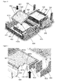
- Fig. 1
- shows a perspective view of a guiding frame of a device according to the invention;
- Fig. 2
- shows a perspective view of the guiding frame shown in
Fig. 1 as well as first lower component of the device according to the invention comprising a container for receiving a filter plate and a graft frame in which the hydrogel layer resides; - Fig. 3
- shows a perspective view of the filter plate that is to be arranged in said container and the first component being arranged on the guiding frame;
- Fig. 4
- shows a perspective view of a second upper component of the device according to the invention for compressing the hydrogel layer;
- Fig. 5
- shows a perspective view of the arrangement of the graft frame in said container on top of the filter plate;
- Fig. 6
- shows the fastening of a piston to the second component as well as said first component holding the filter plate and the graft frame;
- Fig. 7
- shows a perspective view of a detail of the second component and the piston connected thereto;
- Fig. 8
- shows a further perspective view of a detail of the second component;
- Fig. 9
- shows a perspective view of the second component upon arrangement of the latter on the first component and on the guiding frame;
- Fig. 10
- shows a cross section of the device according to the invention in an operating mode;
- Fig. 11
- shows a detail of the cross section shown in
Fig. 10 ; - Fig. 12
- shows a perspective view of the piston upon lifting it from the hydrogel layer in the graft frame;
- Fig. 13-16
- shows perspective views of a flask for incubating the compressed hydrogel layer.
-
Figs. 1 to 16 show a device for compressing a hydrogel H. The device comprises a guidingframe 100 being designed for holding/guiding a first and asecond component second component 400 can press with apiston 600 along a compression direction C against a hydrogel layer H arranged in agraft frame 500 positioned on thefirst component 200 in a guided manner. - As shown in
Fig. 1 said guidingframe 100 comprises arectangular frame member 103 formed out of four legs that are connected to each other in four corner regions of theframe member 103, wherein saidframe member 103 extends or is positioned on an underlayment - when the device or guidingframe 100 resides in an operating mode - along a horizontal plane, and wherein from each corner region of the frame member 103 a guidingrod 104 protrudes from theframe member 103 counter to said compression direction C that is oriented perpendicular to said horizontal plane. - As shown in
Fig. 2 saidfirst component 200 comprises arectangular base 201 comprising acircumferential edge region 202 in which fouropenings 204 are formed, namely one in each corner region of thebase 201 of thefirst component 200. Each opening is designed to receive one of the guidingrods 104 of the guiding frame, so that said guidingrods 104 extend through theirrespective opening 204 of thebase 201 of the first component, when the first component is arranged on top of the guidingframe 100 as shown inFig. 3 . Further, as illustrated inFig. 2 , the guidingframe 100 comprises twohandles 102 protruding from opposite legs of theframe member 103 of the guidingframe 100. Thesehandles 102 serve for moving or carrying the guidingframe 100, particularly together with the first and thesecond component - The
base 201 of thefirst component 200 further comprises a first orupper side 201a from which acircumferential wall 203 protrudes so that a central portion of thebase 201, e.g. a bottom 230, as well as saidwall 203 form acontainer 220 for receiving afilter plate 300 and agraft frame 500 on top of the filter plate as indicated inFigs. 3 ,5 and6 . - The
graft frame 500, which is e.g. shown inFig. 5 comprises a circumferential (e.g. rectangular)frame member 502 and a membrane bottom 501 (i.e. a bottom forming a membrane) connected to saidframe member 502, wherein thegraft frame 500 is designed to receive a hydrogel so that a hydrogel layer H is formed covering saidmembrane bottom 501 The membrane preferably consists of PET, is 18 micrometers thick and microporous, with a pore-diameter of preferably 3 micrometers. - Advantageously, the graft frame with its
membrane bottom 501 can be used for compressing the hydrogel as well as a carrier for holding the hydrogel after compression, e.g. during incubation. Advantageously, during incubation, a cell culture medium can reach the hydrogel layer from below (through the membrane bottom) as well as from above. - Further, the
frame member 502 of thegraft frame 500 comprises an uppercircumferential edge region 503 as well asregions 504 protruding from each of the four legs of theframe member 502. - The
filter plate 300 has a rectangular outer contour and is arranged such in thecontainer 220 of thefirst component 200 that an outer circumferential edge of the filter plate rests on astep 205 of thewall 203 of thecontainer 220 as shown inFigs. 3 and5 . Thegraft frame 500 is placed on top of thefilter plate 300 so that themembrane bottom 501 of thegraft frame 500 rests on thefilter plate 300, and such that the uppercircumferential edge region 503 of thegraft frame 500 rests on anupper edge 206 of thewall 203 of the graft frame, wherein said protrudingregions 504 of thegraft frame 500 engage withcorresponding recesses 207 formed in saidupper edge 206 of thewall 203 of thecontainer 220 in a form-fitting manner. - Upon compression of the hydrogel layer H, which will be described below, excess water W is pressed through the
membrane bottom 501 of the graft frame and flows through saidfilter plate 300 supporting themembrane bottom 501 into thecontainer 220 where it accumulates on thebottom 230 of thecontainer 220 as shown inFig. 10 , for instance. - In order to remove the graft frame as well as the filter plate from the
container 220, thewall 203 of the container comprises abulge 208 as shown inFig. 2 that allows for manually removing thegraft frame 500 as well as thefilter plate 300 from thecontainer 220, e.g., by means of a finger. - When the
graft frame 500 is arranged in thecontainer 220 as intended (cf.Fig. 6 ), thesecond component 400 is used to compress the hydrogel layer H along the compression direction C as shown inFig. 10 . - As illustrated in
Fig. 4 thesecond component 400 comprises a base 401 comprising acircumferential edge region 403 in which fouropening 404 are formed, i.e. oneopening 404 in each corner region of thebase 401 of thesecond component 400. Each of theseopenings 404 receives an associated guidingrod 104 when thesecond component 400 is arranged on the first component 200 (cf.Fig. 9 ) so that a movement of thesecond component 400 towards thefirst component 100 takes place precisely in the compression direction C. - Before arranging the
second component 400 on the first component 200 aseparate piston 600 is arranged on asupport 402 of thesecond component 400 which protrudes from a first orlower side 401 a of thebase 401 of thesecond component 400 along the compression direction C, and which comprises a first orlower side 402a facing the hydrogel layer H in the operating mode of the device according to the invention, wherein saidfirst side 402a extends perpendicular to the compression direction C. - The
piston 600 comprises a plate-like (e.g. rectangular)piston base 601 having a first orlower side 601 a extending perpendicular to the compression direction C, wherein saidfirst side 601 a forms a contact surface of thepiston 600 for pressing against the hydrogel layer H as well as acircumferential edge region 602 for contacting thewall 203 of thecontainer 220 from within in a sealing manner when thecontact surface 601 a presses against the hydrogel layer H, so that the hydrogel H stays inside thecontainer 220 and cannot getpast piston 600. - For connecting the
piston 600 to thesupport 402 of thesecond component 400, thepiston 600 comprises two latchingelements 603 and a plurality of guidingelements 604 protruding from thecircumferential edge region 602 as well as from asecond side 601 b of thepiston base 601 facing away from saidcontact surface 601 a, wherein saidlatching elements 603 are designed to engage with thesupport 402 to releasably fasten thepiston 600 to thesupport 402, and wherein said guidingelements 604 are designed to guide thepiston 600 with respect to thesupport 402 upon engaging the latchingelements 603 with the support 402 (cf.Fig. 6 ). When thepiston 600 is fastened to thesupport 402 by means of the latchingelements 604 thesecond side 601 b of thepiston base 601 extends along or butts against thefirst side 402a of the support 402 (cf.Figs. 7 and10 ). - In order to order to adjust a penetration depth of the piston 6 into the
graft frame 500, i.e., the thickness of the compressed hydrogel layer H, along the compression direction C, the second component comprises two screws shown inFig. 4 that are screwn in an internal thread formed in thefirst side 401 a of the base of thesecond component 400 adjacent to corner regions of thesupport 402, wherein said corner regions face each other diagonally. - As can be seen from
Figs. 10 and 11 , the screw heads of thesescrews 410 rest on theupper edge region 503 of theframe member 502 of the graft frame 500 (see position A inFig. 11 ), when thecontact surface 601 a of thepiston 600 connected to thesecond component 400 presses under guidance of the guidingrods 104 against the hydrogel layer H residing on themembrane bottom 501 of thegraft frame 500. Thus, the more these screw heads protrude from thefirst side 401 a of thebase 401 of the second component, the thicker the compressed hydrogel H layer becomes (see position T inFig. 11 ). - For force for compressing the hydrogel layer is provided by the weight of the second component and the parts attached thereto (e.g. the piston 600).
- For adjusting said weight, the
second component 400 comprises areceptacle 430 on asecond side 401 b of the base 401 facing away from saidfirst side 401 a, which receptacle 430 is formed or delimited by saidsupport 402 for supporting thepiston 600.Said receptacle 430 is designed to receive one orseveral weight elements 800 by means of which the overall weight of thesecond component 400 including thepiston 600 can be adjusted (cf.Figs. 9 and10 ). - After having compressed the hydrogel layer H as intended by means of the device according to the invention, the
second component 400 is removed from thefirst component 200 and the guidingframe 100. For this, thebase 401 of thesecond component 400 comprisesapertures 420 via which the latchingelements 603 are accessible from thesecond side 401 b of the basis, e.g. by means of a finger, so that saidlatching elements 603 can be brought out of their engagement with thesupport 402 of the second component 400 (cf.Figs. 8 and 9 ). - Than one has the
piston 600 released from thesecond component 400, whichpiston 600 usually sticks to the hydrogel layer H in thegraft frame 500. Thepiston 600 is then manually lifted from thegraft frame 500 as shown inFig. 12 . - According to an embodiment of the present invention, the
membrane bottom 501 inside thegraft frame 500 as well as saidcontact surface 601 a of thepiston 600 each comprise an area of 6cm x 7cm. Other sizes are also possible. Thus the final compressed hydrogel layer comprises a corresponding area of e.g. 6cm x 7cm and a thickness defined byscrews 410, see above. - For further treatment of the compressed hydrogel layer H a
flask 700 for incubation of the compressed hydrogel layer H is provided (cf.Figs. 13 to 16 ). Theflask 700 is designed to receive thegraft frame 500 with the compressed hydrogel layer H residing in saidgraft frame 500. For this, theflask 700 comprises anopening 704 in atop part 703 of theflask 700 through which thegraft frame 500 is arranged in an interior of theflask 700 as shown inFig. 14 . In beforehand, as shown inFig. 13 , asupport frame 706 is arranged on abottom 702 of theflask 700 through itsopening 704 for supporting thegraft frame 500. Thesupport frame 706 comprisesrecesses 707 formed in an upper edge of thesupport frame 706 for receiving saidportions 504 of theframe member 502 of thegraft frame 500, wherein thegraft frame 500 is designed to rest with itsupper edge region 503 on said upper edge of thesupport frame 706. Particularly, thesupport frame 706 rests with fourstands 709 on said bottom. Furthermore, thesupport frame 706 comprises two opposing protrudingregions 708 for contacting awall 702 of theflask 700 from the interior of theflask 700 so that thesupport frame 706 cannot be displaced inside theflask 700 in a lateral direction (cf.Figs. 14 and 15 ). - Once the
graft frame 500 is properly positioned in thesupport frame 706 inside theflask 700, theopening 704 of the flask is closed by means of alid 710 which then presses the graft frame into thesupport frame 706 so that the graft frame is fixed along in a direction perpendicular tobottom 701 of the flask between thelid 710 and thesupport frame 706. It is also possible to arrange an additional element between saidlid 710 and thegraft frame 500 in order to press the graft frame against thesupport frame 706 by means of thelid 710. - Through a further opening that can be closed by a screw cap, a cell culture medium can be filled into the flask. The cell culture medium is required for both, the culture of the cells in and on the hydrogel layer, and for transportation of the dermo-epidermal grafts made from the hydrogel layer.
- Preferably, the guiding
frame 100 is made out of a stainless steel. - Further, the
first component 200 is preferably made out of PEEK (Polyether ether ketone). - Further, the
second component 400 is preferably made out of PEEK (Polyether ether ketone). - Further, the
membrane bottom 501 of thegraft frame 500 is preferably made out of PET (e.g. according to ISO 13485). - Furthermore, the
piston 600 is preferably made out of Polypropylene. -
- [1] Diezi, Mirco, Determining the conditions that regulate epidermal stratification in vitro: Engineering an epidermal substitute in 3 steps, Master Thesis in Human Biology, Tissue Biology Research Unit, University of Zürich, February 2009;
- [2] Baroli, B., Hydrogels for tissue engineering and delivery of tissue-inducing substances. J Pharm Sci, 2007. 96(9): p. 2197-223.
- [3] Mimura, T., et al., Tissue engineering of corneal stroma with rabbit fibroblast precursors and gelatin hydrogels. Mol Vis, 2008. 14: p. 1819-28.
- [4] Stark, H.J., et al., Organotypic keratinocyte cocultures in defined medium with regular epidermal morphogenesis and differentiation. Journal of Investigative Dermatology, 1999. 112(5): p. 681-691.
- [5] Yamaoka, H., et al., Cartilage tissue engineering using human auricular chondrocytes embedded in different hydrogel materials. J Biomed Mater Res A, 2006. 78(1): p. 1-11.
- [6] Ferguson, R.E. and B. Rinker, The use of a hydrogel sealant on flexor tendon repairs to prevent adhesion formation. Ann Plast Surg, 2006. 56(1): p. 54-8.
Claims (15)
- Device for compressing a hydrogel, comprising- a separate graft frame (500) comprising a circumferential frame member (502) and a membrane bottom (501) connected to said frame member (502), wherein the graft frame (500) is designed to receive said hydrogel (H) so that a hydrogel layer (H) is formed covering said membrane bottom (501),- a guiding frame (100) having a plurality of guiding rods (104) extending along a compression direction (C),- a filter plate (300),- a first component (200) comprising a base (201) having a plurality of openings (204), particularly formed in an edge region (202) of said base (201), wherein each opening (204) is associated to one of the guiding rods (104), wherein the first component (200) is designed to be arranged on the guiding frame (100) in an operating mode of the device such that each guiding rod (104) extends through its associated opening (204), wherein the first component (200) further comprises a circumferential wall (203) protruding from said base (201) of the first component (200), so that the first component (200) forms a container (220) that is designed to receive the filter plate (300) and the graft frame (500) in said operating mode so that the filter plate (300) is arranged between a bottom (230) of said container (220) and the membrane bottom (501) of the graft frame (500),- a second component (400) comprising a base (401) having a plurality of openings (404), particularly formed in an edge region (403) of said base (401) of the second component (400), wherein each opening (404) is associated to one of the guiding rods (104), wherein the second component (400) is designed to be arranged on said first component (200) in said operating mode, such that each guiding rod (104) that extends through its associated opening (204) of the first component (200) is also inserted into its associated opening (404) of the second component (400) so that the second component is guided by said rods (104) along the compression direction (C),- a separate piston (600) that is designed to be connected to said second component (400) in a releasable manner in said operating mode of the device, particularly by means of a latching connection, wherein in said operating mode the second component (400) is designed to press the piston (600) along the compression direction (C) against said hydrogel layer (H) residing on the membrane bottom (501) of the graft frame (500) so as to compress the hydrogel layer (H) between the piston (600) and the membrane bottom (501).
- Device according to claim 1, characterized in that the graft frame (500) and/or the piston (600) are designed as single-use items.
- Device according to claim 1 or 2, characterized in that the piston (600) comprises a piston base (601) having a first side (601 a) forming a contact surface for pressing against the hydrogel layer (H), wherein particularly the piston (600) is designed to be inserted into the graft frame (500) with its contact surface (601a) ahead when pressing with its contact surface (601a) against the hydrogel layer (H), wherein particularly the piston base (601) comprises a circumferential edge region (602) being designed to contact the frame member (502) of the graft frame (500) when pressing against the hydrogel layer (H).
- Device according to one of the preceding claims, characterized in that the piston (600) comprises two latching elements (603), particularly protruding from said edge region (602) of the piston base (601) on a second side (601 b) of the piston base (601) facing away from said first side (601 a) forming said contact surface.
- Device according to one of the preceding claims, characterized in that the second component (400) comprises a support (402) for the piston (600), which support (402) protrudes from a first side (401 a) of the base (401) of the second component (400) towards the membrane bottom (501) in said operating mode of the device, wherein particularly the latching elements (603) are designed to engage with said support (402) for releasably connecting the piston (600) to the support (402).
- Device according to one of the claims 4 to 5, characterized in that the base (401) of the second component (400) comprises an aperture (420) for each latching element (603), through which the respective latching element (603) is accessible from a second side (401 b) of the base (401) of the second component (400) facing away from said first side (401 a) of the base (401) of the second component (400), so that particularly the latching elements (603) can be released from the support (402) manually via said apertures (420).
- Device according to one of the preceding claims, characterized in that the piston (600) comprises guiding elements (604) protruding from said edge region (602) of the piston base (601) on said second side (601 b) of the piston base (601) facing away from said contact surface (601 a), which guiding elements (604) are designed to slide along said support (402) for guiding the piston (600) with respect to the support (402) upon engaging the latching elements (603) with the support (402).
- Device according to one of the preceding claims, characterized in that the second component comprises an adjusting means for adjusting a penetration depth of the piston (600) along the compression direction (C) into the graft frame (500), wherein particularly said adjusting means comprises two screws (410) that are screwed in an internal thread formed in the first side (401 a) of the base (401) adjacent to the support (402), so that the heights of the screw heads of said screws (410) with respect to said first side (401 a) the base (401) can be adjusted by turning the respective screw (410) clockwise or counterclockwise, wherein the screw heads (410) are designed to rest on said frame member (502) in the operating mode of the device so as to limit said penetration depth.
- Device according to one of the preceding claims, characterized in that the base (401) of the second component (400) comprises a receptacle (430) for receiving at least one weight element (800), so as to adjust the weight of the second component (400), by means of which the second component (400) compresses said hydrogel layer (H) in said operating mode of the device, wherein particularly said receptacle (430) is formed by said support (402), wherein particularly said receptacle (430) comprises an opening on the second side (401 b) of the base (401) of the second component (400), via which opening said at least one weight element (800) can be arranged in said receptacle (430).
- Device according to one of the preceding claims, characterized in that said circumferential wall (203) of the container (220) comprises a step (205) for supporting said filter plate (300).
- Device according to one of the preceding claims, characterized in that said graft frame (500) is designed to rest with a circumferential edge region (503) of the frame member (502) on an upper edge (206) of the wall (203) of the container (220) in said operating mode of the device, wherein particularly said upper edge (206) of the wall (203) comprises at least one recess (207) for receiving a region (504) of the frame member (502) of the graft frame (500) in a form-fitting manner.
- Device according to one of the preceding claims, characterized in that said wall (203) comprises a bulge (208) for taking the filter plate (300) and/or the graft frame (500) out of the container (220).
- System comprising a device according to one of the preceding claims, characterized in that the system further comprises a flask (700) for incubation of the compressed hydrogel layer (H), wherein said flask (700) is designed to receive the graft frame (500) with the compressed hydrogel layer (H) residing in said graft frame (500), wherein particularly the flask (700) comprises an opening (704) through which the graft frame (500) can be arranged in an interior of the flask (700), wherein particularly the flask (700) comprises a lid (710) for closing said opening (704), wherein particularly said system comprises a support frame (706) being designed to be arranged in said interior of the flask (700) on a bottom (701) of the flask (700) and to support the graft frame (500), wherein the lid (710) is designed to press the graft frame (500) against the support frame (706) when the lid (710) closes said opening (704) of the flask (700), and wherein the flask (700) comprises a further opening for filling a liquid, particularly a cell culture medium, into the flask (700), and wherein particularly a screw cap (705) is provided for closing said further opening, and wherein particularly said flask (700) is transparent at least in sections, and wherein particularly said flask (700) and/or the support frame (706) are designed as single-use items.
- System comprising at least a graft frame (500), the graft frame (500) comprising a circumferential frame member (502) and a membrane bottom (501) connected to said frame member (502), wherein the graft frame (500) is designed to receive a hydrogel (H) so that a hydrogel layer (H) is formed covering said membrane bottom (501), wherein particularly the membrane bottom (501) is integrally connected to the frame member (502), wherein particularly the graft frame (500) is designed as a single-use item, wherein particularly the graft frame (500) is designed to be inserted into a container (220) of a device for compressing a hydrogel layer (H) residing on the membrane bottom (501), wherein particularly said device is the device according to one of the claims 1 to 12, and wherein particularly said system further comprises a flask (700) for incubation of the compressed hydrogel layer (H) residing in the graft frame (500) on the membrane bottom (501), wherein particularly said flask (700) is designed to receive the graft frame (500) with the compressed hydrogel layer (H) residing in said graft frame (500) on the membrane bottom (501), wherein particularly the flask (700) comprises an opening (704) through which the graft frame (500) can be arranged in an interior of the flask (700), wherein particularly the flask (700) comprises a lid (710) for closing said opening (704), wherein particularly said system comprises a separate support frame (706) being designed to be arranged in said interior of the flask (700) on a bottom (701) of the flask (700) and to support the graft frame (500), wherein the lid (710) is designed to press the graft frame (500) against the support frame (706) when the lid (710) closes said opening (704) of the flask (700), and wherein the flask (700) comprises a further opening for filling a liquid, particularly a cell culture medium, into the flask (700), and wherein particularly a screw cap (705) is provided for closing said further opening, and wherein particularly said flask (700) is transparent at least in sections, and wherein particularly said flask (700) and/or the support frame (706) are designed as single-use items.
- Method for compressing a hydrogel layer, particularly for generating an artificial skin graft, using a device according to one of the claims 1 to 12 or a system according to claim 13, comprising the steps of:- filling a hydrogel (H), particularly containing fibroblasts, into the graft frame (500) so that said hydrogel (H) forms a hydrogel layer (H) covering said membrane bottom (501), particularly incubating the hydrogel layer (H) residing in the graft frame (500),- arranging the filter plate (300) in said container (220) of the first component (200),- arranging said graft frame (500) comprising the hydrogel layer (H) in said container (220) on top of the filter plate (300),- arranging the first component (200) on the guiding frame (100) so that the guiding rods (104) extend through their respective opening (204) of the first component (200),- arranging the second component (400) on the first component (200) so that said guiding rods (104) are inserted into their respective opening (404) of the second component (400),- compressing the hydrogel layer (H) between the membrane bottom (501) and the piston (600) connected to the second (400) component by letting the second component (400) press with the piston (600) along the compression direction (C) against the hydrogel layer (H), wherein the second component (400) is guided by said guiding rods (104) along the compression direction (C), and- particularly removing the graft frame (500) from the first component (200) and the second component (400) after having compressed the hydrogel layer (H),- particularly arranging the graft frame (500) with the compressed hydrogel layer (H) through an opening (704) of a flask (700) in an interior of said flask (700) on top of a support frame (706) arranged on a bottom (701) of the flask (700),- particularly closing the opening (704) of the flask (700) with a lid (710), thereby pressing the frame member (502) of the graft frame (500) with the lid (710) against the frame support (706), so as to secure the graft frame (500) in the flask (700), and- particularly filling a cell culture medium into the flask (700),- particularly incubating the compressed hydrogel layer (H),- particularly adding keratinocytes to an upper surface of the hydrogel layer (H), which upper surface faces away from the membrane bottom (501).
Priority Applications (11)
| Application Number | Priority Date | Filing Date | Title |
|---|---|---|---|
| EP20130174441 EP2818186A1 (en) | 2013-06-28 | 2013-06-28 | Device and method for compressing a hydrogel |
| CA2915777A CA2915777C (en) | 2013-06-28 | 2014-06-27 | Device and method for compressing a hydrogel |
| US14/901,108 US10195310B2 (en) | 2013-06-28 | 2014-06-27 | Device and method for compressing a hydrogel |
| ES14733647T ES2698968T3 (en) | 2013-06-28 | 2014-06-27 | Device and procedure for compressing a hydrogel |
| BR112015032714-1A BR112015032714B1 (en) | 2013-06-28 | 2014-06-27 | HYDROGEL COMPRESSION DEVICE, SYSTEM UNDERSTANDING A DEVICE, SYSTEM UNDERSTANDING AT LEAST ONE GRAFT FRAME, AND HYDROGEL LAYER COMPRESSION METHOD |
| AU2014300923A AU2014300923B2 (en) | 2013-06-28 | 2014-06-27 | Device and method for compressing a hydrogel |
| EP14733647.3A EP3013381B1 (en) | 2013-06-28 | 2014-06-27 | Device and method for compressing a hydrogel |
| PCT/EP2014/063786 WO2014207251A2 (en) | 2013-06-28 | 2014-06-27 | Device and method for compressing a hydrogel |
| JP2016522551A JP6494613B2 (en) | 2013-06-28 | 2014-06-27 | Apparatus and method for compressing hydrogels |
| CN201480036454.2A CN105377317B (en) | 2013-06-28 | 2014-06-27 | For compressing the device and method of hydrogel |
| ZA2015/09185A ZA201509185B (en) | 2013-06-28 | 2015-12-17 | Device and method for compressing a hydrogel |
Applications Claiming Priority (1)
| Application Number | Priority Date | Filing Date | Title |
|---|---|---|---|
| EP20130174441 EP2818186A1 (en) | 2013-06-28 | 2013-06-28 | Device and method for compressing a hydrogel |
Publications (1)
| Publication Number | Publication Date |
|---|---|
| EP2818186A1 true EP2818186A1 (en) | 2014-12-31 |
Family
ID=48703230
Family Applications (2)
| Application Number | Title | Priority Date | Filing Date |
|---|---|---|---|
| EP20130174441 Withdrawn EP2818186A1 (en) | 2013-06-28 | 2013-06-28 | Device and method for compressing a hydrogel |
| EP14733647.3A Active EP3013381B1 (en) | 2013-06-28 | 2014-06-27 | Device and method for compressing a hydrogel |
Family Applications After (1)
| Application Number | Title | Priority Date | Filing Date |
|---|---|---|---|
| EP14733647.3A Active EP3013381B1 (en) | 2013-06-28 | 2014-06-27 | Device and method for compressing a hydrogel |
Country Status (10)
| Country | Link |
|---|---|
| US (1) | US10195310B2 (en) |
| EP (2) | EP2818186A1 (en) |
| JP (1) | JP6494613B2 (en) |
| CN (1) | CN105377317B (en) |
| AU (1) | AU2014300923B2 (en) |
| BR (1) | BR112015032714B1 (en) |
| CA (1) | CA2915777C (en) |
| ES (1) | ES2698968T3 (en) |
| WO (1) | WO2014207251A2 (en) |
| ZA (1) | ZA201509185B (en) |
Cited By (1)
| Publication number | Priority date | Publication date | Assignee | Title |
|---|---|---|---|---|
| CN111868227A (en) * | 2018-03-12 | 2020-10-30 | Cecs干细胞研究中心 | Method and device for preparing implants obtained from stem cell cultures |
Families Citing this family (3)
| Publication number | Priority date | Publication date | Assignee | Title |
|---|---|---|---|---|
| KR20180094941A (en) * | 2015-12-04 | 2018-08-24 | 프레지던트 앤드 펠로우즈 오브 하바드 칼리지 | Open-top microfluidic device and method for simulating the function of tissue |
| WO2021176443A1 (en) * | 2020-03-02 | 2021-09-10 | Cutiss Ag | Disposable system and method for preparing a compressed hydrogel |
| AU2022296956A1 (en) * | 2021-06-20 | 2024-01-18 | Cutiss Ag | Tissue culture vessel for preparation of compressed hydrogel skin grafts and related methods and systems |
Citations (3)
| Publication number | Priority date | Publication date | Assignee | Title |
|---|---|---|---|---|
| WO2012004564A1 (en) * | 2010-07-07 | 2012-01-12 | Ucl Business Plc | Plastic compaction of a collagen gel |
| US20120288911A1 (en) * | 2011-05-12 | 2012-11-15 | Empire Technology Development LLC a Limited Liability Company | Bioreactor for engineered tissue |
| US20130099407A1 (en) * | 2010-06-10 | 2013-04-25 | Francis Michael Neves Zuzarte Tully | Apparatus, Kits and Methods for the Production of Biomimetic Constructs |
Family Cites Families (2)
| Publication number | Priority date | Publication date | Assignee | Title |
|---|---|---|---|---|
| US5882929A (en) | 1998-04-07 | 1999-03-16 | Tissue Engineering, Inc. | Methods and apparatus for the conditioning of cartilage replacement tissue |
| ZA200602094B (en) | 2006-01-16 | 2007-11-28 | Reliance Life Sciences Pvt Ltd | Device for culturing and transporting cells |
-
2013
- 2013-06-28 EP EP20130174441 patent/EP2818186A1/en not_active Withdrawn
-
2014
- 2014-06-27 AU AU2014300923A patent/AU2014300923B2/en active Active
- 2014-06-27 JP JP2016522551A patent/JP6494613B2/en active Active
- 2014-06-27 WO PCT/EP2014/063786 patent/WO2014207251A2/en active Application Filing
- 2014-06-27 CA CA2915777A patent/CA2915777C/en active Active
- 2014-06-27 CN CN201480036454.2A patent/CN105377317B/en active Active
- 2014-06-27 US US14/901,108 patent/US10195310B2/en active Active
- 2014-06-27 BR BR112015032714-1A patent/BR112015032714B1/en active IP Right Grant
- 2014-06-27 EP EP14733647.3A patent/EP3013381B1/en active Active
- 2014-06-27 ES ES14733647T patent/ES2698968T3/en active Active
-
2015
- 2015-12-17 ZA ZA2015/09185A patent/ZA201509185B/en unknown
Patent Citations (3)
| Publication number | Priority date | Publication date | Assignee | Title |
|---|---|---|---|---|
| US20130099407A1 (en) * | 2010-06-10 | 2013-04-25 | Francis Michael Neves Zuzarte Tully | Apparatus, Kits and Methods for the Production of Biomimetic Constructs |
| WO2012004564A1 (en) * | 2010-07-07 | 2012-01-12 | Ucl Business Plc | Plastic compaction of a collagen gel |
| US20120288911A1 (en) * | 2011-05-12 | 2012-11-15 | Empire Technology Development LLC a Limited Liability Company | Bioreactor for engineered tissue |
Non-Patent Citations (6)
Cited By (2)
| Publication number | Priority date | Publication date | Assignee | Title |
|---|---|---|---|---|
| CN111868227A (en) * | 2018-03-12 | 2020-10-30 | Cecs干细胞研究中心 | Method and device for preparing implants obtained from stem cell cultures |
| CN111868227B (en) * | 2018-03-12 | 2024-04-12 | Cecs干细胞研究中心 | Method and device for producing an implant obtained from a stem cell culture |
Also Published As
| Publication number | Publication date |
|---|---|
| AU2014300923A1 (en) | 2016-01-21 |
| JP6494613B2 (en) | 2019-04-03 |
| CN105377317B (en) | 2019-09-27 |
| EP3013381B1 (en) | 2018-08-22 |
| BR112015032714A2 (en) | 2017-07-25 |
| AU2014300923B2 (en) | 2019-02-28 |
| JP2016523158A (en) | 2016-08-08 |
| ZA201509185B (en) | 2017-03-29 |
| CA2915777A1 (en) | 2014-12-31 |
| EP3013381A2 (en) | 2016-05-04 |
| CN105377317A (en) | 2016-03-02 |
| WO2014207251A2 (en) | 2014-12-31 |
| WO2014207251A3 (en) | 2015-03-12 |
| CA2915777C (en) | 2021-11-23 |
| ES2698968T3 (en) | 2019-02-06 |
| US20160136333A1 (en) | 2016-05-19 |
| BR112015032714B1 (en) | 2020-12-15 |
| US10195310B2 (en) | 2019-02-05 |
Similar Documents
| Publication | Publication Date | Title |
|---|---|---|
| EP3013381B1 (en) | Device and method for compressing a hydrogel | |
| McMahon et al. | Regulatory effects of mechanical strain on the chondrogenic differentiation of MSCs in a collagen-GAG scaffold: experimental and computational analysis | |
| JP7370370B2 (en) | Surface topography to alter the physiology of living cells | |
| JP7361039B2 (en) | Ex vivo subcutaneous injection model | |
| WO2011154686A1 (en) | Apparatus, kits and methods for the production of biomimetic constructs | |
| Shukla et al. | Acellular dermis as a dermal matrix of tissue engineered skin substitute for burns treatment | |
| KR20130111347A (en) | Cultured cartilage tissue material | |
| US20230114908A1 (en) | Disposable system and method for preparing a compressed hydrogel | |
| JP6480192B2 (en) | Method for perfusion of fluid in vascular bed and apparatus for performing the method | |
| CN111686309A (en) | Preparation method of 3D printed skin | |
| WO2015009071A1 (en) | Body volume substitute comprising cartilage for grafting by injection, and dual needle-type syringe for injecting same | |
| McCarty et al. | The proteoglycan metabolism of articular cartilage in joint-scale culture | |
| BABA et al. | Combined automated culture system for tubular structure assembly and maturation for vascular tissue engineering | |
| Woodroof et al. | The search for an ideal temporary skin substitute: AWBAT Plus, a combination product wound dressing medical device | |
| Kalyanaraman | Bioreactors to Demonstrate Process Automation and Regulate Physiology of Engineered Skin Substitutes | |
| BE | The Role of Matrix Properties and Extrinsic Loading in Osteoblast-Osteocyte Differentiation in Tissue Engineered Scaffolds | |
| WO2014111518A1 (en) | Tissue bioreactor | |
| Robertson | Optical Coherence Tomography Imaging of Tissue Engineered Skin Cultured Under Perfusion Conditions |
Legal Events
| Date | Code | Title | Description |
|---|---|---|---|
| PUAI | Public reference made under article 153(3) epc to a published international application that has entered the european phase |
Free format text: ORIGINAL CODE: 0009012 |
|
| 17P | Request for examination filed |
Effective date: 20130628 |
|
| AK | Designated contracting states |
Kind code of ref document: A1 Designated state(s): AL AT BE BG CH CY CZ DE DK EE ES FI FR GB GR HR HU IE IS IT LI LT LU LV MC MK MT NL NO PL PT RO RS SE SI SK SM TR |
|
| AX | Request for extension of the european patent |
Extension state: BA ME |
|
| STAA | Information on the status of an ep patent application or granted ep patent |
Free format text: STATUS: THE APPLICATION IS DEEMED TO BE WITHDRAWN |
|
| 18D | Application deemed to be withdrawn |
Effective date: 20150701 |