EP2817609B1 - Tissue specimen stage for an optical sectioning microscope - Google Patents
Tissue specimen stage for an optical sectioning microscope Download PDFInfo
- Publication number
- EP2817609B1 EP2817609B1 EP13751395.8A EP13751395A EP2817609B1 EP 2817609 B1 EP2817609 B1 EP 2817609B1 EP 13751395 A EP13751395 A EP 13751395A EP 2817609 B1 EP2817609 B1 EP 2817609B1
- Authority
- EP
- European Patent Office
- Prior art keywords
- window
- tissue specimen
- carriage
- along
- curvature
- Prior art date
- Legal status (The legal status is an assumption and is not a legal conclusion. Google has not performed a legal analysis and makes no representation as to the accuracy of the status listed.)
- Active
Links
- 230000003287 optical effect Effects 0.000 title claims description 50
- 230000033001 locomotion Effects 0.000 claims description 33
- 238000003384 imaging method Methods 0.000 claims description 20
- 238000000034 method Methods 0.000 claims description 15
- 238000013519 translation Methods 0.000 claims description 12
- 230000006835 compression Effects 0.000 description 15
- 238000007906 compression Methods 0.000 description 15
- 238000001356 surgical procedure Methods 0.000 description 12
- 230000007246 mechanism Effects 0.000 description 11
- 206010028980 Neoplasm Diseases 0.000 description 10
- 239000012528 membrane Substances 0.000 description 10
- 239000000523 sample Substances 0.000 description 5
- 238000012014 optical coherence tomography Methods 0.000 description 4
- 239000012530 fluid Substances 0.000 description 3
- 238000001727 in vivo Methods 0.000 description 3
- 239000007788 liquid Substances 0.000 description 3
- 239000000463 material Substances 0.000 description 3
- 238000000386 microscopy Methods 0.000 description 3
- 238000012634 optical imaging Methods 0.000 description 3
- 230000001575 pathological effect Effects 0.000 description 3
- 238000002360 preparation method Methods 0.000 description 3
- 238000003825 pressing Methods 0.000 description 3
- 210000002105 tongue Anatomy 0.000 description 3
- XUMBMVFBXHLACL-UHFFFAOYSA-N Melanin Chemical compound O=C1C(=O)C(C2=CNC3=C(C(C(=O)C4=C32)=O)C)=C2C4=CNC2=C1C XUMBMVFBXHLACL-UHFFFAOYSA-N 0.000 description 2
- 238000001069 Raman spectroscopy Methods 0.000 description 2
- 239000000853 adhesive Substances 0.000 description 2
- 230000001070 adhesive effect Effects 0.000 description 2
- 230000008901 benefit Effects 0.000 description 2
- 238000001574 biopsy Methods 0.000 description 2
- 230000000295 complement effect Effects 0.000 description 2
- 150000001875 compounds Chemical class 0.000 description 2
- 230000000694 effects Effects 0.000 description 2
- 238000005305 interferometry Methods 0.000 description 2
- 238000000370 laser capture micro-dissection Methods 0.000 description 2
- 239000002184 metal Substances 0.000 description 2
- 230000005855 radiation Effects 0.000 description 2
- 230000004044 response Effects 0.000 description 2
- 230000000717 retained effect Effects 0.000 description 2
- 230000003595 spectral effect Effects 0.000 description 2
- 238000010186 staining Methods 0.000 description 2
- 201000009030 Carcinoma Diseases 0.000 description 1
- 238000001530 Raman microscopy Methods 0.000 description 1
- 229920006328 Styrofoam Polymers 0.000 description 1
- 239000002313 adhesive film Substances 0.000 description 1
- 230000000712 assembly Effects 0.000 description 1
- 238000000429 assembly Methods 0.000 description 1
- 201000009310 astigmatism Diseases 0.000 description 1
- 230000005540 biological transmission Effects 0.000 description 1
- 230000008859 change Effects 0.000 description 1
- 238000012512 characterization method Methods 0.000 description 1
- 238000001344 confocal Raman microscopy Methods 0.000 description 1
- 238000010226 confocal imaging Methods 0.000 description 1
- 238000012937 correction Methods 0.000 description 1
- 201000010099 disease Diseases 0.000 description 1
- 208000037265 diseases, disorders, signs and symptoms Diseases 0.000 description 1
- 229920002457 flexible plastic Polymers 0.000 description 1
- 238000007710 freezing Methods 0.000 description 1
- 230000008014 freezing Effects 0.000 description 1
- 238000005259 measurement Methods 0.000 description 1
- 238000001000 micrograph Methods 0.000 description 1
- 238000012986 modification Methods 0.000 description 1
- 230000004048 modification Effects 0.000 description 1
- 210000000056 organ Anatomy 0.000 description 1
- 230000007170 pathology Effects 0.000 description 1
- 229920003023 plastic Polymers 0.000 description 1
- 239000004033 plastic Substances 0.000 description 1
- 238000004321 preservation Methods 0.000 description 1
- 238000012552 review Methods 0.000 description 1
- 239000008261 styrofoam Substances 0.000 description 1
- 239000000126 substance Substances 0.000 description 1
Images


Classifications
-
- G—PHYSICS
- G02—OPTICS
- G02B—OPTICAL ELEMENTS, SYSTEMS OR APPARATUS
- G02B21/00—Microscopes
- G02B21/24—Base structure
- G02B21/26—Stages; Adjusting means therefor
-
- G—PHYSICS
- G02—OPTICS
- G02B—OPTICAL ELEMENTS, SYSTEMS OR APPARATUS
- G02B21/00—Microscopes
- G02B21/34—Microscope slides, e.g. mounting specimens on microscope slides
Definitions
- the present invention relates to a tissue specimen stage for an optical sectioning microscope, and particularly to a stage (and method) for moving a window with surface curvature adapted to the curvature or shape of the edges and surfaces of a non-histologically prepared tissue specimen.
- the window is mounted to a container or tissue specimen receptacle that is positioned in a carriage movable along two rotational axes so that different locations along the window are presentable to the objective lens of a optical sectioning microscope for imaging the tissue specimen through the window.
- the stage may be used by other optical sectioning microscopes operable by two-photon or optical coherence tomography as well as microscopes that can detect the presence of endogenous fluorescence of tissue, fluorescence from exogenous compounds or Raman spectroscopic signatures of tissue.
- tissue having a tumor is excised from a patient under microscopic guidance.
- the excised tissue specimen often called a biopsy, is horizontally sliced to provide thin tissue sections that are then histologically prepared on slides.
- the slides are reviewed under a microscope to determine whether the tumor is fully contained in the excised tissue. This is indicated by the absence of the tumor in the edges or margins of the excised tissue. If the tumor is not fully contained in the excised tissue, additional tissue from the patient is excised and the procedure is repeated until all tissue sections taken indicate the tumor has been removed from the patient.
- Mohs surgery permits removal of a tumor with maximum preservation of normal surrounding tissue. Mohs surgery is described in the book entitled MOHS SURGERY FUNDAMENTALS AND TECHNIQUES (Kenneth G. Gross, M.D. et al. eds., 1999 ).
- each section is planar and parallel to each other.
- tissue specimen is first frozen to make the tissue easier to manipulate and cut by the microtome.
- this procedure is both tedious and time consuming.
- U.S. Patent No. 4,752,347 provides a method and apparatus for preparing a tissue specimen for sectioning for Mohs surgery.
- the patent describes placing an excised tissue specimen on a platform, applying a flexible plastic membrane over the tissue specimen, and evacuating the area between the membrane and the tissue specimen. This retracts the membrane onto the platform and pushes the edges of the tissue specimen into a planar orientation parallel to the platform. While under the pressure of the membrane, the tissue sections may be manipulated by an operator through the membrane until the desired orientation is obtained. The edges of the tissue specimen are thus oriented to flatten the edges of the specimen down. The specimen is then frozen, peeled away from the platform, and sectioned by a microtome.
- edges of the specimen are oriented planar when sectioned by the microtome, a single section can be made having the edges of interest in Mohs surgery. This procedure is adequate for obtaining a section which can be placed on a slide for review under a microscope, but is not useful with optical imaging techniques, such as provided by confocal microscopes, which can examine a surgically exposed tissue specimen without the need for traditional microtome sectioning or slide preparation.
- Confocal microscopes optically section tissue to produce microscopic images of tissue sections without requiring histological preparation of the tissue on slides (i.e., slicing, slide mounting, and staining).
- An example of a confocal microscope is the VivaScope® manufactured by Caliber Imaging Diagnostics, Inc. (formally Lucid Inc.) of Henrietta, New York. Other examples of confocal microscopes are described in U.S. Patent Nos.
- optically sectioned microscopic images of tissue can be produced by optical coherence tomography or interferometry, such as described in Schmitt et al., "Optical characterization of disease tissues using low-coherence interferometry," Proc. of SPIE, Volume 1889 (1993 ), or by a two-photon laser microscope, such as described in U.S. Patent No. 5,034,613 .
- Raman spectral signatures of molecules can be measured in the skin with optical sectioning microscopy, such as described by Peter J Caspers et al., “In Vivo Confocal Raman Microspectroscopy of the Skin: Noninvasive Determination of Molecular Concentration Profiles", Journal of Investigative Dermatology (2001) 116, 434-442 .
- confocal fluorescence microscopes such as Nikon Instruments AZ-C1 Macro Laser Confocal Imaging System that can image endogenous tissue fluorescence or the fluorescence of exogenous compounds that are applied to the tissue.
- tissue specimen for Mohs surgery such as by confocal microscope
- the tissue specimen is generally too thick, for example 2-3 mm, to image the edges of the specimen to determine if the specimen contains all of the tumor.
- Edges refer to areas along the tissue specimen where the cut was made in order to remove the tissue specimen from the patient that may or may not have the margins of the tumor.
- the excised tissue surface is generally convex. It is this convex surface that is needed to be examined to determine if tumor is present in the specimen.
- a confocal microscope is limited to producing adequate images of tissue sections at 100-200 microns.
- U.S. Patent No. 6,411,434 describes a cassette having a base member with a rigid optically transparent planar window upon which a tissue specimen is situated, and a pliable plastic membrane locatable over the window and a substantial portion of the base member.
- Document US 7,847,949 B2 relates to devices and methods for comprehensive optical imaging of epithelial organs and other biological structures via spectral encoding.
- a curved window similar to the window that induces the astigmatism can be placed in an optical path for efficient and accurate correction of this optical distortion.
- Document WO 00/15021 relates to imaging of biopsies (tissue specimens) and particularly to systems (methods and apparatus) for providing images of surgically removed tissue material from which images suitable for pathological examination, without delay for tissue preparation, such as freezing, sectioning, staining and mounting on microscope slides.
- Document WO 99/00658 relates to a convex geometry for the laser actuated adhesive film used to perform Laser Capture Microdissection (LCM) - a technique for removing minute amounts of tissue from pathology slides in a convenient, rapid manner.
- LCD Laser Capture Microdissection
- Document system WO 2011/094659 A2 relates to a system for margin assessment of an ex-vivo tissue including an imaging scanner controlled by an imaging control unit, and an ex-vivo sample holder for holding a sample of an excised tissue.
- the present invention embodies a tissue specimen stage having a window with surface curvature upon which an excised tissue specimen is locatable, a carriage to which the window is mounted, and a platform supporting the carriage and presenting the window to the objective lens of an optical sectioning microscope, i.e., a microscope that can optically form microscopic images of one or more sections under a tissue surface.
- the carriage is mounted to the platform for movement along two rotational axes so that the carriage's movement follows the curvature of all or part of the window while maintaining the same optical geometry of the window with respect to the objective lens.
- the window's surface curvature is adapted to at least approximate the shape or curvature of the non-histologically prepared tissue specimen to be placed thereupon.
- the window is rotationally symmetric by having the same radius of curvature, at least along the surface of the window having the tissue specimen.
- the window may instead have aspheric surface curvature, in which two or more regions of the window may be of different radius of curvature, and if so, the distance between the objective lens and the window is adjusted to maintain the same optical geometry between the window and the objective lens so that focus of the microscope is maintained as the window moves with respect to the objective lens. This may be achieved by moving the objective lens towards or away from the window, or moving the entire platform supporting the window, via the carriage, towards or away from the objective lens so as to maintain focus. Different windows may be selected for the shape of such edges desired to be imaged by the optical sectioning microscope.
- the axes of rotation of the stage are aligned with the surface curvature (radius) of the window in the case of a rotational symmetric window so that the stage's rotationally motion follows the curvature of the window.
- the axes of rotation of the stage are aligned along one of the different radius regions of the window, i.e., preferably such regions representing the majority of the window surface desired to be imaged through.
- the carriage has two orthogonal carriage members in which each member is mounted for movement along one of two the rotational axes.
- a first carriage member rides along a first rotational axes with respect to the platform, while the second carriage member rides along the second rotational axes with respect to the first carriage member.
- two piezoelectric motors may be used, where one motor is fixed to the first carriage member and moves the second carriage member along the first rotational axis, and the other motor is fixed to the second carriage member and move the first carriage member along the second rotational axis.
- Movement of the carriage may also be provided by a moving a coupler fixed to one of the carriage members in which movement of the coupler along x, y orthogonal axes corresponding to the orthogonal carriage members moves the carriage members along their respective rotational axes.
- An x-y translation mechanism or stage is then mounted to the carriage via the coupler for moving the carriage.
- the window is disposed in an opening along the bottom wall of a container into which a compression member is received, which uniformly applies pressure with respect to the curvature of the window in response to a clamp member.
- pressure is sufficient to assure contact of the edges of the tissue specimen against the window.
- a mechanism for retaining the clamp member position to maintain such pressure during imaging may be provided.
- the container is positioned in the carriage so that the window of the container is in view of the objective lens for imaging by the optical sectioning microscope.
- This container represents a tissue specimen receptacle having a window with substantial surface curvature adapted to at least approximate a portion of the surface curvature of a non-histologically prepared tissue specimen when placed thereupon.
- Such portion preferably is one of the edges of the tissue specimen, i.e., areas along the tissue specimen where a cut was made in order to remove (excise) the tissue specimen from a patient.
- the present invention further provides a method for presenting an excised tissue specimen to an objective lens of a microscope comprising the steps of: rotating a window having a surface with curvature upon which an excised tissue specimen is locatable along two rotational axes following of all or part of the curvature of the surface, and supporting the window with respect to an objective lens of a microscope.
- the rotating step enables the optical geometry to be maintained between the window with respect to the objective lens.
- window 10 of the present invention having a surface 12 with curvature approximating the shape of the edges 14a and 14b of a tissue specimen 14 when located upon surface 12.
- window 10 is rotationally circular symmetric along spherical or concave surface 12.
- the lower edge 14a and side edges 14b of tissue specimen 14 face surface 12 of window 10, which has a degree of curvature complementary to edges 14a and 14b so that such surfaces can readily contact surface 12 as needed without require individual manual manipulation of side edges 14b.
- pressure may be applied onto the top edge 14c of the tissue specimen toward surface 12, such as described below.
- Tissue specimen 14 and its edges 14a and 14b may be a tissue specimen with edges of interest in removing a tumor, such as in Mohs surgery.
- edges 14a and 14b are complementary to edges 14a and 14b so that such surfaces can contact surface 12 without require individual manual manipulation of side edges 14b. Sometimes this contact does not entirely occur along all edges as desired. In this case, while all edges 14a and 14b at least substantially lie flat against the window when first placed thereupon, minor manual manipulation may be performed if a small fold inadvertently occurs along an edge.
- Window 10 is preferably movable along two rotational axes or dimensions so that different locations of the tissue specimen 14 are presentable to an objective lens 30 as needed during imaging while maintaining the optical geometry shown in FIG. 1A as shown for example in FIG. 3C .
- Objective lens 30 is part of the optics of an optical sectioning microscope, such as a confocal microscope, OCT microscope or two-photon microscope such as described earlier.
- the movement of the window is enabled by a stage 20 described later below. Motion of the window is controlled such that the window surface adjacent to the tissue is locally perpendicular to the optical axis of the objective lens.
- the distance between the window and the objective lens is adjusted so that the image of the section being captured is nominally at the window surface adjacent to the tissue specimen.
- arrow 11 may represent a first rotational axis or dimension, and rotating the window 90 degrees with respect to the plane of the FIG. 1A , arrow 11 now illustrates the second rotational axis or dimension.
- the curvature of Mohs surgery tissue specimens are generally the same as the curvature of surface 12, and edges 14a and 14b may or may not contact surface 12 when first applied (non-compressed) onto surface 12.
- FIGS. 1B and 3C Such contact to surface 12 by edges 14a and 14b can be assured by a compression member 54 applying uniform pressure upon upper edge 14c the tissue specimen 14 responsive to force applied by a clamp member 56 towards window 10 without damaging tissue edges 14a or 14b, as shown by the exploded view of FIGS. 1B and 3C .
- Window 10 is located at the bottom of a tissue container 51 shown in FIG. 1B .
- Container 51 is a cylinder having an interior sized for receiving compression member 54 and then clamp member 56.
- the container is received in a holder 50 so that the container's flange 52 is received along annular step 50e.
- the upper cylindrical portion 50c of the holder 50 is externally threaded so that a retainer 55 internally threaded along wall 55a can screw onto holder 50 to releasably lock clamp member 56 over compression member 54 and window 10 when tissue specimen 14 is present upon window surface 12.
- Retainer 55 has a central circular opening 55b and two opposing tongues 61.
- clamp member 56 has a knob portion 57 and an annular lip 58 having two opposing slots 59. For purposes of illustration, only one slot is shown in FIG.
- clamp member 56 is inserted into retainer 50 in which slots 59 align with tongues 61 so that the clamp member's annular lip 58 is received along an annular step 60 of container 51.
- clamp member 56 is turned until slots 59 and tongue 59 no longer align with each other, as shown for example in FIG. 3A and 3B as will be described below.
- Lower cylindrical portion 50a of holder 50 is mountable onto stage 20, as will be described in more detail below.
- a releasable locking mechanism is provided to retain clamp member 56 is such position during imaging by objective lens 30 ( FIG. 1A ).
- Window 10 may be attached to container 51 along the container's bottom wall or cover 49 having an opening 49a for receiving the window.
- Window 10 may be rigidly retained to cover 49, such as by adhesive.
- container 51 provides a tissue specimen receptacle having window 10 (or 10a as described later) with substantial surface 12 curvature adapted to at least approximate the surface curvature of an edge or edges of a non-histologically prepared tissue specimen 14 desired to be imaged by an optical sectioning microscope via the window when placed thereupon.
- the assembly of the container 51 with compression member 54 and clamp member 56 is best shown in FIG. 3C .
- Compression member 54 may be made of material which deforms in response to applied pressure, such as Styrofoam.
- the bottom surface 56a of clamp member 56, the top and bottom surfaces 54a and 54b, respectively, of compression member 54 are of the same curvature as the curvature of window surface 12 to facilitate applying uniform pressure towards window 10.
- Compression member 54 thus is located between the bottom of clamp member 56 and window 10, such that compression member 54 gently compresses while applying pressure upon the tissue specimen 14 against window 10.
- the compression member 54 may contact areas of the window around the tissue specimen 12.
- the window 10 of the present invention solves the problem with optical imaging of a tissue specimen for Mohs surgery in that the tissue specimen is generally thick, for example 2-3 mm, to enable optically imaging of all edges of interest along tissue edges 14a and 14b if such tissue specimen 14 was present on a planar window rather than window 10 of the present invention.
- FIG. 2 shows an example of the same tissue specimen 14 now on a planer window 16, where tissue edge 14b is non-planar and hence cannot contact surface 17 of window 16 by mere placement upon window 16. Even by applying pressure along the top edge 14c towards window 16 does not readily enable the tissue edges 14b to being planar against surface 17 as needed for proper optical sectional imaging of the tissue specimen through window 16 without additional manipulation of the tissue specimen as described earlier in connection with U.S. Patent No. 6,411,434 .
- This problem is avoided by providing window 10 with a surface curvature 12 following the expected shape of the edges of a tissue specimen of imaging interest.
- Stage 20 has a base member (or lower platform) 22 supporting an (upper) platform 23 upon four posts 24.
- Post 24 may be an assembly of one or more shafts for attaching the four corners of platform 23 to base 22 as illustrated.
- Platform 23 has a rectangular opening 26 extending through a carriage mounting plate 23a attached under platform 23 by screws 23b. Extending from platform 23 about opening 26 is an optional wall 27, as shown in FIG. 3A and in cross-section in FIGS. 3B and 3D .
- a carriage 28 is mounted for example to platform 23, via mounting plate 23a, for movement along the two rotational axes described earlier that follow the radius of curvature of surface 12 of window 10. In this manner, different locations along window 10 are presentable to objective lens 30 mounted for example in a tube 30a below carriage 28. However other lens mounting mechanisms may be used.
- objective lens 30 is part of the optics (or optical system) of a confocal microscope head 30b attached to base 22.
- Objective lens 30 may represent an assembly of lens or optical surfaces in tube 30a, and is shown schematically in FIG. 3C as a single lens within tube 30a.
- the last optical surface of lens 30 is denoted at 30c.
- the objective lens 30 is preferably corrected for the base thickness of window 10.
- the gap between window 10 and the last optical surface 30c of objective lens 30 in tube 30a can be filled with an index matching liquid or gel, or may filled with air.
- the particular optics utilized in the objective lens assembly is selected in accordance with the optical material within the gap, the thickness of the window 10 and the curvature of the window 10 to enable optically corrected imaging of the specimen at or near the surface of the window.
- a different objective lens may be utilized for the microscope if the curvature of the window is changed to accommodate different specimen curvatures.
- Confocal microscope head 30b is connected to a computer system (not shown) for providing optical sectional images at different depths in tissue specimen 14 via window 12, which is transparent to the radiation wavelength(s) using in imaging by the microscope. Examples of confocal microscope heads and associated computer system and display are shown in U.S. Patent Nos. 5,788,639 and 7,394,592 , which are incorporated herein by reference.
- head 30b is shown by block 30b.
- Head 30b may also be part of an imaging system for other types of optical sectioning microscopy, such as by two-photon, or optical coherence tomography, Raman microspectroscopy or confocal fluorescence microscopes.
- Carriage 28 comprises two carriage members 29a and 29b orthogonally mounted and moveable (slides) with respect to each other and each travels along a different one of two rotational axes, as described earlier.
- Carriage member 29a has a rectangular opening 62 extending there through, while carriage member 29b has a circular opening 47 receiving tissue container 51 via a holder 50, as described below.
- Carriage member 29a has two first track members 33 attached in ledges along opposite ends 40a and 40b of carriage member 29a.
- Two second track members 35 are attached along opposite ends of rectangular mounting plate 23a, in which each second track members 35 faces one of first track members 33 of carriage member 29a.
- Carriage member 29b has two third track members 42 attached along the underside of the carriage member 29a along opposite ends thereof.
- Carriage member 29a has two fourth track members 44 each facing one of third track members 42 of carriage member 29b.
- Each of the two pairs of first and second track members, and two pairs of third and fourth track members may for example, mated Gonio Way curved cross roller side assemblies, manufactured by Isotech, Inc, of Hatfield PA, USA.
- first track members 33 each have a track, groove, or channel 34 curved following the curvature of the window 10 in the first rotational axis.
- Multiple rotational elements 36 partially extend from each of second track members 35 into track 34 of the first track member 33 facing the second track member 35.
- Rotational elements 36 may be metal balls captured in pockets or openings along second track member 35 enabling rotational mounting of such balls. Such pockets may be formed in a sleeve 37 along each of second track members 35.
- third track members 42 each have a track, groove, or channel 43 curved following the curvature of the window 10 in the second rotational axis.
- Multiple rotational elements 45 partially extend from each of fourth track members 44 into track 43 of the third track member 42 facing the fourth track member 44.
- Rotational elements 45 may be metal balls captured in pockets or openings along track member 44 enabling rotational mounting of such balls. Such pockets may be formed in a sleeve 46 along each of fourth track members 44.
- Circular opening 47 of carriage member 29b receives holder 50 for specimen container 51, as described earlier.
- Holder 50 is a cylinder with a lower cylindrical portion 50a and an upper cylindrical portion 50c.
- Lower cylindrical portion 50a has an outer diameter sized to be received in circular opening 47 so that an upper portion 50c extends away from opening 47, as best shown in FIGS. 1B and 3C .
- the holder 50 may have an outer flange 50b that lies along the top of carriage member 29b around opening 47, or 50b may be a ring clamp.
- opening 47 may have threads and holder 50 may screw into carriage member 29b via a threaded outer lower cylindrical portion 50a.
- holder 50 may be fixed by other means, such a welded or adhesive.
- Upper portion 50c of holder 50 has an opening 50d for receiving tissue container 51 so that an outer flange 52 of container 51 is located along an annular step about opening 50d of upper portion 50c.
- container 51 preferably has exterior threads which enable container 51 to be tightened into threads along interior surface of specimen holder 50 via opening 50d. This enables container 51 to be easily inserted or removed from stage 26, as needed, with or without a tissue specimen being clamped against window 10 via compression member 54.
- a fluid matched to the index of refraction of the tissue surfaces along edges 14a and 14b is preferably provided upon window surface 12 prior to placing the tissue specimen in container 51.
- a hole or bore 56b extends through clamp member 56.
- Clamp member 56 is clamped by retainer 55 against window 10 via compression member 54. Air and/or liquid is allowed to escape, via a bore or hole 54c via its' concave middle opening 54d which communicates such and/or liquid via with bore or hole 56b of clamp member 56 so as to not trap air bubbles with the tissue specimen 10 and give uneven compression. Also, the compression member's concave middle opening 54d provides a relief of pressure upon the middle of the tissue specimen 14 so that pressure is directed more towards tissue specimen edges 14b where it is needed more.
- Tube 30a with objective lens 30 is disposed with respect to carriage 28 to extend through openings 47 and 62, of respective carriage members 29b and 29a, into the interior of lower cylindrical portion 50a of holder 50 to view tissue specimen 14 via window 10 when container 51 is screwed into holder 50.
- Objective lens 30 is directed toward window 10 being carried upon carriage 28 along optical axis 31, as described earlier.
- Carriage 28 may be rotationally tilted following the curvature of window surface 12, as shown for example in FIG. 3C (see angle between arrows 11a with respect to optical axis 31), so that any location of the tissue specimen 14 in contact with window surface 12 can be imaged via objective lens 30 while maintaining the same optical geometry.
- the distance or gap along optical axis 31 may be varied by the confocal microscope along a z axis, via a motor not shown, towards or away from window 10 for focusing at different depths in tissue specimen 14 upon window 10, as typical of a confocal microscope.
- a fluid matched to the index of refraction of the tissue surfaces 14a and 14b is preferably provided upon window surface 12 prior to imaging the tissue specimen 14 through window 10. Selection of the index of refraction fluid may be as described in U.S. Patent No. 6,856,458 .
- piezoelectric motors 38a and 38b are provided.
- Motor 38a is attached to carriage member 29a having an actuator member 64 against member 35 so at to move carriage member 29b with respect to carriage member 29a along first rotational dimension.
- Motor 38b is attached to carriage member 29a having an actuator member 66 against member 42 so at to move carriage member 29a with respect to carriage member 29b along the second rotational dimension.
- piezoelectric motors 38a and 38b may each be Piezo LEGS® Motor of Micromo, Inc. which utilize a walking drive to provide actuator members 64 and 66, respectively, or a PILine® Ultrasonic Piezo Motor manufactured by OEM Motors, having a guide rod to provide actuator members 64 and 66, respectively.
- carriage 28 movement is enabled without motors 38a and 38b by providing a coupler 69 fixed to carriage member 29a in which movement of the coupler along the x, y orthogonal axes correspond to orthogonal axes along with carriage members 29a and 29b.
- Carriage members 29a and 29b move when the carriage members move along their respective rotational axes.
- Coupler 68 has a socket into which is received a ball extending from another coupler 68 where the ball is rotatable in the socket, as typical of ball and socket rotational mounting.
- Coupler 68 has two mounting holes 70 extending there through.
- coupler 69 has a ball received into a socket of coupler 68.
- FIGS. 5 and 6 shows a x-y translation mechanism or stage 72 having a plate 72a movable along the x-axis, and a plate 72b movable along the y axis, in which platform 23 and posts 24 are shown removed in FIG. 5 and present in FIG. 6 .
- Two linear guides and/or tracks 73a along the x axis enable movement of plate 72a along a stationary support plate 71, while two linear guides and/or tracks 73b between plates 72a and 72b enable movement of plate 72b with respect to plate 72a.
- Motors 77a and 77b drive plates 72a and 72b bidirectionally along their respective axes.
- Objective lens 30 with tube 30a extends from microscope head 30b through an opening 76 of stage 72 and is fixed in position with respect to stage 72.
- Attached to plate 72b is a structure 75 having two vertical rods 74 which extend through two holes 70 of coupler 68 as shown in FIG. 5 .
- Structure 75 is provided by two flanges 75a and 75b ( FIG. 5 ) extending from an plate 72b which are connected by a horizontal member 75c into which vertical rods 74 are fixed. Movement of the x-y translation mechanism 72 along the x-axis in x direction effects movement of carriage member 29a and along the y-axis in y direction effects movement of carriage member 29a along their respective rotational axes as shows by arrows labeled X and Y in FIG.
- Coupler 68 is rotationally mounted so that it rotationally pivots with respect to rods 74 as motion is applied by translation mechanism 72 via rods 74 (and couplers 68 and 69) to stage 28.
- Electronics 30d of the microscope is also shown in FIG. 6 .
- Window 10 is rotationally movable, via carriage 28 with respect to platform 23, along two rotational axes utilizing piezoelectric motors 38a and 38b, or motors 77a and 77b, which operate responsive to applied signal(s), such as provided by the computer system of the microscope to enable a user utilizing controls (microscope user interface, such as keyboard, touch screen, GUI, mouse or other pointing device) to select different locations along tissue specimen to obtain optical sectional images thereof.
- Microscope user interface such as keyboard, touch screen, GUI, mouse or other pointing device
- Cells and tissue structure(s) of optical sectional images captured may be viewed by a pathologist to determine whether tissue along tissue specimen surfaces 14a and 14b (tissue margins) at selected locations are cancerous or not so as to direct additional removal of tissue from the patient, if needed.
- window 10 provides a curved pocket for a tissue specimen 14 (see e.g., FIG 1A ).
- window may have other curvatures each shaped for the particular curvature of tissue specimen edges of interest for pathological examination such as shown for example in FIGS. 7A and 7B .
- FIGS. 7A and 7B are similar to FIG. 3C , but have an aspheric window 10a shown in two different rotational positions of carriage 28 and window 10a with respect to the objective lens 30.
- window 10a has an aspheric surface curvature, in which two or more regions or parts of the window may have different radius of curvature.
- the axes of rotation of carriage 28 correspond to radius of region 9b.
- the aspheric window 10a adjusts for the stepper edges of a tissue specimen 14 facing window region 9b, so that such edges readily lie against window 10a when compressed, where such edges are steeper compared with the central area or edges of the tissue specimen.
- Region 9b being steeper so that the edge 14b climbs quicker as window 10a rotates up along region 9b of window 10a, i.e., the radius of window 10a reduces along region 9b from region 9a.
- the user can thus select one of multiple different windows with different surface curvatures (from symmetric to aspheric or different steeped region(s)) in accordance with the shape and size of the tissue cuts along the edges of interest when the tissue specimen is placed in the tissue container assembly of FIG. 1B .
- the optical geometry is adjusted accordingly, i.e., the distance between the objective lens 30 and the window 10a is adjusted to maintain the same optical geometry between the window 10a and the objective lens 30 so that focus is maintained as window 10a moves with respect to objective lens 30.
- This may be achieved by moving objective lens 30 towards or away from window 10a along optical axis 31 as denotes by arrow 30d with window motion.
- the microscope head 30b has a motor which can move the entire tube 30a bidirectionally along axis 31 to maintain focus as regions change.
- each post 24 is adjustable in height along axis 30d.
- Each post 24 may represents two cylinders in which the upper cylinder is slidable through the lower cylinder, and upper cylinder can be pneumatically or by a gear drive motor moved up and down under control of the microscope as needed to control platform 23 height.
- the aspheric (non-spherical) window is especially useful to account for the difference in thickness from the middle to the edge with the radius of curvature changing from the middle out.
- Other windows may also be used, such as spherical or approximately spherical window into which a general spherical tissue specimen is contained and rotated along two rotational axes to image edges against the window.
- Motion of the non-spherical window 10a is controlled such that the window surface adjacent to the tissue specimen is locally perpendicular to the optical axis of the objective lens 30.
- the distance between the window 10a and the objective lens 30 is adjusted so that the image of the section being captured is nominally at the window surface adjacent to the tissue specimen.
- an offset can be added to provide sectional imaging inside the tissue specimen.
Description
- The present invention relates to a tissue specimen stage for an optical sectioning microscope, and particularly to a stage (and method) for moving a window with surface curvature adapted to the curvature or shape of the edges and surfaces of a non-histologically prepared tissue specimen. The window is mounted to a container or tissue specimen receptacle that is positioned in a carriage movable along two rotational axes so that different locations along the window are presentable to the objective lens of a optical sectioning microscope for imaging the tissue specimen through the window. Although the present invention is directed for use with a confocal microscope, the stage may be used by other optical sectioning microscopes operable by two-photon or optical coherence tomography as well as microscopes that can detect the presence of endogenous fluorescence of tissue, fluorescence from exogenous compounds or Raman spectroscopic signatures of tissue.
- In Mohs micrographic surgery, tissue having a tumor, typically a carcinoma on the skin of the head or neck, is excised from a patient under microscopic guidance. The excised tissue specimen, often called a biopsy, is horizontally sliced to provide thin tissue sections that are then histologically prepared on slides. The slides are reviewed under a microscope to determine whether the tumor is fully contained in the excised tissue. This is indicated by the absence of the tumor in the edges or margins of the excised tissue. If the tumor is not fully contained in the excised tissue, additional tissue from the patient is excised and the procedure is repeated until all tissue sections taken indicate the tumor has been removed from the patient. Mohs surgery permits removal of a tumor with maximum preservation of normal surrounding tissue. Mohs surgery is described in the book entitled MOHS SURGERY FUNDAMENTALS AND TECHNIQUES (Kenneth G. Gross, M.D. et al. eds., 1999).
- To prepare each tissue specimen in Mohs surgery, multiple sections or slices are manually made with a microtome, where each section is planar and parallel to each other. Often the tissue specimen is first frozen to make the tissue easier to manipulate and cut by the microtome. However, since numerous sections must be made from each tissue specimen and then histologically prepared on slides, this procedure is both tedious and time consuming.
-
U.S. Patent No. 4,752,347 provides a method and apparatus for preparing a tissue specimen for sectioning for Mohs surgery. The patent describes placing an excised tissue specimen on a platform, applying a flexible plastic membrane over the tissue specimen, and evacuating the area between the membrane and the tissue specimen. This retracts the membrane onto the platform and pushes the edges of the tissue specimen into a planar orientation parallel to the platform. While under the pressure of the membrane, the tissue sections may be manipulated by an operator through the membrane until the desired orientation is obtained. The edges of the tissue specimen are thus oriented to flatten the edges of the specimen down. The specimen is then frozen, peeled away from the platform, and sectioned by a microtome. Since the edges of the specimen are oriented planar when sectioned by the microtome, a single section can be made having the edges of interest in Mohs surgery. This procedure is adequate for obtaining a section which can be placed on a slide for review under a microscope, but is not useful with optical imaging techniques, such as provided by confocal microscopes, which can examine a surgically exposed tissue specimen without the need for traditional microtome sectioning or slide preparation. - Confocal microscopes optically section tissue to produce microscopic images of tissue sections without requiring histological preparation of the tissue on slides (i.e., slicing, slide mounting, and staining). An example of a confocal microscope is the VivaScope® manufactured by Caliber Imaging Diagnostics, Inc. (formally Lucid Inc.) of Henrietta, New York. Other examples of confocal microscopes are described in
U.S. Patent Nos. 5,788,639 ,5,880,880 , and7,394,592 , and in articles by Milind Rajadhyaksha et al., "In vivo Confocal Scanning Laser Microscopy of Human Skin: Melanin provides strong contrast," The Journal of Investigative Dermatology, Volume 104, No. 6, June 1995, and Milind Rajadhyaksha and James M. Zavislan, "Confocal laser microscope images tissue in vivo," Laser Focus World, February 1997, pages 119-127. Further, optically sectioned microscopic images of tissue can be produced by optical coherence tomography or interferometry, such as described in Schmitt et al., "Optical characterization of disease tissues using low-coherence interferometry," Proc. of SPIE, Volume 1889 (1993), or by a two-photon laser microscope, such as described inU.S. Patent No. 5,034,613 . Raman spectral signatures of molecules can be measured in the skin with optical sectioning microscopy, such as described by Peter J Caspers et al., "In Vivo Confocal Raman Microspectroscopy of the Skin: Noninvasive Determination of Molecular Concentration Profiles", Journal of Investigative Dermatology (2001) 116, 434-442. Additionally confocal fluorescence microscopes, such as Nikon Instruments AZ-C1 Macro Laser Confocal Imaging System that can image endogenous tissue fluorescence or the fluorescence of exogenous compounds that are applied to the tissue. - One problem with optical sectioning a tissue specimen for Mohs surgery such as by confocal microscope is that the tissue specimen is generally too thick, for example 2-3 mm, to image the edges of the specimen to determine if the specimen contains all of the tumor. Edges refer to areas along the tissue specimen where the cut was made in order to remove the tissue specimen from the patient that may or may not have the margins of the tumor. Often the excised tissue surface is generally convex. It is this convex surface that is needed to be examined to determine if tumor is present in the specimen. Typically, a confocal microscope is limited to producing adequate images of tissue sections at 100-200 microns. Thus, it would be desirable to optically image a tissue specimen in which the edges of the tissue specimen are oriented planar against an optically transparent surface through which the specimen can be optically sectioned.
- To overcome this problem,
U.S. Patent No. 6,411,434 describes a cassette having a base member with a rigid optically transparent planar window upon which a tissue specimen is situated, and a pliable plastic membrane locatable over the window and a substantial portion of the base member. With the tissue specimen between the membrane and the window, the edges of the tissue specimen along the sides of the specimen are manually positioned through the membrane so that they lie planar against the window along with the bottom surface of the specimen. The edges may be retained in that position by multiple bonds formed between the membrane and window at points or locations around the tissue specimen. The specimen is imagible by an optical sectioning microscope through the window of the cassette. Although useful, manual positioning needs a skilled technician using a probe to reshape the edges of a thick tissue specimen (e.g., 2-3 mm) to be planar against the planar window surface without puncturing the membrane is a delicate procedure, which if not performed properly can damage the tissue specimen's edges. Thus, it would be desirable to optically image a thick tissue specimen in which the edges needed to be imaged are oriented against an optically transparent window surface through which the specimen can be imaged by an optical sectioning microscope without requiring the need for manually position each of the edges around the specimen so that such edges can be imaged by the microscope. - Document
US 7,847,949 B2 relates to devices and methods for comprehensive optical imaging of epithelial organs and other biological structures via spectral encoding. A curved window similar to the window that induces the astigmatism can be placed in an optical path for efficient and accurate correction of this optical distortion. - Document
US 5,171,995 A relates to a sample holder for the introduction of a sample substance for transmission measurements with optical radiation into a spectrometer. - Document
WO 00/15021 - Document
WO 99/00658 - Document system
WO 2011/094659 A2 relates to a system for margin assessment of an ex-vivo tissue including an imaging scanner controlled by an imaging control unit, and an ex-vivo sample holder for holding a sample of an excised tissue. - Accordingly, it is an object of the present invention to provide a window with surface curvature which approximates the shape or curvature of the edges of a tissue specimen when located thereupon so that such edges can contact the window surface, thus avoiding the need to manually position each of the edges.
- It is another object of the present invention to provide a stage having a window moveable with respect to objective lens of a microscope while maintaining the same optical geometry between the window and the objective lens despite the curvature of the window.
- Briefly described, the present invention embodies a tissue specimen stage having a window with surface curvature upon which an excised tissue specimen is locatable, a carriage to which the window is mounted, and a platform supporting the carriage and presenting the window to the objective lens of an optical sectioning microscope, i.e., a microscope that can optically form microscopic images of one or more sections under a tissue surface. The carriage is mounted to the platform for movement along two rotational axes so that the carriage's movement follows the curvature of all or part of the window while maintaining the same optical geometry of the window with respect to the objective lens. The window's surface curvature is adapted to at least approximate the shape or curvature of the non-histologically prepared tissue specimen to be placed thereupon.
- Preferably, the window is rotationally symmetric by having the same radius of curvature, at least along the surface of the window having the tissue specimen. However, the window may instead have aspheric surface curvature, in which two or more regions of the window may be of different radius of curvature, and if so, the distance between the objective lens and the window is adjusted to maintain the same optical geometry between the window and the objective lens so that focus of the microscope is maintained as the window moves with respect to the objective lens. This may be achieved by moving the objective lens towards or away from the window, or moving the entire platform supporting the window, via the carriage, towards or away from the objective lens so as to maintain focus. Different windows may be selected for the shape of such edges desired to be imaged by the optical sectioning microscope. The axes of rotation of the stage are aligned with the surface curvature (radius) of the window in the case of a rotational symmetric window so that the stage's rotationally motion follows the curvature of the window. However, in the case of a window with aspheric surface curvature, the axes of rotation of the stage are aligned along one of the different radius regions of the window, i.e., preferably such regions representing the majority of the window surface desired to be imaged through.
- To enable carriage movement, the carriage has two orthogonal carriage members in which each member is mounted for movement along one of two the rotational axes. A first carriage member rides along a first rotational axes with respect to the platform, while the second carriage member rides along the second rotational axes with respect to the first carriage member. To control movement of the carriage, two piezoelectric motors may be used, where one motor is fixed to the first carriage member and moves the second carriage member along the first rotational axis, and the other motor is fixed to the second carriage member and move the first carriage member along the second rotational axis.
- Movement of the carriage may also be provided by a moving a coupler fixed to one of the carriage members in which movement of the coupler along x, y orthogonal axes corresponding to the orthogonal carriage members moves the carriage members along their respective rotational axes. An x-y translation mechanism or stage is then mounted to the carriage via the coupler for moving the carriage.
- Preferably, the window is disposed in an opening along the bottom wall of a container into which a compression member is received, which uniformly applies pressure with respect to the curvature of the window in response to a clamp member. Such pressure is sufficient to assure contact of the edges of the tissue specimen against the window. A mechanism for retaining the clamp member position to maintain such pressure during imaging may be provided. The container is positioned in the carriage so that the window of the container is in view of the objective lens for imaging by the optical sectioning microscope.
- This container represents a tissue specimen receptacle having a window with substantial surface curvature adapted to at least approximate a portion of the surface curvature of a non-histologically prepared tissue specimen when placed thereupon. Such portion preferably is one of the edges of the tissue specimen, i.e., areas along the tissue specimen where a cut was made in order to remove (excise) the tissue specimen from a patient. By then imaging at least such portion of the tissue specimen through the window by an optical sectioning microscope, the microscope can produce image(s) for pathological examination of the tissue specimen.
- The present invention further provides a method for presenting an excised tissue specimen to an objective lens of a microscope comprising the steps of: rotating a window having a surface with curvature upon which an excised tissue specimen is locatable along two rotational axes following of all or part of the curvature of the surface, and supporting the window with respect to an objective lens of a microscope. The rotating step enables the optical geometry to be maintained between the window with respect to the objective lens.
- The foregoing features and advantages of the invention will become more apparent from a reading of the following description in connection with the accompanying drawings, in which:
-
FIG. 1A is a cross-sectional view of a window utilized by the tissue specimen stage of the present invention having surface curvature, and an example of a tissue specimen, such as typical of an excised tissue from Mohs surgery, located upon the window, and an objective lens of an optical sectioning microscope shown centered with respect to the window; -
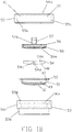
FIG. 1B is an exploded view of a tissue container utilized by the tissue specimen stage of the present invention having the window ofFIG. 1A and compression and clamp members receivable for applying pressure upon a tissue specimen against the window; -
FIG. 2 is a cross-sectional view of a planar window of the prior art rather than the window ofFIG. 1A with the same specimen asFIG. 1A to show the advantage of the window utilized by the stage of the present invention; -
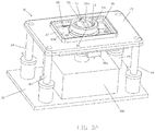
FIG. 3A is a perspective view of the stage of the present invention having the container ofFIG. 1B , the window ofFIG. 1A , and a microscope head situated below the carriage of the stage; -
FIG. 3B is the same perspective view ofFIG. 3A broken away to show the side of the movable carriage of the stage; -
FIG. 3C is a cross-sectional view of the stage ofFIG. 3A ; -
FIG. 3D is an exploded view of the carriage of the stage ofFIGS. 3A-C ; -
FIG. 3E is a bottom view of the stage ofFIG. 3A taken from below from the carriage with the microscope head removed; -
FIG. 4 is a bottom perspective view of the stage ofFIG. 3A with the microscope head and motors for driving the stage removed, and a coupler attachable to an x-y translation mechanism; -
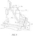
FIG. 5 is a perspective view of an x-y translation mechanism attachable to the coupler ofFIG. 4 ; -
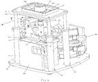
FIG. 6 is a perspective view showing the coupler ofFIG. 4 mounted to shafts extending from the x-y translation mechanism ofFIG. 5 for moving the carriage of the stage; and -
FIGS. 7A and7B are partial cross-sectional views similar toFIG. 3C showing two different rotational positions of the stage and window with respect to the objective lens in the case of a window having aspheric surface curvature rather than rotationally symmetric surface curvature as shown for example inFIG. 1A . - Referring to
FIG. 1A , an example of awindow 10 of the present invention is shown having asurface 12 with curvature approximating the shape of theedges tissue specimen 14 when located uponsurface 12. Preferablywindow 10 is rotationally circular symmetric along spherical orconcave surface 12. Thelower edge 14a andside edges 14b oftissue specimen 14face surface 12 ofwindow 10, which has a degree of curvature complementary toedges surface 12 as needed without require individual manual manipulation ofside edges 14b. If needed, pressure may be applied onto thetop edge 14c of the tissue specimen towardsurface 12, such as described below.Tissue specimen 14 and itsedges - Although the degree of curvature of the window is complementary to
edges surface 12 without require individual manual manipulation ofside edges 14b. Sometimes this contact does not entirely occur along all edges as desired. In this case, while alledges -
Window 10 is preferably movable along two rotational axes or dimensions so that different locations of thetissue specimen 14 are presentable to anobjective lens 30 as needed during imaging while maintaining the optical geometry shown inFIG. 1A as shown for example inFIG. 3C .Objective lens 30 is part of the optics of an optical sectioning microscope, such as a confocal microscope, OCT microscope or two-photon microscope such as described earlier. The movement of the window is enabled by astage 20 described later below. Motion of the window is controlled such that the window surface adjacent to the tissue is locally perpendicular to the optical axis of the objective lens. The distance between the window and the objective lens is adjusted so that the image of the section being captured is nominally at the window surface adjacent to the tissue specimen. - When it is desired to image inside the tissue an offset can be added to provide sectional imaging inside the tissue specimen. Since
window 10 is rotationally symmetric,arrow 11 may represent a first rotational axis or dimension, and rotating the window 90 degrees with respect to the plane of theFIG. 1A ,arrow 11 now illustrates the second rotational axis or dimension. Typically, the curvature of Mohs surgery tissue specimens are generally the same as the curvature ofsurface 12, andedges surface 12 when first applied (non-compressed) ontosurface 12. Such contact to surface 12 byedges compression member 54 applying uniform pressure uponupper edge 14c thetissue specimen 14 responsive to force applied by aclamp member 56 towardswindow 10 without damaging tissue edges 14a or 14b, as shown by the exploded view ofFIGS. 1B and3C .Window 10 is located at the bottom of atissue container 51 shown inFIG. 1B . -
Container 51 is a cylinder having an interior sized for receivingcompression member 54 and then clampmember 56. The container is received in aholder 50 so that the container'sflange 52 is received alongannular step 50e. The uppercylindrical portion 50c of theholder 50 is externally threaded so that aretainer 55 internally threaded alongwall 55a can screw ontoholder 50 to releasablylock clamp member 56 overcompression member 54 andwindow 10 whentissue specimen 14 is present uponwindow surface 12.Retainer 55 has a centralcircular opening 55b and two opposingtongues 61. To lockclamp member 56 tocontainer 51 andholder 50,clamp member 56 has aknob portion 57 and anannular lip 58 having two opposingslots 59. For purposes of illustration, only one slot is shown inFIG. 3A , and these slots are not shown inFIG. 1B . In operation,clamp member 56 is inserted intoretainer 50 in whichslots 59 align withtongues 61 so that the clamp member'sannular lip 58 is received along anannular step 60 ofcontainer 51. To engageclamp member 56 into a locking relationship withretainer 50,clamp member 56 is turned untilslots 59 andtongue 59 no longer align with each other, as shown for example inFIG. 3A and3B as will be described below. - Lower
cylindrical portion 50a ofholder 50 is mountable ontostage 20, as will be described in more detail below. Thus, a releasable locking mechanism is provided to retainclamp member 56 is such position during imaging by objective lens 30 (FIG. 1A ).Window 10 may be attached tocontainer 51 along the container's bottom wall or cover 49 having an opening 49a for receiving the window.Window 10 may be rigidly retained to cover 49, such as by adhesive. Thus,container 51 provides a tissue specimen receptacle having window 10 (or 10a as described later) withsubstantial surface 12 curvature adapted to at least approximate the surface curvature of an edge or edges of a non-histologicallyprepared tissue specimen 14 desired to be imaged by an optical sectioning microscope via the window when placed thereupon. The assembly of thecontainer 51 withcompression member 54 andclamp member 56 is best shown inFIG. 3C . -
Compression member 54 may be made of material which deforms in response to applied pressure, such as Styrofoam. Preferably, thebottom surface 56a ofclamp member 56, the top andbottom surfaces compression member 54, are of the same curvature as the curvature ofwindow surface 12 to facilitate applying uniform pressure towardswindow 10.Compression member 54 thus is located between the bottom ofclamp member 56 andwindow 10, such thatcompression member 54 gently compresses while applying pressure upon thetissue specimen 14 againstwindow 10. Thecompression member 54 may contact areas of the window around thetissue specimen 12. - The
window 10 of the present invention solves the problem with optical imaging of a tissue specimen for Mohs surgery in that the tissue specimen is generally thick, for example 2-3 mm, to enable optically imaging of all edges of interest along tissue edges 14a and 14b ifsuch tissue specimen 14 was present on a planar window rather thanwindow 10 of the present invention. For example,FIG. 2 shows an example of thesame tissue specimen 14 now on aplaner window 16, wheretissue edge 14b is non-planar and hence cannot contactsurface 17 ofwindow 16 by mere placement uponwindow 16. Even by applying pressure along thetop edge 14c towardswindow 16 does not readily enable the tissue edges 14b to being planar againstsurface 17 as needed for proper optical sectional imaging of the tissue specimen throughwindow 16 without additional manipulation of the tissue specimen as described earlier in connection withU.S. Patent No. 6,411,434 . This problem is avoided by providingwindow 10 with asurface curvature 12 following the expected shape of the edges of a tissue specimen of imaging interest. - Referring to
FIGS. 3A ,3B , and3C , astage 20 of the present invention is shown utilizingwindow 10 ofFIG. 1A .Stage 20 has a base member (or lower platform) 22 supporting an (upper)platform 23 upon fourposts 24.Post 24 may be an assembly of one or more shafts for attaching the four corners ofplatform 23 tobase 22 as illustrated.Platform 23 has arectangular opening 26 extending through acarriage mounting plate 23a attached underplatform 23 byscrews 23b. Extending fromplatform 23 about opening 26 is anoptional wall 27, as shown inFIG. 3A and in cross-section inFIGS. 3B and3D . Acarriage 28 is mounted for example toplatform 23, via mountingplate 23a, for movement along the two rotational axes described earlier that follow the radius of curvature ofsurface 12 ofwindow 10. In this manner, different locations alongwindow 10 are presentable toobjective lens 30 mounted for example in atube 30a belowcarriage 28. However other lens mounting mechanisms may be used. - Preferably,
objective lens 30 is part of the optics (or optical system) of aconfocal microscope head 30b attached tobase 22.Objective lens 30 may represent an assembly of lens or optical surfaces intube 30a, and is shown schematically inFIG. 3C as a single lens withintube 30a. The last optical surface oflens 30 is denoted at 30c. Theobjective lens 30 is preferably corrected for the base thickness ofwindow 10. The gap betweenwindow 10 and the lastoptical surface 30c ofobjective lens 30 intube 30a can be filled with an index matching liquid or gel, or may filled with air. The particular optics utilized in the objective lens assembly is selected in accordance with the optical material within the gap, the thickness of thewindow 10 and the curvature of thewindow 10 to enable optically corrected imaging of the specimen at or near the surface of the window. Optionally, a different objective lens may be utilized for the microscope if the curvature of the window is changed to accommodate different specimen curvatures.Confocal microscope head 30b is connected to a computer system (not shown) for providing optical sectional images at different depths intissue specimen 14 viawindow 12, which is transparent to the radiation wavelength(s) using in imaging by the microscope. Examples of confocal microscope heads and associated computer system and display are shown inU.S. Patent Nos. 5,788,639 and7,394,592 , which are incorporated herein by reference. For purposes of illustration,head 30b is shown byblock 30b.Head 30b may also be part of an imaging system for other types of optical sectioning microscopy, such as by two-photon, or optical coherence tomography, Raman microspectroscopy or confocal fluorescence microscopes. -
Carriage 28 comprises twocarriage members Carriage member 29a has arectangular opening 62 extending there through, whilecarriage member 29b has acircular opening 47 receivingtissue container 51 via aholder 50, as described below. -
Carriage member 29a has twofirst track members 33 attached in ledges along opposite ends 40a and 40b ofcarriage member 29a. Twosecond track members 35 are attached along opposite ends of rectangular mountingplate 23a, in which eachsecond track members 35 faces one offirst track members 33 ofcarriage member 29a.Carriage member 29b has twothird track members 42 attached along the underside of thecarriage member 29a along opposite ends thereof.Carriage member 29a has twofourth track members 44 each facing one ofthird track members 42 ofcarriage member 29b. Each of the two pairs of first and second track members, and two pairs of third and fourth track members, may for example, mated Gonio Way curved cross roller side assemblies, manufactured by Isotech, Inc, of Hatfield PA, USA. - To enable movement of the
carriage 28 in a first rotational axis,first track members 33 each have a track, groove, orchannel 34 curved following the curvature of thewindow 10 in the first rotational axis. Multiplerotational elements 36 partially extend from each ofsecond track members 35 intotrack 34 of thefirst track member 33 facing thesecond track member 35.Rotational elements 36 may be metal balls captured in pockets or openings alongsecond track member 35 enabling rotational mounting of such balls. Such pockets may be formed in asleeve 37 along each ofsecond track members 35. - To enable movement of the
carriage 28 in a second rotational axis,third track members 42 each have a track, groove, orchannel 43 curved following the curvature of thewindow 10 in the second rotational axis. Multiplerotational elements 45 partially extend from each offourth track members 44 intotrack 43 of thethird track member 42 facing thefourth track member 44.Rotational elements 45 may be metal balls captured in pockets or openings alongtrack member 44 enabling rotational mounting of such balls. Such pockets may be formed in asleeve 46 along each offourth track members 44. Although the rotational movement along two different rotational axes is shown using the illustrated track members, other mechanisms for movingcarriage members -
Circular opening 47 ofcarriage member 29b receivesholder 50 forspecimen container 51, as described earlier.Holder 50 is a cylinder with a lowercylindrical portion 50a and an uppercylindrical portion 50c. Lowercylindrical portion 50a has an outer diameter sized to be received incircular opening 47 so that anupper portion 50c extends away from opening 47, as best shown inFIGS. 1B and3C . Theholder 50 may have anouter flange 50b that lies along the top ofcarriage member 29b around opening 47, or 50b may be a ring clamp. To fixholder 50 tocarriage member 29b, opening 47 may have threads andholder 50 may screw intocarriage member 29b via a threaded outer lowercylindrical portion 50a. Alternatively,holder 50 may be fixed by other means, such a welded or adhesive. -
Upper portion 50c ofholder 50 has anopening 50d for receivingtissue container 51 so that anouter flange 52 ofcontainer 51 is located along an annular step about opening 50d ofupper portion 50c. Below itsflange 52,container 51 preferably has exterior threads which enablecontainer 51 to be tightened into threads along interior surface ofspecimen holder 50 viaopening 50d. This enablescontainer 51 to be easily inserted or removed fromstage 26, as needed, with or without a tissue specimen being clamped againstwindow 10 viacompression member 54. A fluid matched to the index of refraction of the tissue surfaces alongedges window surface 12 prior to placing the tissue specimen incontainer 51. A hole or bore 56b extends throughclamp member 56.Clamp member 56 is clamped byretainer 55 againstwindow 10 viacompression member 54. Air and/or liquid is allowed to escape, via a bore orhole 54c via its' concavemiddle opening 54d which communicates such and/or liquid via with bore orhole 56b ofclamp member 56 so as to not trap air bubbles with thetissue specimen 10 and give uneven compression. Also, the compression member's concavemiddle opening 54d provides a relief of pressure upon the middle of thetissue specimen 14 so that pressure is directed more towards tissue specimen edges 14b where it is needed more. -
Tube 30a withobjective lens 30 is disposed with respect tocarriage 28 to extend throughopenings respective carriage members cylindrical portion 50a ofholder 50 to viewtissue specimen 14 viawindow 10 whencontainer 51 is screwed intoholder 50.Objective lens 30 is directed towardwindow 10 being carried uponcarriage 28 alongoptical axis 31, as described earlier.Carriage 28 may be rotationally tilted following the curvature ofwindow surface 12, as shown for example inFIG. 3C (see angle betweenarrows 11a with respect to optical axis 31), so that any location of thetissue specimen 14 in contact withwindow surface 12 can be imaged viaobjective lens 30 while maintaining the same optical geometry. The distance or gap alongoptical axis 31 may be varied by the confocal microscope along a z axis, via a motor not shown, towards or away fromwindow 10 for focusing at different depths intissue specimen 14 uponwindow 10, as typical of a confocal microscope. A fluid matched to the index of refraction of the tissue surfaces 14a and 14b is preferably provided uponwindow surface 12 prior to imaging thetissue specimen 14 throughwindow 10. Selection of the index of refraction fluid may be as described inU.S. Patent No. 6,856,458 . - To drive motion of
carriage members window 10 to be in view ofobjective lens 30 and thus enables different parts of the tissue specimen onwindow 10 to be optimally sectioned by the microscope via its'lens 30. Twopiezoelectric motors Motor 38a is attached tocarriage member 29a having anactuator member 64 againstmember 35 so at to movecarriage member 29b with respect tocarriage member 29a along first rotational dimension.Motor 38b is attached tocarriage member 29a having an actuator member 66 againstmember 42 so at to movecarriage member 29a with respect tocarriage member 29b along the second rotational dimension. For example,piezoelectric motors actuator members 64 and 66, respectively, or a PILine® Ultrasonic Piezo Motor manufactured by OEM Motors, having a guide rod to provideactuator members 64 and 66, respectively. - Referring to
FIGS. 4 ,5 , and6 ,carriage 28 movement is enabled withoutmotors coupler 69 fixed tocarriage member 29a in which movement of the coupler along the x, y orthogonal axes correspond to orthogonal axes along withcarriage members Carriage members Coupler 68 has a socket into which is received a ball extending from anothercoupler 68 where the ball is rotatable in the socket, as typical of ball and socket rotational mounting.Coupler 68 has two mountingholes 70 extending there through. Alternatively,coupler 69 has a ball received into a socket ofcoupler 68. -
FIGS. 5 and6 shows a x-y translation mechanism orstage 72 having a plate 72a movable along the x-axis, and aplate 72b movable along the y axis, in whichplatform 23 andposts 24 are shown removed inFIG. 5 and present inFIG. 6 . Two linear guides and/or tracks 73a along the x axis enable movement of plate 72a along astationary support plate 71, while two linear guides and/or tracks 73b betweenplates 72a and 72b enable movement ofplate 72b with respect to plate 72a.Motors 77b drive plates 72a and 72b bidirectionally along their respective axes.Objective lens 30 withtube 30a extends frommicroscope head 30b through anopening 76 ofstage 72 and is fixed in position with respect to stage 72. Attached toplate 72b is astructure 75 having twovertical rods 74 which extend through twoholes 70 ofcoupler 68 as shown inFIG. 5 .Structure 75 is provided by twoflanges FIG. 5 ) extending from anplate 72b which are connected by a horizontal member 75c into whichvertical rods 74 are fixed. Movement of thex-y translation mechanism 72 along the x-axis in x direction effects movement ofcarriage member 29a and along the y-axis in y direction effects movement ofcarriage member 29a along their respective rotational axes as shows by arrows labeled X and Y inFIG. 6 .Coupler 68 is rotationally mounted so that it rotationally pivots with respect torods 74 as motion is applied bytranslation mechanism 72 via rods 74 (andcouplers 68 and 69) tostage 28.Electronics 30d of the microscope is also shown inFIG. 6 . -
Window 10 is rotationally movable, viacarriage 28 with respect toplatform 23, along two rotational axes utilizingpiezoelectric motors motors - Although a rotational symmetric
concave window 10 is shown providing a curved pocket for a tissue specimen 14 (see e.g.,FIG 1A ). window may have other curvatures each shaped for the particular curvature of tissue specimen edges of interest for pathological examination such as shown for example inFIGS. 7A and7B . -
FIGS. 7A and7B are similar toFIG. 3C , but have anaspheric window 10a shown in two different rotational positions ofcarriage 28 andwindow 10a with respect to theobjective lens 30. Unlike, rotationallysymmetric window 10 which has the same radius of curvature along its entire surface, or at least along the part thereof upon which thetissue specimen 14 is locatable,window 10a has an aspheric surface curvature, in which two or more regions or parts of the window may have different radius of curvature. In this example, there are two regions 9a and 9b, where region 9b is steeper than region 9a. The axes of rotation ofcarriage 28 correspond to radius of region 9b. In this manner, theaspheric window 10a adjusts for the stepper edges of atissue specimen 14 facing window region 9b, so that such edges readily lie againstwindow 10a when compressed, where such edges are steeper compared with the central area or edges of the tissue specimen. Region 9b being steeper so that theedge 14b climbs quicker aswindow 10a rotates up along region 9b ofwindow 10a, i.e., the radius ofwindow 10a reduces along region 9b from region 9a. The user can thus select one of multiple different windows with different surface curvatures (from symmetric to aspheric or different steeped region(s)) in accordance with the shape and size of the tissue cuts along the edges of interest when the tissue specimen is placed in the tissue container assembly ofFIG. 1B . - Upon the view of
objective lens 30 changing withwindow 10a motion between such regions, as in the case when thewindow 10a position changes from that ofFIG. 7A (see angle betweenarrows 11b) to that shown inFIG. 7B (see angle betweenarrows 11c), the optical geometry is adjusted accordingly, i.e., the distance between theobjective lens 30 and thewindow 10a is adjusted to maintain the same optical geometry between thewindow 10a and theobjective lens 30 so that focus is maintained aswindow 10a moves with respect toobjective lens 30. This may be achieved by movingobjective lens 30 towards or away fromwindow 10a alongoptical axis 31 as denotes byarrow 30d with window motion. Themicroscope head 30b has a motor which can move theentire tube 30a bidirectionally alongaxis 31 to maintain focus as regions change. Such movement is typical of focusing of optical sectioning microscopes. For example, in the case of a confocal microscope see earlier incorporated by referenceU.S. Patent No. 7,394,592 . Optionally, theentire platform 23 supportingwindow 10a, viacarriage 28, towards or away fromobjective lens 30 so as to maintain focus. To move the entire platform, posts 24 are each adjustable in height alongaxis 30d. Eachpost 24 may represents two cylinders in which the upper cylinder is slidable through the lower cylinder, and upper cylinder can be pneumatically or by a gear drive motor moved up and down under control of the microscope as needed to controlplatform 23 height. - Different windows may thus be selected for the shape of such edges desired to be imaged by the optical sectioning microscope. The aspheric (non-spherical) window is especially useful to account for the difference in thickness from the middle to the edge with the radius of curvature changing from the middle out. Other windows may also be used, such as spherical or approximately spherical window into which a general spherical tissue specimen is contained and rotated along two rotational axes to image edges against the window. Motion of the
non-spherical window 10a is controlled such that the window surface adjacent to the tissue specimen is locally perpendicular to the optical axis of theobjective lens 30. The distance between thewindow 10a and theobjective lens 30 is adjusted so that the image of the section being captured is nominally at the window surface adjacent to the tissue specimen. When it is desired to image inside the tissue specimen an offset can be added to provide sectional imaging inside the tissue specimen. - From the foregoing description, it will be apparent that a window having surface curvature adapted to the shape or surface curvature of the edges of a non-histologically prepared excised tissue specimen, and a stage and method for rotating such window with respect to an objective lens of an optical sectioning microscope have been provided. Variations and modifications in the herein described window, stage, and method in accordance with the invention will undoubtedly suggest themselves to those skilled in the art. Accordingly, the foregoing description should be taken as illustrative and not in a limiting sense.
Claims (12)
- A tissue specimen stage (20) for a microscope having an objective lens (30) for imaging tissue (14) through a window (10) comprising:said window (10) having a surface (12) with a curvature, being rotationally symmetric in two axes, upon which an excised tissue specimen (14) is locatablea carriage (28) to which said window (10) is mounted; anda platform (23) for supporting the carriage (28) and presenting said window (10) to the objective lens (30) of the microscope, wherein said carriage (28) is mounted to said platform (23) for movement along two rotational axes so that said carriage movement is adapted to follow the curvature of at least part of the window (10) while maintaining the optical geometry of the window (10) with respect to the objective lens (30).
- The tissue specimen stage (20) according to claim 1, wherein curvature of said surface (12) forms a pocket for receiving said tissue specimen (14).
- The tissue specimen stage (20) according to claim 1, further comprising means for moving said carriage (28) along said rotational axes.
- The tissue specimen stage (20) according to claim 1, further comprising a translation stage (72) moveable along two orthogonal axes which corresponds to said two rotational axes of said carriage (28), in which said translation stage (72) is mechanically coupled to said carriage (28) to enable movement of said translation stage (72) to move said carriage (28) along one or both of said rotational axes.
- The tissue specimen stage (20) according to claim 1, wherein said carriage (28) further comprises a first carriage member (29a) and a second carriage member (29b) in which each member (29a, 29b) is movable along one of said two rotational axes.
- The tissue specimen stage (20) according to claim 5, wherein said first carriage member (29a) is rotationally mounted to said platform (23) for movement along a first of said rotational axes with respect to the platform (23), and said second carriage (29b) member is rotationally mounted to said first carriage member (29a) for movement along the second of said rotational axes.
- The tissue specimen stage (20) according to claim 6, wherein said first carriage member (29a) is motor driven along a first of said rotational axes with respect to the platform (23), and said second carriage member (29b) is motor driven along the second of said rotational axes with respect to the first carriage member (29a).
- The tissue specimen stage (20) according to claim 7, further comprising a translation stage (72) moveable along two orthogonal axes which correspond to said two rotational axes, said translation stage (72) is mechanically coupled to said second carriage member (29b) to enable movement of one or both of said first and second carriage members (29a, 29b) along their respective rotational axes.
- A tissue specimen receptacle (51) comprising:
a window (10) having a first surface with substantial surface curvature, being rotationally symmetric in two axes adapted to at least approximate a portion of the surface (14a, 14b) of a non-histologically prepared tissue specimen (14) when placed thereupon in which the tissue specimen (14) is imageable through said rotationally symmetric window (10) by an optical sectioning microscope, comprising means (54) having a second surface opposite the first surface which follows the curvature of the first surface and a clamping means (56) for compressing said tissue specimen (14) against said rotationally symmetric window (10) when said tissue specimen (14) is present on said rotationally symmetric window (10). - The tissue specimen receptacle (51) according to claim 9, further comprising a wall (49) having an opening (49a) along which said window (10) is disposed.
- A method for presenting an excised tissue specimen (14) to an objective lens (30) of a microscope to be imaged through a window (10) comprising the steps of:rotating said window (10) having a surface (12) with a curvature, being rotationally symmetric in two axes upon which an excised tissue specimen (14) is locatable along two rotational axes following at least part of said rotationally symmetric curvature of said surface (12); andsupporting said window (10) with respect to an objective lens (30) of the microscope, in which said rotating step enables the optical geometry of the window to be maintained between said window (10) with respect to the objective lens (30).
- An apparatus for presenting an excised tissue specimen (14) to an objective lens (30) of a microscope comprising:a window (10) having a surface (12) with a curvature, being rotationally symmetric in two axes upon which an excised tissue specimen (14) is locatable; anda stage (20) for moving said window (10) along two orthogonal rotational axes to follow the rotationally symmetric curvature of at least part of the window (10) while maintaining the optical geometry of the window (10) with respect to the objective lens (30) wherein objective lens (30) is optically corrected to image excised tissue specimen (14) through window (10).
Applications Claiming Priority (2)
| Application Number | Priority Date | Filing Date | Title |
|---|---|---|---|
| US201261603364P | 2012-02-26 | 2012-02-26 | |
| PCT/US2013/027829 WO2013126928A1 (en) | 2012-02-26 | 2013-02-26 | Tissue specimen stage for an optical sectioning microscope |
Publications (3)
| Publication Number | Publication Date |
|---|---|
| EP2817609A1 EP2817609A1 (en) | 2014-12-31 |
| EP2817609A4 EP2817609A4 (en) | 2015-10-28 |
| EP2817609B1 true EP2817609B1 (en) | 2021-04-07 |
Family
ID=49002605
Family Applications (1)
| Application Number | Title | Priority Date | Filing Date |
|---|---|---|---|
| EP13751395.8A Active EP2817609B1 (en) | 2012-02-26 | 2013-02-26 | Tissue specimen stage for an optical sectioning microscope |
Country Status (6)
| Country | Link |
|---|---|
| US (1) | US9229210B2 (en) |
| EP (1) | EP2817609B1 (en) |
| CN (1) | CN104254767B (en) |
| AU (1) | AU2013222070B2 (en) |
| ES (1) | ES2878548T3 (en) |
| WO (1) | WO2013126928A1 (en) |
Families Citing this family (8)
| Publication number | Priority date | Publication date | Assignee | Title |
|---|---|---|---|---|
| WO2016126861A1 (en) * | 2015-02-04 | 2016-08-11 | Apollo Medical Optics Inc. | Optical coherence tomography apparatus and its application |
| US10839509B2 (en) | 2015-07-10 | 2020-11-17 | 3Scan Inc. | Spatial multiplexing of histological stains |
| US10514532B1 (en) | 2015-09-27 | 2019-12-24 | Caliber Imaging & Diagnostics, Inc. | Confocal microscope having a positionable imaging head mounted on a boom stand |
| WO2018089864A1 (en) | 2016-11-12 | 2018-05-17 | Caliber Imaging & Diagnostics, Inc. | Confocal microscope with positionable imaging head |
| DE102017214189A1 (en) * | 2017-08-15 | 2019-02-21 | Carl Zeiss Microscopy Gmbh | Method for operating a microscope assembly and a microscope assembly with a first microscope and at least one further microscope |
| CN112136071B (en) | 2018-02-26 | 2023-08-11 | 凯利博成像和诊断公司 | System and method for macroscopic and microscopic imaging of in vitro tissue |
| US20220187586A1 (en) * | 2019-04-18 | 2022-06-16 | The Administrators Of The Tulane Educational Fund | Systems and methods for sample positioning to facilitate microscopy |
| DE102021112720A1 (en) * | 2021-05-17 | 2022-11-17 | Physik Instrumente (PI) GmbH & Co KG | 2-dimensional movable linear or rotary table |
Citations (2)
| Publication number | Priority date | Publication date | Assignee | Title |
|---|---|---|---|---|
| US3220300A (en) * | 1961-06-09 | 1965-11-30 | California Inst Res Found | Specimen holder |
| US20120281208A1 (en) * | 2009-07-21 | 2012-11-08 | National University Corp. Okayama University | Chamber for optical observation, method for optically observing sample, and method for manufacturing lower transparent plate |
Family Cites Families (82)
| Publication number | Priority date | Publication date | Assignee | Title |
|---|---|---|---|---|
| US1002910A (en) | 1911-01-21 | 1911-09-12 | Foote Mineral Co | Display-mount. |
| US1991983A (en) | 1932-08-25 | 1935-02-19 | Joseph S Newman | Microscope slide |
| US2942520A (en) | 1955-12-20 | 1960-06-28 | George G Rose | Tissue culture device |
| US3202049A (en) | 1961-11-29 | 1965-08-24 | Bausch & Lomb | Liquid dispenser for microscope objective |
| US3510194A (en) | 1965-08-09 | 1970-05-05 | Robert F Connelly | Particle count membrane filter mount |
| DE1472294A1 (en) | 1966-09-07 | 1969-02-13 | Leitz Ernst Gmbh | Immersion body |
| GB1242527A (en) | 1967-10-20 | 1971-08-11 | Kodak Ltd | Optical instruments |
| US3556633A (en) | 1969-01-17 | 1971-01-19 | Winifred Liu Mutschmann | Specimen carrying slide with runoff trough |
| US3532412A (en) | 1969-01-17 | 1970-10-06 | Ibm | Package for and method of packaging pathology specimens |
| US3551023A (en) | 1969-01-17 | 1970-12-29 | Ibm | Pathology specimen processing method and article |
| US3736042A (en) | 1971-05-05 | 1973-05-29 | Clinical Sciences Inc | Microscope slide assembly |
| US3879106A (en) | 1973-04-11 | 1975-04-22 | Pelam Inc | Microscope slide cover slip |
| US3904781A (en) | 1973-10-15 | 1975-09-09 | Donald E Henry | Method of preparing cells for inspection |
| US4159875A (en) | 1976-10-21 | 1979-07-03 | Abbott Laboratories | Specimen holder |
| DE2655041C2 (en) | 1976-12-04 | 1982-04-15 | Fa. Carl Zeiss, 7920 Heidenheim | Immersion objective for use with several optically different immersion media |
| US4545831A (en) | 1982-09-13 | 1985-10-08 | The Mount Sinai School Of Medicine | Method for transferring a thin tissue section |
| DE3323742A1 (en) | 1983-07-01 | 1985-01-10 | Jürgen Dr. med. dent. 3008 Garbsen Kielmann | Macrodocumentation and experimentation chamber for hard tissue biopsies in medicine and biology |
| SE455736B (en) | 1984-03-15 | 1988-08-01 | Sarastro Ab | PROCEDURE KIT AND MICROPHOTOMETRATION AND ADDITIONAL IMAGE COMPOSITION |
| US4752347A (en) | 1986-10-03 | 1988-06-21 | Rada David C | Apparatus for preparing tissue sections |
| US4744643A (en) | 1987-01-20 | 1988-05-17 | Taylor Howard L | Apparatus for restricting motion of living microscopic organisms during observation under a microscope |
| CN87214469U (en) * | 1987-10-14 | 1988-07-20 | 上海钢铁研究所 | Multifunctional specimen-loading support for electronic scanning microscope |
| FR2626383B1 (en) | 1988-01-27 | 1991-10-25 | Commissariat Energie Atomique | EXTENDED FIELD SCAN AND DEPTH CONFOCAL OPTICAL MICROSCOPY AND DEVICES FOR CARRYING OUT THE METHOD |
| US4974952A (en) | 1988-03-31 | 1990-12-04 | Focht Daniel C | Live cell chamber for microscopes |
| US5257128A (en) | 1988-06-22 | 1993-10-26 | Board Of Regents, The University Of Texas System | Freezing/perfusion microscope stage |
| US5002735A (en) | 1988-07-12 | 1991-03-26 | Mark T. Alberhasky | Tissue analysis device |
| EP0393165B2 (en) | 1988-07-13 | 2007-07-25 | Optiscan Pty Ltd | Scanning confocal endoscope |
| US5073857A (en) | 1989-06-01 | 1991-12-17 | Accuron Corporation | Method and apparatus for cell analysis |
| US5034613A (en) | 1989-11-14 | 1991-07-23 | Cornell Research Foundation, Inc. | Two-photon laser microscopy |
| US5156150A (en) | 1990-06-08 | 1992-10-20 | Lary Banning G | Method of use of specimen apparatus |
| US5076680A (en) | 1990-07-05 | 1991-12-31 | Narong Arjarasumpun | Biological specimen holder for microscopic examination |
| DE4030699C1 (en) | 1990-09-28 | 1991-10-10 | Bruker Analytische Messtechnik Gmbh, 7512 Rheinstetten, De | |
| US5103338A (en) | 1990-10-04 | 1992-04-07 | Crowley Kevin D | Apparatus for positioning objects for microscopic examination |
| US5367401A (en) | 1990-11-23 | 1994-11-22 | Perceptive Scientific Instruments, Inc. | Microscope slide rotary stage |
| EP0501688A1 (en) | 1991-02-27 | 1992-09-02 | Hitachi, Ltd. | Apparatus and method for applying a laser beam through a microscope |
| US5719700A (en) | 1991-10-11 | 1998-02-17 | L'oreal | Apparatus for in vivo observation of the microscopic structure of the skin or of a similar tissue |
| US5311358A (en) | 1992-10-08 | 1994-05-10 | Time Surgical, Inc. | Universal microscope drape |
| US5889881A (en) | 1992-10-14 | 1999-03-30 | Oncometrics Imaging Corp. | Method and apparatus for automatically detecting malignancy-associated changes |
| GB2273994A (en) | 1992-12-18 | 1994-07-06 | Morphometrix Inc | Process microscopy system |
| US5364790A (en) | 1993-02-16 | 1994-11-15 | The Perkin-Elmer Corporation | In situ PCR amplification system |
| US5383472A (en) | 1993-07-22 | 1995-01-24 | Devlin; Mark T. | Method and apparatus for handling of biopsy tissue specimen |
| US5383234A (en) | 1993-09-03 | 1995-01-17 | Beekley Corporation | Radiographic system and a method for using the system for radiographic examination of tissue specimens |
| DE69423901T2 (en) | 1993-09-22 | 2000-10-26 | Pierce Chemical Co | DEVICE FOR DIALYZING SAMPLES |
| DE4423935C2 (en) | 1994-07-07 | 1998-02-05 | Deutsche Forsch Luft Raumfahrt | Cell for microscopic or macroscopic observation of a biological sample |
| US5554151A (en) | 1994-09-27 | 1996-09-10 | United States Surgical Corporation | Specimen retrieval container |
| US5880880A (en) | 1995-01-13 | 1999-03-09 | The General Hospital Corp. | Three-dimensional scanning confocal laser microscope |
| US5609827A (en) | 1995-05-02 | 1997-03-11 | Beekley Corporation | Biopsy specimen container |
| US5788639A (en) | 1995-07-13 | 1998-08-04 | Lucid Technologies, Inc. | Confocal imaging through thick dermal tissue |
| US7047064B1 (en) | 1995-07-13 | 2006-05-16 | Lucid, Inc. | Microscopic imaging apparatus and method |
| US5939251A (en) | 1996-07-12 | 1999-08-17 | Hu; Min | Apparatus and method for simplifying the processes in creating a sealed space on slides to conduct molecular biological reactions therein |
| US5870223A (en) | 1996-07-22 | 1999-02-09 | Nikon Corporation | Microscope system for liquid immersion observation |
| US6272235B1 (en) | 1997-03-03 | 2001-08-07 | Bacus Research Laboratories, Inc. | Method and apparatus for creating a virtual microscope slide |
| US6424852B1 (en) | 1996-10-18 | 2002-07-23 | Lucid, Inc. | System for confocal imaging within dermal tissue |
| US6745067B1 (en) | 1998-09-14 | 2004-06-01 | Lucid, Inc. | System for marking the locations of imaged tissue with respect to the surface of the tissue |
| US5836877A (en) | 1997-02-24 | 1998-11-17 | Lucid Inc | System for facilitating pathological examination of a lesion in tissue |
| JP4383545B2 (en) | 1997-03-19 | 2009-12-16 | ルーシド インコーポレーテッド | Cell surgery using confocal microscopy |
| US6100051A (en) * | 1997-06-27 | 2000-08-08 | The United States Of America As Represented By The Department Of Health And Human Services | Method utilizing convex geometry for laser capture microdissection |
| US5978695A (en) | 1997-08-18 | 1999-11-02 | Lucid Inc. | System for imaging mechanically stabilized tissue |
| US5812312A (en) | 1997-09-04 | 1998-09-22 | Lorincz; Andrew Endre | Microscope slide |
| US6134010A (en) | 1997-11-07 | 2000-10-17 | Lucid, Inc. | Imaging system using polarization effects to enhance image quality |
| US6048723A (en) | 1997-12-02 | 2000-04-11 | Flexcell International Corporation | Flexible bottom culture plate for applying mechanical load to cell cultures |
| EP1066488A1 (en) | 1998-02-26 | 2001-01-10 | Lucid, Inc. | Confocal microscope for facilitating cryosurgery of tissue |
| US6358475B1 (en) | 1998-05-27 | 2002-03-19 | Becton, Dickinson And Company | Device for preparing thin liquid for microscopic analysis |
| US6151127A (en) | 1998-05-28 | 2000-11-21 | The General Hospital Corporation | Confocal microscopy |
| US7227630B1 (en) | 1998-09-14 | 2007-06-05 | Lucid, Inc. | Imaging of surgical biopsies |
| JP2002524780A (en) | 1998-09-14 | 2002-08-06 | ルーシド インコーポレーテッド | Surgical biopsy imaging method |
| CA2345960A1 (en) | 1998-09-30 | 2000-04-06 | Trellis Bioinformatics, Inc. | High throughput microscopy |
| US6411434B1 (en) * | 1999-02-17 | 2002-06-25 | Lucid, Inc. | Cassette for facilitating optical sectioning of a retained tissue specimen |
| US6330106B1 (en) | 1999-02-17 | 2001-12-11 | Lucid, Inc. | Tissue specimen holder |
| US6720547B1 (en) | 1999-03-18 | 2004-04-13 | Lucid, Inc. | System and method for enhancing confocal reflectance images of tissue specimens |
| US6252705B1 (en) * | 1999-05-25 | 2001-06-26 | Schlumberger Technologies, Inc. | Stage for charged particle microscopy system |
| US7194118B1 (en) | 2000-11-10 | 2007-03-20 | Lucid, Inc. | System for optically sectioning and mapping surgically excised tissue |
| GB0219642D0 (en) | 2002-08-23 | 2002-10-02 | Gauthier Pierre | Method and device for preparing tissues sections |
| CN1791822A (en) | 2003-05-20 | 2006-06-21 | 卢西德有限公司 | Confocal microscope for imaging of selected locations of the body of a patient |
| US20090286305A1 (en) * | 2005-04-15 | 2009-11-19 | Wei-Sing Chu | Method for non-destructive macromolecule extraction from biological samples on slide |
| PL1937137T3 (en) * | 2005-09-29 | 2022-11-21 | General Hospital Corporation | Method and apparatus for optical imaging via spectral encoding |
| US7864996B2 (en) | 2006-02-17 | 2011-01-04 | Lucid, Inc. | System for macroscopic and confocal imaging of tissue |
| EP2115516B1 (en) | 2007-01-11 | 2012-04-11 | Renishaw PLC | A sample positioning stage and method of operation |
| EP2160590A4 (en) | 2007-05-18 | 2012-11-21 | Univ Vanderbilt | Improved interferometric detection system and method |
| US7869027B2 (en) * | 2009-04-20 | 2011-01-11 | Araca, Inc. | Confocal microscopy pad sample holder that measures displacement and method of using the same |
| CN201465986U (en) * | 2009-08-04 | 2010-05-12 | 山东理工大学 | Block-shaped metal material scanning electron microscope sample stable |
| WO2011094659A2 (en) | 2010-02-01 | 2011-08-04 | Clear-Cut Medical Ltd. | Tumor margin assessment of ex -vivo sample |
| CN201732097U (en) * | 2010-06-22 | 2011-02-02 | 山东建筑大学 | Sample stage with bending function for scanning electron microscope |
-
2013
- 2013-02-26 WO PCT/US2013/027829 patent/WO2013126928A1/en active Application Filing
- 2013-02-26 EP EP13751395.8A patent/EP2817609B1/en active Active
- 2013-02-26 AU AU2013222070A patent/AU2013222070B2/en active Active
- 2013-02-26 US US13/778,083 patent/US9229210B2/en active Active
- 2013-02-26 ES ES13751395T patent/ES2878548T3/en active Active
- 2013-02-26 CN CN201380019488.6A patent/CN104254767B/en active Active
Patent Citations (2)
| Publication number | Priority date | Publication date | Assignee | Title |
|---|---|---|---|---|
| US3220300A (en) * | 1961-06-09 | 1965-11-30 | California Inst Res Found | Specimen holder |
| US20120281208A1 (en) * | 2009-07-21 | 2012-11-08 | National University Corp. Okayama University | Chamber for optical observation, method for optically observing sample, and method for manufacturing lower transparent plate |
Also Published As
| Publication number | Publication date |
|---|---|
| EP2817609A1 (en) | 2014-12-31 |
| AU2013222070A1 (en) | 2014-09-18 |
| EP2817609A4 (en) | 2015-10-28 |
| BR112014020937A2 (en) | 2021-07-20 |
| CN104254767B (en) | 2016-10-26 |
| ES2878548T3 (en) | 2021-11-19 |
| WO2013126928A1 (en) | 2013-08-29 |
| US9229210B2 (en) | 2016-01-05 |
| AU2013222070B2 (en) | 2016-07-07 |
| CN104254767A (en) | 2014-12-31 |
| US20130222899A1 (en) | 2013-08-29 |
Similar Documents
| Publication | Publication Date | Title |
|---|---|---|
| EP2817609B1 (en) | Tissue specimen stage for an optical sectioning microscope | |
| US20230175969A1 (en) | Systems and methods for in-operating-theatre imaging of fresh tissue resected during surgery for pathology assessment | |
| US10409052B2 (en) | Inverted light-sheet microscope | |
| Abeytunge et al. | Confocal microscopy with strip mosaicing for rapid imaging over large areas of excised tissue | |
| US20110224574A1 (en) | Methods and systems for tissue processing and imaging | |
| US11156822B2 (en) | Selective plane illumination microscopy with multiple illumination units scanning an object in sync with a digital camera rolling shutter | |
| EP2883031B1 (en) | Devices applicable to tissue(s) which facilitates confocal microscopy, optical microscopy, spectroscopy and/or imaging | |
| KR101840081B1 (en) | Apparatus for preparing cytological specimens | |
| CN112136071A (en) | System and method for macroscopic and microscopic imaging of in vitro tissue | |
| BR112014020937B1 (en) | TISSUE SPECIMEN STAGE FOR A MICROSCOPE HAVING AN OBJECTIVE LENS TO PERFORM TISSUE IMAGING, TISSUE SPECIMEN RECEPTACLE, METHOD FOR PRESENTING AN EXCITED TISSUE SPECIMEN TO AN OBJECTIVE LENS FOR A MICROSCOPE TISSUE OBJECTIVE LENS OF A MICROSCOPE | |
| US11906720B1 (en) | Devices for ex vivo microscopic analysis of samples and in vivo microscopic analysis of the skin | |
| US20190227054A1 (en) | System, method and computer readable medium for microscopic imaging | |
| EP3553583A1 (en) | Selective plane illumination microscopy with multiple illumination units scanning an object in sync with a digital camera rolling shutter |
Legal Events
| Date | Code | Title | Description |
|---|---|---|---|
| PUAI | Public reference made under article 153(3) epc to a published international application that has entered the european phase |
Free format text: ORIGINAL CODE: 0009012 |
|
| 17P | Request for examination filed |
Effective date: 20140826 |
|
| AK | Designated contracting states |
Kind code of ref document: A1 Designated state(s): AL AT BE BG CH CY CZ DE DK EE ES FI FR GB GR HR HU IE IS IT LI LT LU LV MC MK MT NL NO PL PT RO RS SE SI SK SM TR |
|
| AX | Request for extension of the european patent |
Extension state: BA ME |
|
| DAX | Request for extension of the european patent (deleted) | ||
| RA4 | Supplementary search report drawn up and despatched (corrected) |
Effective date: 20150924 |
|
| RIC1 | Information provided on ipc code assigned before grant |
Ipc: G01N 21/00 20060101AFI20150918BHEP |
|
| STAA | Information on the status of an ep patent application or granted ep patent |
Free format text: STATUS: EXAMINATION IS IN PROGRESS |
|
| 17Q | First examination report despatched |
Effective date: 20191111 |
|
| STAA | Information on the status of an ep patent application or granted ep patent |
Free format text: STATUS: EXAMINATION IS IN PROGRESS |
|
| REG | Reference to a national code |
Ref country code: DE Ref legal event code: R079 Ref document number: 602013076739 Country of ref document: DE Free format text: PREVIOUS MAIN CLASS: G01N0021000000 Ipc: G02B0021260000 |
|
| RIC1 | Information provided on ipc code assigned before grant |
Ipc: G02B 21/26 20060101AFI20201228BHEP Ipc: G02B 21/34 20060101ALN20201228BHEP |
|
| GRAP | Despatch of communication of intention to grant a patent |
Free format text: ORIGINAL CODE: EPIDOSNIGR1 |
|
| STAA | Information on the status of an ep patent application or granted ep patent |
Free format text: STATUS: GRANT OF PATENT IS INTENDED |
|
| GRAS | Grant fee paid |
Free format text: ORIGINAL CODE: EPIDOSNIGR3 |
|
| GRAA | (expected) grant |
Free format text: ORIGINAL CODE: 0009210 |
|
| STAA | Information on the status of an ep patent application or granted ep patent |
Free format text: STATUS: THE PATENT HAS BEEN GRANTED |
|
| INTG | Intention to grant announced |
Effective date: 20210209 |
|
| AK | Designated contracting states |
Kind code of ref document: B1 Designated state(s): AL AT BE BG CH CY CZ DE DK EE ES FI FR GB GR HR HU IE IS IT LI LT LU LV MC MK MT NL NO PL PT RO RS SE SI SK SM TR |
|
| REG | Reference to a national code |
Ref country code: GB Ref legal event code: FG4D |
|
| REG | Reference to a national code |
Ref country code: AT Ref legal event code: REF Ref document number: 1380439 Country of ref document: AT Kind code of ref document: T Effective date: 20210415 Ref country code: CH Ref legal event code: EP |
|
| REG | Reference to a national code |
Ref country code: DE Ref legal event code: R096 Ref document number: 602013076739 Country of ref document: DE |
|
| REG | Reference to a national code |
Ref country code: IE Ref legal event code: FG4D |
|
| REG | Reference to a national code |
Ref country code: LT Ref legal event code: MG9D |
|
| REG | Reference to a national code |
Ref country code: NL Ref legal event code: MP Effective date: 20210407 Ref country code: AT Ref legal event code: MK05 Ref document number: 1380439 Country of ref document: AT Kind code of ref document: T Effective date: 20210407 |
|
| PG25 | Lapsed in a contracting state [announced via postgrant information from national office to epo] |
Ref country code: NL Free format text: LAPSE BECAUSE OF FAILURE TO SUBMIT A TRANSLATION OF THE DESCRIPTION OR TO PAY THE FEE WITHIN THE PRESCRIBED TIME-LIMIT Effective date: 20210407 Ref country code: LT Free format text: LAPSE BECAUSE OF FAILURE TO SUBMIT A TRANSLATION OF THE DESCRIPTION OR TO PAY THE FEE WITHIN THE PRESCRIBED TIME-LIMIT Effective date: 20210407 Ref country code: FI Free format text: LAPSE BECAUSE OF FAILURE TO SUBMIT A TRANSLATION OF THE DESCRIPTION OR TO PAY THE FEE WITHIN THE PRESCRIBED TIME-LIMIT Effective date: 20210407 Ref country code: HR Free format text: LAPSE BECAUSE OF FAILURE TO SUBMIT A TRANSLATION OF THE DESCRIPTION OR TO PAY THE FEE WITHIN THE PRESCRIBED TIME-LIMIT Effective date: 20210407 Ref country code: BG Free format text: LAPSE BECAUSE OF FAILURE TO SUBMIT A TRANSLATION OF THE DESCRIPTION OR TO PAY THE FEE WITHIN THE PRESCRIBED TIME-LIMIT Effective date: 20210707 Ref country code: AT Free format text: LAPSE BECAUSE OF FAILURE TO SUBMIT A TRANSLATION OF THE DESCRIPTION OR TO PAY THE FEE WITHIN THE PRESCRIBED TIME-LIMIT Effective date: 20210407 |
|
| REG | Reference to a national code |
Ref country code: ES Ref legal event code: FG2A Ref document number: 2878548 Country of ref document: ES Kind code of ref document: T3 Effective date: 20211119 |
|
| PG25 | Lapsed in a contracting state [announced via postgrant information from national office to epo] |
Ref country code: RS Free format text: LAPSE BECAUSE OF FAILURE TO SUBMIT A TRANSLATION OF THE DESCRIPTION OR TO PAY THE FEE WITHIN THE PRESCRIBED TIME-LIMIT Effective date: 20210407 Ref country code: SE Free format text: LAPSE BECAUSE OF FAILURE TO SUBMIT A TRANSLATION OF THE DESCRIPTION OR TO PAY THE FEE WITHIN THE PRESCRIBED TIME-LIMIT Effective date: 20210407 Ref country code: PL Free format text: LAPSE BECAUSE OF FAILURE TO SUBMIT A TRANSLATION OF THE DESCRIPTION OR TO PAY THE FEE WITHIN THE PRESCRIBED TIME-LIMIT Effective date: 20210407 Ref country code: NO Free format text: LAPSE BECAUSE OF FAILURE TO SUBMIT A TRANSLATION OF THE DESCRIPTION OR TO PAY THE FEE WITHIN THE PRESCRIBED TIME-LIMIT Effective date: 20210707 Ref country code: PT Free format text: LAPSE BECAUSE OF FAILURE TO SUBMIT A TRANSLATION OF THE DESCRIPTION OR TO PAY THE FEE WITHIN THE PRESCRIBED TIME-LIMIT Effective date: 20210809 Ref country code: LV Free format text: LAPSE BECAUSE OF FAILURE TO SUBMIT A TRANSLATION OF THE DESCRIPTION OR TO PAY THE FEE WITHIN THE PRESCRIBED TIME-LIMIT Effective date: 20210407 Ref country code: GR Free format text: LAPSE BECAUSE OF FAILURE TO SUBMIT A TRANSLATION OF THE DESCRIPTION OR TO PAY THE FEE WITHIN THE PRESCRIBED TIME-LIMIT Effective date: 20210708 Ref country code: IS Free format text: LAPSE BECAUSE OF FAILURE TO SUBMIT A TRANSLATION OF THE DESCRIPTION OR TO PAY THE FEE WITHIN THE PRESCRIBED TIME-LIMIT Effective date: 20210807 |
|
| REG | Reference to a national code |
Ref country code: DE Ref legal event code: R097 Ref document number: 602013076739 Country of ref document: DE |
|
| PG25 | Lapsed in a contracting state [announced via postgrant information from national office to epo] |
Ref country code: RO Free format text: LAPSE BECAUSE OF FAILURE TO SUBMIT A TRANSLATION OF THE DESCRIPTION OR TO PAY THE FEE WITHIN THE PRESCRIBED TIME-LIMIT Effective date: 20210407 Ref country code: CZ Free format text: LAPSE BECAUSE OF FAILURE TO SUBMIT A TRANSLATION OF THE DESCRIPTION OR TO PAY THE FEE WITHIN THE PRESCRIBED TIME-LIMIT Effective date: 20210407 Ref country code: EE Free format text: LAPSE BECAUSE OF FAILURE TO SUBMIT A TRANSLATION OF THE DESCRIPTION OR TO PAY THE FEE WITHIN THE PRESCRIBED TIME-LIMIT Effective date: 20210407 Ref country code: DK Free format text: LAPSE BECAUSE OF FAILURE TO SUBMIT A TRANSLATION OF THE DESCRIPTION OR TO PAY THE FEE WITHIN THE PRESCRIBED TIME-LIMIT Effective date: 20210407 Ref country code: SK Free format text: LAPSE BECAUSE OF FAILURE TO SUBMIT A TRANSLATION OF THE DESCRIPTION OR TO PAY THE FEE WITHIN THE PRESCRIBED TIME-LIMIT Effective date: 20210407 Ref country code: SM Free format text: LAPSE BECAUSE OF FAILURE TO SUBMIT A TRANSLATION OF THE DESCRIPTION OR TO PAY THE FEE WITHIN THE PRESCRIBED TIME-LIMIT Effective date: 20210407 |
|
| PLBE | No opposition filed within time limit |
Free format text: ORIGINAL CODE: 0009261 |
|
| STAA | Information on the status of an ep patent application or granted ep patent |
Free format text: STATUS: NO OPPOSITION FILED WITHIN TIME LIMIT |
|
| 26N | No opposition filed |
Effective date: 20220110 |
|
| PG25 | Lapsed in a contracting state [announced via postgrant information from national office to epo] |
Ref country code: IS Free format text: LAPSE BECAUSE OF FAILURE TO SUBMIT A TRANSLATION OF THE DESCRIPTION OR TO PAY THE FEE WITHIN THE PRESCRIBED TIME-LIMIT Effective date: 20210807 Ref country code: AL Free format text: LAPSE BECAUSE OF FAILURE TO SUBMIT A TRANSLATION OF THE DESCRIPTION OR TO PAY THE FEE WITHIN THE PRESCRIBED TIME-LIMIT Effective date: 20210407 |
|
| PG25 | Lapsed in a contracting state [announced via postgrant information from national office to epo] |
Ref country code: MC Free format text: LAPSE BECAUSE OF FAILURE TO SUBMIT A TRANSLATION OF THE DESCRIPTION OR TO PAY THE FEE WITHIN THE PRESCRIBED TIME-LIMIT Effective date: 20210407 |
|
| REG | Reference to a national code |
Ref country code: CH Ref legal event code: PL |
|
| REG | Reference to a national code |
Ref country code: BE Ref legal event code: MM Effective date: 20220228 |
|
| PG25 | Lapsed in a contracting state [announced via postgrant information from national office to epo] |
Ref country code: LU Free format text: LAPSE BECAUSE OF NON-PAYMENT OF DUE FEES Effective date: 20220226 |
|
| PG25 | Lapsed in a contracting state [announced via postgrant information from national office to epo] |
Ref country code: LI Free format text: LAPSE BECAUSE OF NON-PAYMENT OF DUE FEES Effective date: 20220228 Ref country code: IE Free format text: LAPSE BECAUSE OF NON-PAYMENT OF DUE FEES Effective date: 20220226 Ref country code: CH Free format text: LAPSE BECAUSE OF NON-PAYMENT OF DUE FEES Effective date: 20220228 |
|
| PG25 | Lapsed in a contracting state [announced via postgrant information from national office to epo] |
Ref country code: BE Free format text: LAPSE BECAUSE OF NON-PAYMENT OF DUE FEES Effective date: 20220228 |
|
| PGFP | Annual fee paid to national office [announced via postgrant information from national office to epo] |
Ref country code: FR Payment date: 20230227 Year of fee payment: 11 Ref country code: ES Payment date: 20230317 Year of fee payment: 11 |
|
| PGFP | Annual fee paid to national office [announced via postgrant information from national office to epo] |
Ref country code: GB Payment date: 20230222 Year of fee payment: 11 Ref country code: DE Payment date: 20230227 Year of fee payment: 11 |
|
| P01 | Opt-out of the competence of the unified patent court (upc) registered |
Effective date: 20230524 |
|
| PGFP | Annual fee paid to national office [announced via postgrant information from national office to epo] |
Ref country code: IT Payment date: 20230331 Year of fee payment: 11 |
|
| PG25 | Lapsed in a contracting state [announced via postgrant information from national office to epo] |
Ref country code: HU Free format text: LAPSE BECAUSE OF FAILURE TO SUBMIT A TRANSLATION OF THE DESCRIPTION OR TO PAY THE FEE WITHIN THE PRESCRIBED TIME-LIMIT; INVALID AB INITIO Effective date: 20130226 |