EP2816954B1 - Adaptive radiotherapy with spectral tissue of interest imaging and tracking - Google Patents
Adaptive radiotherapy with spectral tissue of interest imaging and tracking Download PDFInfo
- Publication number
- EP2816954B1 EP2816954B1 EP13716383.8A EP13716383A EP2816954B1 EP 2816954 B1 EP2816954 B1 EP 2816954B1 EP 13716383 A EP13716383 A EP 13716383A EP 2816954 B1 EP2816954 B1 EP 2816954B1
- Authority
- EP
- European Patent Office
- Prior art keywords
- interest
- tissue
- energy
- radiotherapy
- radiotherapy apparatus
- Prior art date
- Legal status (The legal status is an assumption and is not a legal conclusion. Google has not performed a legal analysis and makes no representation as to the accuracy of the status listed.)
- Active
Links
Images

Classifications
-
- A—HUMAN NECESSITIES
- A61—MEDICAL OR VETERINARY SCIENCE; HYGIENE
- A61N—ELECTROTHERAPY; MAGNETOTHERAPY; RADIATION THERAPY; ULTRASOUND THERAPY
- A61N5/00—Radiation therapy
- A61N5/10—X-ray therapy; Gamma-ray therapy; Particle-irradiation therapy
- A61N5/1048—Monitoring, verifying, controlling systems and methods
- A61N5/1064—Monitoring, verifying, controlling systems and methods for adjusting radiation treatment in response to monitoring
- A61N5/1065—Beam adjustment
-
- A—HUMAN NECESSITIES
- A61—MEDICAL OR VETERINARY SCIENCE; HYGIENE
- A61B—DIAGNOSIS; SURGERY; IDENTIFICATION
- A61B34/00—Computer-aided surgery; Manipulators or robots specially adapted for use in surgery
- A61B34/20—Surgical navigation systems; Devices for tracking or guiding surgical instruments, e.g. for frameless stereotaxis
-
- A—HUMAN NECESSITIES
- A61—MEDICAL OR VETERINARY SCIENCE; HYGIENE
- A61B—DIAGNOSIS; SURGERY; IDENTIFICATION
- A61B6/00—Apparatus for radiation diagnosis, e.g. combined with radiation therapy equipment
- A61B6/42—Apparatus for radiation diagnosis, e.g. combined with radiation therapy equipment with arrangements for detecting radiation specially adapted for radiation diagnosis
- A61B6/4208—Apparatus for radiation diagnosis, e.g. combined with radiation therapy equipment with arrangements for detecting radiation specially adapted for radiation diagnosis characterised by using a particular type of detector
- A61B6/4241—Apparatus for radiation diagnosis, e.g. combined with radiation therapy equipment with arrangements for detecting radiation specially adapted for radiation diagnosis characterised by using a particular type of detector using energy resolving detectors, e.g. photon counting
-
- A—HUMAN NECESSITIES
- A61—MEDICAL OR VETERINARY SCIENCE; HYGIENE
- A61B—DIAGNOSIS; SURGERY; IDENTIFICATION
- A61B6/00—Apparatus for radiation diagnosis, e.g. combined with radiation therapy equipment
- A61B6/48—Diagnostic techniques
- A61B6/481—Diagnostic techniques involving the use of contrast agents
-
- A—HUMAN NECESSITIES
- A61—MEDICAL OR VETERINARY SCIENCE; HYGIENE
- A61B—DIAGNOSIS; SURGERY; IDENTIFICATION
- A61B6/00—Apparatus for radiation diagnosis, e.g. combined with radiation therapy equipment
- A61B6/48—Diagnostic techniques
- A61B6/482—Diagnostic techniques involving multiple energy imaging
-
- A—HUMAN NECESSITIES
- A61—MEDICAL OR VETERINARY SCIENCE; HYGIENE
- A61N—ELECTROTHERAPY; MAGNETOTHERAPY; RADIATION THERAPY; ULTRASOUND THERAPY
- A61N5/00—Radiation therapy
- A61N5/10—X-ray therapy; Gamma-ray therapy; Particle-irradiation therapy
- A61N5/1048—Monitoring, verifying, controlling systems and methods
- A61N5/1064—Monitoring, verifying, controlling systems and methods for adjusting radiation treatment in response to monitoring
-
- G—PHYSICS
- G06—COMPUTING; CALCULATING OR COUNTING
- G06T—IMAGE DATA PROCESSING OR GENERATION, IN GENERAL
- G06T7/00—Image analysis
- G06T7/0002—Inspection of images, e.g. flaw detection
- G06T7/0012—Biomedical image inspection
-
- G—PHYSICS
- G06—COMPUTING; CALCULATING OR COUNTING
- G06T—IMAGE DATA PROCESSING OR GENERATION, IN GENERAL
- G06T7/00—Image analysis
- G06T7/70—Determining position or orientation of objects or cameras
- G06T7/73—Determining position or orientation of objects or cameras using feature-based methods
- G06T7/74—Determining position or orientation of objects or cameras using feature-based methods involving reference images or patches
-
- A—HUMAN NECESSITIES
- A61—MEDICAL OR VETERINARY SCIENCE; HYGIENE
- A61B—DIAGNOSIS; SURGERY; IDENTIFICATION
- A61B34/00—Computer-aided surgery; Manipulators or robots specially adapted for use in surgery
- A61B34/20—Surgical navigation systems; Devices for tracking or guiding surgical instruments, e.g. for frameless stereotaxis
- A61B2034/2046—Tracking techniques
- A61B2034/2065—Tracking using image or pattern recognition
-
- A—HUMAN NECESSITIES
- A61—MEDICAL OR VETERINARY SCIENCE; HYGIENE
- A61B—DIAGNOSIS; SURGERY; IDENTIFICATION
- A61B90/00—Instruments, implements or accessories specially adapted for surgery or diagnosis and not covered by any of the groups A61B1/00 - A61B50/00, e.g. for luxation treatment or for protecting wound edges
- A61B90/36—Image-producing devices or illumination devices not otherwise provided for
- A61B90/37—Surgical systems with images on a monitor during operation
- A61B2090/376—Surgical systems with images on a monitor during operation using X-rays, e.g. fluoroscopy
-
- A—HUMAN NECESSITIES
- A61—MEDICAL OR VETERINARY SCIENCE; HYGIENE
- A61B—DIAGNOSIS; SURGERY; IDENTIFICATION
- A61B90/00—Instruments, implements or accessories specially adapted for surgery or diagnosis and not covered by any of the groups A61B1/00 - A61B50/00, e.g. for luxation treatment or for protecting wound edges
- A61B90/39—Markers, e.g. radio-opaque or breast lesions markers
- A61B2090/3966—Radiopaque markers visible in an X-ray image
-
- A—HUMAN NECESSITIES
- A61—MEDICAL OR VETERINARY SCIENCE; HYGIENE
- A61B—DIAGNOSIS; SURGERY; IDENTIFICATION
- A61B34/00—Computer-aided surgery; Manipulators or robots specially adapted for use in surgery
- A61B34/10—Computer-aided planning, simulation or modelling of surgical operations
-
- A—HUMAN NECESSITIES
- A61—MEDICAL OR VETERINARY SCIENCE; HYGIENE
- A61B—DIAGNOSIS; SURGERY; IDENTIFICATION
- A61B6/00—Apparatus for radiation diagnosis, e.g. combined with radiation therapy equipment
- A61B6/42—Apparatus for radiation diagnosis, e.g. combined with radiation therapy equipment with arrangements for detecting radiation specially adapted for radiation diagnosis
- A61B6/4266—Apparatus for radiation diagnosis, e.g. combined with radiation therapy equipment with arrangements for detecting radiation specially adapted for radiation diagnosis characterised by using a plurality of detector units
-
- A—HUMAN NECESSITIES
- A61—MEDICAL OR VETERINARY SCIENCE; HYGIENE
- A61N—ELECTROTHERAPY; MAGNETOTHERAPY; RADIATION THERAPY; ULTRASOUND THERAPY
- A61N5/00—Radiation therapy
- A61N5/10—X-ray therapy; Gamma-ray therapy; Particle-irradiation therapy
- A61N5/1048—Monitoring, verifying, controlling systems and methods
- A61N5/1049—Monitoring, verifying, controlling systems and methods for verifying the position of the patient with respect to the radiation beam
- A61N2005/1061—Monitoring, verifying, controlling systems and methods for verifying the position of the patient with respect to the radiation beam using an x-ray imaging system having a separate imaging source
-
- A—HUMAN NECESSITIES
- A61—MEDICAL OR VETERINARY SCIENCE; HYGIENE
- A61N—ELECTROTHERAPY; MAGNETOTHERAPY; RADIATION THERAPY; ULTRASOUND THERAPY
- A61N5/00—Radiation therapy
- A61N5/10—X-ray therapy; Gamma-ray therapy; Particle-irradiation therapy
- A61N2005/1092—Details
- A61N2005/1098—Enhancing the effect of the particle by an injected agent or implanted device
-
- G—PHYSICS
- G06—COMPUTING; CALCULATING OR COUNTING
- G06T—IMAGE DATA PROCESSING OR GENERATION, IN GENERAL
- G06T2207/00—Indexing scheme for image analysis or image enhancement
- G06T2207/10—Image acquisition modality
- G06T2207/10116—X-ray image
- G06T2207/10128—Scintigraphy
-
- G—PHYSICS
- G06—COMPUTING; CALCULATING OR COUNTING
- G06T—IMAGE DATA PROCESSING OR GENERATION, IN GENERAL
- G06T2207/00—Indexing scheme for image analysis or image enhancement
- G06T2207/30—Subject of image; Context of image processing
- G06T2207/30004—Biomedical image processing
- G06T2207/30024—Cell structures in vitro; Tissue sections in vitro
Definitions
- the following generally relates adaptive radiotherapy and more particularly to an adaptive radiotherapy with spectral tissue of interest imaging and tracking.
- Radiotherapy also referred to as radiation oncology and radiation therapy
- Radiotherapy is a technique in which ionizing radiation is used to control or kill tissue of interest, such as tumor cells, and works by damaging the DNA of the cells of the tissue of interest.
- the patient typically receives a dose of ionizing radiation administered regularly (e.g. daily) over a period of time, for example, on the order of several weeks.
- a radiotherapy device generally referred to as a linear accelerator or a linac
- a radiotherapy device generally referred to as a linear accelerator or a linac
- the radiotherapy plan typically defines a beam shape and several angles of exposure that intersect at the tissue of interest, which results in an absorbed dose that is localized to the tissue of interest.
- a margin of tissue around the tissue of interest can been defined to allow for uncertainty in the treatment plan.
- a geometry e.g., size and/or shape
- a location of the tissue of interest in the patient may change within the patient. This can occur due to shrinkage of the tissue of interest, patient weight loss, internal organ movement (e.g., respiration), etc.
- the radiotherapy plan may no longer optimize treatment of the tissue of interest or mitigate damage to surrounding tissue.
- This has been compensated for through tumor tracking and adaptive radiotherapy planning in which the relative geometry and/or location changes of the tissue of interest in the patient after the radiotherapy plan is created and before a treatment or subsequent treatment is tracked and used to update the radiotherapy plan for a treatment session.
- Such tracking has be achieved using bi-planar or CT-based kilovolt (kV) and/or megavolt (MV) imaging of gold beads implanted in or close proximity to the tissue of interest.
- the patient is scanned and the relative geometry and the location of the tissue of interest is determined with respect to the gold beads in the resulting images.
- the radiotherapy plan can then be updated based on this information and the initial plan so that the treatment beam again is substantially localized only at the tissue of interest. Examples of such tracking are discussed in T. R. Mackie et al., "Tomotherapy: a new concept for the delivery of dynamic conformal radiotherapy," MEDICAL PHYSICS-LANCASTER PA, vol. 20, pp. 1709-1709, 1993 , P. J. Keall et al., "The management of respiratory motion in radiation oncology report of AAPM Task Group 76," Medical physics, vol. 33, p. 3874, 2006 , and R. D. Wiersma, W. Mao, and L. Xing, "Combined kV and MV imaging for real-time tracking of implanted fiducial markers," Medical Physics, vol. 35, no. 4, p. 1191, 2008 .
- a radiotherapy apparatus includes a tissue of interest tracker that receives a first image of tissue of interest and a second later acquired spectral image of the tissue of interest and tracks a change in a geometry and/or location of the tissue of interest based at least on the first and second images and generates a signal indicative of the change.
- the second later acquired spectral image is generated based on a first spectral signal corresponding to an output of an energy-resolving radiation sensitive detector array for a first predetermined energy range and a second spectral signal corresponding to an output of the energy-resolving radiation sensitive detector array for a second predetermined energy range.
- the second later acquired spectral image visually enhances scanned structure corresponding to the first or second signals while visually suppressing scanned structure corresponding to the other of the first or second signals.
- An adaptive planner updates a radiotherapy treatment plan based on the signal indicative of the change from the tissue of interest tracker.
- an imaging method for a radiotherapy system includes receiving imaging data from an energy-resolving radiation sensitive detector array of the radiotherapy system, obtaining a predetermined sub-energy range of interest, which is a sub-energy range of the acquired data energy range, selecting sub-imaging of the received imaging data corresponding to the obtained sub-energy range of interest, and generating a spectral image based on the selected sub-imaging data.
- a method in another aspect, includes obtaining a first image of tissue of interest, obtaining a second image of the tissue of interest, including a spectral composition of the tissue of interest, determining a changes in the tissue of interest between the first and second images, and updating a therapy plan based on the determined change to the tissue of interest.
- the invention may take form in various components and arrangements of components, and in various steps and arrangements of steps.
- the drawings are only for purposes of illustrating the preferred embodiments and are not to be construed as limiting the invention.
- spectral x-ray and/or spectral CT imaging capabilities of a radiotherapy apparatus are configured to image gold and/or other k-edge material doped nanoparticles (which are targeted to tissue of interest in a patient and optionally used enhance local dose to the cells of the tissue of interest during a radiotherapy session of the patient) to produce contrast enhanced spectral images of the tissue of interest.
- This may improve the contrast enhancement of the tissue of interest, relative to a configuration in which such spectral imaging capabilities are not present, which allows for improved tissue of interest tracking and targeting in adaptive radiotherapy without interventional marker bead implantation in the patient.
- FIGURES 1 and 2 schematically illustrate an example radiotherapy apparatus 100 that includes spectral imaging hardware and capabilities.
- FIGURE 1 schematically illustrates a side view of the example radiotherapy apparatus 100
- FIGURE 2 schematically illustrates a front view looking into the example radiotherapy apparatus 100 along line A-A of FIGURE 1 .
- the illustrated radiotherapy apparatus 100 includes a generally stationary portion 102 and a rotatable portion 104, which is rotatably supported by the generally stationary portion 102 and rotates about an examination region 106.
- the rotatable portion 104 is configured to rotate over a predetermined angular range or arc, such as two hundred degrees, or more or less than two hundred degrees.
- the radiotherapy apparatus 100 further includes a radiation source 108, such as a megavolt (MV) radiation source, which is supported by and rotates with the rotatable portion 104.
- the radiation source 108 is configured at least as a radiotherapy treatment source for radiotherapy apparatus 100.
- the radiation source 108 in connection with an optional two-dimensional (e.g., a flap panel) detector array 110, is also configured as an imaging source.
- the radiation source 108 is located opposite the detector array 110, across the examination region 106.
- the source 108 and the detector array 110 form a source/detector pair 108/110.
- the illustrated radiotherapy apparatus 100 also includes a radiation source 112, such as a kilovolt (kV) source.
- a radiation source 112 such as a kilovolt (kV) source.
- the radiation source 112 is supported by and rotates with the rotatable portion 104 about the examination region 106.
- the source 112 in connection with a two-dimensional (e.g., a flat panel) detector array 114, is configured as an imaging source.
- the radiation source 112, as shown is located opposite the detector array 114, across the examination region 106.
- the source 112 and the detector array 114 form a source/detector pair 112/114.
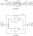
- the source/detector pair 108/110 and the source/detector pair 112/114 are angularly offset from each other by approximately ninety degrees, as shown in FIGURE 2 .
- the angularly offset may be different.
- the illustrated source/detector pair 112/114 includes an x-ray source/detector pair.
- the source/detector pair 112/114 alternatively or additionally includes a cone beam computed tomography (CT) source/detector pair.
- CT cone beam computed tomography
- the source 108 emits a treatment beam, which is directed at and irradiates tissue of interest (e.g., a tumor or other tissue of interest) of a patient on a subject support 116, which is used to position the patient in the examination region 106 for treatment and/or imaging.
- tissue of interest e.g., a tumor or other tissue of interest
- the source 108 can be rotated to one or more predetermined angular locations and/or the subject support 116 can be moved to facilitate directing the treatment beam according to the radiotherapy plan and/or user changes thereto.
- the source 108 For imaging with the source 108/detector pair 110, the source 108 emits radiation, while at one or more static positions or while moving along the arc, that traverses the patient in the examination region 106, and the detector array 110 detects the radiation that traverses the patient in the examination region 106 and generates an image indicative thereof.
- the image is a two dimensional projection image. Projection images acquired at different angular positions can be used to produce a three dimensional image.
- treatment and imaging using the source 108 can be performed serially or concurrently.
- the source 112 For imaging with the source/detector pair 112/114, the source 112 emits radiation, while at one or more static positions or while moving along the arc, that traverses the patient in the examination region 106, and the detector array 114 detects the radiation that traverses the patient in the examination region 106 and generates an image indicative thereof.
- the image is a two dimensional projection image. Projection images acquired at different angular positions can be used to produce a three dimensional image.
- At least one of the detectors 110 or 114 includes energy-resolving detector pixels, including scintillator-based multi-spectral detectors and/or direct conversion detector pixels (e.g., Si, Ge, GaAs, CdTe, CdZnTe, etc.).
- FIGURES 3 and 4 respectively illustrate non-limiting examples of scintillator-based multi-spectral detectors and FIGURES 5 and 6 illustrate a non-limiting example of direction conversion detector photon counting circuitry.
- the energy-resolving detector 300 includes a first layer 302 of scintillation material and a second layer 304 of scintillation material.
- the first and second layers 302 and 304 are coupled such that the first layer 302 is on a side 306 of the detector receiving incoming radiation.
- a photosensor 308 is coupled to a second opposing side of the detector 300 and includes photodiodes 310 and 312 facing the layers 302 and 304.
- Energy absorption generally, is dependent on the thickness thereof. As such, in this example, lower energy photons are absorbed in the first layer 302 and higher energy photons are absorbed in the second layer 304.
- the photodiodes 310 and 312 respectively have emission spectra that match the spectral sensitivities of the layers 302 and 304. As such, only the light emitted by the first layer 302 is absorbed by the photodiode 310, and only the light emitted by the second layer 304 is absorbed by the photodiode 312, and the photodiodes 310 and 311 respectively output signals indicative of radiation from different energy bands, which correspond to the first and second layers 302 and 304.
- FIGURE 4 shows a detector 400 in which the photosensor array 310 is coupled to a side 402 of the scintillator layers, which is perpendicular to the direction of incoming radiation. Other variations may include more scintillation layers / photosensors, and individual scintillation layers may have equal thickness (e.g., FIGURE 3 ) and/or different thickness (e.g., FIGURE 4 ).
- FIGURES 5 and 6 schematically illustrate non-limiting circuitry 500 for processing an output signal of a direct conversion energy-resolving detector (and/or a conventional integrating scintillator/photosensor detector).
- the output of such a detector includes an electrical current or voltage signals having a peak amplitude that is indicative of the energy of a detected photon.
- a pulse shaper 502 processes the signal and generates a pulse such as voltage or other pulse indicative of the energy of the detected photon. It is to be appreciated that the detector signal may be amplified and/or otherwise processed before being processed by the pulse shaper 702.
- An energy-discriminator 504 energy discriminates the pulse.
- the energy-discriminator 504 includes a comparator 506 that compares the amplitude of the pulse with two or more different energy thresholds, which correspond to different energies of interest.
- the comparator 506 produces an output signal indicative of the energy of the photon based on the comparison. This is shown in FIGURE 6 , where the comparator 506 includes N sub-comparators 602 1 , ..., 602 N , wherein N is an integer.
- Each of the sub-comparators 606 1 , ..., 606 N includes a first input, which receives the output of the pulse shaper 502 and a second input, which receives a threshold value TH 1 , ..., TH N , and the comparator 506 produces an output signal indicative of whether the amplitude of the incoming pulse exceeds the corresponding thresholds.
- a counter 508 increments a count value for each threshold based on the output of the energy discriminator 506. For instance, when the output of the comparator 506 for a particular threshold indicates that the amplitude of the pulse exceeds the corresponding threshold, the count value for that threshold is incremented.
- a binner 510 energy bins the signals and, hence, the photons into two or more energy bins based on the counts.
- An energy bin generally encompass an energy sub-range or window. For example, a bin may be defined for the energy range between two thresholds, where a photon resulting in a count for the lower threshold but not for higher threshold would be assigned to that bin.
- a general purpose computer serves as an operator console 118.
- the console 118 includes a human readable output device such as a monitor or display and an input device such as a keyboard and mouse.
- Software resident on the console 118 allows the operator to interact with the scanner 100 via a graphical user interface (GUI) or otherwise.
- GUI graphical user interface
- a processor of the console 118 executes the software, which is stored in computer readable storage medium, such as physical memory, of the console 118. Additionally or alternatively, some or all of the software can be stored on transitory medium such a carrier wave or signal.
- An injector 120 is configured to inject a contrast material(s), for example, for a contrast enhanced imaging procedure.
- the illustrated injector 120 is controlled by the console 118.
- the contrast agent is manually administered, and the injector 120 can be omitted.
- a suitable contrast material includes target specific (e.g., a tumor) nanoparitcles doped with gold, bismuth, gadolinium, etc. and/or other k-edge material. Nanoparticles doped with gold or other suitable material and targeted to specific cancer cells using dedicated antigens is discussed in R. Popovtzer et al., "Targeted Gold Nanoparticles enable Molecular CT Imaging of Cancer," Nano letters, vol. 8, no. 12, pp. 4593-4596, Dec. 2008 .
- tissue of interest tracking without implanted beads as the acquired data can be spectrally separated based on energy and images of the gold nanoparticles and, hence, substantially only the tissue of interest can be generated.
- nanoparticles may also allow for enhancing localized dose to the treated tumor, which may improve the efficacy of the radiotherapy treatment.
- Utilizing nanoparticles as such is discussed in R. I. Berbeco, W. Ngwa, and G. M. Makrigiorgos, "Localized Dose Enhancement to Tumor Blood Vessel Endothelial Cells via Megavoltage X-rays and Targeted Gold Nanoparticles: New Potential for External Beam Radiotherapy," International Journal of Radiation Oncology*Biology*Physics, vol. 81, no. 1, pp. 270-276, Sep. 2011 , and J. F. Hainfeld, F. A. Dilmanian, D. N. Slatkin, and H. M. Smilowitz, “Radiotherapy enhancement with gold nanoparticles,” Journal of Pharmacy and Pharmacology, vol. 60, no. 8, pp. 977-985, 2008 .
- a spectral processor 122 processes the signals from the energy-resolving detectors 110 and/or 114.
- the spectral processor 122 can generate an image with data corresponding to one of the different energy ranges or two or more (including all) of the different energy ranges. For example, where one energy range corresponds to a k-edge of a k-edge material dope to a nanoparticle attached to the tissue of interest, the spectral processor 122 can process only the data corresponding to the radiation having energy in the energy range of the k-edge material, thereby producing a spectral image in which the tissue of interest is visually enhanced and other tissue is visually suppressed.
- a tissue of interest (TOI) tracker 124 receives the spectral image of the tissue of interest (and/or other image) from the spectral processor 122 and tracks the geometry and/or location of the tissue of interest in the subject based at least on the spectral image of the tissue of interest and a previously acquired image. For example, the TOI tracker 124 may superimpose, combine, register, etc. the spectral image of the tissue of interest with the previous image, such as the initial planning image, an image after one or more treatments, an image before positioning the subject in the examination region 106, etc. The TOI tracker 124 visually presents the resulting data in a graphical user interface (GUI).
- GUI graphical user interface
- the TOI tracker 124 can, automatically without user interaction or with user interaction, determine any change in geometry and/or location of the tissue of interest.
- the TOI tracker 124 can generate a signal indicative of any change.
- the signal may include numerical values, a visual representation (e.g., displayed in the GUI), and/or other information. This can be performed for real-time and/or inter-fractional tracking.
- Known and/or other automatic and/or user interaction based segmentation approaches can be used to identify the geometry and/or location in the images, and known and/or other automatic and/or user interaction based measurement tools can be used to measure any change in geometry and/or location.
- An adaptive planner 126 updates, automatically and/or with user interaction, the treatment plan based on the signal from the TIO tracker 124.
- the update may include updating the position of the treatment source 108 and/or the subject support 116 to re-focus the treatment beam so that the treatment beam once again is substantially localized only at the tissue of interest.
- the adaptive planner 126 visually presents a proposed recommended update via a GUI, and the user accepts, modifies or rejects the update.
- the updated plan is provided to the console 118, which uses the plan to position the treatment source 108 and/or the subject support 116.
- the user uses the update plan to position the treatment source 108 and/or the subject support 116.
- the treatment plan can be created based on images acquired by the system 100 and/or other system such as a CT scanner, a magnetic resonance (MR) scanner, positron emission tomography (PET), etc.
- the radiotherapy apparatus 100 includes a single x-ray or CT source 112.
- the radiotherapy apparatus 100 includes two or more sources 112 and corresponding detectors 114, arranged at different angular locations with respect to each other in the x/y plane, where at least two of the radiation sources 112 emit radiation with different energy spectra.
- the at least two of the two or more radiation sources can be concurrently or individually employed during a same scan and different scans.
- At least one of the sources 110 or 112 is configured to switch between two or more emission voltages, for example, the source 112 can be configure to switch between 20 kVp to 140 kVp and/or other combination of kVps.
- a source controller or the like can switch the radiation source voltage from scan to scan, integration period to integration period, within an integration period, and/or otherwise. As a result, radiation beams having different mean emission energy spectra can be generated.
- one or more of the detector 110 or the source/detector pair 112/114 are omitted from the radiotherapy apparatus 110. Where either or both are omitted, a spectral imaging scanner separate from the radiotherapy apparatus 100 can be used for spectral imaging.
- FIGURE 7 illustrate an example method.
- a radiotherapy plan is obtained for a patient. This plan can be created using known and/or other approaches.
- a patient is positioned in the examination region 106 of the radiotherapy apparatus 100.
- the patient is scanned using at least one of the source/detector pairs 108/110 or 112/114.
- the acquired data is processed to produce a spectral image of a k-edge material of a nanoparticle attached to tissue of interest of the patient, wherein the spectral image visually enhances the k-edge material in the spectral image while visually suppressing other material in the spectral image.
- the spectral image is used to update the radiotherapy plan, including updating parameters that are based on the geometry and/or location of the tissue of interest in the patient, as described herein.
- the spectral image can be compared with a previously acquired image, and a geometry and/or location change in the tissue of interest, as determined between the two images, can be used to update the therapy plan.
- the updated radiotherapy plan can be used when employing the radiotherapy apparatus 100 to treat the tissue of interest.
- the nanoparticles may facilitate localizing dose enhancement to the tissue of interest during treatment of the tissue of interest using the radiotherapy apparatus 100.
- At least a portion of the above may be implemented by way of computer readable instructions, encoded or embedded on computer readable storage medium, which, when executed by a computer processor(s), cause the processor(s) to carry out the described acts. Additionally or alternatively, at least one of the computer readable instructions is carried by a signal, carrier wave or other transitory medium.
Description
- The following generally relates adaptive radiotherapy and more particularly to an adaptive radiotherapy with spectral tissue of interest imaging and tracking.
- Radiotherapy (also referred to as radiation oncology and radiation therapy) is a technique in which ionizing radiation is used to control or kill tissue of interest, such as tumor cells, and works by damaging the DNA of the cells of the tissue of interest. With radiotherapy, the patient typically receives a dose of ionizing radiation administered regularly (e.g. daily) over a period of time, for example, on the order of several weeks. During a treatment session, the patient is positioned in an examination region of a radiotherapy device (generally referred to as a linear accelerator or a linac), which is used to irradiate the tumor. To spare surrounding tissue, the radiotherapy plan typically defines a beam shape and several angles of exposure that intersect at the tissue of interest, which results in an absorbed dose that is localized to the tissue of interest. A margin of tissue around the tissue of interest can been defined to allow for uncertainty in the treatment plan.
- Over the course of the treatment sessions, a geometry (e.g., size and/or shape) of the tissue of interest and/or a location of the tissue of interest in the patient may change within the patient. This can occur due to shrinkage of the tissue of interest, patient weight loss, internal organ movement (e.g., respiration), etc. As a consequence, the radiotherapy plan may no longer optimize treatment of the tissue of interest or mitigate damage to surrounding tissue. This has been compensated for through tumor tracking and adaptive radiotherapy planning in which the relative geometry and/or location changes of the tissue of interest in the patient after the radiotherapy plan is created and before a treatment or subsequent treatment is tracked and used to update the radiotherapy plan for a treatment session. Such tracking has be achieved using bi-planar or CT-based kilovolt (kV) and/or megavolt (MV) imaging of gold beads implanted in or close proximity to the tissue of interest.
- For tissue of interest tracking, the patient is scanned and the relative geometry and the location of the tissue of interest is determined with respect to the gold beads in the resulting images. The radiotherapy plan can then be updated based on this information and the initial plan so that the treatment beam again is substantially localized only at the tissue of interest. Examples of such tracking are discussed in T. R. Mackie et al., "Tomotherapy: a new concept for the delivery of dynamic conformal radiotherapy," MEDICAL PHYSICS-LANCASTER PA, vol. 20, pp. 1709-1709, 1993, P. J. Keall et al., "The management of respiratory motion in radiation oncology report of AAPM Task Group 76," Medical physics, vol. 33, p. 3874, 2006, and R. D. Wiersma, W. Mao, and L. Xing, "Combined kV and MV imaging for real-time tracking of implanted fiducial markers," Medical Physics, vol. 35, no. 4, p. 1191, 2008.
- Unfortunately, implanting such beads in or close to the tissue of interest in the patient is an invasive procedure and can be a challenging task. In view of at least the above, there is an unresolved need for one or more other approaches to tissue of interest tracking and updating a radiotherapy plan based thereon in adaptive radiotherapy.
- Aspects described herein address the above-referenced problems and others.
- In one aspect, a radiotherapy apparatus includes a tissue of interest tracker that receives a first image of tissue of interest and a second later acquired spectral image of the tissue of interest and tracks a change in a geometry and/or location of the tissue of interest based at least on the first and second images and generates a signal indicative of the change. The second later acquired spectral image is generated based on a first spectral signal corresponding to an output of an energy-resolving radiation sensitive detector array for a first predetermined energy range and a second spectral signal corresponding to an output of the energy-resolving radiation sensitive detector array for a second predetermined energy range. The second later acquired spectral image visually enhances scanned structure corresponding to the first or second signals while visually suppressing scanned structure corresponding to the other of the first or second signals. An adaptive planner updates a radiotherapy treatment plan based on the signal indicative of the change from the tissue of interest tracker.
- In another aspect, an imaging method for a radiotherapy system includes receiving imaging data from an energy-resolving radiation sensitive detector array of the radiotherapy system, obtaining a predetermined sub-energy range of interest, which is a sub-energy range of the acquired data energy range, selecting sub-imaging of the received imaging data corresponding to the obtained sub-energy range of interest, and generating a spectral image based on the selected sub-imaging data.
- In another aspect, a method includes obtaining a first image of tissue of interest, obtaining a second image of the tissue of interest, including a spectral composition of the tissue of interest, determining a changes in the tissue of interest between the first and second images, and updating a therapy plan based on the determined change to the tissue of interest.
- The invention may take form in various components and arrangements of components, and in various steps and arrangements of steps. The drawings are only for purposes of illustrating the preferred embodiments and are not to be construed as limiting the invention.
-
FIGURE 1 schematically illustrates a side view of an example radiotherapy system that includes energy-resolving radiation sensitive detectors. -
FIGURE 2 schematically illustrates a front view looking into the example radiotherapy system ofFIGURE 1 along line A-A. -
FIGURE 3 schematically illustrates an example scintillator / back mounted photosensor energy-resolving radiation sensitive detector. -
FIGURE 4 schematically illustrates an example scintillator / side mounted photosensor energy-resolving radiation sensitive detector. -
FIGURE 5 schematically illustrates direct conversion energy-resolving circuitry for a direct conversion detector of the example radiotherapy system ofFIGURE 1 . -
FIGURE 6 schematically illustrates an example comparator of the discriminator of the energy-resolving circuitry ofFIGURE 5 . -
FIGURE 7 illustrates an example method. - The following describes an adaptive radiotherapy approach in which spectral x-ray and/or spectral CT imaging capabilities of a radiotherapy apparatus are configured to image gold and/or other k-edge material doped nanoparticles (which are targeted to tissue of interest in a patient and optionally used enhance local dose to the cells of the tissue of interest during a radiotherapy session of the patient) to produce contrast enhanced spectral images of the tissue of interest. This may improve the contrast enhancement of the tissue of interest, relative to a configuration in which such spectral imaging capabilities are not present, which allows for improved tissue of interest tracking and targeting in adaptive radiotherapy without interventional marker bead implantation in the patient.
-
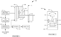
FIGURES 1 and 2 schematically illustrate anexample radiotherapy apparatus 100 that includes spectral imaging hardware and capabilities.FIGURE 1 schematically illustrates a side view of theexample radiotherapy apparatus 100, andFIGURE 2 schematically illustrates a front view looking into theexample radiotherapy apparatus 100 along line A-A ofFIGURE 1 . - The illustrated
radiotherapy apparatus 100 includes a generallystationary portion 102 and arotatable portion 104, which is rotatably supported by the generallystationary portion 102 and rotates about anexamination region 106. Therotatable portion 104 is configured to rotate over a predetermined angular range or arc, such as two hundred degrees, or more or less than two hundred degrees. - The
radiotherapy apparatus 100 further includes aradiation source 108, such as a megavolt (MV) radiation source, which is supported by and rotates with therotatable portion 104. In this example, theradiation source 108 is configured at least as a radiotherapy treatment source forradiotherapy apparatus 100. Optionally, theradiation source 108, in connection with an optional two-dimensional (e.g., a flap panel)detector array 110, is also configured as an imaging source. Theradiation source 108, as shown, is located opposite thedetector array 110, across theexamination region 106. Thesource 108 and thedetector array 110 form a source/detector pair 108/110. - The illustrated
radiotherapy apparatus 100 also includes aradiation source 112, such as a kilovolt (kV) source. Likewise, theradiation source 112 is supported by and rotates with therotatable portion 104 about theexamination region 106. In this example, thesource 112, in connection with a two-dimensional (e.g., a flat panel)detector array 114, is configured as an imaging source. Likewise, theradiation source 112, as shown, is located opposite thedetector array 114, across theexamination region 106. Thesource 112 and thedetector array 114 form a source/detector pair 112/114. - In the illustrated embodiment, the source/
detector pair 108/110 and the source/detector pair 112/114 are angularly offset from each other by approximately ninety degrees, as shown inFIGURE 2 . However, in other embodiments, the angularly offset may be different. Furthermore, the illustrated source/detector pair 112/114 includes an x-ray source/detector pair. However, in another embodiment, the source/detector pair 112/114 alternatively or additionally includes a cone beam computed tomography (CT) source/detector pair. - Generally, for radiotherapy treatment, the
source 108 emits a treatment beam, which is directed at and irradiates tissue of interest (e.g., a tumor or other tissue of interest) of a patient on asubject support 116, which is used to position the patient in theexamination region 106 for treatment and/or imaging. Thesource 108 can be rotated to one or more predetermined angular locations and/or thesubject support 116 can be moved to facilitate directing the treatment beam according to the radiotherapy plan and/or user changes thereto. - For imaging with the
source 108/detector pair 110, thesource 108 emits radiation, while at one or more static positions or while moving along the arc, that traverses the patient in theexamination region 106, and thedetector array 110 detects the radiation that traverses the patient in theexamination region 106 and generates an image indicative thereof. At a static position, the image is a two dimensional projection image. Projection images acquired at different angular positions can be used to produce a three dimensional image. - It is to be appreciated that treatment and imaging using the
source 108 can be performed serially or concurrently. - For imaging with the source/
detector pair 112/114, thesource 112 emits radiation, while at one or more static positions or while moving along the arc, that traverses the patient in theexamination region 106, and thedetector array 114 detects the radiation that traverses the patient in theexamination region 106 and generates an image indicative thereof. At a static position, the image is a two dimensional projection image. Projection images acquired at different angular positions can be used to produce a three dimensional image. - In the illustrated embodiment, at least one of the
detectors FIGURES 3 and 4 respectively illustrate non-limiting examples of scintillator-based multi-spectral detectors andFIGURES 5 and 6 illustrate a non-limiting example of direction conversion detector photon counting circuitry. - Turning briefly to
FIGURE 3 , the energy-resolvingdetector 300 includes afirst layer 302 of scintillation material and asecond layer 304 of scintillation material. The first andsecond layers first layer 302 is on aside 306 of the detector receiving incoming radiation. Aphotosensor 308 is coupled to a second opposing side of thedetector 300 and includesphotodiodes layers first layer 302 and higher energy photons are absorbed in thesecond layer 304. - The
photodiodes layers first layer 302 is absorbed by thephotodiode 310, and only the light emitted by thesecond layer 304 is absorbed by thephotodiode 312, and thephotodiodes 310 and 311 respectively output signals indicative of radiation from different energy bands, which correspond to the first andsecond layers FIGURE 4 shows adetector 400 in which thephotosensor array 310 is coupled to aside 402 of the scintillator layers, which is perpendicular to the direction of incoming radiation. Other variations may include more scintillation layers / photosensors, and individual scintillation layers may have equal thickness (e.g.,FIGURE 3 ) and/or different thickness (e.g.,FIGURE 4 ). -
FIGURES 5 and 6 schematically illustratenon-limiting circuitry 500 for processing an output signal of a direct conversion energy-resolving detector (and/or a conventional integrating scintillator/photosensor detector). Generally, the output of such a detector includes an electrical current or voltage signals having a peak amplitude that is indicative of the energy of a detected photon. Apulse shaper 502 processes the signal and generates a pulse such as voltage or other pulse indicative of the energy of the detected photon. It is to be appreciated that the detector signal may be amplified and/or otherwise processed before being processed by thepulse shaper 702. - An energy-
discriminator 504 energy discriminates the pulse. In the illustrated example, the energy-discriminator 504 includes acomparator 506 that compares the amplitude of the pulse with two or more different energy thresholds, which correspond to different energies of interest. Thecomparator 506 produces an output signal indicative of the energy of the photon based on the comparison. This is shown inFIGURE 6 , where thecomparator 506 includes N sub-comparators 6021, ..., 602N, wherein N is an integer. Each of the sub-comparators 6061, ..., 606N includes a first input, which receives the output of thepulse shaper 502 and a second input, which receives a threshold value TH1, ..., THN, and thecomparator 506 produces an output signal indicative of whether the amplitude of the incoming pulse exceeds the corresponding thresholds. - Returning to
FIGURE 5 , acounter 508 increments a count value for each threshold based on the output of theenergy discriminator 506. For instance, when the output of thecomparator 506 for a particular threshold indicates that the amplitude of the pulse exceeds the corresponding threshold, the count value for that threshold is incremented. Abinner 510 energy bins the signals and, hence, the photons into two or more energy bins based on the counts. An energy bin generally encompass an energy sub-range or window. For example, a bin may be defined for the energy range between two thresholds, where a photon resulting in a count for the lower threshold but not for higher threshold would be assigned to that bin. - Returning to
FIGURES 1 and 2 , a general purpose computer serves as anoperator console 118. Theconsole 118 includes a human readable output device such as a monitor or display and an input device such as a keyboard and mouse. Software resident on theconsole 118 allows the operator to interact with thescanner 100 via a graphical user interface (GUI) or otherwise. A processor of theconsole 118 executes the software, which is stored in computer readable storage medium, such as physical memory, of theconsole 118. Additionally or alternatively, some or all of the software can be stored on transitory medium such a carrier wave or signal. - An
injector 120 is configured to inject a contrast material(s), for example, for a contrast enhanced imaging procedure. The illustratedinjector 120 is controlled by theconsole 118. However, in an alternative embodiment, the contrast agent is manually administered, and theinjector 120 can be omitted. A suitable contrast material includes target specific (e.g., a tumor) nanoparitcles doped with gold, bismuth, gadolinium, etc. and/or other k-edge material. Nanoparticles doped with gold or other suitable material and targeted to specific cancer cells using dedicated antigens is discussed in R. Popovtzer et al., "Targeted Gold Nanoparticles enable Molecular CT Imaging of Cancer," Nano letters, vol. 8, no. 12, pp. 4593-4596, Dec. 2008. - Contrast materials with gold or other k-edge materials are discussed in D. P. Cormode et al., "Atherosclerotic Plaque Composition: Analysis with Multicolor CT and Targeted Gold Nanoparticles1," Radiology, vol. 256, no. 3, pp. 774 -782, 2010 and Pan, D. (2010). Computed Tomography in Color: NanoK-Enhanced Spectral CT Molecular imaging. Angewandte Chemie, 9635-9. Using such a contrast material along with the energy-resolving detectors (
detectors 110 and/or 114) allows for tissue of interest tracking without implanted beads as the acquired data can be spectrally separated based on energy and images of the gold nanoparticles and, hence, substantially only the tissue of interest can be generated. - Moreover, gold doped nanoparticles may also allow for enhancing localized dose to the treated tumor, which may improve the efficacy of the radiotherapy treatment. Utilizing nanoparticles as such is discussed in R. I. Berbeco, W. Ngwa, and G. M. Makrigiorgos, "Localized Dose Enhancement to Tumor Blood Vessel Endothelial Cells via Megavoltage X-rays and Targeted Gold Nanoparticles: New Potential for External Beam Radiotherapy," International Journal of Radiation Oncology*Biology*Physics, vol. 81, no. 1, pp. 270-276, Sep. 2011, and J. F. Hainfeld, F. A. Dilmanian, D. N. Slatkin, and H. M. Smilowitz, "Radiotherapy enhancement with gold nanoparticles," Journal of Pharmacy and Pharmacology, vol. 60, no. 8, pp. 977-985, 2008.
- A
spectral processor 122 processes the signals from the energy-resolvingdetectors 110 and/or 114. Thespectral processor 122 can generate an image with data corresponding to one of the different energy ranges or two or more (including all) of the different energy ranges. For example, where one energy range corresponds to a k-edge of a k-edge material dope to a nanoparticle attached to the tissue of interest, thespectral processor 122 can process only the data corresponding to the radiation having energy in the energy range of the k-edge material, thereby producing a spectral image in which the tissue of interest is visually enhanced and other tissue is visually suppressed. - A tissue of interest (TOI)
tracker 124 receives the spectral image of the tissue of interest (and/or other image) from thespectral processor 122 and tracks the geometry and/or location of the tissue of interest in the subject based at least on the spectral image of the tissue of interest and a previously acquired image. For example, theTOI tracker 124 may superimpose, combine, register, etc. the spectral image of the tissue of interest with the previous image, such as the initial planning image, an image after one or more treatments, an image before positioning the subject in theexamination region 106, etc. TheTOI tracker 124 visually presents the resulting data in a graphical user interface (GUI). - The
TOI tracker 124 can, automatically without user interaction or with user interaction, determine any change in geometry and/or location of the tissue of interest. TheTOI tracker 124 can generate a signal indicative of any change. The signal may include numerical values, a visual representation (e.g., displayed in the GUI), and/or other information. This can be performed for real-time and/or inter-fractional tracking. Known and/or other automatic and/or user interaction based segmentation approaches can be used to identify the geometry and/or location in the images, and known and/or other automatic and/or user interaction based measurement tools can be used to measure any change in geometry and/or location. - An
adaptive planner 126 updates, automatically and/or with user interaction, the treatment plan based on the signal from theTIO tracker 124. The update may include updating the position of thetreatment source 108 and/or thesubject support 116 to re-focus the treatment beam so that the treatment beam once again is substantially localized only at the tissue of interest. With user interaction updates, theadaptive planner 126 visually presents a proposed recommended update via a GUI, and the user accepts, modifies or rejects the update. - The updated plan is provided to the
console 118, which uses the plan to position thetreatment source 108 and/or thesubject support 116. Alternatively, the user uses the update plan to position thetreatment source 108 and/or thesubject support 116. The treatment plan can be created based on images acquired by thesystem 100 and/or other system such as a CT scanner, a magnetic resonance (MR) scanner, positron emission tomography (PET), etc. - Variations are contemplated.
- In the illustrated embodiment, the
radiotherapy apparatus 100 includes a single x-ray orCT source 112. In another embodiment, theradiotherapy apparatus 100 includes two ormore sources 112 andcorresponding detectors 114, arranged at different angular locations with respect to each other in the x/y plane, where at least two of theradiation sources 112 emit radiation with different energy spectra. The at least two of the two or more radiation sources can be concurrently or individually employed during a same scan and different scans. - Additionally or alternatively, at least one of the
sources source 112 can be configure to switch between 20 kVp to 140 kVp and/or other combination of kVps. A source controller or the like can switch the radiation source voltage from scan to scan, integration period to integration period, within an integration period, and/or otherwise. As a result, radiation beams having different mean emission energy spectra can be generated. - In another embodiment, one or more of the
detector 110 or the source/detector pair 112/114 are omitted from theradiotherapy apparatus 110. Where either or both are omitted, a spectral imaging scanner separate from theradiotherapy apparatus 100 can be used for spectral imaging. -
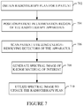
FIGURE 7 illustrate an example method. - It is to be appreciated that the ordering of the acts in the methods described herein is not limiting. As such, other orderings are contemplated herein. In addition, one or more acts may be omitted and/or one or more additional acts may be included.
- At 702, a radiotherapy plan is obtained for a patient. This plan can be created using known and/or other approaches.
- At 704, a patient is positioned in the
examination region 106 of theradiotherapy apparatus 100. - At 706, the patient is scanned using at least one of the source/detector pairs 108/110 or 112/114.
- At 708, the acquired data is processed to produce a spectral image of a k-edge material of a nanoparticle attached to tissue of interest of the patient, wherein the spectral image visually enhances the k-edge material in the spectral image while visually suppressing other material in the spectral image.
- At 710, the spectral image is used to update the radiotherapy plan, including updating parameters that are based on the geometry and/or location of the tissue of interest in the patient, as described herein.
- For example, the spectral image can be compared with a previously acquired image, and a geometry and/or location change in the tissue of interest, as determined between the two images, can be used to update the therapy plan.
- It is to be appreciated that the updated radiotherapy plan can be used when employing the
radiotherapy apparatus 100 to treat the tissue of interest. Furthermore, the nanoparticles may facilitate localizing dose enhancement to the tissue of interest during treatment of the tissue of interest using theradiotherapy apparatus 100. - At least a portion of the above may be implemented by way of computer readable instructions, encoded or embedded on computer readable storage medium, which, when executed by a computer processor(s), cause the processor(s) to carry out the described acts. Additionally or alternatively, at least one of the computer readable instructions is carried by a signal, carrier wave or other transitory medium.
- The invention is defined in the claims. Other embodiments are merely exemplary.
Claims (10)
- A radiotherapy apparatus (100), comprising:a megavolt radiation source (108) that is configured to emit radiation that traverses an examination region (106) and a two-dimensional energy-resolving detector array (110) that is configured to detect radiation emitted by the megavolt radiation source that traverses the examination region;a kilovolt source (112) that is configured to emit ionizing radiation that traverses the examination region (106) and a two-dimensional energy-resolving detector array (114) that is configured to detect ionizing radiation emitted by the kilovolt radiation source that traverses the examination region;the apparatus being characterised by further comprising:a tissue of interest tracker (124) that is configured to receive a first image of tissue of interest and a second later acquired spectral image of the tissue of interest and configured to track a change in a geometry and/or location of the tissue of interest based at least on the first and second images and generates a signal indicative of the change, wherein the second later acquired spectral image is generated based on a first spectral signal corresponding to an output of one of the two-dimensional energy-resolving detector arrays (110, 114) for a first predetermined energy range and a second spectral signal corresponding to an output of one of the two-dimensional energy-resolving detector arrays (110, 114) for a second predetermined energy range,wherein the second later acquired spectral image visually enhances scanned structure corresponding to the first or second signals while visually suppressing other scanned structure corresponding to the other of the first or second signals; andan adaptive planner (126) that is configured to update a radiotherapy treatment plan based on the signal indicative of the change from the tissue of interest tracker.
- The radiotherapy apparatus of claim 1, wherein the tissue of interest tracker is configured to visually present a superposition of the first and the second images, including indicia corresponding to the change in the geometry and/or the location of the tissue of interest.
- The radiotherapy apparatus of any of claims 1 to 2, wherein adaptive planner is configured to visually present a recommended update and updates the radiotherapy treatment plan with the update in response to receiving a signal indicative of user confirmation of the update.
- The radiotherapy apparatus of any of claims 1 to 3, wherein the update includes updating at least one of a position of a treatment source 108 or a position of a subject support to re-focus a treatment beam so that the treatment beam is substantially localized only at the tissue of interest.
- The radiotherapy apparatus of claim 1, wherein the two-dimensional energy-resolving detector array includes at least one scintillator/photodiode pair (300, 400) based detector having a spectral sensitivity corresponding only to the first or second energy range.
- The radiotherapy apparatus of claim 1, wherein the two-dimensional energy-resolving detector array includes at least one direct conversion photon counting detector and corresponding energy resolving circuitry (500).
- The radiotherapy apparatus of any of claims 1 to 6, wherein at least one of the first or second energy ranges corresponds to a k-edge energy of interest.
- The radiotherapy apparatus of claim 7, wherein the k-edge energy of interest corresponds to a k-edge energy of nanoparticles bound to tissue of interest of a patient.
- The radiotherapy apparatus of any of claims 1 to 8, further comprising:a console (118) that is configured to control an injector (120) administering the contrast material.
- The radiotherapy apparatus of any of claims 1 to 9, further comprising:a treatment source (110), wherein the spectral image is used to determine at least one operating parameter of the treatment source.
Applications Claiming Priority (2)
| Application Number | Priority Date | Filing Date | Title |
|---|---|---|---|
| US201261601088P | 2012-02-21 | 2012-02-21 | |
| PCT/IB2013/050994 WO2013124754A1 (en) | 2012-02-21 | 2013-02-07 | Adaptive radiotherapy with spectral tissue of interest imaging and tracking |
Publications (2)
| Publication Number | Publication Date |
|---|---|
| EP2816954A1 EP2816954A1 (en) | 2014-12-31 |
| EP2816954B1 true EP2816954B1 (en) | 2017-04-12 |
Family
ID=48095944
Family Applications (1)
| Application Number | Title | Priority Date | Filing Date |
|---|---|---|---|
| EP13716383.8A Active EP2816954B1 (en) | 2012-02-21 | 2013-02-07 | Adaptive radiotherapy with spectral tissue of interest imaging and tracking |
Country Status (6)
| Country | Link |
|---|---|
| US (1) | US9533173B2 (en) |
| EP (1) | EP2816954B1 (en) |
| JP (1) | JP6246137B2 (en) |
| CN (1) | CN104135930B (en) |
| RU (1) | RU2014138059A (en) |
| WO (1) | WO2013124754A1 (en) |
Families Citing this family (18)
| Publication number | Priority date | Publication date | Assignee | Title |
|---|---|---|---|---|
| JP6305692B2 (en) * | 2013-05-28 | 2018-04-04 | キヤノンメディカルシステムズ株式会社 | X-ray diagnostic equipment |
| EP2871496B1 (en) * | 2013-11-12 | 2020-01-01 | Samsung Electronics Co., Ltd | Radiation detector and computed tomography apparatus using the same |
| EP3229902A1 (en) * | 2014-12-11 | 2017-10-18 | Koninklijke Philips N.V. | Adaptive planning and delivery of high dose rate brachytherapy |
| CN104605882B (en) * | 2015-01-23 | 2017-10-27 | 上海联影医疗科技有限公司 | Image acquiring method, device and radiotherapy system in radiotherapy system |
| EP4148466A1 (en) * | 2015-05-19 | 2023-03-15 | Protonvda Inc. | A proton imaging system for optimization of proton therapy |
| WO2017173440A1 (en) * | 2016-04-01 | 2017-10-05 | Brigham And Women's Hospital, Inc. | Systems, methods, and biomaterials for radiation therapy |
| US11443441B2 (en) * | 2017-02-24 | 2022-09-13 | Brainlab Ag | Deep inspiration breath-hold setup using x-ray imaging |
| EP3651650A4 (en) * | 2017-07-13 | 2021-03-17 | Rush University Medical Center | Method, apparatus, and system for energy-resolved scatter imaging during radiation therapy |
| US11000701B2 (en) * | 2017-08-01 | 2021-05-11 | Varex Imaging Corporation | Dual-layer detector for soft tissue motion tracking |
| US10898727B2 (en) * | 2017-08-23 | 2021-01-26 | Siemens Healthcare Gmbh | Method for providing result data which is suitable for use in planning the irradiation of a patient |
| US11478663B2 (en) * | 2018-08-03 | 2022-10-25 | Varian Medical Systems International Ag | Imagers in radiation therapy environment |
| US11357467B2 (en) * | 2018-11-30 | 2022-06-14 | Accuray, Inc. | Multi-pass computed tomography scans for improved workflow and performance |
| EP3886714A1 (en) | 2018-11-30 | 2021-10-06 | Accuray, Inc. | Asymmetric scatter fitting for optimal panel readout in cone-beam computed tomography |
| JP7412083B2 (en) * | 2019-02-22 | 2024-01-12 | キヤノンメディカルシステムズ株式会社 | Treatment planning support device and method |
| US11647975B2 (en) | 2021-06-04 | 2023-05-16 | Accuray, Inc. | Radiotherapy apparatus and methods for treatment and imaging using hybrid MeV-keV, multi-energy data acquisition for enhanced imaging |
| US11605186B2 (en) | 2021-06-30 | 2023-03-14 | Accuray, Inc. | Anchored kernel scatter estimate |
| US11794039B2 (en) | 2021-07-13 | 2023-10-24 | Accuray, Inc. | Multimodal radiation apparatus and methods |
| US11854123B2 (en) | 2021-07-23 | 2023-12-26 | Accuray, Inc. | Sparse background measurement and correction for improving imaging |
Family Cites Families (17)
| Publication number | Priority date | Publication date | Assignee | Title |
|---|---|---|---|---|
| JPH09218939A (en) * | 1996-02-09 | 1997-08-19 | Toshiba Corp | Image processor |
| US5784431A (en) * | 1996-10-29 | 1998-07-21 | University Of Pittsburgh Of The Commonwealth System Of Higher Education | Apparatus for matching X-ray images with reference images |
| JP4664489B2 (en) * | 2000-12-22 | 2011-04-06 | 株式会社東芝 | Radiation therapy planning system |
| US20050059887A1 (en) | 2003-09-16 | 2005-03-17 | Hassan Mostafavi | Localization of a target using in vivo markers |
| JP2005278880A (en) * | 2004-03-29 | 2005-10-13 | Toshiba Corp | X-ray computer tomographic unit and method |
| DE102004051820A1 (en) * | 2004-10-25 | 2006-05-04 | Siemens Ag | Tomography apparatus and method for a tomography apparatus for generating multiple energy images |
| WO2006130659A2 (en) | 2005-05-31 | 2006-12-07 | Board Of Regents, The University Of Texas System | Methods, program product and system for enhanced image guided stereotactic radiotherapy |
| EP1741469A1 (en) * | 2005-07-08 | 2007-01-10 | Engineers & Doctors Wallstén Medical A/S | Method of guiding an irradiation equipment |
| EP2054856B1 (en) * | 2006-08-15 | 2010-10-06 | Koninklijke Philips Electronics N.V. | Motion compensation in energy-sensitive computed tomography |
| US7760848B2 (en) * | 2006-09-08 | 2010-07-20 | General Electric Company | Method and system for generating a multi-spectral image of an object |
| KR100765990B1 (en) | 2006-11-07 | 2007-10-12 | 삼성전자주식회사 | Receiver and method for implementing adaptive ola function in multi-band ofdm scheme |
| US8422757B2 (en) | 2007-05-09 | 2013-04-16 | Case Western Reserve University | Systems and methods for generating images for identifying diseases |
| JP5250342B2 (en) * | 2008-08-26 | 2013-07-31 | 富士フイルム株式会社 | Image processing apparatus and program |
| JP5329256B2 (en) * | 2009-02-19 | 2013-10-30 | 株式会社日立製作所 | Bed positioning system, radiation therapy system, and bed positioning method |
| US20100316259A1 (en) * | 2009-06-16 | 2010-12-16 | Wu Liu | Using a moving imaging system to monitor anatomical position as a function of time |
| AU2011278377B2 (en) * | 2010-07-12 | 2014-08-14 | Ge Healthcare As | X-ray imaging at low contrast agent concentrations and/or low dose radiation |
| CN201854496U (en) * | 2010-11-10 | 2011-06-01 | 北京大基康明医疗设备有限公司 | Step-type linear accelerator |
-
2013
- 2013-02-07 EP EP13716383.8A patent/EP2816954B1/en active Active
- 2013-02-07 US US14/377,190 patent/US9533173B2/en active Active
- 2013-02-07 JP JP2014558227A patent/JP6246137B2/en active Active
- 2013-02-07 WO PCT/IB2013/050994 patent/WO2013124754A1/en active Application Filing
- 2013-02-07 RU RU2014138059A patent/RU2014138059A/en not_active Application Discontinuation
- 2013-02-07 CN CN201380010332.1A patent/CN104135930B/en active Active
Non-Patent Citations (1)
| Title |
|---|
| None * |
Also Published As
| Publication number | Publication date |
|---|---|
| EP2816954A1 (en) | 2014-12-31 |
| CN104135930A (en) | 2014-11-05 |
| US20160016009A1 (en) | 2016-01-21 |
| US9533173B2 (en) | 2017-01-03 |
| WO2013124754A1 (en) | 2013-08-29 |
| CN104135930B (en) | 2018-03-30 |
| JP2015512670A (en) | 2015-04-30 |
| JP6246137B2 (en) | 2017-12-13 |
| RU2014138059A (en) | 2016-04-10 |
Similar Documents
| Publication | Publication Date | Title |
|---|---|---|
| EP2816954B1 (en) | Adaptive radiotherapy with spectral tissue of interest imaging and tracking | |
| US7453983B2 (en) | Radiation therapy method with target detection | |
| US20170258414A1 (en) | Medical systems with patient supports | |
| CN114616029A (en) | Electronic shutter in radiotherapy system | |
| US20160256713A1 (en) | Radiation Therapy Guided Using PET Imaging | |
| US10485496B2 (en) | Radiotherapy apparatus with on-board stereotactic imaging system | |
| Patel et al. | Markerless motion tracking of lung tumors using dual‐energy fluoroscopy | |
| US9789337B2 (en) | Combined imaging modalities for radiation treatment planning | |
| JP5329256B2 (en) | Bed positioning system, radiation therapy system, and bed positioning method | |
| GB2551892A (en) | Cancer treatment - proton tomography apparatus and method of use thereof | |
| Zou et al. | Current state of image guidance in radiation oncology: implications for PTV margin expansion and adaptive therapy | |
| JP6401302B2 (en) | Radiotherapy device and quality control method of radiotherapy device | |
| US20210121150A1 (en) | On-board charged particle therapy computed tomography system | |
| Verbakel et al. | Sub-millimeter spine position monitoring for stereotactic body radiotherapy using offline digital tomosynthesis | |
| Mao et al. | Image-guided radiotherapy in near real time with intensity-modulated radiotherapy megavoltage treatment beam imaging | |
| WO2012011083A1 (en) | Photon radiation therapy monitoring apparatus | |
| EP3996811A1 (en) | System and methods for optical imaging of dose deposited by therapeutic proton beams | |
| Steinke et al. | Technological approaches to in-room CBCT imaging | |
| CN111050652A (en) | Spectral (multi-energy) image data for image-guided applications | |
| US9545526B1 (en) | System and method for projection image tracking of tumors during radiotherapy | |
| Poels et al. | Fiducial marker and marker‐less soft‐tissue detection using fast MV fluoroscopy on a new generation EPID: Investigating the influence of pulsing artifacts and artifact suppression techniques | |
| Osmond et al. | Imaging of moving fiducial markers during radiotherapy using a fast, efficient active pixel sensor based EPID | |
| US20040116795A1 (en) | Determination of dose-enhancing agent concentration and dose enhancement ratio | |
| JP2022069797A (en) | Radiation therapy equipment and radiation therapy method | |
| Mondange et al. | Dose of TEP/TDM to patients as part of the care of lymphomas |
Legal Events
| Date | Code | Title | Description |
|---|---|---|---|
| PUAI | Public reference made under article 153(3) epc to a published international application that has entered the european phase |
Free format text: ORIGINAL CODE: 0009012 |
|
| 17P | Request for examination filed |
Effective date: 20140922 |
|
| AK | Designated contracting states |
Kind code of ref document: A1 Designated state(s): AL AT BE BG CH CY CZ DE DK EE ES FI FR GB GR HR HU IE IS IT LI LT LU LV MC MK MT NL NO PL PT RO RS SE SI SK SM TR |
|
| AX | Request for extension of the european patent |
Extension state: BA ME |
|
| DAX | Request for extension of the european patent (deleted) | ||
| 17Q | First examination report despatched |
Effective date: 20160211 |
|
| RIC1 | Information provided on ipc code assigned before grant |
Ipc: A61B 90/00 20160101ALN20160803BHEP Ipc: A61N 5/10 20060101AFI20160803BHEP Ipc: A61B 6/00 20060101ALI20160803BHEP Ipc: G06T 7/00 20060101ALN20160803BHEP Ipc: A61B 34/20 20160101ALN20160803BHEP |
|
| REG | Reference to a national code |
Ref country code: DE Ref legal event code: R079 Ref document number: 602013019731 Country of ref document: DE Free format text: PREVIOUS MAIN CLASS: A61B0006000000 Ipc: A61N0005100000 |
|
| GRAP | Despatch of communication of intention to grant a patent |
Free format text: ORIGINAL CODE: EPIDOSNIGR1 |
|
| RIC1 | Information provided on ipc code assigned before grant |
Ipc: A61B 34/20 20160101ALN20160914BHEP Ipc: A61B 90/00 20160101ALN20160914BHEP Ipc: G06T 7/00 20060101ALN20160914BHEP Ipc: A61N 5/10 20060101AFI20160914BHEP Ipc: A61B 6/00 20060101ALI20160914BHEP |
|
| INTG | Intention to grant announced |
Effective date: 20160930 |
|
| GRAS | Grant fee paid |
Free format text: ORIGINAL CODE: EPIDOSNIGR3 |
|
| GRAA | (expected) grant |
Free format text: ORIGINAL CODE: 0009210 |
|
| AK | Designated contracting states |
Kind code of ref document: B1 Designated state(s): AL AT BE BG CH CY CZ DE DK EE ES FI FR GB GR HR HU IE IS IT LI LT LU LV MC MK MT NL NO PL PT RO RS SE SI SK SM TR |
|
| REG | Reference to a national code |
Ref country code: GB Ref legal event code: FG4D |
|
| REG | Reference to a national code |
Ref country code: CH Ref legal event code: EP |
|
| REG | Reference to a national code |
Ref country code: IE Ref legal event code: FG4D |
|
| REG | Reference to a national code |
Ref country code: AT Ref legal event code: REF Ref document number: 883263 Country of ref document: AT Kind code of ref document: T Effective date: 20170515 |
|
| REG | Reference to a national code |
Ref country code: DE Ref legal event code: R096 Ref document number: 602013019731 Country of ref document: DE |
|
| REG | Reference to a national code |
Ref country code: NL Ref legal event code: MP Effective date: 20170412 |
|
| REG | Reference to a national code |
Ref country code: LT Ref legal event code: MG4D |
|
| REG | Reference to a national code |
Ref country code: AT Ref legal event code: MK05 Ref document number: 883263 Country of ref document: AT Kind code of ref document: T Effective date: 20170412 |
|
| PG25 | Lapsed in a contracting state [announced via postgrant information from national office to epo] |
Ref country code: NL Free format text: LAPSE BECAUSE OF FAILURE TO SUBMIT A TRANSLATION OF THE DESCRIPTION OR TO PAY THE FEE WITHIN THE PRESCRIBED TIME-LIMIT Effective date: 20170412 |
|
| PG25 | Lapsed in a contracting state [announced via postgrant information from national office to epo] |
Ref country code: HR Free format text: LAPSE BECAUSE OF FAILURE TO SUBMIT A TRANSLATION OF THE DESCRIPTION OR TO PAY THE FEE WITHIN THE PRESCRIBED TIME-LIMIT Effective date: 20170412 Ref country code: GR Free format text: LAPSE BECAUSE OF FAILURE TO SUBMIT A TRANSLATION OF THE DESCRIPTION OR TO PAY THE FEE WITHIN THE PRESCRIBED TIME-LIMIT Effective date: 20170713 Ref country code: NO Free format text: LAPSE BECAUSE OF FAILURE TO SUBMIT A TRANSLATION OF THE DESCRIPTION OR TO PAY THE FEE WITHIN THE PRESCRIBED TIME-LIMIT Effective date: 20170712 Ref country code: FI Free format text: LAPSE BECAUSE OF FAILURE TO SUBMIT A TRANSLATION OF THE DESCRIPTION OR TO PAY THE FEE WITHIN THE PRESCRIBED TIME-LIMIT Effective date: 20170412 Ref country code: AT Free format text: LAPSE BECAUSE OF FAILURE TO SUBMIT A TRANSLATION OF THE DESCRIPTION OR TO PAY THE FEE WITHIN THE PRESCRIBED TIME-LIMIT Effective date: 20170412 Ref country code: ES Free format text: LAPSE BECAUSE OF FAILURE TO SUBMIT A TRANSLATION OF THE DESCRIPTION OR TO PAY THE FEE WITHIN THE PRESCRIBED TIME-LIMIT Effective date: 20170412 Ref country code: LT Free format text: LAPSE BECAUSE OF FAILURE TO SUBMIT A TRANSLATION OF THE DESCRIPTION OR TO PAY THE FEE WITHIN THE PRESCRIBED TIME-LIMIT Effective date: 20170412 |
|
| PG25 | Lapsed in a contracting state [announced via postgrant information from national office to epo] |
Ref country code: IS Free format text: LAPSE BECAUSE OF FAILURE TO SUBMIT A TRANSLATION OF THE DESCRIPTION OR TO PAY THE FEE WITHIN THE PRESCRIBED TIME-LIMIT Effective date: 20170812 Ref country code: BG Free format text: LAPSE BECAUSE OF FAILURE TO SUBMIT A TRANSLATION OF THE DESCRIPTION OR TO PAY THE FEE WITHIN THE PRESCRIBED TIME-LIMIT Effective date: 20170712 Ref country code: SE Free format text: LAPSE BECAUSE OF FAILURE TO SUBMIT A TRANSLATION OF THE DESCRIPTION OR TO PAY THE FEE WITHIN THE PRESCRIBED TIME-LIMIT Effective date: 20170412 Ref country code: PL Free format text: LAPSE BECAUSE OF FAILURE TO SUBMIT A TRANSLATION OF THE DESCRIPTION OR TO PAY THE FEE WITHIN THE PRESCRIBED TIME-LIMIT Effective date: 20170412 Ref country code: LV Free format text: LAPSE BECAUSE OF FAILURE TO SUBMIT A TRANSLATION OF THE DESCRIPTION OR TO PAY THE FEE WITHIN THE PRESCRIBED TIME-LIMIT Effective date: 20170412 Ref country code: RS Free format text: LAPSE BECAUSE OF FAILURE TO SUBMIT A TRANSLATION OF THE DESCRIPTION OR TO PAY THE FEE WITHIN THE PRESCRIBED TIME-LIMIT Effective date: 20170412 |
|
| REG | Reference to a national code |
Ref country code: DE Ref legal event code: R097 Ref document number: 602013019731 Country of ref document: DE |
|
| PG25 | Lapsed in a contracting state [announced via postgrant information from national office to epo] |
Ref country code: CZ Free format text: LAPSE BECAUSE OF FAILURE TO SUBMIT A TRANSLATION OF THE DESCRIPTION OR TO PAY THE FEE WITHIN THE PRESCRIBED TIME-LIMIT Effective date: 20170412 Ref country code: DK Free format text: LAPSE BECAUSE OF FAILURE TO SUBMIT A TRANSLATION OF THE DESCRIPTION OR TO PAY THE FEE WITHIN THE PRESCRIBED TIME-LIMIT Effective date: 20170412 Ref country code: RO Free format text: LAPSE BECAUSE OF FAILURE TO SUBMIT A TRANSLATION OF THE DESCRIPTION OR TO PAY THE FEE WITHIN THE PRESCRIBED TIME-LIMIT Effective date: 20170412 Ref country code: EE Free format text: LAPSE BECAUSE OF FAILURE TO SUBMIT A TRANSLATION OF THE DESCRIPTION OR TO PAY THE FEE WITHIN THE PRESCRIBED TIME-LIMIT Effective date: 20170412 Ref country code: SK Free format text: LAPSE BECAUSE OF FAILURE TO SUBMIT A TRANSLATION OF THE DESCRIPTION OR TO PAY THE FEE WITHIN THE PRESCRIBED TIME-LIMIT Effective date: 20170412 |
|
| PLBE | No opposition filed within time limit |
Free format text: ORIGINAL CODE: 0009261 |
|
| STAA | Information on the status of an ep patent application or granted ep patent |
Free format text: STATUS: NO OPPOSITION FILED WITHIN TIME LIMIT |
|
| REG | Reference to a national code |
Ref country code: FR Ref legal event code: PLFP Year of fee payment: 6 |
|
| PG25 | Lapsed in a contracting state [announced via postgrant information from national office to epo] |
Ref country code: IT Free format text: LAPSE BECAUSE OF FAILURE TO SUBMIT A TRANSLATION OF THE DESCRIPTION OR TO PAY THE FEE WITHIN THE PRESCRIBED TIME-LIMIT Effective date: 20170412 Ref country code: SM Free format text: LAPSE BECAUSE OF FAILURE TO SUBMIT A TRANSLATION OF THE DESCRIPTION OR TO PAY THE FEE WITHIN THE PRESCRIBED TIME-LIMIT Effective date: 20170412 |
|
| 26N | No opposition filed |
Effective date: 20180115 |
|
| PG25 | Lapsed in a contracting state [announced via postgrant information from national office to epo] |
Ref country code: SI Free format text: LAPSE BECAUSE OF FAILURE TO SUBMIT A TRANSLATION OF THE DESCRIPTION OR TO PAY THE FEE WITHIN THE PRESCRIBED TIME-LIMIT Effective date: 20170412 |
|
| REG | Reference to a national code |
Ref country code: DE Ref legal event code: R084 Ref document number: 602013019731 Country of ref document: DE |
|
| REG | Reference to a national code |
Ref country code: CH Ref legal event code: PL |
|
| PG25 | Lapsed in a contracting state [announced via postgrant information from national office to epo] |
Ref country code: MC Free format text: LAPSE BECAUSE OF FAILURE TO SUBMIT A TRANSLATION OF THE DESCRIPTION OR TO PAY THE FEE WITHIN THE PRESCRIBED TIME-LIMIT Effective date: 20170412 |
|
| GBPC | Gb: european patent ceased through non-payment of renewal fee |
Effective date: 20180207 |
|
| REG | Reference to a national code |
Ref country code: IE Ref legal event code: MM4A |
|
| REG | Reference to a national code |
Ref country code: BE Ref legal event code: MM Effective date: 20180228 |
|
| PG25 | Lapsed in a contracting state [announced via postgrant information from national office to epo] |
Ref country code: LI Free format text: LAPSE BECAUSE OF NON-PAYMENT OF DUE FEES Effective date: 20180228 Ref country code: LU Free format text: LAPSE BECAUSE OF NON-PAYMENT OF DUE FEES Effective date: 20180207 Ref country code: CH Free format text: LAPSE BECAUSE OF NON-PAYMENT OF DUE FEES Effective date: 20180228 |
|
| PG25 | Lapsed in a contracting state [announced via postgrant information from national office to epo] |
Ref country code: IE Free format text: LAPSE BECAUSE OF NON-PAYMENT OF DUE FEES Effective date: 20180207 |
|
| PG25 | Lapsed in a contracting state [announced via postgrant information from national office to epo] |
Ref country code: BE Free format text: LAPSE BECAUSE OF NON-PAYMENT OF DUE FEES Effective date: 20180228 Ref country code: GB Free format text: LAPSE BECAUSE OF NON-PAYMENT OF DUE FEES Effective date: 20180207 |
|
| PG25 | Lapsed in a contracting state [announced via postgrant information from national office to epo] |
Ref country code: MT Free format text: LAPSE BECAUSE OF NON-PAYMENT OF DUE FEES Effective date: 20180207 |
|
| PG25 | Lapsed in a contracting state [announced via postgrant information from national office to epo] |
Ref country code: TR Free format text: LAPSE BECAUSE OF FAILURE TO SUBMIT A TRANSLATION OF THE DESCRIPTION OR TO PAY THE FEE WITHIN THE PRESCRIBED TIME-LIMIT Effective date: 20170412 |
|
| PG25 | Lapsed in a contracting state [announced via postgrant information from national office to epo] |
Ref country code: HU Free format text: LAPSE BECAUSE OF FAILURE TO SUBMIT A TRANSLATION OF THE DESCRIPTION OR TO PAY THE FEE WITHIN THE PRESCRIBED TIME-LIMIT; INVALID AB INITIO Effective date: 20130207 Ref country code: PT Free format text: LAPSE BECAUSE OF FAILURE TO SUBMIT A TRANSLATION OF THE DESCRIPTION OR TO PAY THE FEE WITHIN THE PRESCRIBED TIME-LIMIT Effective date: 20170412 |
|
| PG25 | Lapsed in a contracting state [announced via postgrant information from national office to epo] |
Ref country code: CY Free format text: LAPSE BECAUSE OF FAILURE TO SUBMIT A TRANSLATION OF THE DESCRIPTION OR TO PAY THE FEE WITHIN THE PRESCRIBED TIME-LIMIT Effective date: 20170412 Ref country code: MK Free format text: LAPSE BECAUSE OF NON-PAYMENT OF DUE FEES Effective date: 20170412 |
|
| PG25 | Lapsed in a contracting state [announced via postgrant information from national office to epo] |
Ref country code: AL Free format text: LAPSE BECAUSE OF FAILURE TO SUBMIT A TRANSLATION OF THE DESCRIPTION OR TO PAY THE FEE WITHIN THE PRESCRIBED TIME-LIMIT Effective date: 20170412 |
|
| PGFP | Annual fee paid to national office [announced via postgrant information from national office to epo] |
Ref country code: FR Payment date: 20230223 Year of fee payment: 11 |
|
| PGFP | Annual fee paid to national office [announced via postgrant information from national office to epo] |
Ref country code: DE Payment date: 20220628 Year of fee payment: 11 |