EP2816821A1 - Piezoelectric-type electroacoustic conversion device - Google Patents
Piezoelectric-type electroacoustic conversion device Download PDFInfo
- Publication number
- EP2816821A1 EP2816821A1 EP12868532.8A EP12868532A EP2816821A1 EP 2816821 A1 EP2816821 A1 EP 2816821A1 EP 12868532 A EP12868532 A EP 12868532A EP 2816821 A1 EP2816821 A1 EP 2816821A1
- Authority
- EP
- European Patent Office
- Prior art keywords
- metal plate
- absorbing member
- shock absorbing
- piezoelectric
- piezoelectric element
- Prior art date
- Legal status (The legal status is an assumption and is not a legal conclusion. Google has not performed a legal analysis and makes no representation as to the accuracy of the status listed.)
- Granted
Links
Images


Classifications
-
- H—ELECTRICITY
- H04—ELECTRIC COMMUNICATION TECHNIQUE
- H04R—LOUDSPEAKERS, MICROPHONES, GRAMOPHONE PICK-UPS OR LIKE ACOUSTIC ELECTROMECHANICAL TRANSDUCERS; ELECTRIC HEARING AIDS; PUBLIC ADDRESS SYSTEMS
- H04R17/00—Piezoelectric transducers; Electrostrictive transducers
-
- H—ELECTRICITY
- H04—ELECTRIC COMMUNICATION TECHNIQUE
- H04R—LOUDSPEAKERS, MICROPHONES, GRAMOPHONE PICK-UPS OR LIKE ACOUSTIC ELECTROMECHANICAL TRANSDUCERS; ELECTRIC HEARING AIDS; PUBLIC ADDRESS SYSTEMS
- H04R31/00—Apparatus or processes specially adapted for the manufacture of transducers or diaphragms therefor
- H04R31/006—Interconnection of transducer parts
Definitions
- the present invention relates to a piezoelectric-type electroacoustic conversion device.
- a piezoelectric element In a conventional piezoelectric-type electroacoustic conversion device, a piezoelectric element is used in which electrode layers are provided on the upper surface and the lower surface of a circular piezoelectric element body made of piezoelectric ceramics, and the electrode layer on the lower surface side of the piezoelectric element is fixed to the central portion of the upper surface of a circular metal plate via an adhesive agent (for example, see Patent Document 1).
- the piezoelectric-type electroacoustic conversion device when a voltage is applied between the both electrode layers of the piezoelectric element, the piezoelectric element vibrates with the metal plate in response to the applied voltage, and a sound is emitted in accordance with the applied voltage, whereby the piezoelectric-type electroacoustic conversion device is utilized as a speaker.
- Patent Document 1 JP 59-034800
- the piezoelectric ceramics has a high mechanical quality factor (Mechanical Q), so that sound pressure level is high near resonance frequencies, and whereas the sound pressure level is remarkably attenuated in the band other than the resonance frequencies, and there is a problem in that relatively large crests and troughs of the sound pressure occur with respect to a frequency sound pressure characteristic, whereby the flatness of frequency sound pressure characteristic is not considered to be good.
- Mechanism Q mechanical quality factor
- an object of the present invention is to provide a piezoelectric-type electroacoustic conversion device in which, even when a shock due to a fall or the like is received, a piezoelectric element can be made resistant to damage, and the flatness of a frequency sound pressure characteristic can be improved.
- a piezoelectric-type electroacoustic conversion device includes: a ring-shaped frame; a support plate an outer periphery portion of a lower surface of which is fixed to an upper surface of the frame, and which includes a through hole at a central portion thereof; a metal plate an outer periphery portion of a lower surface of which is fixed to a portion of an upper surface of the support plate positioned at a circumference of the through hole; a groove provided in a ring shape on an upper surface of the metal plate; a shock absorbing member provided in the groove of the metal plate; and a piezoelectric element wherein at least an outer periphery portion of a lower surface is fixed to an upper surface of the shock absorbing member.
- the piezoelectric element can be made resistant to damage, and the flatness of a frequency sound pressure characteristic can be improved.
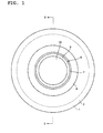
- FIG. 1 illustrates a plan view of a piezoelectric-type electroacoustic conversion device of a first embodiment of the present invention
- FIG. 2 illustrates a cross-sectional view taken along the line II-II of FIG. 1
- the piezoelectric-type electroacoustic conversion device includes a ring-shaped frame 1.
- An outer periphery portion of a lower surface of a circular support plate 2, made of resin such as polyethylene terephthalate and polyester, is fixed to an upper surface of the frame 1 via an adhesive agent 3.
- a circular through hole 3 is provided in the center portion of the support plate 2.
- a piezoelectric element 8 is provided on a portion of the upper surface of the metal plate 4 positioned inward from the shock absorbing member 7, and on a portion of an upper surface of the shock absorbing member 7 positioned on an inner periphery portion of the shock absorbing member 7 and at a circumference of the portion of the upper surface of the metal plate 4.
- the piezoelectric element 8 is configured such that respective circular electrode layers 10 and 11 are provided on the upper surface and the lower surface of a circular piezoelectric element body 9, made of piezoelectric ceramics such as zirconate titanate salt and barium titanate.
- the lower surface of the electrode layer 11 on the lower surface side of the piezoelectric element 8 is fixed via an adhesive agent 12 to the portion of the upper surface of the metal plate 4 positioned inward from the shock absorbing member 7, and the portion of the upper surface of the shock absorbing member 7 positioned on the inner periphery portion of the shock absorbing member 7 and at the circumference of the portion of the upper surface of the metal plate 4.
- this piezoelectric-type electroacoustic conversion device when a voltage is applied between the both electrode layers 10 and 11 of the piezoelectric element 8, the piezoelectric element 8 vibrates with the metal plate 4 and the support plate 2 in response to the applied voltage, and a sound is emitted in accordance with the applied voltage, whereby the piezoelectric-type electroacoustic conversion device is utilized as a speaker.
- the piezoelectric element 8 vibrates in response to the shock, and energy generated in the centrifugal direction of the piezoelectric element 8 is transmitted to the shock absorbing member 7 at the outer periphery portion of the piezoelectric element 8 by means of the motion of the expansion in the diameter of the piezoelectric element 8, and the energy is absorbed by the shock absorbing member 7, whereby stress concentrated on a boundary surface between the outer periphery portion of the piezoelectric element 8 and the shock absorbing member 7 is spread, and the piezoelectric element 8, which includes the piezoelectric ceramics having brittleness, can be made resistant to damage.
- the mechanical quality factor of the piezoelectric element 8 can be reduced because a mechanical attenuation can be added to a portion where stress is concentrated on the boundary surface between the outer periphery portion of the piezoelectric element 8 and the shock absorbing member 7, by utilizing the internal losses (mechanical attenuation) of the shock absorbing member 7, made of the elastic materials such as the carbon-based material and poly urethane, and therefore the flatness of a frequency sound pressure characteristic can be improved.
- the support plate 2 made of resin and interposed between the frame 1 and the metal plate 4 can serve as a vibration amplification function which propagates the vibration of the piezoelectric element 8.
- FIG. 3 illustrates a cross-sectional view of the piezoelectric-type electroacoustic conversion device, which is similar to that in FIG. 2 , as a second embodiment of the present invention.
- This piezoelectric-type electroacoustic conversion device differs from the piezoelectric-type electroacoustic conversion device illustrated in FIG. 2 in terms of another piezoelectric element 23 provided on the lower surface of the metal plate 4. That is, a groove 21, whose cross section is formed in a rectangular shape, is provided in a ring shape and positioned inward from an outer periphery portion of the lower surface of the metal plate 4.
- a shock absorbing member 22, made of elastic materials such as the carbon-based material and polyurethane, is provided in the groove 21 of the metal plate 4. In this case, the lower surface of the shock absorbing member 22 is flush with the lower surface of the metal plate 4.
- Another piezoelectric element 23 is provided on a portion of the lower surface of the metal plate 4 positioned inward from the shock absorbing member 22, and on a portion of a lower surface of the shock absorbing member 22 positioned on an inner periphery portion of the shock absorbing member 22 and at a circumference of the portion of the lower surface of the metal plate 4.
- the piezoelectric element 23 is configured such that respective circular electrode layers 25 and 26 are provided on the upper surface and the lower surface of a circular piezoelectric element body 24, made of piezoelectric ceramics materials such as zirconate titanate salt and barium titanate.
- the upper surface of the electrode layer 25 on the upper surface side of the piezoelectric element 23 is fixed via an adhesive agent 27 to the portion of the lower surface of the metal plate 4 positioned inward from the shock absorbing member 22, and the portion of the lower surface of the shock absorbing member 22 positioned on the inner periphery portion of the shock absorbing member 22 and at the circumference of the portion of the lower surface of the metal plate 4.
- the piezoelectric element 23 is arranged in the through hole 3 of the support plate 2.
- the frequency sound pressure characteristics were examined for the piezoelectric-type electroacoustic conversion device illustrated in FIG. 2 , the piezoelectric-type electroacoustic conversion device illustrated in FIG. 3 , and a piezoelectric-type electroacoustic conversion device, in which the shock absorbing member 7 in FIG. 2 is not provided (that is, the groove 6 is not provided, either and whereby the upper surface of the metal plate 4 is flat), for the purpose of comparison, and the results illustrated in FIG. 4 were acquired.
- the two piezoelectric elements 8 and 23 are provided, so that the sound pressure level is high as a whole, as compared with the case of the first embodiment illustrated by the solid line.
- the present invention is a piezoelectric-type electroacoustic conversion device comprising: ring-shaped frame; a support plate an outer periphery portion of a lower surface of which is fixed to an upper surface of the frame, and which includes a through hole at a central portion thereof; a metal plate an outer periphery portion of a lower surface of which is fixed to a portion of an upper surface of the support plate positioned at a circumference of the through hole; a groove provided in a ring shape on an upper surface of the metal plate; a shock absorbing member provided in the groove of the metal plate; and a piezoelectric element wherein at least an outer periphery portion of a lower surface is fixed to an upper surface of the shock absorbing member.
- the present invention according to Supplementary Note 2 relates to the present invention claimed in Supplementary Note 1 of the piezoelectric-type electroacoustic conversion device, wherein the upper surface of the shock absorbing member is flush with the upper surface of the metal plate, and wherein the piezoelectric element is fixed to a portion of the upper surface of the metal plate positioned inward from the shock absorbing member, and a portion of the upper surface of the shock absorbing member positioned at a circumference of the portion of the upper surface of the metal plate.
- the present invention according to Supplementary Note 3 relates to the present invention claimed in Supplementary Note 1 or 2 of the piezoelectric-type electroacoustic conversion device, wherein the shock absorbing member is made of an elastic member.
- the present invention according to Supplementary Note 4 relates to the present invention claimed in any one of Supplementary Notes 1 to 3 of the piezoelectric-type electroacoustic conversion device, wherein the support plate is made of resin.
- the present invention according to Supplementary Note 5 relates to the present invention claimed in any one of Supplementary Notes 1 to 4 of the piezoelectric-type electroacoustic conversion device, wherein a groove is provided in a ring shape on a lower surface of the metal plate, and wherein an another shock absorbing member is provided in the groove on a lower surface side of the metal plate, and wherein an another piezoelectric element is fixed to a portion of the lower surface of the metal plate positioned inward from the another shock absorbing member, and a portion of a lower surface of the another shock absorbing member positioned at a circumference of the portion of the lower surface of the metal plate.
Landscapes
- Engineering & Computer Science (AREA)
- Physics & Mathematics (AREA)
- Acoustics & Sound (AREA)
- Signal Processing (AREA)
- Manufacturing & Machinery (AREA)
- Piezo-Electric Transducers For Audible Bands (AREA)
Abstract
Description
- The present invention relates to a piezoelectric-type electroacoustic conversion device.
- In a conventional piezoelectric-type electroacoustic conversion device, a piezoelectric element is used in which electrode layers are provided on the upper surface and the lower surface of a circular piezoelectric element body made of piezoelectric ceramics, and the electrode layer on the lower surface side of the piezoelectric element is fixed to the central portion of the upper surface of a circular metal plate via an adhesive agent (for example, see Patent Document 1). Regarding the piezoelectric-type electroacoustic conversion device, when a voltage is applied between the both electrode layers of the piezoelectric element, the piezoelectric element vibrates with the metal plate in response to the applied voltage, and a sound is emitted in accordance with the applied voltage, whereby the piezoelectric-type electroacoustic conversion device is utilized as a speaker.
- Patent Document 1:
JP 59-034800 - However, regarding the above-described conventional piezoelectric-type electroacoustic conversion device, there is a problem in that, when a shock due to a fall or the like is received, the piezoelectric element vibrates in response to the shock, and energy generated in the centrifugal direction of the piezoelectric element is transmitted to a metal plate at the outer periphery portion of the piezoelectric element by means of the motion of the expansion in the diameter of the piezoelectric element (extension and contraction motion in the direction toward the outer periphery), and, as a result, stress on a boundary surface between the outer periphery portion of the piezoelectric element and the metal plate is concentrated, whereby the piezoelectric element, which includes piezoelectric ceramics having brittleness, may be damaged at a portion where the stress is concentrated. Also, the piezoelectric ceramics has a high mechanical quality factor (Mechanical Q), so that sound pressure level is high near resonance frequencies, and whereas the sound pressure level is remarkably attenuated in the band other than the resonance frequencies, and there is a problem in that relatively large crests and troughs of the sound pressure occur with respect to a frequency sound pressure characteristic, whereby the flatness of frequency sound pressure characteristic is not considered to be good.
- Accordingly, an object of the present invention is to provide a piezoelectric-type electroacoustic conversion device in which, even when a shock due to a fall or the like is received, a piezoelectric element can be made resistant to damage, and the flatness of a frequency sound pressure characteristic can be improved.
- A piezoelectric-type electroacoustic conversion device according to the present invention includes: a ring-shaped frame; a support plate an outer periphery portion of a lower surface of which is fixed to an upper surface of the frame, and which includes a through hole at a central portion thereof; a metal plate an outer periphery portion of a lower surface of which is fixed to a portion of an upper surface of the support plate positioned at a circumference of the through hole; a groove provided in a ring shape on an upper surface of the metal plate; a shock absorbing member provided in the groove of the metal plate; and a piezoelectric element wherein at least an outer periphery portion of a lower surface is fixed to an upper surface of the shock absorbing member.
- According to the aspect of the present invention, even when a shock due to a fall or the like is received, the piezoelectric element can be made resistant to damage, and the flatness of a frequency sound pressure characteristic can be improved.
-
-
FIG. 1 is a plan view of a piezoelectric-type electroacoustic conversion device of a first embodiment of the present invention. -
FIG. 2 is a cross-sectional view taken along the line II-II ofFIG. 1 . -
FIG. 3 is a cross-sectional view of the piezoelectric-type electroacoustic conversion device, which is similar to that inFIG. 2 , as a second embodiment of the present invention. -
FIG. 4 is a diagram for describing frequency sound pressure characteristics. -
FIG. 1 illustrates a plan view of a piezoelectric-type electroacoustic conversion device of a first embodiment of the present invention, andFIG. 2 illustrates a cross-sectional view taken along the line II-II ofFIG. 1 . The piezoelectric-type electroacoustic conversion device includes a ring-shaped frame 1. An outer periphery portion of a lower surface of acircular support plate 2, made of resin such as polyethylene terephthalate and polyester, is fixed to an upper surface of theframe 1 via anadhesive agent 3. A circular throughhole 3 is provided in the center portion of thesupport plate 2. - An outer periphery portion of a lower surface of a
circular metal plate 4, made of stainless steel and the like, is fixed to a portion of an upper surface of thesupport plate 2 positioned at the circumference of the throughhole 3 via anadhesive agent 5. Agroove 6, whose cross section is formed in a rectangular shape, is provided in a ring shape and positioned inward from an outer periphery portion of an upper surface of themetal plate 4. Ashock absorbing member 7, made of elastic materials such as a carbon-based material and poly urethane, is provided in thegroove 6 of themetal plate 4. In this case, the upper surface of theshock absorbing member 7 is flush with the upper surface of themetal plate 4. - A
piezoelectric element 8 is provided on a portion of the upper surface of themetal plate 4 positioned inward from theshock absorbing member 7, and on a portion of an upper surface of theshock absorbing member 7 positioned on an inner periphery portion of theshock absorbing member 7 and at a circumference of the portion of the upper surface of themetal plate 4. Thepiezoelectric element 8 is configured such that respectivecircular electrode layers piezoelectric element body 9, made of piezoelectric ceramics such as zirconate titanate salt and barium titanate. Then, the lower surface of theelectrode layer 11 on the lower surface side of thepiezoelectric element 8 is fixed via anadhesive agent 12 to the portion of the upper surface of themetal plate 4 positioned inward from theshock absorbing member 7, and the portion of the upper surface of theshock absorbing member 7 positioned on the inner periphery portion of theshock absorbing member 7 and at the circumference of the portion of the upper surface of themetal plate 4. - Now, in this piezoelectric-type electroacoustic conversion device, when a voltage is applied between the both
electrode layers piezoelectric element 8, thepiezoelectric element 8 vibrates with themetal plate 4 and thesupport plate 2 in response to the applied voltage, and a sound is emitted in accordance with the applied voltage, whereby the piezoelectric-type electroacoustic conversion device is utilized as a speaker. - When a shock due to a fall or the like is received, the
piezoelectric element 8 vibrates in response to the shock, and energy generated in the centrifugal direction of thepiezoelectric element 8 is transmitted to theshock absorbing member 7 at the outer periphery portion of thepiezoelectric element 8 by means of the motion of the expansion in the diameter of thepiezoelectric element 8, and the energy is absorbed by theshock absorbing member 7, whereby stress concentrated on a boundary surface between the outer periphery portion of thepiezoelectric element 8 and theshock absorbing member 7 is spread, and thepiezoelectric element 8, which includes the piezoelectric ceramics having brittleness, can be made resistant to damage. - Also, although the piezoelectric ceramics has a high mechanical quality factor, the mechanical quality factor of the
piezoelectric element 8 can be reduced because a mechanical attenuation can be added to a portion where stress is concentrated on the boundary surface between the outer periphery portion of thepiezoelectric element 8 and theshock absorbing member 7, by utilizing the internal losses (mechanical attenuation) of theshock absorbing member 7, made of the elastic materials such as the carbon-based material and poly urethane, and therefore the flatness of a frequency sound pressure characteristic can be improved. Moreover, in this case, thesupport plate 2 made of resin and interposed between theframe 1 and themetal plate 4 can serve as a vibration amplification function which propagates the vibration of thepiezoelectric element 8. -
FIG. 3 illustrates a cross-sectional view of the piezoelectric-type electroacoustic conversion device, which is similar to that inFIG. 2 , as a second embodiment of the present invention. This piezoelectric-type electroacoustic conversion device differs from the piezoelectric-type electroacoustic conversion device illustrated inFIG. 2 in terms of anotherpiezoelectric element 23 provided on the lower surface of themetal plate 4. That is, agroove 21, whose cross section is formed in a rectangular shape, is provided in a ring shape and positioned inward from an outer periphery portion of the lower surface of themetal plate 4. Ashock absorbing member 22, made of elastic materials such as the carbon-based material and polyurethane, is provided in thegroove 21 of themetal plate 4. In this case, the lower surface of theshock absorbing member 22 is flush with the lower surface of themetal plate 4. - Another
piezoelectric element 23 is provided on a portion of the lower surface of themetal plate 4 positioned inward from theshock absorbing member 22, and on a portion of a lower surface of theshock absorbing member 22 positioned on an inner periphery portion of theshock absorbing member 22 and at a circumference of the portion of the lower surface of themetal plate 4. Thepiezoelectric element 23 is configured such that respectivecircular electrode layers piezoelectric element body 24, made of piezoelectric ceramics materials such as zirconate titanate salt and barium titanate. Then, the upper surface of theelectrode layer 25 on the upper surface side of thepiezoelectric element 23 is fixed via anadhesive agent 27 to the portion of the lower surface of themetal plate 4 positioned inward from theshock absorbing member 22, and the portion of the lower surface of theshock absorbing member 22 positioned on the inner periphery portion of theshock absorbing member 22 and at the circumference of the portion of the lower surface of themetal plate 4. In this state, thepiezoelectric element 23 is arranged in the throughhole 3 of thesupport plate 2. - Herein, the frequency sound pressure characteristics were examined for the piezoelectric-type electroacoustic conversion device illustrated in
FIG. 2 , the piezoelectric-type electroacoustic conversion device illustrated inFIG. 3 , and a piezoelectric-type electroacoustic conversion device, in which theshock absorbing member 7 inFIG. 2 is not provided (that is, thegroove 6 is not provided, either and whereby the upper surface of themetal plate 4 is flat), for the purpose of comparison, and the results illustrated inFIG. 4 were acquired. - Here, in the case of the piezoelectric-type electroacoustic conversion device (comparative example), in which the
shock absorbing member 7 inFIG. 2 is not provided, for the purpose of comparison, as illustrated by a dotted line inFIG. 4 , there are two relatively large peaks in crests and troughs, therefore the flatness of the frequency sound pressure characteristic is not considered to be good. In contrast, in the case of the piezoelectric-type electroacoustic conversion device (first embodiment) illustrated inFIG. 2 , as illustrated by a solid line inFIG. 4 , the change between crests and troughs gently slopes in a band interposed between the two relatively large peaks illustrated by the dotted line in the comparative example, and the flatness of the frequency sound pressure characteristic is better. - In the case of the piezoelectric-type electroacoustic conversion device (second embodiment) illustrated in
FIG. 3 , as illustrated by a dashed-dotted line inFIG. 4 , the change between crests and troughs gently slopes in the band interposed between the two relatively large peaks illustrated by the dotted line in the comparative example, and the flatness of the frequency sound pressure characteristic is better. Also, in the case of the second embodiment illustrated by the dashed-dotted line, as illustrated inFIG. 3 , the twopiezoelectric elements - Hereinafter, several embodiments of this invention are summarized in the Supplementary Notes described below.
- The present invention according to
Supplementary Note 1 is a piezoelectric-type electroacoustic conversion device comprising: ring-shaped frame; a support plate an outer periphery portion of a lower surface of which is fixed to an upper surface of the frame, and which includes a through hole at a central portion thereof; a metal plate an outer periphery portion of a lower surface of which is fixed to a portion of an upper surface of the support plate positioned at a circumference of the through hole; a groove provided in a ring shape on an upper surface of the metal plate; a shock absorbing member provided in the groove of the metal plate; and a piezoelectric element wherein at least an outer periphery portion of a lower surface is fixed to an upper surface of the shock absorbing member. - The present invention according to
Supplementary Note 2 relates to the present invention claimed inSupplementary Note 1 of the piezoelectric-type electroacoustic conversion device, wherein the upper surface of the shock absorbing member is flush with the upper surface of the metal plate, and wherein the piezoelectric element is fixed to a portion of the upper surface of the metal plate positioned inward from the shock absorbing member, and a portion of the upper surface of the shock absorbing member positioned at a circumference of the portion of the upper surface of the metal plate. - The present invention according to
Supplementary Note 3 relates to the present invention claimed inSupplementary Note - The present invention according to
Supplementary Note 4 relates to the present invention claimed in any one ofSupplementary Notes 1 to 3 of the piezoelectric-type electroacoustic conversion device, wherein the support plate is made of resin. - The present invention according to
Supplementary Note 5 relates to the present invention claimed in any one ofSupplementary Notes 1 to 4 of the piezoelectric-type electroacoustic conversion device, wherein a groove is provided in a ring shape on a lower surface of the metal plate, and wherein an another shock absorbing member is provided in the groove on a lower surface side of the metal plate, and wherein an another piezoelectric element is fixed to a portion of the lower surface of the metal plate positioned inward from the another shock absorbing member, and a portion of a lower surface of the another shock absorbing member positioned at a circumference of the portion of the lower surface of the metal plate. -
- 1
- frame
- 2
- support plate
- 4
- metal plate
- 6
- groove
- 7
- shock absorbing member
- 8
- piezoelectric element
- 21
- groove
- 22
- shock absorbing member
- 23
- piezoelectric element
Claims (5)
- A piezoelectric-type electroacoustic conversion device comprising:a ring-shaped frame;a support plate an outer periphery portion of a lower surface of which is fixed to an upper surface of the frame, and which includes a through hole at a central portion thereof;a metal plate an outer periphery portion of a lower surface of which is fixed to a portion of an upper surface of the support plate positioned at a circumference of the through hole;a groove provided in a ring shape on an upper surface of the metal plate;a shock absorbing member provided in the groove of the metal plate; anda piezoelectric element wherein at least an outer periphery portion of a lower surface is fixed to an upper surface of the shock absorbing member.
- The piezoelectric-type electroacoustic conversion device according to claim 1,
wherein the upper surface of the shock absorbing member is flush with the upper surface of the metal plate, and
wherein the piezoelectric element is fixed to a portion of the upper surface of the metal plate positioned inward from the shock absorbing member, and a portion of the upper surface of the shock absorbing member positioned at a circumference of the portion of the upper surface of the metal plate. - The piezoelectric-type electroacoustic conversion device according to claim 1 or 2, wherein the shock absorbing member is made of an elastic member.
- The piezoelectric-type electroacoustic conversion device according to any one of claims 1 to 3, wherein the support plate is made of resin.
- The piezoelectric-type electroacoustic conversion device according to any one of claims 1 to 4,
wherein a groove is provided in a ring shape on a lower surface of the metal plate, and
wherein an another shock absorbing member is provided in the groove on a lower surface side of the metal plate, and
wherein an another piezoelectric element is fixed to a portion of the lower surface of the metal plate positioned inward from the another shock absorbing member, and a portion of a lower surface of the another shock absorbing member positioned at a circumference of the portion of the lower surface of the metal plate.
Applications Claiming Priority (2)
| Application Number | Priority Date | Filing Date | Title |
|---|---|---|---|
| JP2012032890 | 2012-02-17 | ||
| PCT/JP2012/006376 WO2013121477A1 (en) | 2012-02-17 | 2012-10-04 | Piezoelectric-type electroacoustic conversion device |
Publications (3)
| Publication Number | Publication Date |
|---|---|
| EP2816821A1 true EP2816821A1 (en) | 2014-12-24 |
| EP2816821A4 EP2816821A4 (en) | 2015-10-21 |
| EP2816821B1 EP2816821B1 (en) | 2017-02-22 |
Family
ID=48983647
Family Applications (1)
| Application Number | Title | Priority Date | Filing Date |
|---|---|---|---|
| EP12868532.8A Not-in-force EP2816821B1 (en) | 2012-02-17 | 2012-10-04 | Piezoelectric-type electroacoustic conversion device |
Country Status (4)
| Country | Link |
|---|---|
| US (1) | US20150008794A1 (en) |
| EP (1) | EP2816821B1 (en) |
| JP (1) | JP6016131B2 (en) |
| WO (1) | WO2013121477A1 (en) |
Families Citing this family (1)
| Publication number | Priority date | Publication date | Assignee | Title |
|---|---|---|---|---|
| JP6617504B2 (en) * | 2015-10-02 | 2019-12-11 | セイコーエプソン株式会社 | Piezoelectric element, probe and ultrasonic measuring device |
Family Cites Families (7)
| Publication number | Priority date | Publication date | Assignee | Title |
|---|---|---|---|---|
| JPS5934800A (en) | 1982-08-20 | 1984-02-25 | Nippon Telegr & Teleph Corp <Ntt> | Piezoelectric electroacoustic transducer |
| JP2004058668A (en) * | 2000-05-18 | 2004-02-26 | Seiko Epson Corp | Mounting structure and module |
| NO317922B1 (en) * | 2003-08-25 | 2005-01-03 | Tandberg Telecom As | magnet Microphone |
| JP2004364334A (en) * | 2004-08-13 | 2004-12-24 | Taiheiyo Cement Corp | Piezoelectric acoustic transducer |
| JP4701059B2 (en) * | 2005-10-04 | 2011-06-15 | 東光東芝メーターシステムズ株式会社 | Ultrasonic sensor, manufacturing method thereof, and optimum design apparatus thereof |
| JP4185946B2 (en) * | 2006-07-20 | 2008-11-26 | ホシデン株式会社 | Piezoelectric electroacoustic transducer |
| US8991022B2 (en) * | 2009-01-07 | 2015-03-31 | Daishinku Corporation | Method for manufacturing piezoelectric resonator device |
-
2012
- 2012-10-04 US US14/379,366 patent/US20150008794A1/en not_active Abandoned
- 2012-10-04 EP EP12868532.8A patent/EP2816821B1/en not_active Not-in-force
- 2012-10-04 JP JP2013558585A patent/JP6016131B2/en not_active Expired - Fee Related
- 2012-10-04 WO PCT/JP2012/006376 patent/WO2013121477A1/en not_active Ceased
Also Published As
| Publication number | Publication date |
|---|---|
| EP2816821A4 (en) | 2015-10-21 |
| JPWO2013121477A1 (en) | 2015-05-11 |
| JP6016131B2 (en) | 2016-10-26 |
| WO2013121477A1 (en) | 2013-08-22 |
| US20150008794A1 (en) | 2015-01-08 |
| EP2816821B1 (en) | 2017-02-22 |
Similar Documents
| Publication | Publication Date | Title |
|---|---|---|
| US8670578B2 (en) | Piezoelectric actuator and electronic device | |
| JP5954181B2 (en) | Oscillator and electronic device | |
| CN110987159B (en) | Sound pressure sensor | |
| KR102497096B1 (en) | Perforated piezoelectric hydrophone, antenna comprising a plurality of hydrophones and method for making said hydrophone | |
| US10178472B1 (en) | Omnidirectional acoustic sensor | |
| US9392375B2 (en) | Acoustic generator, acoustic generation device, and electronic device | |
| CN110169085B (en) | System of non-acoustic sensors combined with MEMS microphones | |
| KR101387064B1 (en) | Piezoelectric stack transducer | |
| KR101392744B1 (en) | Built-up type piezoelectric speaker device | |
| JP2016086409A (en) | Electroacoustic conversion device | |
| US9925562B2 (en) | Vibrator | |
| US5018116A (en) | Inter-element mounting for stacked piezoelectric transducers | |
| EP2816821B1 (en) | Piezoelectric-type electroacoustic conversion device | |
| EP2658283A1 (en) | Oscillator device and electronic instrument | |
| EP2693771B1 (en) | Oscillator and electronic device | |
| JP5023244B1 (en) | Vibration power generator | |
| JPS61150499A (en) | Separate type piezoelectric diaphragm | |
| JP5359818B2 (en) | Piezoelectric actuator and electronic device | |
| US9338556B2 (en) | Electroacoustic transducer, manufacturing method thereof, and electronic device utilizing same | |
| JP6386925B2 (en) | SOUND GENERATOR AND ELECTRONIC DEVICE USING THE SAME | |
| JP2012217037A (en) | Electronic device | |
| US20160066096A1 (en) | Acoustic transducer | |
| US20180250710A1 (en) | Acoustic sensor for emitting and/or receiving acoustic signals | |
| US20230059140A1 (en) | Microphone back panel and microphone | |
| JP2012134595A (en) | Oscillation device and electronic apparatus |
Legal Events
| Date | Code | Title | Description |
|---|---|---|---|
| PUAI | Public reference made under article 153(3) epc to a published international application that has entered the european phase |
Free format text: ORIGINAL CODE: 0009012 |
|
| 17P | Request for examination filed |
Effective date: 20140903 |
|
| AK | Designated contracting states |
Kind code of ref document: A1 Designated state(s): AL AT BE BG CH CY CZ DE DK EE ES FI FR GB GR HR HU IE IS IT LI LT LU LV MC MK MT NL NO PL PT RO RS SE SI SK SM TR |
|
| AX | Request for extension of the european patent |
Extension state: BA ME |
|
| DAX | Request for extension of the european patent (deleted) | ||
| RAP1 | Party data changed (applicant data changed or rights of an application transferred) |
Owner name: NEC CORPORATION |
|
| RA4 | Supplementary search report drawn up and despatched (corrected) |
Effective date: 20150921 |
|
| RIC1 | Information provided on ipc code assigned before grant |
Ipc: H01L 41/09 20060101ALI20150915BHEP Ipc: H01L 41/187 20060101ALI20150915BHEP Ipc: H04R 17/00 20060101AFI20150915BHEP |
|
| GRAP | Despatch of communication of intention to grant a patent |
Free format text: ORIGINAL CODE: EPIDOSNIGR1 |
|
| GRAJ | Information related to disapproval of communication of intention to grant by the applicant or resumption of examination proceedings by the epo deleted |
Free format text: ORIGINAL CODE: EPIDOSDIGR1 |
|
| INTG | Intention to grant announced |
Effective date: 20160707 |
|
| GRAP | Despatch of communication of intention to grant a patent |
Free format text: ORIGINAL CODE: EPIDOSNIGR1 |
|
| INTC | Intention to grant announced (deleted) | ||
| INTG | Intention to grant announced |
Effective date: 20160817 |
|
| GRAJ | Information related to disapproval of communication of intention to grant by the applicant or resumption of examination proceedings by the epo deleted |
Free format text: ORIGINAL CODE: EPIDOSDIGR1 |
|
| GRAR | Information related to intention to grant a patent recorded |
Free format text: ORIGINAL CODE: EPIDOSNIGR71 |
|
| GRAS | Grant fee paid |
Free format text: ORIGINAL CODE: EPIDOSNIGR3 |
|
| INTC | Intention to grant announced (deleted) | ||
| RIN1 | Information on inventor provided before grant (corrected) |
Inventor name: ONISHI, YASUHARU Inventor name: KOMODA, MOTOYOSHI Inventor name: MURATA, YUKIO Inventor name: KISHINAMI, YUICHIRO |
|
| GRAA | (expected) grant |
Free format text: ORIGINAL CODE: 0009210 |
|
| RIC1 | Information provided on ipc code assigned before grant |
Ipc: H01L 41/187 20060101ALI20161219BHEP Ipc: H04R 31/00 20060101ALI20161219BHEP Ipc: H04R 17/00 20060101AFI20161219BHEP Ipc: H01L 41/09 20060101ALI20161219BHEP |
|
| AK | Designated contracting states |
Kind code of ref document: B1 Designated state(s): AL AT BE BG CH CY CZ DE DK EE ES FI FR GB GR HR HU IE IS IT LI LT LU LV MC MK MT NL NO PL PT RO RS SE SI SK SM TR |
|
| INTG | Intention to grant announced |
Effective date: 20170113 |
|
| REG | Reference to a national code |
Ref country code: GB Ref legal event code: FG4D |
|
| REG | Reference to a national code |
Ref country code: CH Ref legal event code: EP |
|
| REG | Reference to a national code |
Ref country code: AT Ref legal event code: REF Ref document number: 870118 Country of ref document: AT Kind code of ref document: T Effective date: 20170315 |
|
| REG | Reference to a national code |
Ref country code: IE Ref legal event code: FG4D |
|
| REG | Reference to a national code |
Ref country code: DE Ref legal event code: R096 Ref document number: 602012029074 Country of ref document: DE |
|
| REG | Reference to a national code |
Ref country code: LT Ref legal event code: MG4D |
|
| REG | Reference to a national code |
Ref country code: NL Ref legal event code: MP Effective date: 20170222 |
|
| REG | Reference to a national code |
Ref country code: AT Ref legal event code: MK05 Ref document number: 870118 Country of ref document: AT Kind code of ref document: T Effective date: 20170222 |
|
| PG25 | Lapsed in a contracting state [announced via postgrant information from national office to epo] |
Ref country code: LT Free format text: LAPSE BECAUSE OF FAILURE TO SUBMIT A TRANSLATION OF THE DESCRIPTION OR TO PAY THE FEE WITHIN THE PRESCRIBED TIME-LIMIT Effective date: 20170222 Ref country code: NO Free format text: LAPSE BECAUSE OF FAILURE TO SUBMIT A TRANSLATION OF THE DESCRIPTION OR TO PAY THE FEE WITHIN THE PRESCRIBED TIME-LIMIT Effective date: 20170522 Ref country code: GR Free format text: LAPSE BECAUSE OF FAILURE TO SUBMIT A TRANSLATION OF THE DESCRIPTION OR TO PAY THE FEE WITHIN THE PRESCRIBED TIME-LIMIT Effective date: 20170523 Ref country code: HR Free format text: LAPSE BECAUSE OF FAILURE TO SUBMIT A TRANSLATION OF THE DESCRIPTION OR TO PAY THE FEE WITHIN THE PRESCRIBED TIME-LIMIT Effective date: 20170222 Ref country code: FI Free format text: LAPSE BECAUSE OF FAILURE TO SUBMIT A TRANSLATION OF THE DESCRIPTION OR TO PAY THE FEE WITHIN THE PRESCRIBED TIME-LIMIT Effective date: 20170222 |
|
| PG25 | Lapsed in a contracting state [announced via postgrant information from national office to epo] |
Ref country code: AT Free format text: LAPSE BECAUSE OF FAILURE TO SUBMIT A TRANSLATION OF THE DESCRIPTION OR TO PAY THE FEE WITHIN THE PRESCRIBED TIME-LIMIT Effective date: 20170222 Ref country code: BG Free format text: LAPSE BECAUSE OF FAILURE TO SUBMIT A TRANSLATION OF THE DESCRIPTION OR TO PAY THE FEE WITHIN THE PRESCRIBED TIME-LIMIT Effective date: 20170522 Ref country code: SE Free format text: LAPSE BECAUSE OF FAILURE TO SUBMIT A TRANSLATION OF THE DESCRIPTION OR TO PAY THE FEE WITHIN THE PRESCRIBED TIME-LIMIT Effective date: 20170222 Ref country code: PT Free format text: LAPSE BECAUSE OF FAILURE TO SUBMIT A TRANSLATION OF THE DESCRIPTION OR TO PAY THE FEE WITHIN THE PRESCRIBED TIME-LIMIT Effective date: 20170622 Ref country code: NL Free format text: LAPSE BECAUSE OF FAILURE TO SUBMIT A TRANSLATION OF THE DESCRIPTION OR TO PAY THE FEE WITHIN THE PRESCRIBED TIME-LIMIT Effective date: 20170222 Ref country code: LV Free format text: LAPSE BECAUSE OF FAILURE TO SUBMIT A TRANSLATION OF THE DESCRIPTION OR TO PAY THE FEE WITHIN THE PRESCRIBED TIME-LIMIT Effective date: 20170222 Ref country code: RS Free format text: LAPSE BECAUSE OF FAILURE TO SUBMIT A TRANSLATION OF THE DESCRIPTION OR TO PAY THE FEE WITHIN THE PRESCRIBED TIME-LIMIT Effective date: 20170222 Ref country code: ES Free format text: LAPSE BECAUSE OF FAILURE TO SUBMIT A TRANSLATION OF THE DESCRIPTION OR TO PAY THE FEE WITHIN THE PRESCRIBED TIME-LIMIT Effective date: 20170222 |
|
| REG | Reference to a national code |
Ref country code: FR Ref legal event code: PLFP Year of fee payment: 6 |
|
| PG25 | Lapsed in a contracting state [announced via postgrant information from national office to epo] |
Ref country code: SK Free format text: LAPSE BECAUSE OF FAILURE TO SUBMIT A TRANSLATION OF THE DESCRIPTION OR TO PAY THE FEE WITHIN THE PRESCRIBED TIME-LIMIT Effective date: 20170222 Ref country code: CZ Free format text: LAPSE BECAUSE OF FAILURE TO SUBMIT A TRANSLATION OF THE DESCRIPTION OR TO PAY THE FEE WITHIN THE PRESCRIBED TIME-LIMIT Effective date: 20170222 Ref country code: EE Free format text: LAPSE BECAUSE OF FAILURE TO SUBMIT A TRANSLATION OF THE DESCRIPTION OR TO PAY THE FEE WITHIN THE PRESCRIBED TIME-LIMIT Effective date: 20170222 Ref country code: RO Free format text: LAPSE BECAUSE OF FAILURE TO SUBMIT A TRANSLATION OF THE DESCRIPTION OR TO PAY THE FEE WITHIN THE PRESCRIBED TIME-LIMIT Effective date: 20170222 Ref country code: IT Free format text: LAPSE BECAUSE OF FAILURE TO SUBMIT A TRANSLATION OF THE DESCRIPTION OR TO PAY THE FEE WITHIN THE PRESCRIBED TIME-LIMIT Effective date: 20170222 |
|
| REG | Reference to a national code |
Ref country code: DE Ref legal event code: R097 Ref document number: 602012029074 Country of ref document: DE |
|
| PG25 | Lapsed in a contracting state [announced via postgrant information from national office to epo] |
Ref country code: DK Free format text: LAPSE BECAUSE OF FAILURE TO SUBMIT A TRANSLATION OF THE DESCRIPTION OR TO PAY THE FEE WITHIN THE PRESCRIBED TIME-LIMIT Effective date: 20170222 Ref country code: SM Free format text: LAPSE BECAUSE OF FAILURE TO SUBMIT A TRANSLATION OF THE DESCRIPTION OR TO PAY THE FEE WITHIN THE PRESCRIBED TIME-LIMIT Effective date: 20170222 Ref country code: PL Free format text: LAPSE BECAUSE OF FAILURE TO SUBMIT A TRANSLATION OF THE DESCRIPTION OR TO PAY THE FEE WITHIN THE PRESCRIBED TIME-LIMIT Effective date: 20170222 |
|
| PLBE | No opposition filed within time limit |
Free format text: ORIGINAL CODE: 0009261 |
|
| STAA | Information on the status of an ep patent application or granted ep patent |
Free format text: STATUS: NO OPPOSITION FILED WITHIN TIME LIMIT |
|
| 26N | No opposition filed |
Effective date: 20171123 |
|
| PG25 | Lapsed in a contracting state [announced via postgrant information from national office to epo] |
Ref country code: SI Free format text: LAPSE BECAUSE OF FAILURE TO SUBMIT A TRANSLATION OF THE DESCRIPTION OR TO PAY THE FEE WITHIN THE PRESCRIBED TIME-LIMIT Effective date: 20170222 |
|
| PG25 | Lapsed in a contracting state [announced via postgrant information from national office to epo] |
Ref country code: MC Free format text: LAPSE BECAUSE OF FAILURE TO SUBMIT A TRANSLATION OF THE DESCRIPTION OR TO PAY THE FEE WITHIN THE PRESCRIBED TIME-LIMIT Effective date: 20170222 |
|
| REG | Reference to a national code |
Ref country code: CH Ref legal event code: PL |
|
| REG | Reference to a national code |
Ref country code: IE Ref legal event code: MM4A |
|
| PG25 | Lapsed in a contracting state [announced via postgrant information from national office to epo] |
Ref country code: LI Free format text: LAPSE BECAUSE OF NON-PAYMENT OF DUE FEES Effective date: 20171031 Ref country code: LU Free format text: LAPSE BECAUSE OF NON-PAYMENT OF DUE FEES Effective date: 20171004 Ref country code: CH Free format text: LAPSE BECAUSE OF NON-PAYMENT OF DUE FEES Effective date: 20171031 |
|
| REG | Reference to a national code |
Ref country code: BE Ref legal event code: MM Effective date: 20171031 |
|
| PG25 | Lapsed in a contracting state [announced via postgrant information from national office to epo] |
Ref country code: BE Free format text: LAPSE BECAUSE OF NON-PAYMENT OF DUE FEES Effective date: 20171031 |
|
| REG | Reference to a national code |
Ref country code: FR Ref legal event code: PLFP Year of fee payment: 7 |
|
| PG25 | Lapsed in a contracting state [announced via postgrant information from national office to epo] |
Ref country code: MT Free format text: LAPSE BECAUSE OF NON-PAYMENT OF DUE FEES Effective date: 20171004 |
|
| PG25 | Lapsed in a contracting state [announced via postgrant information from national office to epo] |
Ref country code: IE Free format text: LAPSE BECAUSE OF NON-PAYMENT OF DUE FEES Effective date: 20171004 |
|
| PGFP | Annual fee paid to national office [announced via postgrant information from national office to epo] |
Ref country code: FR Payment date: 20180913 Year of fee payment: 7 |
|
| PGFP | Annual fee paid to national office [announced via postgrant information from national office to epo] |
Ref country code: DE Payment date: 20180918 Year of fee payment: 7 |
|
| PGFP | Annual fee paid to national office [announced via postgrant information from national office to epo] |
Ref country code: GB Payment date: 20181003 Year of fee payment: 7 |
|
| PG25 | Lapsed in a contracting state [announced via postgrant information from national office to epo] |
Ref country code: HU Free format text: LAPSE BECAUSE OF FAILURE TO SUBMIT A TRANSLATION OF THE DESCRIPTION OR TO PAY THE FEE WITHIN THE PRESCRIBED TIME-LIMIT; INVALID AB INITIO Effective date: 20121004 |
|
| PG25 | Lapsed in a contracting state [announced via postgrant information from national office to epo] |
Ref country code: CY Free format text: LAPSE BECAUSE OF FAILURE TO SUBMIT A TRANSLATION OF THE DESCRIPTION OR TO PAY THE FEE WITHIN THE PRESCRIBED TIME-LIMIT Effective date: 20170222 |
|
| PG25 | Lapsed in a contracting state [announced via postgrant information from national office to epo] |
Ref country code: MK Free format text: LAPSE BECAUSE OF FAILURE TO SUBMIT A TRANSLATION OF THE DESCRIPTION OR TO PAY THE FEE WITHIN THE PRESCRIBED TIME-LIMIT Effective date: 20170222 |
|
| PG25 | Lapsed in a contracting state [announced via postgrant information from national office to epo] |
Ref country code: TR Free format text: LAPSE BECAUSE OF FAILURE TO SUBMIT A TRANSLATION OF THE DESCRIPTION OR TO PAY THE FEE WITHIN THE PRESCRIBED TIME-LIMIT Effective date: 20170222 |
|
| REG | Reference to a national code |
Ref country code: DE Ref legal event code: R119 Ref document number: 602012029074 Country of ref document: DE |
|
| PG25 | Lapsed in a contracting state [announced via postgrant information from national office to epo] |
Ref country code: AL Free format text: LAPSE BECAUSE OF FAILURE TO SUBMIT A TRANSLATION OF THE DESCRIPTION OR TO PAY THE FEE WITHIN THE PRESCRIBED TIME-LIMIT Effective date: 20170222 Ref country code: DE Free format text: LAPSE BECAUSE OF NON-PAYMENT OF DUE FEES Effective date: 20200501 Ref country code: IS Free format text: LAPSE BECAUSE OF FAILURE TO SUBMIT A TRANSLATION OF THE DESCRIPTION OR TO PAY THE FEE WITHIN THE PRESCRIBED TIME-LIMIT Effective date: 20170622 |
|
| GBPC | Gb: european patent ceased through non-payment of renewal fee |
Effective date: 20191004 |
|
| PG25 | Lapsed in a contracting state [announced via postgrant information from national office to epo] |
Ref country code: FR Free format text: LAPSE BECAUSE OF NON-PAYMENT OF DUE FEES Effective date: 20191031 Ref country code: GB Free format text: LAPSE BECAUSE OF NON-PAYMENT OF DUE FEES Effective date: 20191004 |