EP2816565A1 - Sludge-reduction steam generator and method for manufacturing tube plate of sludge-reduction steam generator - Google Patents
Sludge-reduction steam generator and method for manufacturing tube plate of sludge-reduction steam generator Download PDFInfo
- Publication number
- EP2816565A1 EP2816565A1 EP12868602.9A EP12868602A EP2816565A1 EP 2816565 A1 EP2816565 A1 EP 2816565A1 EP 12868602 A EP12868602 A EP 12868602A EP 2816565 A1 EP2816565 A1 EP 2816565A1
- Authority
- EP
- European Patent Office
- Prior art keywords
- steam generator
- sludge
- heat transfer
- transfer pipes
- tubular
- Prior art date
- Legal status (The legal status is an assumption and is not a legal conclusion. Google has not performed a legal analysis and makes no representation as to the accuracy of the status listed.)
- Granted
Links
Images

Classifications
-
- F—MECHANICAL ENGINEERING; LIGHTING; HEATING; WEAPONS; BLASTING
- F22—STEAM GENERATION
- F22B—METHODS OF STEAM GENERATION; STEAM BOILERS
- F22B37/00—Component parts or details of steam boilers
- F22B37/02—Component parts or details of steam boilers applicable to more than one kind or type of steam boiler
- F22B37/10—Water tubes; Accessories therefor
- F22B37/107—Protection of water tubes
-
- C—CHEMISTRY; METALLURGY
- C23—COATING METALLIC MATERIAL; COATING MATERIAL WITH METALLIC MATERIAL; CHEMICAL SURFACE TREATMENT; DIFFUSION TREATMENT OF METALLIC MATERIAL; COATING BY VACUUM EVAPORATION, BY SPUTTERING, BY ION IMPLANTATION OR BY CHEMICAL VAPOUR DEPOSITION, IN GENERAL; INHIBITING CORROSION OF METALLIC MATERIAL OR INCRUSTATION IN GENERAL
- C23F—NON-MECHANICAL REMOVAL OF METALLIC MATERIAL FROM SURFACE; INHIBITING CORROSION OF METALLIC MATERIAL OR INCRUSTATION IN GENERAL; MULTI-STEP PROCESSES FOR SURFACE TREATMENT OF METALLIC MATERIAL INVOLVING AT LEAST ONE PROCESS PROVIDED FOR IN CLASS C23 AND AT LEAST ONE PROCESS COVERED BY SUBCLASS C21D OR C22F OR CLASS C25
- C23F14/00—Inhibiting incrustation in apparatus for heating liquids for physical or chemical purposes
- C23F14/02—Inhibiting incrustation in apparatus for heating liquids for physical or chemical purposes by chemical means
-
- C—CHEMISTRY; METALLURGY
- C23—COATING METALLIC MATERIAL; COATING MATERIAL WITH METALLIC MATERIAL; CHEMICAL SURFACE TREATMENT; DIFFUSION TREATMENT OF METALLIC MATERIAL; COATING BY VACUUM EVAPORATION, BY SPUTTERING, BY ION IMPLANTATION OR BY CHEMICAL VAPOUR DEPOSITION, IN GENERAL; INHIBITING CORROSION OF METALLIC MATERIAL OR INCRUSTATION IN GENERAL
- C23C—COATING METALLIC MATERIAL; COATING MATERIAL WITH METALLIC MATERIAL; SURFACE TREATMENT OF METALLIC MATERIAL BY DIFFUSION INTO THE SURFACE, BY CHEMICAL CONVERSION OR SUBSTITUTION; COATING BY VACUUM EVAPORATION, BY SPUTTERING, BY ION IMPLANTATION OR BY CHEMICAL VAPOUR DEPOSITION, IN GENERAL
- C23C16/00—Chemical coating by decomposition of gaseous compounds, without leaving reaction products of surface material in the coating, i.e. chemical vapour deposition [CVD] processes
- C23C16/44—Chemical coating by decomposition of gaseous compounds, without leaving reaction products of surface material in the coating, i.e. chemical vapour deposition [CVD] processes characterised by the method of coating
- C23C16/50—Chemical coating by decomposition of gaseous compounds, without leaving reaction products of surface material in the coating, i.e. chemical vapour deposition [CVD] processes characterised by the method of coating using electric discharges
-
- F—MECHANICAL ENGINEERING; LIGHTING; HEATING; WEAPONS; BLASTING
- F01—MACHINES OR ENGINES IN GENERAL; ENGINE PLANTS IN GENERAL; STEAM ENGINES
- F01K—STEAM ENGINE PLANTS; STEAM ACCUMULATORS; ENGINE PLANTS NOT OTHERWISE PROVIDED FOR; ENGINES USING SPECIAL WORKING FLUIDS OR CYCLES
- F01K5/00—Plants characterised by use of means for storing steam in an alkali to increase steam pressure, e.g. of Honigmann or Koenemann type
- F01K5/02—Plants characterised by use of means for storing steam in an alkali to increase steam pressure, e.g. of Honigmann or Koenemann type used in regenerative installation
-
- F—MECHANICAL ENGINEERING; LIGHTING; HEATING; WEAPONS; BLASTING
- F22—STEAM GENERATION
- F22B—METHODS OF STEAM GENERATION; STEAM BOILERS
- F22B1/00—Methods of steam generation characterised by form of heating method
- F22B1/02—Methods of steam generation characterised by form of heating method by exploitation of the heat content of hot heat carriers
- F22B1/023—Methods of steam generation characterised by form of heating method by exploitation of the heat content of hot heat carriers with heating tubes for nuclear reactors, as long as they are not classified according to a specified heating fluid, in another group
- F22B1/025—Methods of steam generation characterised by form of heating method by exploitation of the heat content of hot heat carriers with heating tubes for nuclear reactors, as long as they are not classified according to a specified heating fluid, in another group with vertical U shaped tubes carried on a horizontal tube sheet
-
- F—MECHANICAL ENGINEERING; LIGHTING; HEATING; WEAPONS; BLASTING
- F22—STEAM GENERATION
- F22B—METHODS OF STEAM GENERATION; STEAM BOILERS
- F22B37/00—Component parts or details of steam boilers
- F22B37/02—Component parts or details of steam boilers applicable to more than one kind or type of steam boiler
- F22B37/10—Water tubes; Accessories therefor
- F22B37/20—Supporting arrangements, e.g. for securing water-tube sets
- F22B37/205—Supporting and spacing arrangements for tubes of a tube bundle
-
- F—MECHANICAL ENGINEERING; LIGHTING; HEATING; WEAPONS; BLASTING
- F22—STEAM GENERATION
- F22B—METHODS OF STEAM GENERATION; STEAM BOILERS
- F22B37/00—Component parts or details of steam boilers
- F22B37/02—Component parts or details of steam boilers applicable to more than one kind or type of steam boiler
- F22B37/48—Devices or arrangements for removing water, minerals or sludge from boilers ; Arrangement of cleaning apparatus in boilers; Combinations thereof with boilers
- F22B37/483—Devices or arrangements for removing water, minerals or sludge from boilers ; Arrangement of cleaning apparatus in boilers; Combinations thereof with boilers specially adapted for nuclear steam generators
-
- F—MECHANICAL ENGINEERING; LIGHTING; HEATING; WEAPONS; BLASTING
- F22—STEAM GENERATION
- F22B—METHODS OF STEAM GENERATION; STEAM BOILERS
- F22B37/00—Component parts or details of steam boilers
- F22B37/02—Component parts or details of steam boilers applicable to more than one kind or type of steam boiler
- F22B37/48—Devices or arrangements for removing water, minerals or sludge from boilers ; Arrangement of cleaning apparatus in boilers; Combinations thereof with boilers
- F22B37/54—De-sludging or blow-down devices
-
- F—MECHANICAL ENGINEERING; LIGHTING; HEATING; WEAPONS; BLASTING
- F28—HEAT EXCHANGE IN GENERAL
- F28D—HEAT-EXCHANGE APPARATUS, NOT PROVIDED FOR IN ANOTHER SUBCLASS, IN WHICH THE HEAT-EXCHANGE MEDIA DO NOT COME INTO DIRECT CONTACT
- F28D7/00—Heat-exchange apparatus having stationary tubular conduit assemblies for both heat-exchange media, the media being in contact with different sides of a conduit wall
- F28D7/06—Heat-exchange apparatus having stationary tubular conduit assemblies for both heat-exchange media, the media being in contact with different sides of a conduit wall the conduits having a single U-bend
-
- F—MECHANICAL ENGINEERING; LIGHTING; HEATING; WEAPONS; BLASTING
- F28—HEAT EXCHANGE IN GENERAL
- F28F—DETAILS OF HEAT-EXCHANGE AND HEAT-TRANSFER APPARATUS, OF GENERAL APPLICATION
- F28F19/00—Preventing the formation of deposits or corrosion, e.g. by using filters or scrapers
- F28F19/02—Preventing the formation of deposits or corrosion, e.g. by using filters or scrapers by using coatings, e.g. vitreous or enamel coatings
- F28F19/06—Preventing the formation of deposits or corrosion, e.g. by using filters or scrapers by using coatings, e.g. vitreous or enamel coatings of metal
-
- G—PHYSICS
- G21—NUCLEAR PHYSICS; NUCLEAR ENGINEERING
- G21C—NUCLEAR REACTORS
- G21C15/00—Cooling arrangements within the pressure vessel containing the core; Selection of specific coolants
- G21C15/16—Cooling arrangements within the pressure vessel containing the core; Selection of specific coolants comprising means for separating liquid and steam
-
- G—PHYSICS
- G21—NUCLEAR PHYSICS; NUCLEAR ENGINEERING
- G21C—NUCLEAR REACTORS
- G21C17/00—Monitoring; Testing ; Maintaining
- G21C17/017—Inspection or maintenance of pipe-lines or tubes in nuclear installations
-
- F—MECHANICAL ENGINEERING; LIGHTING; HEATING; WEAPONS; BLASTING
- F28—HEAT EXCHANGE IN GENERAL
- F28F—DETAILS OF HEAT-EXCHANGE AND HEAT-TRANSFER APPARATUS, OF GENERAL APPLICATION
- F28F19/00—Preventing the formation of deposits or corrosion, e.g. by using filters or scrapers
- F28F19/004—Preventing the formation of deposits or corrosion, e.g. by using filters or scrapers by using protective electric currents, voltages, cathodes, anodes, electric short-circuits
-
- G—PHYSICS
- G21—NUCLEAR PHYSICS; NUCLEAR ENGINEERING
- G21D—NUCLEAR POWER PLANT
- G21D1/00—Details of nuclear power plant
-
- Y—GENERAL TAGGING OF NEW TECHNOLOGICAL DEVELOPMENTS; GENERAL TAGGING OF CROSS-SECTIONAL TECHNOLOGIES SPANNING OVER SEVERAL SECTIONS OF THE IPC; TECHNICAL SUBJECTS COVERED BY FORMER USPC CROSS-REFERENCE ART COLLECTIONS [XRACs] AND DIGESTS
- Y02—TECHNOLOGIES OR APPLICATIONS FOR MITIGATION OR ADAPTATION AGAINST CLIMATE CHANGE
- Y02E—REDUCTION OF GREENHOUSE GAS [GHG] EMISSIONS, RELATED TO ENERGY GENERATION, TRANSMISSION OR DISTRIBUTION
- Y02E30/00—Energy generation of nuclear origin
-
- Y—GENERAL TAGGING OF NEW TECHNOLOGICAL DEVELOPMENTS; GENERAL TAGGING OF CROSS-SECTIONAL TECHNOLOGIES SPANNING OVER SEVERAL SECTIONS OF THE IPC; TECHNICAL SUBJECTS COVERED BY FORMER USPC CROSS-REFERENCE ART COLLECTIONS [XRACs] AND DIGESTS
- Y02—TECHNOLOGIES OR APPLICATIONS FOR MITIGATION OR ADAPTATION AGAINST CLIMATE CHANGE
- Y02E—REDUCTION OF GREENHOUSE GAS [GHG] EMISSIONS, RELATED TO ENERGY GENERATION, TRANSMISSION OR DISTRIBUTION
- Y02E30/00—Energy generation of nuclear origin
- Y02E30/30—Nuclear fission reactors
Definitions
- the present invention relates to a sludge-reduction steam generator and a method for manufacturing a tubular plate for a sludge-reduction steam generator, which can effectively remove sludge deposits from the inside of a steam generator of a pressurized light water reactor.
- a pressurized light water reactor nuclear power plant produces electric power through the steps of transferring heat generated from nuclear fuel, heating water supplied from the secondary side to convert the water into steam and carrying out mechanical work in a turbine using steam.
- a great deal of supplied water containing corrosion products of a system structure causes a phase change in the secondary side of the steam generator, and in this instance, the iron corrosion products contained in the supplied water are deposited in the lower part of the secondary side of the steam generator due to a low speed of a flow rate.
- the iron corrosion products are composed of 95.8% of hematite (Fe 2 0 3 ) and magnetite (Fe 3 0 4 ) and metallic oxides, and such iron corrosion products promote corrosion of a heat transfer pipe of the steam generator.
- the iron corrosion products which are deposited on a heat transfer pipe supporting plate (tubular pipe) obstruct a flow channel of cooling water so as to cause oscillation of a water level of the steam generator, and hence, cause power-reduction operation or an unexpected stop of a nuclear power plant.
- the present invention has been made in an effort to solve the above-mentioned problems occurring in the prior arts, and it is an object of the present invention to provide a sludge-reduction steam generator and a method for manufacturing a tubular plate for a sludge-reduction steam generator which can remarkably enhance a removal efficiency of corrosion products of a blow-down system of a steam generator in order to prevent deposition of iron corrosion products onto a tubular plate.
- the present invention provides a sludge-reduction steam generator including: a plurality of U-shaped heat transfer pipes disposed in such a way that heat-exchange hot water flows in a pressure container; and one or more tubular plates penetrated by and coupled to the heat transfer pipes so as to support the heat transfer pipes, wherein the tubular plates are provided with a coated layer which is coated with a ceramic material having the same surface electrokinetic polarity (zeta potential) as iron corrosion products in a predetermined range.
- zeta potential surface electrokinetic polarity
- the present invention provides a method for manufacturing tubular plates supporting a plurality of U-shaped heat transfer pipes, which are disposed in such a way that heat-exchange hot water flows in a pressure container, the method for manufacturing tubular plates for a sludge-reduction steam generator including the step of: coating a coated layer on the surface of the tubular plates which are completely molded by coating a ceramic material having the same surface electrokinetic polarity (zeta potential) as iron corrosion products in a predetermined range.
- zeta potential surface electrokinetic polarity
- the coated layer is coated on the surface of the tubular plates which support the heat transfer pipes of the steam generator by the chemical vapor deposition (CVD) or the plasma vapor deposition.
- CVD chemical vapor deposition
- plasma vapor deposition the plasma vapor deposition
- the ceramic material is one of titanium ceramic (TiO 2 ) and zirconium ceramic (ZrO 2 ).
- the sludge-reduction steam generator and the method for manufacturing the tubular plate for the sludge-reduction steam generator according to the preferred embodiment of the present invention can provide an effect that the coated layer made of titanium ceramic (TiO 2 ) or zirconium ceramic (ZrO 2 ) coated on the upper side of the heat transfer pipe supporting plates (tubular plate) below the steam generator prevents deposition of Fe 2 0 3 and Fe 3 0 4 which are the main ingredients of sludge of the secondary side of the steam generator and increases surface induction to thereby easily remove iron corrosion products by a blow-down system of the steam generator.
- TiO 2 titanium ceramic
- ZrO 2 zirconium ceramic
- the sludge-reduction steam generator and the method for manufacturing the tubular plate for the sludge-reduction steam generator according to the preferred embodiment of the present invention can reduce blocking of a flow channel of the steam generator, reduce fouling of the heat transfer pipes of the steam generator and increase thermal efficiency through the effective removal of sludge of the steam generator.
- the sludge-reduction steam generator and the method for manufacturing the tubular plate for the sludge-reduction steam generator according to the preferred embodiment of the present invention can reduce a damage of the heat transfer pipes in the heat transfer pipe supporting plates (tubular plates) by the sludge.
- sludge-reduction steam generator and the method for manufacturing the tubular plate for the sludge-reduction steam generator according to the preferred embodiment of the present invention can prevent corrosion of a gap between a tube of the steam generator and a tube seat to thereby increase the lifespan of the heat transfer pipes of the steam generator.
- FIG. 1 is a sectional view of a steam generator 1 according to a preferred embodiment of the present invention
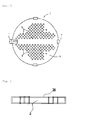
- FIG. 2 is a plan view of a heat transfer pipe supporting plate (tubular plate) 3 cut along the line of I-I of FIG. 1
- FIG. 3 is a schematic sectional view of the tubular plate 3 having a ceramic coated later 30.
- the sludge-reduction steam generator 1 includes: a plurality of U-shaped heat transfer pipes 2 disposed in such a way that heat-exchange hot water may flow in a pressure container; and one or more tubular plates 3 penetrated by and coupled to the heat transfer pipes 2 so as to support the heat transfer pipes 2, wherein the tubular plates 3, as shown in FIG. 3 , are provided with a coated layer 30 which is coated with a ceramic material having the same surface electrokinetic polarity (zeta potential) as iron corrosion products in a predetermined range.
- zeta potential surface electrokinetic polarity
- the pressurized container includes: a plurality of inlets 4 for introducing heated water thereinto; a plurality of outlets 5 for discharging water which moves through the heat transfer pipes 2 and is cooled after carrying out heat exchange; and a plurality of blow down ports 7 for removing deposits 6.
- the ceramic material is one of titanium ceramic (TiO 2 ) and zirconium ceramic (ZrO 2 ).
- the ceramic coated layer 30 is formed in such a way that TiO 2 or ZrO 2 which is a material existing stably in the high-temperature and high-pH environment of the secondary side of the steam generator is coated on the surface of the tubular plates 3 which support the heat transfer pipes 2 of the steam generator 1 by the chemical vapor deposition (CVD) or the plasma vapor deposition.
- CVD chemical vapor deposition
- the secondary side of the steam generator 1 is operated under the high-temperature, high-pressure and high-pH environment. Therefore, an operation range of an electrochemical potential (ECP) may be varied from (+) tens of mVs to (-) 500mVs.
- ECP electrochemical potential
- the zeta potential of Fe 2 0 3 and Fe 3 0 4 under temperature and pH for operating a general steam generator 1 is about -4mVs, and TiO 2 or ZrO 2 under the same temperature and pH conditions has the same structure and similar potential.
- the ceramic coated layer 30 is made of a material which can endure the change range of the ECP and the temperature change inside the steam generator 1 for a long time, and has the same polarity as magnetite of which zeta potential exists in a colloid state inside a dendrogram.
- the ceramic coated layer 30 which is made of TiO 2 or ZrO 2 causes electrically repulsive power against the deposits containing Fe 2 0 3 and Fe 3 0 4 . Accordingly, because friction force between the surface of the coated layer 30 and the deposits is reduced, the ceramic coated layer 30 increases surface mobility of the deposits which are iron-containing foreign matters to thereby induce the deposits to be easily removed through the blow down ports 7 of the steam generator 1. Therefore, corrosion product removal efficiency of the blow down system of the steam generator is also remarkably enhanced.
Landscapes
- Engineering & Computer Science (AREA)
- Physics & Mathematics (AREA)
- Mechanical Engineering (AREA)
- General Engineering & Computer Science (AREA)
- Chemical & Material Sciences (AREA)
- Thermal Sciences (AREA)
- High Energy & Nuclear Physics (AREA)
- Plasma & Fusion (AREA)
- Organic Chemistry (AREA)
- General Chemical & Material Sciences (AREA)
- Chemical Kinetics & Catalysis (AREA)
- Materials Engineering (AREA)
- Metallurgy (AREA)
- Combustion & Propulsion (AREA)
- Sustainable Energy (AREA)
- Sustainable Development (AREA)
- Life Sciences & Earth Sciences (AREA)
- Production Of Liquid Hydrocarbon Mixture For Refining Petroleum (AREA)
- Other Surface Treatments For Metallic Materials (AREA)
- Laminated Bodies (AREA)
- Waste-Gas Treatment And Other Accessory Devices For Furnaces (AREA)
Abstract
Description
- The present invention relates to a sludge-reduction steam generator and a method for manufacturing a tubular plate for a sludge-reduction steam generator, which can effectively remove sludge deposits from the inside of a steam generator of a pressurized light water reactor.
- A pressurized light water reactor nuclear power plant produces electric power through the steps of transferring heat generated from nuclear fuel, heating water supplied from the secondary side to convert the water into steam and carrying out mechanical work in a turbine using steam.
- A great deal of supplied water containing corrosion products of a system structure causes a phase change in the secondary side of the steam generator, and in this instance, the iron corrosion products contained in the supplied water are deposited in the lower part of the secondary side of the steam generator due to a low speed of a flow rate.
- The iron corrosion products are composed of 95.8% of hematite (Fe203) and magnetite (Fe304) and metallic oxides, and such iron corrosion products promote corrosion of a heat transfer pipe of the steam generator. Especially, the iron corrosion products which are deposited on a heat transfer pipe supporting plate (tubular pipe) obstruct a flow channel of cooling water so as to cause oscillation of a water level of the steam generator, and hence, cause power-reduction operation or an unexpected stop of a nuclear power plant.
- Hundreds of kilograms of such iron corrosion products are deposited in the lower part of the steam generator every year. Therefore, in order to remove the corrosion products deposited in the lower part of the steam generator, a steam generator blow-down system is operated to remove the corrosion products at the time of an overhaul, but it has a problem in that the corrosion products are not easily removed by the blow-down system because iron oxide is fixed on the floor of the steam generator.
- Moreover, recently, a measure to prevent the iron corrosion products from being deposited in the lower part of the steam generator using a dispersing agent has been effectively used, but it also has several problems in that using the dispersing agent requires high costs and causes side effects of water pollution.
- Accordingly, the present invention has been made in an effort to solve the above-mentioned problems occurring in the prior arts, and it is an object of the present invention to provide a sludge-reduction steam generator and a method for manufacturing a tubular plate for a sludge-reduction steam generator which can remarkably enhance a removal efficiency of corrosion products of a blow-down system of a steam generator in order to prevent deposition of iron corrosion products onto a tubular plate.
- To achieve the above objects, the present invention provides a sludge-reduction steam generator including: a plurality of U-shaped heat transfer pipes disposed in such a way that heat-exchange hot water flows in a pressure container; and one or more tubular plates penetrated by and coupled to the heat transfer pipes so as to support the heat transfer pipes, wherein the tubular plates are provided with a coated layer which is coated with a ceramic material having the same surface electrokinetic polarity (zeta potential) as iron corrosion products in a predetermined range.
- In another aspect of the present invention, the present invention provides a method for manufacturing tubular plates supporting a plurality of U-shaped heat transfer pipes, which are disposed in such a way that heat-exchange hot water flows in a pressure container, the method for manufacturing tubular plates for a sludge-reduction steam generator including the step of: coating a coated layer on the surface of the tubular plates which are completely molded by coating a ceramic material having the same surface electrokinetic polarity (zeta potential) as iron corrosion products in a predetermined range.
- The coated layer is coated on the surface of the tubular plates which support the heat transfer pipes of the steam generator by the chemical vapor deposition (CVD) or the plasma vapor deposition.
- The ceramic material is one of titanium ceramic (TiO2) and zirconium ceramic (ZrO2).
- The sludge-reduction steam generator and the method for manufacturing the tubular plate for the sludge-reduction steam generator according to the preferred embodiment of the present invention can provide an effect that the coated layer made of titanium ceramic (TiO2) or zirconium ceramic (ZrO2) coated on the upper side of the heat transfer pipe supporting plates (tubular plate) below the steam generator prevents deposition of Fe203 and Fe304 which are the main ingredients of sludge of the secondary side of the steam generator and increases surface induction to thereby easily remove iron corrosion products by a blow-down system of the steam generator.
- Furthermore, the sludge-reduction steam generator and the method for manufacturing the tubular plate for the sludge-reduction steam generator according to the preferred embodiment of the present invention can reduce blocking of a flow channel of the steam generator, reduce fouling of the heat transfer pipes of the steam generator and increase thermal efficiency through the effective removal of sludge of the steam generator.
- Additionally, the sludge-reduction steam generator and the method for manufacturing the tubular plate for the sludge-reduction steam generator according to the preferred embodiment of the present invention can reduce a damage of the heat transfer pipes in the heat transfer pipe supporting plates (tubular plates) by the sludge.
- In addition, sludge-reduction steam generator and the method for manufacturing the tubular plate for the sludge-reduction steam generator according to the preferred embodiment of the present invention can prevent corrosion of a gap between a tube of the steam generator and a tube seat to thereby increase the lifespan of the heat transfer pipes of the steam generator.
-
-
FIG. 1 is a sectional view of asteam generator 1 according to a preferred embodiment of the present invention. -
FIG. 2 is a plan view of a heat transfer pipe supporting plate (tubular plate) 3 cut along the line of I-I ofFIG. 1 . -
FIG. 3 is a schematic sectional view of thetubular plate 3 having a ceramic coated later 30. - Reference will be now made in detail to the preferred embodiment of the present invention with reference to the attached drawings.
-
FIG. 1 is a sectional view of asteam generator 1 according to a preferred embodiment of the present invention,FIG. 2 is a plan view of a heat transfer pipe supporting plate (tubular plate) 3 cut along the line of I-I ofFIG. 1 , andFIG. 3 is a schematic sectional view of thetubular plate 3 having a ceramic coated later 30. - As shown in
FIGS. 1 and2 , the sludge-reduction steam generator 1 includes: a plurality of U-shapedheat transfer pipes 2 disposed in such a way that heat-exchange hot water may flow in a pressure container; and one or moretubular plates 3 penetrated by and coupled to theheat transfer pipes 2 so as to support theheat transfer pipes 2, wherein thetubular plates 3, as shown inFIG. 3 , are provided with a coatedlayer 30 which is coated with a ceramic material having the same surface electrokinetic polarity (zeta potential) as iron corrosion products in a predetermined range. - The pressurized container includes: a plurality of inlets 4 for introducing heated water thereinto; a plurality of
outlets 5 for discharging water which moves through theheat transfer pipes 2 and is cooled after carrying out heat exchange; and a plurality of blow downports 7 for removingdeposits 6. - The ceramic material is one of titanium ceramic (TiO2) and zirconium ceramic (ZrO2).
- The ceramic coated
layer 30 is formed in such a way that TiO2 or ZrO2 which is a material existing stably in the high-temperature and high-pH environment of the secondary side of the steam generator is coated on the surface of thetubular plates 3 which support theheat transfer pipes 2 of thesteam generator 1 by the chemical vapor deposition (CVD) or the plasma vapor deposition. - The secondary side of the
steam generator 1 is operated under the high-temperature, high-pressure and high-pH environment. Therefore, an operation range of an electrochemical potential (ECP) may be varied from (+) tens of mVs to (-) 500mVs. The zeta potential of Fe203 and Fe304 under temperature and pH for operating ageneral steam generator 1 is about -4mVs, and TiO2 or ZrO2 under the same temperature and pH conditions has the same structure and similar potential. - The ceramic coated
layer 30 is made of a material which can endure the change range of the ECP and the temperature change inside thesteam generator 1 for a long time, and has the same polarity as magnetite of which zeta potential exists in a colloid state inside a dendrogram. - Therefore, the ceramic coated
layer 30 which is made of TiO2 or ZrO2 causes electrically repulsive power against the deposits containing Fe203 and Fe304. Accordingly, because friction force between the surface of the coatedlayer 30 and the deposits is reduced, the ceramic coatedlayer 30 increases surface mobility of the deposits which are iron-containing foreign matters to thereby induce the deposits to be easily removed through the blow downports 7 of thesteam generator 1. Therefore, corrosion product removal efficiency of the blow down system of the steam generator is also remarkably enhanced.
Claims (5)
- A sludge-reduction steam generator comprising:a plurality of U-shaped heat transfer pipes (2) disposed in such a way that heat-exchange hot water flows in a pressure container; andone or more tubular plates (3) coupled to the heat transfer pipes (2) so as to support the heat transfer pipes (2),wherein the tubular plates (3) are provided with a coated layer (30) which is coated with a ceramic material having the same surface electrokinetic polarity as iron corrosion products in a predetermined range.
- The sludge-reduction steam generator according to claim 1, wherein the ceramic material is one of titanium ceramic and zirconium ceramic.
- A method for manufacturing tubular plates (3) for supporting a plurality of U-shaped heat transfer pipes (2), which are disposed in such a way that heat-exchange hot water flows in a pressure container comprising the step of:coating a layer (30) on the surface of the tubular plate (3) with ceramic material having the same surface electrokinetic polarity as iron corrosion products in a predetermined range.
- The method according to claim 3, wherein the coating step is carried by chemical vapor deposition process or plasma vapor deposition process.
- The method according to claim 3, wherein the ceramic material is one of titanium ceramic and zirconium ceramic.
Applications Claiming Priority (2)
| Application Number | Priority Date | Filing Date | Title |
|---|---|---|---|
| KR1020120015321A KR101310340B1 (en) | 2012-02-15 | 2012-02-15 | A steam generator reducing sludge and the method for manufacturing the tube sheet of a steam generator reducing sludge |
| PCT/KR2012/001332 WO2013122277A1 (en) | 2012-02-15 | 2012-02-22 | Sludge-reduction steam generator and method for manufacturing tube plate of sludge-reduction steam generator |
Publications (3)
| Publication Number | Publication Date |
|---|---|
| EP2816565A1 true EP2816565A1 (en) | 2014-12-24 |
| EP2816565A4 EP2816565A4 (en) | 2015-11-25 |
| EP2816565B1 EP2816565B1 (en) | 2019-09-11 |
Family
ID=48984378
Family Applications (1)
| Application Number | Title | Priority Date | Filing Date |
|---|---|---|---|
| EP12868602.9A Active EP2816565B1 (en) | 2012-02-15 | 2012-02-22 | Sludge-reduction steam generator |
Country Status (6)
| Country | Link |
|---|---|
| US (1) | US20150362175A1 (en) |
| EP (1) | EP2816565B1 (en) |
| JP (1) | JP6162155B2 (en) |
| KR (1) | KR101310340B1 (en) |
| CN (1) | CN104137186B (en) |
| WO (1) | WO2013122277A1 (en) |
Families Citing this family (4)
| Publication number | Priority date | Publication date | Assignee | Title |
|---|---|---|---|---|
| WO2015035502A1 (en) * | 2013-09-12 | 2015-03-19 | Pyrogenesis Canada Inc. | Plasma fired steam generator system |
| CN103594127A (en) * | 2013-11-13 | 2014-02-19 | 南通曙光新能源装备有限公司 | Energy-saving nuclear power evaporator |
| CN112863711B (en) * | 2021-03-24 | 2025-03-18 | 西安热工研究院有限公司 | A device for verifying the process of heat transfer tube plugging of high temperature gas-cooled reactor steam generator |
| CN116146969A (en) * | 2023-02-16 | 2023-05-23 | 中山大学 | Nuclear power plant steam generator supporting plate and preparation method and application thereof |
Family Cites Families (28)
| Publication number | Priority date | Publication date | Assignee | Title |
|---|---|---|---|---|
| JPS63143403A (en) * | 1986-12-04 | 1988-06-15 | 株式会社東芝 | Steam generator |
| JPS63169405A (en) * | 1987-01-07 | 1988-07-13 | 株式会社東芝 | Steam generator |
| US5036871A (en) | 1989-02-22 | 1991-08-06 | Electric Power Research Institute, Inc. | Flexible lance and drive system |
| US4842812A (en) * | 1987-09-11 | 1989-06-27 | Westinghouse Electric Corp. | Reactor coolant crud control by particulate scavenging and filtration |
| JPH04227487A (en) * | 1990-05-18 | 1992-08-17 | Westinghouse Electric Corp <We> | Method of removing sludge and corrosion product |
| CA2097295A1 (en) * | 1991-09-30 | 1993-03-31 | Palitha Jayaweera | Use and selection of coating and surface materials to control surface fouling and corrosion using zeta potential measurement |
| JPH06148386A (en) * | 1992-11-11 | 1994-05-27 | Toshiba Corp | Reducing method of corrosion product of nuclear power plant |
| US5479699A (en) * | 1994-02-07 | 1996-01-02 | Westinghouse Electric Corporation | Apparatus for expanding tubular members |
| KR0138714B1 (en) * | 1994-09-07 | 1998-07-01 | 오정무 | Resin Lining Heat Exchanger |
| US5764717A (en) * | 1995-08-29 | 1998-06-09 | Westinghouse Electric Corporation | Chemical cleaning method for the removal of scale sludge and other deposits from nuclear steam generators |
| JP3342289B2 (en) * | 1996-04-25 | 2002-11-05 | 三菱重工業株式会社 | Heat exchanger, heat exchanger tube support plate, and method of manufacturing the same |
| JP3069787B2 (en) * | 1997-10-13 | 2000-07-24 | 東北電力株式会社 | Method for suppressing adhesion of radioactive corrosion products to the surface of primary cooling water piping in nuclear power plants |
| CA2446109C (en) * | 2001-05-01 | 2011-05-10 | Central Research Institute Of Electric Power Industry | Structure cleaning method and anticorrosion method, and structure using them |
| KR100431560B1 (en) * | 2001-10-11 | 2004-05-17 | 한국전력공사 | Sludge Lancing System of Steam Generator |
| EP1541810A1 (en) * | 2003-12-11 | 2005-06-15 | Siemens Aktiengesellschaft | Use of a thermal barrier coating for a part of a steam turbine and a steam turbine |
| JP4776219B2 (en) * | 2004-12-09 | 2011-09-21 | 株式会社東芝 | Nuclear power plant, its corrosion-resistant coating formation method and nuclear reactor operation method |
| DE102005032118A1 (en) * | 2005-07-07 | 2007-01-11 | Ruhr Oel Gmbh | Tube bundle heat exchanger with wear-resistant tube bottom lining |
| WO2008005590A2 (en) * | 2006-02-22 | 2008-01-10 | University Of Florida Research Foundation, Inc. | Nuclear reactor having efficient and highly stable thermal transfer fluid |
| JP5398124B2 (en) * | 2006-05-31 | 2014-01-29 | 株式会社東芝 | Corrosion-inhibiting film generation method and nuclear power plant |
| JP2008298415A (en) * | 2007-06-04 | 2008-12-11 | Kobe Steel Ltd | Heat transfer tube for heat exchanger with superior scale adhesion resistance and manufacturing method of the same |
| JP5055165B2 (en) * | 2008-02-29 | 2012-10-24 | 三菱重工業株式会社 | Steam generator |
| JP2009216289A (en) * | 2008-03-10 | 2009-09-24 | Toshiba Corp | Plant protecting method |
| US8349408B2 (en) * | 2008-09-03 | 2013-01-08 | Ge-Hitachi Nuclear Energy Americas, Llc | Method of protecting reactor components from fouling |
| US9165689B2 (en) * | 2009-02-09 | 2015-10-20 | Kabushiki Kaisha Toshiba | Plant operation method and plant operation system |
| US20100276550A1 (en) * | 2009-04-29 | 2010-11-04 | Klarner Richard G | Tube support structure |
| JP2011163623A (en) * | 2010-02-08 | 2011-08-25 | Osaka Gas Co Ltd | Scale prevention method |
| JP4810617B1 (en) * | 2010-07-27 | 2011-11-09 | 株式会社東芝 | Plant corrosion control method and plant |
| AU2012308049A1 (en) * | 2011-05-06 | 2013-11-28 | Trojan Technologies | Anti-fouling surface. And radiation source assembly and fluid treatment system comprising same |
-
2012
- 2012-02-15 KR KR1020120015321A patent/KR101310340B1/en active Active
- 2012-02-22 WO PCT/KR2012/001332 patent/WO2013122277A1/en not_active Ceased
- 2012-02-22 EP EP12868602.9A patent/EP2816565B1/en active Active
- 2012-02-22 CN CN201280069885.XA patent/CN104137186B/en not_active Expired - Fee Related
- 2012-02-22 JP JP2014557550A patent/JP6162155B2/en not_active Expired - Fee Related
- 2012-02-22 US US14/378,932 patent/US20150362175A1/en not_active Abandoned
Also Published As
| Publication number | Publication date |
|---|---|
| WO2013122277A1 (en) | 2013-08-22 |
| JP2015515604A (en) | 2015-05-28 |
| CN104137186A (en) | 2014-11-05 |
| KR101310340B1 (en) | 2013-09-23 |
| US20150362175A1 (en) | 2015-12-17 |
| KR20130094012A (en) | 2013-08-23 |
| CN104137186B (en) | 2017-05-31 |
| EP2816565B1 (en) | 2019-09-11 |
| JP6162155B2 (en) | 2017-07-12 |
| EP2816565A4 (en) | 2015-11-25 |
Similar Documents
| Publication | Publication Date | Title |
|---|---|---|
| EP2816565B1 (en) | Sludge-reduction steam generator | |
| JP2016536797A (en) | Hot wall reactor with cooled vacuum containment vessel | |
| CN101857312A (en) | Method and device for preventing and removing scales, removing oxygen, cleaning, sterilizing and removing algal by using ultrasonic waves | |
| CN103026420A (en) | Method and apparatus for inhibiting corrosion in equipment | |
| CN202849548U (en) | Device for inhibiting corrosion or scaling of metal pipeline | |
| US8767794B2 (en) | Low temperature melting furnace and metal sector using an external cooling passage | |
| EP2180483A1 (en) | Method of inhibiting adhesion of radioactive substance and apparatus inhibited from suffering adhesion thereof | |
| CN104008785B (en) | A kind of metal mold spentnuclear fuel after-treatment device | |
| CN206430073U (en) | A kind of heat pipe type waste heat reclaiming device | |
| CN204128196U (en) | Radiation type electric heater | |
| RU2503747C2 (en) | Method of prevention of limescale on heating pipes of water and steam boilers | |
| CN110484856B (en) | Method of high frequency remelting gas protection for boiler membrane wall coating to inhibit oxidation of tube exhaust | |
| CN108413779A (en) | A kind of split type, curved flue of mixed type electric furnace entrance | |
| CN217109497U (en) | Pure steam generator | |
| CN214582711U (en) | Heat recovery system for phosphating cleaning pool | |
| CN215713313U (en) | A device for simultaneously preoxidizing the inner and outer walls of boiler tubes | |
| CN209588728U (en) | A kind of furnace gas pipeline of energy-saving and emission-reduction electric furnace | |
| CN105953630B (en) | A kind of heating furnace that coil pipe is drawable | |
| CN216785953U (en) | Oily sludge high-temperature pyrolysis treatment device | |
| KR20110106092A (en) | Heavy water reactor | |
| CN103994459A (en) | Flue gas heating treatment device | |
| JP2019158166A (en) | Corrosion prevention metho on radiant heat transfer surface of boiler, and boiler | |
| CN105026616B (en) | Corrosion Control for Supercritical Water Gasification Components | |
| JP2019158167A (en) | Corrosion prevention metho on radiant heat transfer surface of boiler, and boiler | |
| CN208308427U (en) | A kind of high-efficiency and energy-saving type methanol decomposition equipment |
Legal Events
| Date | Code | Title | Description |
|---|---|---|---|
| PUAI | Public reference made under article 153(3) epc to a published international application that has entered the european phase |
Free format text: ORIGINAL CODE: 0009012 |
|
| 17P | Request for examination filed |
Effective date: 20140915 |
|
| AK | Designated contracting states |
Kind code of ref document: A1 Designated state(s): AL AT BE BG CH CY CZ DE DK EE ES FI FR GB GR HR HU IE IS IT LI LT LU LV MC MK MT NL NO PL PT RO RS SE SI SK SM TR |
|
| AX | Request for extension of the european patent |
Extension state: BA ME |
|
| DAX | Request for extension of the european patent (deleted) | ||
| RA4 | Supplementary search report drawn up and despatched (corrected) |
Effective date: 20151026 |
|
| RIC1 | Information provided on ipc code assigned before grant |
Ipc: F22B 37/48 20060101ALI20151020BHEP Ipc: F28D 7/06 20060101ALI20151020BHEP Ipc: C23F 11/00 20060101ALI20151020BHEP Ipc: G21C 15/00 20060101AFI20151020BHEP Ipc: F28F 19/00 20060101ALI20151020BHEP Ipc: F22B 37/20 20060101ALI20151020BHEP Ipc: F22B 37/54 20060101ALI20151020BHEP Ipc: F28F 19/06 20060101ALI20151020BHEP Ipc: F22B 1/02 20060101ALI20151020BHEP Ipc: G21D 1/00 20060101ALI20151020BHEP |
|
| STAA | Information on the status of an ep patent application or granted ep patent |
Free format text: STATUS: EXAMINATION IS IN PROGRESS |
|
| 17Q | First examination report despatched |
Effective date: 20180530 |
|
| GRAP | Despatch of communication of intention to grant a patent |
Free format text: ORIGINAL CODE: EPIDOSNIGR1 |
|
| STAA | Information on the status of an ep patent application or granted ep patent |
Free format text: STATUS: GRANT OF PATENT IS INTENDED |
|
| RIC1 | Information provided on ipc code assigned before grant |
Ipc: G21C 15/00 20060101AFI20190215BHEP Ipc: C23F 14/02 20060101ALI20190215BHEP Ipc: F22B 37/54 20060101ALI20190215BHEP Ipc: F28F 19/06 20060101ALI20190215BHEP Ipc: F28D 7/06 20060101ALI20190215BHEP Ipc: F22B 37/20 20060101ALI20190215BHEP Ipc: F28F 19/00 20060101ALI20190215BHEP Ipc: F22B 37/48 20060101ALI20190215BHEP Ipc: C23C 16/50 20060101ALI20190215BHEP Ipc: G21D 1/00 20060101ALI20190215BHEP Ipc: F22B 1/02 20060101ALI20190215BHEP Ipc: C23F 11/00 20060101ALI20190215BHEP Ipc: F01K 5/02 20060101ALI20190215BHEP |
|
| INTG | Intention to grant announced |
Effective date: 20190319 |
|
| GRAS | Grant fee paid |
Free format text: ORIGINAL CODE: EPIDOSNIGR3 |
|
| GRAJ | Information related to disapproval of communication of intention to grant by the applicant or resumption of examination proceedings by the epo deleted |
Free format text: ORIGINAL CODE: EPIDOSDIGR1 |
|
| GRAL | Information related to payment of fee for publishing/printing deleted |
Free format text: ORIGINAL CODE: EPIDOSDIGR3 |
|
| STAA | Information on the status of an ep patent application or granted ep patent |
Free format text: STATUS: EXAMINATION IS IN PROGRESS |
|
| INTC | Intention to grant announced (deleted) | ||
| GRAR | Information related to intention to grant a patent recorded |
Free format text: ORIGINAL CODE: EPIDOSNIGR71 |
|
| STAA | Information on the status of an ep patent application or granted ep patent |
Free format text: STATUS: GRANT OF PATENT IS INTENDED |
|
| GRAA | (expected) grant |
Free format text: ORIGINAL CODE: 0009210 |
|
| STAA | Information on the status of an ep patent application or granted ep patent |
Free format text: STATUS: THE PATENT HAS BEEN GRANTED |
|
| AK | Designated contracting states |
Kind code of ref document: B1 Designated state(s): AL AT BE BG CH CY CZ DE DK EE ES FI FR GB GR HR HU IE IS IT LI LT LU LV MC MK MT NL NO PL PT RO RS SE SI SK SM TR |
|
| INTG | Intention to grant announced |
Effective date: 20190802 |
|
| REG | Reference to a national code |
Ref country code: GB Ref legal event code: FG4D |
|
| REG | Reference to a national code |
Ref country code: CH Ref legal event code: EP |
|
| REG | Reference to a national code |
Ref country code: AT Ref legal event code: REF Ref document number: 1179533 Country of ref document: AT Kind code of ref document: T Effective date: 20190915 |
|
| REG | Reference to a national code |
Ref country code: DE Ref legal event code: R096 Ref document number: 602012063997 Country of ref document: DE |
|
| REG | Reference to a national code |
Ref country code: IE Ref legal event code: FG4D |
|
| REG | Reference to a national code |
Ref country code: NL Ref legal event code: MP Effective date: 20190911 |
|
| REG | Reference to a national code |
Ref country code: LT Ref legal event code: MG4D |
|
| PG25 | Lapsed in a contracting state [announced via postgrant information from national office to epo] |
Ref country code: FI Free format text: LAPSE BECAUSE OF FAILURE TO SUBMIT A TRANSLATION OF THE DESCRIPTION OR TO PAY THE FEE WITHIN THE PRESCRIBED TIME-LIMIT Effective date: 20190911 Ref country code: LT Free format text: LAPSE BECAUSE OF FAILURE TO SUBMIT A TRANSLATION OF THE DESCRIPTION OR TO PAY THE FEE WITHIN THE PRESCRIBED TIME-LIMIT Effective date: 20190911 Ref country code: HR Free format text: LAPSE BECAUSE OF FAILURE TO SUBMIT A TRANSLATION OF THE DESCRIPTION OR TO PAY THE FEE WITHIN THE PRESCRIBED TIME-LIMIT Effective date: 20190911 Ref country code: NO Free format text: LAPSE BECAUSE OF FAILURE TO SUBMIT A TRANSLATION OF THE DESCRIPTION OR TO PAY THE FEE WITHIN THE PRESCRIBED TIME-LIMIT Effective date: 20191211 Ref country code: SE Free format text: LAPSE BECAUSE OF FAILURE TO SUBMIT A TRANSLATION OF THE DESCRIPTION OR TO PAY THE FEE WITHIN THE PRESCRIBED TIME-LIMIT Effective date: 20190911 Ref country code: BG Free format text: LAPSE BECAUSE OF FAILURE TO SUBMIT A TRANSLATION OF THE DESCRIPTION OR TO PAY THE FEE WITHIN THE PRESCRIBED TIME-LIMIT Effective date: 20191211 |
|
| PG25 | Lapsed in a contracting state [announced via postgrant information from national office to epo] |
Ref country code: ES Free format text: LAPSE BECAUSE OF FAILURE TO SUBMIT A TRANSLATION OF THE DESCRIPTION OR TO PAY THE FEE WITHIN THE PRESCRIBED TIME-LIMIT Effective date: 20190911 Ref country code: GR Free format text: LAPSE BECAUSE OF FAILURE TO SUBMIT A TRANSLATION OF THE DESCRIPTION OR TO PAY THE FEE WITHIN THE PRESCRIBED TIME-LIMIT Effective date: 20191212 Ref country code: AL Free format text: LAPSE BECAUSE OF FAILURE TO SUBMIT A TRANSLATION OF THE DESCRIPTION OR TO PAY THE FEE WITHIN THE PRESCRIBED TIME-LIMIT Effective date: 20190911 Ref country code: LV Free format text: LAPSE BECAUSE OF FAILURE TO SUBMIT A TRANSLATION OF THE DESCRIPTION OR TO PAY THE FEE WITHIN THE PRESCRIBED TIME-LIMIT Effective date: 20190911 Ref country code: RS Free format text: LAPSE BECAUSE OF FAILURE TO SUBMIT A TRANSLATION OF THE DESCRIPTION OR TO PAY THE FEE WITHIN THE PRESCRIBED TIME-LIMIT Effective date: 20190911 |
|
| REG | Reference to a national code |
Ref country code: AT Ref legal event code: MK05 Ref document number: 1179533 Country of ref document: AT Kind code of ref document: T Effective date: 20190911 |
|
| PG25 | Lapsed in a contracting state [announced via postgrant information from national office to epo] |
Ref country code: EE Free format text: LAPSE BECAUSE OF FAILURE TO SUBMIT A TRANSLATION OF THE DESCRIPTION OR TO PAY THE FEE WITHIN THE PRESCRIBED TIME-LIMIT Effective date: 20190911 Ref country code: PL Free format text: LAPSE BECAUSE OF FAILURE TO SUBMIT A TRANSLATION OF THE DESCRIPTION OR TO PAY THE FEE WITHIN THE PRESCRIBED TIME-LIMIT Effective date: 20190911 Ref country code: IT Free format text: LAPSE BECAUSE OF FAILURE TO SUBMIT A TRANSLATION OF THE DESCRIPTION OR TO PAY THE FEE WITHIN THE PRESCRIBED TIME-LIMIT Effective date: 20190911 Ref country code: RO Free format text: LAPSE BECAUSE OF FAILURE TO SUBMIT A TRANSLATION OF THE DESCRIPTION OR TO PAY THE FEE WITHIN THE PRESCRIBED TIME-LIMIT Effective date: 20190911 Ref country code: NL Free format text: LAPSE BECAUSE OF FAILURE TO SUBMIT A TRANSLATION OF THE DESCRIPTION OR TO PAY THE FEE WITHIN THE PRESCRIBED TIME-LIMIT Effective date: 20190911 Ref country code: AT Free format text: LAPSE BECAUSE OF FAILURE TO SUBMIT A TRANSLATION OF THE DESCRIPTION OR TO PAY THE FEE WITHIN THE PRESCRIBED TIME-LIMIT Effective date: 20190911 Ref country code: PT Free format text: LAPSE BECAUSE OF FAILURE TO SUBMIT A TRANSLATION OF THE DESCRIPTION OR TO PAY THE FEE WITHIN THE PRESCRIBED TIME-LIMIT Effective date: 20200113 |
|
| PG25 | Lapsed in a contracting state [announced via postgrant information from national office to epo] |
Ref country code: SK Free format text: LAPSE BECAUSE OF FAILURE TO SUBMIT A TRANSLATION OF THE DESCRIPTION OR TO PAY THE FEE WITHIN THE PRESCRIBED TIME-LIMIT Effective date: 20190911 Ref country code: SM Free format text: LAPSE BECAUSE OF FAILURE TO SUBMIT A TRANSLATION OF THE DESCRIPTION OR TO PAY THE FEE WITHIN THE PRESCRIBED TIME-LIMIT Effective date: 20190911 Ref country code: IS Free format text: LAPSE BECAUSE OF FAILURE TO SUBMIT A TRANSLATION OF THE DESCRIPTION OR TO PAY THE FEE WITHIN THE PRESCRIBED TIME-LIMIT Effective date: 20200224 |
|
| REG | Reference to a national code |
Ref country code: DE Ref legal event code: R097 Ref document number: 602012063997 Country of ref document: DE |
|
| PLBE | No opposition filed within time limit |
Free format text: ORIGINAL CODE: 0009261 |
|
| STAA | Information on the status of an ep patent application or granted ep patent |
Free format text: STATUS: NO OPPOSITION FILED WITHIN TIME LIMIT |
|
| PG2D | Information on lapse in contracting state deleted |
Ref country code: IS |
|
| PG25 | Lapsed in a contracting state [announced via postgrant information from national office to epo] |
Ref country code: DK Free format text: LAPSE BECAUSE OF FAILURE TO SUBMIT A TRANSLATION OF THE DESCRIPTION OR TO PAY THE FEE WITHIN THE PRESCRIBED TIME-LIMIT Effective date: 20190911 Ref country code: IS Free format text: LAPSE BECAUSE OF FAILURE TO SUBMIT A TRANSLATION OF THE DESCRIPTION OR TO PAY THE FEE WITHIN THE PRESCRIBED TIME-LIMIT Effective date: 20200112 |
|
| 26N | No opposition filed |
Effective date: 20200615 |
|
| PG25 | Lapsed in a contracting state [announced via postgrant information from national office to epo] |
Ref country code: SI Free format text: LAPSE BECAUSE OF FAILURE TO SUBMIT A TRANSLATION OF THE DESCRIPTION OR TO PAY THE FEE WITHIN THE PRESCRIBED TIME-LIMIT Effective date: 20190911 |
|
| REG | Reference to a national code |
Ref country code: CH Ref legal event code: PL |
|
| GBPC | Gb: european patent ceased through non-payment of renewal fee |
Effective date: 20200222 |
|
| REG | Reference to a national code |
Ref country code: BE Ref legal event code: MM Effective date: 20200229 |
|
| PG25 | Lapsed in a contracting state [announced via postgrant information from national office to epo] |
Ref country code: LU Free format text: LAPSE BECAUSE OF NON-PAYMENT OF DUE FEES Effective date: 20200222 Ref country code: MC Free format text: LAPSE BECAUSE OF FAILURE TO SUBMIT A TRANSLATION OF THE DESCRIPTION OR TO PAY THE FEE WITHIN THE PRESCRIBED TIME-LIMIT Effective date: 20190911 |
|
| PG25 | Lapsed in a contracting state [announced via postgrant information from national office to epo] |
Ref country code: LI Free format text: LAPSE BECAUSE OF NON-PAYMENT OF DUE FEES Effective date: 20200229 Ref country code: CH Free format text: LAPSE BECAUSE OF NON-PAYMENT OF DUE FEES Effective date: 20200229 |
|
| PG25 | Lapsed in a contracting state [announced via postgrant information from national office to epo] |
Ref country code: IE Free format text: LAPSE BECAUSE OF NON-PAYMENT OF DUE FEES Effective date: 20200222 Ref country code: GB Free format text: LAPSE BECAUSE OF NON-PAYMENT OF DUE FEES Effective date: 20200222 |
|
| PG25 | Lapsed in a contracting state [announced via postgrant information from national office to epo] |
Ref country code: BE Free format text: LAPSE BECAUSE OF NON-PAYMENT OF DUE FEES Effective date: 20200229 |
|
| PG25 | Lapsed in a contracting state [announced via postgrant information from national office to epo] |
Ref country code: TR Free format text: LAPSE BECAUSE OF FAILURE TO SUBMIT A TRANSLATION OF THE DESCRIPTION OR TO PAY THE FEE WITHIN THE PRESCRIBED TIME-LIMIT Effective date: 20190911 Ref country code: MT Free format text: LAPSE BECAUSE OF FAILURE TO SUBMIT A TRANSLATION OF THE DESCRIPTION OR TO PAY THE FEE WITHIN THE PRESCRIBED TIME-LIMIT Effective date: 20190911 Ref country code: CY Free format text: LAPSE BECAUSE OF FAILURE TO SUBMIT A TRANSLATION OF THE DESCRIPTION OR TO PAY THE FEE WITHIN THE PRESCRIBED TIME-LIMIT Effective date: 20190911 |
|
| PG25 | Lapsed in a contracting state [announced via postgrant information from national office to epo] |
Ref country code: MK Free format text: LAPSE BECAUSE OF FAILURE TO SUBMIT A TRANSLATION OF THE DESCRIPTION OR TO PAY THE FEE WITHIN THE PRESCRIBED TIME-LIMIT Effective date: 20190911 |
|
| PGFP | Annual fee paid to national office [announced via postgrant information from national office to epo] |
Ref country code: DE Payment date: 20260225 Year of fee payment: 15 |
|
| PGFP | Annual fee paid to national office [announced via postgrant information from national office to epo] |
Ref country code: FR Payment date: 20260223 Year of fee payment: 15 |
|
| PGFP | Annual fee paid to national office [announced via postgrant information from national office to epo] |
Ref country code: CZ Payment date: 20260217 Year of fee payment: 15 |