EP2816538A1 - Travel control device and travel control method - Google Patents
Travel control device and travel control method Download PDFInfo
- Publication number
- EP2816538A1 EP2816538A1 EP13749342.5A EP13749342A EP2816538A1 EP 2816538 A1 EP2816538 A1 EP 2816538A1 EP 13749342 A EP13749342 A EP 13749342A EP 2816538 A1 EP2816538 A1 EP 2816538A1
- Authority
- EP
- European Patent Office
- Prior art keywords
- obstacle
- detection unit
- obstacle detection
- warning
- distance
- Prior art date
- Legal status (The legal status is an assumption and is not a legal conclusion. Google has not performed a legal analysis and makes no representation as to the accuracy of the status listed.)
- Granted
Links
Images



Classifications
-
- G—PHYSICS
- G08—SIGNALLING
- G08G—TRAFFIC CONTROL SYSTEMS
- G08G9/00—Traffic control systems for craft where the kind of craft is irrelevant or unspecified
- G08G9/02—Anti-collision systems
-
- B—PERFORMING OPERATIONS; TRANSPORTING
- B60—VEHICLES IN GENERAL
- B60Q—ARRANGEMENT OF SIGNALLING OR LIGHTING DEVICES, THE MOUNTING OR SUPPORTING THEREOF OR CIRCUITS THEREFOR, FOR VEHICLES IN GENERAL
- B60Q9/00—Arrangement or adaptation of signal devices not provided for in one of main groups B60Q1/00 - B60Q7/00, e.g. haptic signalling
- B60Q9/008—Arrangement or adaptation of signal devices not provided for in one of main groups B60Q1/00 - B60Q7/00, e.g. haptic signalling for anti-collision purposes
-
- G—PHYSICS
- G01—MEASURING; TESTING
- G01S—RADIO DIRECTION-FINDING; RADIO NAVIGATION; DETERMINING DISTANCE OR VELOCITY BY USE OF RADIO WAVES; LOCATING OR PRESENCE-DETECTING BY USE OF THE REFLECTION OR RERADIATION OF RADIO WAVES; ANALOGOUS ARRANGEMENTS USING OTHER WAVES
- G01S13/00—Systems using the reflection or reradiation of radio waves, e.g. radar systems; Analogous systems using reflection or reradiation of waves whose nature or wavelength is irrelevant or unspecified
- G01S13/86—Combinations of radar systems with non-radar systems, e.g. sonar, direction finder
- G01S13/862—Combination of radar systems with sonar systems
-
- G—PHYSICS
- G01—MEASURING; TESTING
- G01S—RADIO DIRECTION-FINDING; RADIO NAVIGATION; DETERMINING DISTANCE OR VELOCITY BY USE OF RADIO WAVES; LOCATING OR PRESENCE-DETECTING BY USE OF THE REFLECTION OR RERADIATION OF RADIO WAVES; ANALOGOUS ARRANGEMENTS USING OTHER WAVES
- G01S13/00—Systems using the reflection or reradiation of radio waves, e.g. radar systems; Analogous systems using reflection or reradiation of waves whose nature or wavelength is irrelevant or unspecified
- G01S13/88—Radar or analogous systems specially adapted for specific applications
- G01S13/93—Radar or analogous systems specially adapted for specific applications for anti-collision purposes
- G01S13/931—Radar or analogous systems specially adapted for specific applications for anti-collision purposes of land vehicles
-
- G—PHYSICS
- G01—MEASURING; TESTING
- G01S—RADIO DIRECTION-FINDING; RADIO NAVIGATION; DETERMINING DISTANCE OR VELOCITY BY USE OF RADIO WAVES; LOCATING OR PRESENCE-DETECTING BY USE OF THE REFLECTION OR RERADIATION OF RADIO WAVES; ANALOGOUS ARRANGEMENTS USING OTHER WAVES
- G01S15/00—Systems using the reflection or reradiation of acoustic waves, e.g. sonar systems
- G01S15/87—Combinations of sonar systems
- G01S15/876—Combination of several spaced transmitters or receivers of known location for determining the position of a transponder or a reflector
-
- G—PHYSICS
- G01—MEASURING; TESTING
- G01S—RADIO DIRECTION-FINDING; RADIO NAVIGATION; DETERMINING DISTANCE OR VELOCITY BY USE OF RADIO WAVES; LOCATING OR PRESENCE-DETECTING BY USE OF THE REFLECTION OR RERADIATION OF RADIO WAVES; ANALOGOUS ARRANGEMENTS USING OTHER WAVES
- G01S15/00—Systems using the reflection or reradiation of acoustic waves, e.g. sonar systems
- G01S15/88—Sonar systems specially adapted for specific applications
- G01S15/93—Sonar systems specially adapted for specific applications for anti-collision purposes
- G01S15/931—Sonar systems specially adapted for specific applications for anti-collision purposes of land vehicles
-
- G—PHYSICS
- G08—SIGNALLING
- G08G—TRAFFIC CONTROL SYSTEMS
- G08G1/00—Traffic control systems for road vehicles
- G08G1/16—Anti-collision systems
- G08G1/166—Anti-collision systems for active traffic, e.g. moving vehicles, pedestrians, bikes
-
- G—PHYSICS
- G01—MEASURING; TESTING
- G01S—RADIO DIRECTION-FINDING; RADIO NAVIGATION; DETERMINING DISTANCE OR VELOCITY BY USE OF RADIO WAVES; LOCATING OR PRESENCE-DETECTING BY USE OF THE REFLECTION OR RERADIATION OF RADIO WAVES; ANALOGOUS ARRANGEMENTS USING OTHER WAVES
- G01S13/00—Systems using the reflection or reradiation of radio waves, e.g. radar systems; Analogous systems using reflection or reradiation of waves whose nature or wavelength is irrelevant or unspecified
- G01S13/87—Combinations of radar systems, e.g. primary radar and secondary radar
-
- G—PHYSICS
- G01—MEASURING; TESTING
- G01S—RADIO DIRECTION-FINDING; RADIO NAVIGATION; DETERMINING DISTANCE OR VELOCITY BY USE OF RADIO WAVES; LOCATING OR PRESENCE-DETECTING BY USE OF THE REFLECTION OR RERADIATION OF RADIO WAVES; ANALOGOUS ARRANGEMENTS USING OTHER WAVES
- G01S13/00—Systems using the reflection or reradiation of radio waves, e.g. radar systems; Analogous systems using reflection or reradiation of waves whose nature or wavelength is irrelevant or unspecified
- G01S13/88—Radar or analogous systems specially adapted for specific applications
- G01S13/93—Radar or analogous systems specially adapted for specific applications for anti-collision purposes
- G01S13/931—Radar or analogous systems specially adapted for specific applications for anti-collision purposes of land vehicles
- G01S2013/9315—Monitoring blind spots
-
- G—PHYSICS
- G01—MEASURING; TESTING
- G01S—RADIO DIRECTION-FINDING; RADIO NAVIGATION; DETERMINING DISTANCE OR VELOCITY BY USE OF RADIO WAVES; LOCATING OR PRESENCE-DETECTING BY USE OF THE REFLECTION OR RERADIATION OF RADIO WAVES; ANALOGOUS ARRANGEMENTS USING OTHER WAVES
- G01S13/00—Systems using the reflection or reradiation of radio waves, e.g. radar systems; Analogous systems using reflection or reradiation of waves whose nature or wavelength is irrelevant or unspecified
- G01S13/88—Radar or analogous systems specially adapted for specific applications
- G01S13/93—Radar or analogous systems specially adapted for specific applications for anti-collision purposes
- G01S13/931—Radar or analogous systems specially adapted for specific applications for anti-collision purposes of land vehicles
- G01S2013/9317—Driving backwards
-
- G—PHYSICS
- G01—MEASURING; TESTING
- G01S—RADIO DIRECTION-FINDING; RADIO NAVIGATION; DETERMINING DISTANCE OR VELOCITY BY USE OF RADIO WAVES; LOCATING OR PRESENCE-DETECTING BY USE OF THE REFLECTION OR RERADIATION OF RADIO WAVES; ANALOGOUS ARRANGEMENTS USING OTHER WAVES
- G01S13/00—Systems using the reflection or reradiation of radio waves, e.g. radar systems; Analogous systems using reflection or reradiation of waves whose nature or wavelength is irrelevant or unspecified
- G01S13/88—Radar or analogous systems specially adapted for specific applications
- G01S13/93—Radar or analogous systems specially adapted for specific applications for anti-collision purposes
- G01S13/931—Radar or analogous systems specially adapted for specific applications for anti-collision purposes of land vehicles
- G01S2013/932—Radar or analogous systems specially adapted for specific applications for anti-collision purposes of land vehicles using own vehicle data, e.g. ground speed, steering wheel direction
-
- G—PHYSICS
- G01—MEASURING; TESTING
- G01S—RADIO DIRECTION-FINDING; RADIO NAVIGATION; DETERMINING DISTANCE OR VELOCITY BY USE OF RADIO WAVES; LOCATING OR PRESENCE-DETECTING BY USE OF THE REFLECTION OR RERADIATION OF RADIO WAVES; ANALOGOUS ARRANGEMENTS USING OTHER WAVES
- G01S13/00—Systems using the reflection or reradiation of radio waves, e.g. radar systems; Analogous systems using reflection or reradiation of waves whose nature or wavelength is irrelevant or unspecified
- G01S13/88—Radar or analogous systems specially adapted for specific applications
- G01S13/93—Radar or analogous systems specially adapted for specific applications for anti-collision purposes
- G01S13/931—Radar or analogous systems specially adapted for specific applications for anti-collision purposes of land vehicles
- G01S2013/9322—Radar or analogous systems specially adapted for specific applications for anti-collision purposes of land vehicles using additional data, e.g. driver condition, road state or weather data
-
- G—PHYSICS
- G01—MEASURING; TESTING
- G01S—RADIO DIRECTION-FINDING; RADIO NAVIGATION; DETERMINING DISTANCE OR VELOCITY BY USE OF RADIO WAVES; LOCATING OR PRESENCE-DETECTING BY USE OF THE REFLECTION OR RERADIATION OF RADIO WAVES; ANALOGOUS ARRANGEMENTS USING OTHER WAVES
- G01S13/00—Systems using the reflection or reradiation of radio waves, e.g. radar systems; Analogous systems using reflection or reradiation of waves whose nature or wavelength is irrelevant or unspecified
- G01S13/88—Radar or analogous systems specially adapted for specific applications
- G01S13/93—Radar or analogous systems specially adapted for specific applications for anti-collision purposes
- G01S13/931—Radar or analogous systems specially adapted for specific applications for anti-collision purposes of land vehicles
- G01S2013/9327—Sensor installation details
- G01S2013/93271—Sensor installation details in the front of the vehicles
-
- G—PHYSICS
- G01—MEASURING; TESTING
- G01S—RADIO DIRECTION-FINDING; RADIO NAVIGATION; DETERMINING DISTANCE OR VELOCITY BY USE OF RADIO WAVES; LOCATING OR PRESENCE-DETECTING BY USE OF THE REFLECTION OR RERADIATION OF RADIO WAVES; ANALOGOUS ARRANGEMENTS USING OTHER WAVES
- G01S13/00—Systems using the reflection or reradiation of radio waves, e.g. radar systems; Analogous systems using reflection or reradiation of waves whose nature or wavelength is irrelevant or unspecified
- G01S13/88—Radar or analogous systems specially adapted for specific applications
- G01S13/93—Radar or analogous systems specially adapted for specific applications for anti-collision purposes
- G01S13/931—Radar or analogous systems specially adapted for specific applications for anti-collision purposes of land vehicles
- G01S2013/9327—Sensor installation details
- G01S2013/93272—Sensor installation details in the back of the vehicles
-
- G—PHYSICS
- G01—MEASURING; TESTING
- G01S—RADIO DIRECTION-FINDING; RADIO NAVIGATION; DETERMINING DISTANCE OR VELOCITY BY USE OF RADIO WAVES; LOCATING OR PRESENCE-DETECTING BY USE OF THE REFLECTION OR RERADIATION OF RADIO WAVES; ANALOGOUS ARRANGEMENTS USING OTHER WAVES
- G01S13/00—Systems using the reflection or reradiation of radio waves, e.g. radar systems; Analogous systems using reflection or reradiation of waves whose nature or wavelength is irrelevant or unspecified
- G01S13/88—Radar or analogous systems specially adapted for specific applications
- G01S13/93—Radar or analogous systems specially adapted for specific applications for anti-collision purposes
- G01S13/931—Radar or analogous systems specially adapted for specific applications for anti-collision purposes of land vehicles
- G01S2013/9327—Sensor installation details
- G01S2013/93274—Sensor installation details on the side of the vehicles
-
- G—PHYSICS
- G01—MEASURING; TESTING
- G01S—RADIO DIRECTION-FINDING; RADIO NAVIGATION; DETERMINING DISTANCE OR VELOCITY BY USE OF RADIO WAVES; LOCATING OR PRESENCE-DETECTING BY USE OF THE REFLECTION OR RERADIATION OF RADIO WAVES; ANALOGOUS ARRANGEMENTS USING OTHER WAVES
- G01S15/00—Systems using the reflection or reradiation of acoustic waves, e.g. sonar systems
- G01S15/88—Sonar systems specially adapted for specific applications
- G01S15/93—Sonar systems specially adapted for specific applications for anti-collision purposes
- G01S15/931—Sonar systems specially adapted for specific applications for anti-collision purposes of land vehicles
- G01S2015/932—Sonar systems specially adapted for specific applications for anti-collision purposes of land vehicles for parking operations
-
- G—PHYSICS
- G01—MEASURING; TESTING
- G01S—RADIO DIRECTION-FINDING; RADIO NAVIGATION; DETERMINING DISTANCE OR VELOCITY BY USE OF RADIO WAVES; LOCATING OR PRESENCE-DETECTING BY USE OF THE REFLECTION OR RERADIATION OF RADIO WAVES; ANALOGOUS ARRANGEMENTS USING OTHER WAVES
- G01S15/00—Systems using the reflection or reradiation of acoustic waves, e.g. sonar systems
- G01S15/88—Sonar systems specially adapted for specific applications
- G01S15/93—Sonar systems specially adapted for specific applications for anti-collision purposes
- G01S15/931—Sonar systems specially adapted for specific applications for anti-collision purposes of land vehicles
- G01S2015/937—Sonar systems specially adapted for specific applications for anti-collision purposes of land vehicles sensor installation details
- G01S2015/938—Sonar systems specially adapted for specific applications for anti-collision purposes of land vehicles sensor installation details in the bumper area
Definitions
- the present invention relates to a travel control device and a travel control method.
- Patent Literature 1 A technique for a vehicle to detect an obstacle approaching the surroundings of the vehicle by using an obstacle sensor mounted on the vehicle has heretofore been known.
- a rear portion of the vehicle is mounted with an ultrasonic sensor having a detection region rearward of the vehicle, and an ultrasonic sensor having a detection region laterally rearward of the vehicle.
- the ultrasonic sensor having the detection region laterally rearward of the vehicle has a detectable region in which an obstacle located even far away in the rear is detectable, whereas the ultrasonic sensor having the detection region rearward of the vehicle can detect the obstacle only in the vicinity of the vehicle. Therefore, an undetectable region in which any obstacle is undetectable is present far away right behind the vehicle.
- Patent Literature 1 Japanese Patent Application Publication No. 2009-280109
- the ultrasonic sensor having the detection region laterally rearward of the vehicle does not issue a warning unless a distance to the obstacle or approach time is less than a warning threshold.
- neither of the ultrasonic sensors can detect the obstacle until the ultrasonic sensor having the detection region rearward of the vehicle detects the obstacle, and therefore, a delay in detection of the obstacle may occur.
- An object of the present invention is to provide a travel control device and a travel control method which properly detect an obstacle even if the obstacle enters an undetectable region, thereby suppressing a delay in the timing of warning or unwarned conditions when a vehicle moves rearward.
- a travel control device includes a rear obstacle detection unit, a side obstacle detection unit, a rearward movement preparation detection unit, a warning unit, and a control unit.
- the rear obstacle detection unit detects an obstacle entering an area rearward of a vehicle, and a distance to the obstacle.
- the side obstacle detection unit detects an obstacle entering a predetermined lateral side detection region including an area laterally rearward of the vehicle, and a distance to the obstacle.
- the rearward movement preparation detection unit detects the vehicle preparing to move rearward.
- the warning unit provides warning about the obstacle detected by the rear obstacle detection unit or the side obstacle detection unit.
- the control unit controls the warning unit so that the warning is provided if the distance to the obstacle detected by the rear obstacle detection unit is equal to or less than a first warning threshold, or if a parameter based on the distance to the obstacle detected by the side obstacle detection unit is equal to or less than a second warning threshold. If the rearward movement preparation detection unit detects the vehicle preparing to move rearward and the para-meter based on the distance to the obstacle detected by the side obstacle detection unit is greater than the second warning threshold, the control unit increases the first warning threshold until a hold time elapses after the side obstacle detection unit becomes unable to detect the obstacle.
- a travel control method using a travel control device including the rear obstacle detection unit, the side obstacle detection unit, the rearward movement preparation detection unit, and the warning unit includes controlling the warning unit so that the warning is provided if the distance to the obstacle detected by the rear obstacle detection unit is equal to or less than a first warning threshold, or if a parameter based on the distance to the obstacle detected by the side obstacle detection unit is equal to or less than a second warning threshold; and increasing the first warning threshold until a hold time elapses after the side obstacle detection unit becomes unable to detect the obstacle, if the rearward movement preparation detection unit detects the vehicle preparing to move rearward and the para-meter based on the distance to the obstacle detected by the side obstacle detection unit is greater than the second warning threshold.
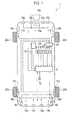
- a vehicle 1 is mounted with brake lamps 4a, 4b, an ignition switch 18 which provides commands to start and stop a driving force generation device including an engine and a motor, front obstacle detection sensors 13a to 13d, 19e which detect an obstacle approaching a front side PD of the vehicle 1, rear obstacle detection sensors 13e to 13h which detect an obstacle approaching a rear side of the vehicle 1, side obstacle detection sensors 19a to 19d which detect an obstacle approaching lateral sides of the vehicle 1, a driving force generation device 36 which generates a driving force for the vehicle, a braking force generation device 27, an accelerator pedal manipulation reaction force generation device 30, an alarm device 33 which alerts a driver that an obstacle is approaching, and a vehicle control device 2 (control unit) which controls the overall vehicle 1.
- the vehicle control device 2 corresponds to a control unit of the travel control device according to the embodiment.
- the front obstacle detection sensors 13a to 13d are installed for example in a front bumper of the vehicle 1, and the rear obstacle detection sensors 13e to 13h are installed for example in a rear bumper of the vehicle 1.
- Sonar detectors which use ultrasonic waves to detect an obstacle entering a region relatively in the vicinity of the vehicle 1 and a distance to the obstacle can be used as the front obstacle detection sensors 13a to 13d and the rear obstacle detection sensors 13e to 13h.
- the side obstacle detection sensors 19a to 19d are arranged respectively one on each of left and right fenders of the vehicle 1 on the front side PD and the rear side, and the front obstacle detection sensor 19e is installed for example in the front bumper of the vehicle 1.
- the vehicle control device 2 is configured by a processing unit such as an ECU (Engine Control Unit), and a CPU in the processing unit executes a previously stored computer program thereby to control operation of the overall vehicle 1.
- a processing unit such as an ECU (Engine Control Unit)
- a CPU in the processing unit executes a previously stored computer program thereby to control operation of the overall vehicle 1.
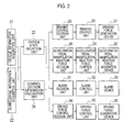
- the travel control device includes a vehicle information acquisition unit 21 which acquires information on the vehicle 1, a surrounding information acquisition unit 22 which acquires information on the surroundings of the vehicle, a system state selection unit 23, a control decision information calculation unit 24, and a warning device which issues a warning to an obstacle detected by the surrounding information acquisition unit 22.
- the warning device includes a braking force generation system (25 to 27) which generates a braking force to give the warning of the approach of the obstacle, an accelerator pedal manipulation reaction force generation system (28 to 30) which generates an accelerator pedal manipulation reaction force to give the warning of the approach of the obstacle, an alarm system (31 to 33) which gives an alarm to the driver to give the warning of the approach of the obstacle, and a driving force control system (34 to 36) which performs driving force control to give the warning of the approach of the obstacle.
- a braking force generation system 25 to 27
- an accelerator pedal manipulation reaction force generation system 28 to 30
- an alarm system 31 to 33
- a driving force control system 34 to 36
- the vehicle information acquisition unit 21 includes wheel speed sensors 11 a to 11d installed on wheels 20a to 20d, respectively, of the vehicle 1, an accelerator opening detection unit 5 installed on an accelerator pedal of the vehicle 1, a brake pedal position detection unit 6 which detects the position of a brake pedal of the vehicle 1, a shift position detection unit 9 (or a rearward movement preparation detection unit) which detects the shift position of the vehicle 1, an SW operation recognition unit 3 which detects the state of an on-off switch for the travel control device, a steering sensor 10 which detects a steering angle of a steering wheel of the vehicle 1, and an acceleration/deceleration sensor 12 which detects acceleration or deceleration of the vehicle 1.
- the wheel speed sensors 11a to 11d detect rotation speeds of the wheels 20a to 20d, respectively, of the vehicle 1.
- a vehicle speed calculation unit 40 calculates a vehicle speed (or a wheel speed) from the rotation speeds of the wheels 20a to 20d, taking into account a radius of rotation of the wheels 20a to 20d. Further, the vehicle speed calculation unit 40 calculates a travel distance by integrating the vehicle speed.
- the brake pedal position detection unit 6 detects whether or not the driver is depressing the brake pedal, and detects the amount of depression of the brake pedal.
- the shift position detection unit 9 detects the state of the shift position in order to detect the present state of a transmission.
- An example of detection of the vehicle 1 preparing to move rearward includes detection of a rearward movement (R) position by the shift position detection unit 9.
- the SW operation recognition unit 3 detects the switch state of the travel control device and the switch state of the ignition switch 18.
- a steering angle calculation unit 41 performs filtering processing on the steering angle of the steering wheel detected by the steering sensor 10, as needed.
- An acceleration/deceleration calculation unit 42 performs filtering processing on the acceleration or deceleration of the vehicle 1 detected by the acceleration/deceleration sensor 12, as needed.
- a vehicle information output unit 43 transfers the wheel speed of the vehicle 1, an accelerator opening, the position of the brake pedal, the shift position, the state of the on-off switch for the travel control device, the steering angle of the steering wheel and the acceleration or deceleration, as vehicle information, to the system state selection unit 23 or the control decision information calculation unit 24.
- the vehicle speed calculation unit 40, the steering angle calculation unit 41, the acceleration/deceleration calculation unit 42 and the vehicle information output unit 43 can be configured as a portion of the vehicle control device 2 of Fig. 1 .
- a processing unit which is different from the vehicle control device 2 is prepared, and a CPU in the processing unit executes a previously stored computer program. This may implement operation of the vehicle speed calculation unit 40, the steering angle calculation unit 41, the acceleration/deceleration calculation unit 42 and the vehicle information output unit 43.
- the surrounding information acquisition unit 22 includes the front obstacle detection sensors 13a to 13d, 19e, the rear obstacle detection sensors 13e to 13h, and the side obstacle detection sensors 19a to 19d, which are installed on the front, rear and lateral sides of the vehicle 1 illustrated in Fig. 1 so as to be configured as a surrounding obstacle detection sensor 37.
- a relative distance calculation unit 39 performs filtering processing on a value of a distance from an obstacle detected by the surrounding obstacle detection sensor 37, as needed.
- a relative speed estimation unit 38 estimates a relative speed with respect to the obstacle from the distance to the obstacle.
- the sign of the relative speed is such that a positive sign indicates a direction in which the obstacle approaches the vehicle 1 and a negative sign indicates a direction in which the obstacle moves away from the vehicle 1.
- the relative speed estimation unit 38 calculates the time (or approach time) required for the obstacle to approach the vehicle 1 from the distance to the obstacle and the relative speed detected by the side obstacle detection sensors 19a to 19d.
- the approach time may be determined for example by obtaining TTC (Time-To-Collision) by dividing the distance to the obstacle by the relative speed.
- a presence-or-absence-of-obstacle decision unit 44 outputs a signal indicating whether or not the surrounding obstacle detection sensor 37 has detected the obstacle.
- a surrounding information output unit 45 transfers the presence or absence of a possible obstacle which may be present at the front side PD, the rear side and the lateral sides of the vehicle 1, the distance to the obstacle and the relative speed, and the approach time and a direction or angle of detection of the obstacle to be described later, as surrounding information, to the system state selection unit 23 or the control decision information calculation unit 24.
- the relative distance calculation unit 39, the relative speed estimation unit 38, the presence-or-absence-of-obstacle decision unit 44 and the surrounding information output unit 45 can be configured as a portion of the vehicle control device 2 of Fig. 1 .
- a processing unit which is different from the vehicle control device 2 is prepared, and a CPU in the processing unit executes a previously stored computer program. This may implement operation of the relative distance calculation unit 39, the relative speed estimation unit 38, the presence-or-absence-of-obstacle decision unit 44 and the surrounding information output unit 45.
- the system state selection unit 23 determines whether to set the system state to the on or off state, based on the state of the on-off switch for the travel control device detected by the SW operation recognition unit 3.
- the side obstacle detection sensor 19c installed on a rear fender of the vehicle 1 on the left side thereof toward the rear thereof can detect a vehicle 60a, 60b entering a sector-shaped region (or the lateral side detection region) with a predetermined angle, including the lateral side of the vehicle 1, and ranging from the lateral side to the rear side of the vehicle 1, centered about the side obstacle detection sensor 19c.
- the side obstacle detection sensor 19c may divide the lateral side detection region into plural detection angle areas KR1 to KR7, and detect, for each of the plural detection angle areas KR1 to KR7, an obstacle entering the detection angle area and a distance to the obstacle. Which of the detection angle areas KR1 to KR7 the obstacle is detected in can be determined for example by horizontally scanning electromagnetic waves in the lateral side detection region. The number of areas divided is not limited to seven but may be set less or more than seven. However, the side obstacle detection sensor 19c is not so limited but does not necessarily have to divide the lateral side detection region into the plural detection angle areas KR1 to KR7. In this case, the angle or direction of detection of the detected obstacle is not detected.
- the other side obstacle detection sensors 19a, 19b, 19d are the same as the side obstacle detection sensor 19c.
- the laterals or sides of the vehicle refers to sides in a direction perpendicular to the parking direction PD of the vehicle 1
- Fig. 9 illustrates a left side as the lateral side.
- the rear of the vehicle refers to a side in a direction rotated 180° with respect to the parking direction PD of the vehicle 1.
- the boundary of the plural detection angle areas KR1 to KR7 on the rear side is located on the lateral side of a half-line extending rearward from the side obstacle detection sensor 19c.
- the rear obstacle detection sensors 13e to 13h can detect the obstacle entering rear detection areas MR1 to KR4, respectively, extending rearward from the rear bumper of the vehicle 1.
- the rear obstacle detection sensors 13e to 13h are in a one-to-one correspondence with the rear detection areas MR1 to KR4.
- the adjacent rear detection areas MR1 to KR4 partially overlap one another. Also, some of the rear detection areas MR1 to KR4, on the left lateral side, overlap a portion of the lateral side detection region of the side obstacle detection sensor 19c. Also on the right lateral side, some of the rear detection areas MR1 to KR4 overlap a portion of the lateral side detection region of the side obstacle detection sensor 19d, although not illustrated.
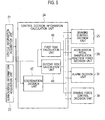
- the control decision information calculation unit 24 includes a coordination decision unit 47 which determines whether or not to coordinate results detected by the side obstacle detection sensors 19a to 19d with results detected by the rear obstacle detection sensors 13e to 13h, a first risk calculation unit 48 which calculates a first risk (or a first warning threshold) as a criterion of judgment of warning, and a second risk calculation unit 49 which calculates a second risk (or a second warning threshold) as a criterion of judgment of warning.
- a result determined by the coordination decision unit 47 and results calculated by the first risk calculation unit 48 and the second risk calculation unit 49 are transmitted to a braking control decision unit 25, an accelerator pedal manipulation reaction force decision unit 28, an alarm decision unit 31, and a driving force control decision unit 34.
- the first risk calculation unit 48 first calculates a base value of the first risk.
- the base value of the first risk is used as a reference value to determine whether or not to provide warning based on a distance to an obstacle detected by the rear obstacle detection sensors 13e to 13h.
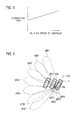
- the base value of the first risk is a distance which varies according to the vehicle speed. For example, as illustrated in Fig. 7 , the higher vehicle speed leads to the larger base value of the first risk.
- the base value of the first risk may be offset to take on a predetermined value. Also, the base value of the first risk may be changed according to the approach time calculated by the relative speed estimation unit 38.
- the first risk calculation unit 48 may calculate the base value of the first risk from the vehicle speed and the approach time by referring to data indicating a relationship between the vehicle speed and the base value of the first risk illustrated in Fig. 7 , and data indicating a relationship between the approach time and the base value of the first risk.
- the first risk calculation unit 48 calculates the first risk for each warning control from the base value of the first risk by using a coefficient for each warning control.
- the first risk for each warning control can be calculated by varying weights for each warning control by multiplying the base value by a coefficient R1_K1 for braking control, multiplying the base value by a coefficient R1_K2 for accelerator pedal manipulation reaction force control, multiplying the base value by a coefficient R1_K3 for alarm control, and multiplying the base value by a coefficient R1_K4 for driving force control.
- the coefficients are set to values which lie between 0 and 1 inclusive, and are such that the following relationship is established: R1_K1 ⁇ R1_K2 ⁇ R1_K4 ⁇ R1_K3. This enables weighting such that the alarm, the driving force control, the accelerator pedal manipulation reaction force control, and the braking control are performed in this order.
- the second risk calculation unit 49 first calculates a base value of the second risk.
- the base value of the second risk includes a base value of the second risk (the distance) and a base value of the second risk (the approach time).
- the base value of the second risk (the distance) is used as a reference value to determine whether or not to provide warning based on a distance to an obstacle detected by the side obstacle detection sensors 19a to 19d.
- the base value of the second risk (the approach time) is used as a reference value to determine whether or not to provide warning based on the approach time calculated by the relative speed estimation unit 38.
- the base value of the second risk (the distance) varies according to the vehicle speed.
- the second risk calculation unit 49 can calculate the base value of the second risk (the distance) from the vehicle speed by referring to data indicating a relationship between the vehicle speed and the base value of the second risk (the distance).
- the base value of the second risk (the distance) may be set to a different value from the base value of the first risk. In this case, it is desirable that the base value of the second risk (the distance) be set to a larger value than the base value of the first risk.
- the base value of the second risk (the distance) may be offset to take on a predetermined value.
- the base value of the second risk (the distance) may be changed according to the approach time calculated by the relative speed estimation unit 38.
- the second risk calculation unit 49 calculates the second risk (the distance) and the second risk (the approach time) for each warning control from the base value of the second risk (the distance) and the base value of the second risk (the approach time) by using a coefficient for each warning control.
- the second risk (the distance) and the second risk (the approach time) for each control are calculated by varying weights for each control by multiplying the base value by a coefficient R2_K1 for braking control, multiplying the base value by a coefficient R2_K2 for accelerator pedal manipulation reaction force, multiplying the base value by a coefficient R2_K3 for alarm control, and multiplying the base value by a coefficient R2_K4 for driving force control.
- the coefficients are set to values which lie between 0 and 1 inclusive, and are such that the following relationship is established: R2_K1 ⁇ R2_K2 ⁇ R2_K4 ⁇ R2_K3. This enables weighting such that the alarm, the driving force control, the accelerator pedal manipulation reaction force control, and the braking control are performed in this order.
- the coordination decision unit 47 determines whether or not to coordinate the side obstacle detection sensors 19a to 19c with the rear obstacle detection sensors 13e to 13h, and, if a decision is made to coordinate, the coordination decision unit 47 makes a correction on the first risk. Specifically, if the shift position detection unit 9 determines that the shift position of the vehicle 1 is located in the R (rearward movement) position and a para-meter based on the distance to the obstacle detected by the side obstacle detection sensors 19a to 19c is greater than the second warning threshold, the coordination decision unit 47 increases the first risk (or the first warning threshold) until a hold time elapses after all the side obstacle detection sensors 19a to 19c become unable to detect the obstacle.
- the rear obstacle detection sensors 13e to 13h can early detect the obstacle which is no longer detectable with the side obstacle detection sensors 19a to 19c.
- the "para-meter based on the distance to the obstacle” includes the distance to the obstacle detected by the side obstacle detection sensors 19a to 19c, and the approach time calculated by the relative speed estimation unit 38.
- the second risk the distance
- the second risk the approach time
- the second risk the approach time
- the braking force generation system (25 to 27) includes the braking control decision unit 25 which determines whether or not to perform braking force control to give a warning of the approach of an obstacle, a braking control unit 26, and the braking force generation device 27 which performs the braking force control to give the warning of the approach of the obstacle under control by the braking control unit 26.
- the accelerator pedal manipulation reaction force generation system (28 to 30) includes the accelerator pedal manipulation reaction force decision unit 28 which determines whether or not to perform accelerator pedal manipulation reaction force control to give the warning of the approach of the obstacle, an accelerator pedal manipulation reaction force control unit 29, and the accelerator pedal manipulation reaction force generation device 30 which performs the accelerator pedal manipulation reaction force control to give the warning of the approach of the obstacle under control by the accelerator pedal manipulation reaction force control unit 29.
- the alarm system (31 to 33) includes the alarm decision unit 31 which determines whether or not to give an alarm to the driver to give the warning of the approach of the obstacle, an alarm control unit 32, and the alarm device 33 which gives the alarm to the driver to give the warning of the approach of the obstacle under control by the alarm control unit 32.
- the driving force generation system (34 to 36) includes the driving force control decision unit 34 which determines whether or not to perform driving force control to give the warning of the approach of the obstacle, a driving force control unit 35, and the driving force generation device 36 which performs the driving force control to give the warning of the approach of the obstacle under control by the driving force control unit 35.
- the first risk, the second risk (the distance) and the second risk (the approach time) calculated for each control are transmitted to the braking control decision unit 25, the accelerator pedal manipulation reaction force decision unit 28, the alarm decision unit 31, and the driving force control decision unit 34.
- the braking control decision unit 25 determines to generate a braking force to give the warning of the approach of the obstacle, when any of conditions A01 to A03 described below is established.
- the distance to the obstacle detected by the rear obstacle detection sensors 13e to 13h is referred to as a "rear sensor detected distance”
- the distance to the obstacle detected by the side obstacle detection sensors 19a to 19d is referred to as a “side sensor detected distance”
- the approach time calculated by the relative speed estimation unit 38 is referred to as "side sensor approach time.”
- the first risk, the second risk (a distance value) and the second risk (the approach time) obtained by multiplying their base values by the coefficient R1_K1 or R2_K1 for the braking control are referred to as the first risk for braking, the second risk (the distance value) for braking and the second risk (the approach time) for braking, respectively.
- the braking control unit 26 When the braking control decision unit 25 determines to activate warning by braking, the braking control unit 26 increases a brake pressure at a predetermined rate of change, and then, when a predetermined target brake pressure is reached, the braking control unit 26 maintains the brake pressure as it is. When hold time reaches a predetermined time (for example, 0.8 seconds), or when a predetermined time elapses after the vehicle speed has become equal to 0, the brake pressure is reduced to 0 at a predetermined rate of change.
- the predetermined rate of change and the predetermined target brake pressure may both be changed according to the vehicle speed or the distance to the obstacle.
- the braking force generation device 27 controls actual brake pressures on the wheels 20a to 20d so as to achieve the target brake pressure calculated by the braking control unit 26.
- the accelerator pedal manipulation reaction force decision unit 28 determines to generate an accelerator pedal manipulation reaction force to give the warning of the approach of the obstacle, when any of conditions A04 to A06 described below is established.
- the first risk, the second risk (the distance value) and the second risk (the approach time) obtained by multiplying their base values by the coefficient R1_K2 or R2_K2 for the accelerator pedal manipulation reaction force are referred to as the first risk for APD, the second risk (the distance value) for APD and the second risk (the approach time) for APD, respectively.
- the accelerator pedal manipulation reaction force control unit 29 increases a reaction force command value at a predetermined rate of change, and then, when a predetermined reaction force command value is reached, the accelerator pedal manipulation reaction force control unit 29 maintains the reaction force command value as it is.
- the reaction force command value is reduced to 0 at a predetermined rate of change.
- the predetermined rate of change and the predetermined reaction force command value may both be changed according to the vehicle speed or the distance to the obstacle.
- the accelerator pedal manipulation reaction force generation device 30 controls the manipulation reaction force of the accelerator pedal so as to achieve the reaction force command value calculated by the accelerator pedal manipulation reaction force control unit 29.
- the alarm decision unit 31 determines to give an alarm by a sound or a buzzer or the like to give the warning of the approach of the obstacle, when any of conditions A07 to A09 described below is established.
- the first risk, the second risk (the distance value) and the second risk (the approach time) obtained by multiplying their base values by the coefficient R1_K3 or R2_K3 for the alarm are referred to as the first risk for alarm, the second risk (the distance value) for alarm and the second risk (the approach time) for alarm, respectively.
- the alarm control unit 32 When the alarm decision unit 31 determines to give the alarm, the alarm control unit 32 repeatedly turns on and off a buzzer driving signal for a predetermined time.
- the alarm device 33 gives the alarm based on the buzzer driving signal calculated by the alarm control unit 32. For example, a predetermined beep is repeatedly emitted. Alternatively, the alarm may be continuously sounded while any of the above-described conditions is satisfied. Further, simultaneously with the alarm, a light emitter such as an indicator installed in a meter may flash on and off.
- the driving force control decision unit 34 determines to perform the driving force control to give the warning of the approach of the obstacle, when any of conditions A10 to A12 described below is established.
- the first risk, the second risk (the distance value) and the second risk (the approach time) obtained by multiplying their base values by the coefficient R1_K4 or R2_K4 for the driving force are referred to as the first risk for driving force, the second risk (the distance value) for driving force and the second risk (the approach time) for driving force, respectively.
- the driving force control unit 35 increases the amount of reduction in the accelerator opening at a predetermined rate of change.
- the amount of reduction in the accelerator opening reaches a predetermined value, the amount of reduction is maintained as it is.
- the amount of reduction in the accelerator opening is reduced to 0.
- the final throttle opening of the engine has a value obtained by subtracting the amount of reduction in the accelerator opening calculated by the driving force control unit 35 from the accelerator opening operated by the driver.
- the predetermined rate of change and the predetermined value of the amount of reduction in the accelerator opening may both be changed according to the vehicle speed or the distance to the obstacle.
- the driving force generation device 36 controls engine power based on the final throttle opening of the engine calculated by the driving force control unit 35.
- warning is determined based on the obstacle's approach time, and thereby, the warning of an obstacle can be provided when the obstacle is approaching the vehicle 1 at high speed even if there is a great distance to the obstacle detected by the rear obstacle detection sensors 13e to 13h or the side obstacle detection sensors 19a to 19d. This enables recognizing a potential danger of the obstacle, thus providing the properly timed warning.
- the system state selection unit 23, the control decision information calculation unit 24, the braking control decision unit 25, the braking control unit 26, the accelerator pedal manipulation reaction force decision unit 28, the accelerator pedal manipulation reaction force control unit 29, the alarm decision unit 31, the alarm control unit 32, the driving force control decision unit 34 and the driving force control unit 35, illustrated in Fig. 2 can be configured as a portion of the vehicle control device 2 of Fig. 1 .
- a processing unit which is different from the vehicle control device 2 is prepared, and a CPU in the processing unit executes a previously stored computer program.
- This may implement operation of the system state selection unit 23, the control decision information calculation unit 24, the braking control decision unit 25, the braking control unit 26, the accelerator pedal manipulation reaction force decision unit 28, the accelerator pedal manipulation reaction force control unit 29, the alarm decision unit 31, the alarm control unit 32, the driving force control decision unit 34 and the driving force control unit 35.
- a control unit of the travel control device having the above-described configuration executes travel control operation described below, thereby enabling properly timed warning about an obstacle detected by the rear obstacle detection sensors 13e to 13h or the side obstacle detection sensors 19a to 19d.
- Description will be given below with reference to a flowchart of Fig. 6 with regard to how the travel control device operates when executing the travel control operation.
- the flowchart of Fig. 6 starts at the time when the system state selection unit 23 determines that the on-off switch for the travel control device is in the on state and the shift position detection unit 9 determines that the shift position of the vehicle 1 is located in the R (rearward movement) position, and the travel control operation goes to step S1 to perform processing. Then, the travel control operation is repeatedly executed so long as the on-off switch for the travel control device is in the on state and the shift position of the vehicle 1 is located in the R position.
- the timing of start of the travel control operation is not limited to the above-described condition; besides the above-described condition, a condition such for example as where the vehicle speed is equal to or less than a predetermined value or the steering angle of the steering wheel is equal to or less than a predetermined value may be added.
- the first risk calculation unit 48 and the second risk calculation unit 49 determine the first risk or the second risk for each warning control. Specifically, the first risk for braking, the second risk (the distance value) for braking, the second risk (the approach time) for braking, the first risk for APD, the second risk (the distance value) for APD, the second risk (the approach time) for APD, the first risk for alarm, the second risk (the distance value) for alarm, the second risk (the approach time) for alarm, the first risk for driving force, the second risk (the distance value) for driving force, and the second risk (the approach time) for driving force are calculated.
- the coordination decision unit 47 determines whether or not to coordinate the side obstacle detection sensors 19a to 19c with the rear obstacle detection sensors 13e to 13h. If a decision is made to coordinate, the first risk calculated at step S1 is corrected to a large value so that the rear obstacle detection sensors 13e to 13h can early detect the obstacle which is no longer detectable with the side obstacle detection sensors 19a to 19c.
- a vehicle 61 (or an obstacle) running rearward of the vehicle 1 enters the lateral side detection region KR1 to KR7 and is detected by the side obstacle detection sensor 19c. After that, the vehicle 61 goes out of the lateral side detection region KR1 to KR7, and thus the side obstacle detection sensor 19c becomes unable to detect the obstacle. Thus, if the temporarily detected obstacle goes out of the lateral side detection region KR1 to KR7 and thus becomes undetected, or equivalently, the side obstacle detection sensor 19c loses track of the obstacle (YES at step S2), it is desirable that an early warning of the obstacle be then issued by using the results detected by the rear obstacle detection sensors 13e to 13h.
- the coordination decision unit 47 corrects the first risk so as to increase the first risk until the hold time elapses after the side obstacle detection sensor 19c becomes unable to detect the obstacle (at step S3).
- the rear obstacle detection sensors 13e to 13h can be coordinated for the obstacle lost by the side obstacle detection sensor 19c. This enables advancing the timing of warning based on the results detected by the rear obstacle detection sensors 13e to 13h, thus giving the early warning of the obstacle to the driver.
- the corrected first risk is restored to its value before the correction. Meanwhile, if the obstacle is detected in the lateral side detection region KR1 to KR7 (NO at step S2), the first risk calculated at step S1 is not corrected.
- the side obstacle detection sensor 19c when the side obstacle detection sensor 19c becomes unable to detect the obstacle, it does not matter whether or not the rear obstacle detection sensors 13e to 13h detect the obstacle. In other words, at the instant when the rear obstacle detection sensors 13e to 13h lose track of the obstacle, it does not matter whether or not the obstacle enters any of the rear detection areas MR1 to MR4 of the rear obstacle detection sensors 13e to 13h. If the distance to the obstacle is greater than the first risk at the instant when the rear obstacle detection sensors 13e to 13h lose track of the obstacle, the timing of warning based on the results detected by the rear obstacle detection sensors 13e to 13h can be advanced by increasing the first risk.
- step S4 the braking control decision unit 25, the accelerator pedal manipulation reaction force decision unit 28, the alarm decision unit 31, and the driving force control decision unit 34 determine whether or not to give a warning of the approach of the obstacle in accordance with the above-described conditions A01 to A12. Only when a decision is made to give the warning (YES at step S4), processing is performed at step S5 to give the warning of the approach of the obstacle.
- any one or more of the side obstacle detection sensors 19a to 19d may replace the side obstacle detection sensor 19c for implementation.
- a first example of a method for correcting the first risk at step S3 is to multiply the base value of the first risk by a correction gain which is a number equal to or more than 1.
- the timing of warning can be uniformly advanced by correcting the first risk to a large value by multiplying the first risk by the number (for example, 2) equal to or more than 1, as the correction gain (or a fixed value).
- the correction gain may be changed according to the relative speed to the obstacle at a time when all the side obstacle detection sensors 19a to 19d become unable to detect the obstacle. In this case, it is desirable that the correction gain be set larger as the relative speed to the obstacle becomes higher, as illustrated in Fig. 8 . The higher relative speed to the obstacle can yield the earlier timing of warning, thus enabling proper warning control.
- a second example of the method for correcting the first risk at step S3 is to set the base value of the first risk to a given value, for example 2 m, regardless of the vehicle speed illustrated in Fig. 7 .
- the base value of the first risk may be increased only for the rear obstacle detection sensors 13f, 13g in a central portion among the plural rear obstacle detection sensors 13e to 13h, according to the shape of the vehicle 1.
- the hold time may be determined based on the distance (D) to the obstacle and the relative speed (VK) with respect to the obstacle at a time when the side obstacle detection sensor 19c becomes unable to detect the obstacle, as illustrated in Fig. 10 .
- the hold time (TK) can be calculated according to Equation (1).
- FST indicates an offset value taking into account the overall width of the vehicle 1, and is set to 2.5 m, for example.
- TK D + FST / VK
- a shorter one of a preset time and the time determined based on the distance (D) to the obstacle and the relative speed (VK) with respect to the obstacle at a time when the side obstacle detection sensor 19c becomes unable to detect the obstacle may be used as the hold time.
- the hold time becomes shorter, thus enabling earlier warning.
- the hold time is not limited to being determined by performing calculation using Equation (1), and the preset time may be used as the hold time.
- a decision may be made to coordinate thereby to correct the first risk.
- the "side warning threshold” is set to 7 m, for example.
- a decision may be made to coordinate thereby to correct the first risk.
- the reason is that, if the rear obstacle detection sensors 13e to 13h detect the obstacle when the side obstacle detection sensor 19c becomes unable to detect the obstacle, proper warning control can be performed based on the results detected by the rear obstacle detection sensors 13e to 13h, even without correcting the first risk.
- the first risk (or the first warning threshold) is increased until the hold time elapses after all the side obstacle detection sensors 19a to 19d become unable to detect the obstacle, and thereby, early warning can be provided based on the results detected by the rear obstacle detection sensors 13e to 13h.
- a delay in the timing of warning or unwarned conditions can be suppressed.
- the hold time is determined based on the distance (D) to the obstacle and the relative speed (VK) to the obstacle at a time when all the side obstacle detection sensors 19a to 19d become unable to detect the obstacle.
- the rear obstacle detection sensors 13e to 13h detect, with improved accuracy, the obstacle which is no longer detectable with the side obstacle detection sensors 19a to 19d, and thus, a delay in warning or unwarned conditions can be suppressed.
- the first risk is increased thereby to exclude the obstacle which is present so far away as to need no early warning and is no longer detectable, thus enabling suppression of unnecessary warning control.
- the first risk may be increased. If the rear obstacle detection sensors 13e to 13h do not detect the obstacle when the side obstacle detection sensors 19a to 19d becomes unable to detect the obstacle, obstacle detection information cannot be handed over from the side obstacle detection sensors 19a to 19d to the rear obstacle detection sensors 13e to 13h. In such a case, therefore, the first risk is increased until the hold time elapses, and thereby, a delay in warning or unwarned conditions can be suppressed.
- the shorter one of the preset time and the time determined based on the distance to the obstacle and the relative speed to the obstacle at the time when all the side obstacle detection sensors 19a to 19d become unable to detect the obstacle may be used as the hold time. Thereby, the hold time becomes shorter, thus enabling earlier warning.
- the first risk may be set larger as the relative speed to the obstacle at the time when all the side obstacle detection sensors 19a to 19d become unable to detect the obstacle becomes higher. Thereby, the higher relative speed can yield the earlier timing of warning, thus enabling suppression of a delay in warning or unwarned conditions.
- the first risk may be corrected for each of the rear obstacle detection sensors 13e to 13h, according to the state of detection that the rear obstacle detection sensors 13e to 13h obtain when all the side obstacle detection sensors 19a to 19d become unable to detect the obstacle. If at least one of the rear obstacle detection sensors 13e to 13h detects the obstacle when all the side obstacle detection sensors 19a to 19d become unable to detect the obstacle, the first risk calculation unit 48 increases the first risk for the other rear obstacle detection sensors, exclusive of the rear obstacle detection sensor detecting the obstacle. Early warning control can be performed by using the rest of the rear obstacle detection sensors 13e to 13h, exclusive of the detecting one of the rear obstacle detection sensors 13e to 13h detecting the obstacle when all the side obstacle detection sensors 19a to 19d become unable to detect the obstacle. Also, erroneous advance of the timing of warning is suppressed.
- results detected by the rear obstacle detection sensor 13e arranged on the leftmost side may be ignored.
- results detected by the rear obstacle detection sensor 13e arranged on the leftmost side and the rear obstacle detection sensor 13f arranged at the second position from the left may be ignored.
- the first risk may be set to 0 for at least one of the rear obstacle detection sensors 13e to 13h which detects the obstacle at the predetermined distance (for example, 40 cm) or shorter when all the side obstacle detection sensors 19a to 19d become unable to detect the obstacle. This avoids warning based on results detected by the detecting one of the rear obstacle detection sensors 13e to 13h detecting the obstacle at the predetermined distance (for example, 40 cm) or shorter.
- early warning can be provided about an obstacle detected by the rear obstacle detection sensors 13e to 13h.
- a delay in the timing of warning or unwarned conditions can be suppressed. Therefore, the present invention has industrial applicability.
Landscapes
- Engineering & Computer Science (AREA)
- Remote Sensing (AREA)
- Radar, Positioning & Navigation (AREA)
- Physics & Mathematics (AREA)
- General Physics & Mathematics (AREA)
- Computer Networks & Wireless Communication (AREA)
- Mechanical Engineering (AREA)
- Human Computer Interaction (AREA)
- Acoustics & Sound (AREA)
- Electromagnetism (AREA)
- Control Of Driving Devices And Active Controlling Of Vehicle (AREA)
- Traffic Control Systems (AREA)
- Measurement Of Velocity Or Position Using Acoustic Or Ultrasonic Waves (AREA)
- Regulating Braking Force (AREA)
Abstract
Description
- The present invention relates to a travel control device and a travel control method.
- A technique for a vehicle to detect an obstacle approaching the surroundings of the vehicle by using an obstacle sensor mounted on the vehicle has heretofore been known. (Refer to Patent Literature 1, for example.)
- In Patent Literature 1, a rear portion of the vehicle is mounted with an ultrasonic sensor having a detection region rearward of the vehicle, and an ultrasonic sensor having a detection region laterally rearward of the vehicle. The ultrasonic sensor having the detection region laterally rearward of the vehicle has a detectable region in which an obstacle located even far away in the rear is detectable, whereas the ultrasonic sensor having the detection region rearward of the vehicle can detect the obstacle only in the vicinity of the vehicle. Therefore, an undetectable region in which any obstacle is undetectable is present far away right behind the vehicle.
- Patent Literature 1: Japanese Patent Application Publication No.
2009-280109 - Even if an obstacle is detected, the ultrasonic sensor having the detection region laterally rearward of the vehicle does not issue a warning unless a distance to the obstacle or approach time is less than a warning threshold. When the obstacle moves from there to the undetectable region rearward of the vehicle, neither of the ultrasonic sensors can detect the obstacle until the ultrasonic sensor having the detection region rearward of the vehicle detects the obstacle, and therefore, a delay in detection of the obstacle may occur.
- The present invention has been made in view of the foregoing problem. An object of the present invention is to provide a travel control device and a travel control method which properly detect an obstacle even if the obstacle enters an undetectable region, thereby suppressing a delay in the timing of warning or unwarned conditions when a vehicle moves rearward.
- A travel control device according to a first aspect of the present invention includes a rear obstacle detection unit, a side obstacle detection unit, a rearward movement preparation detection unit, a warning unit, and a control unit. The rear obstacle detection unit detects an obstacle entering an area rearward of a vehicle, and a distance to the obstacle. The side obstacle detection unit detects an obstacle entering a predetermined lateral side detection region including an area laterally rearward of the vehicle, and a distance to the obstacle. The rearward movement preparation detection unit detects the vehicle preparing to move rearward. The warning unit provides warning about the obstacle detected by the rear obstacle detection unit or the side obstacle detection unit. The control unit controls the warning unit so that the warning is provided if the distance to the obstacle detected by the rear obstacle detection unit is equal to or less than a first warning threshold, or if a parameter based on the distance to the obstacle detected by the side obstacle detection unit is equal to or less than a second warning threshold. If the rearward movement preparation detection unit detects the vehicle preparing to move rearward and the para-meter based on the distance to the obstacle detected by the side obstacle detection unit is greater than the second warning threshold, the control unit increases the first warning threshold until a hold time elapses after the side obstacle detection unit becomes unable to detect the obstacle.
- A travel control method according to a second aspect of the present invention using a travel control device including the rear obstacle detection unit, the side obstacle detection unit, the rearward movement preparation detection unit, and the warning unit includes controlling the warning unit so that the warning is provided if the distance to the obstacle detected by the rear obstacle detection unit is equal to or less than a first warning threshold, or if a parameter based on the distance to the obstacle detected by the side obstacle detection unit is equal to or less than a second warning threshold; and increasing the first warning threshold until a hold time elapses after the side obstacle detection unit becomes unable to detect the obstacle, if the rearward movement preparation detection unit detects the vehicle preparing to move rearward and the para-meter based on the distance to the obstacle detected by the side obstacle detection unit is greater than the second warning threshold.
-
- [
Fig. 1] Fig. 1 is a schematic view illustrating an example of a vehicle layout of a travel control device according to an embodiment. - [
Fig. 2] Fig. 2 is a block diagram illustrating a configuration of the travel control device according to the embodiment. - [
Fig. 3] Fig. 3 is a block diagram illustrating a specific example of a configuration of a vehicleinformation acquisition unit 21 ofFig. 2 . - [
Fig. 4] Fig. 4 is a block diagram illustrating a specific example of a configuration of a surroundinginformation acquisition unit 22 ofFig. 2 . - [
Fig. 5] Fig. 5 is a block diagram illustrating a specific example of a configuration of a control decisioninformation calculation unit 24 ofFig. 2 . - [
Fig. 6] Fig. 6 is a flowchart illustrating how the travel control device operates when executing travel control operation. - [
Fig. 7] Fig. 7 is a graph showing an example of a relationship between a vehicle speed and a first risk (or a first warning threshold). - [
Fig. 8] Fig. 8 is a graph showing an example of a relationship between a relative speed to an obstacle and a correction gain. - [
Fig. 9] Fig. 9 is a plan view illustrating a lateral side detection region KR1 to KR7 in which a sideobstacle detection sensor 19c can detect the obstacle, and rear detection areas MR1 to KR4 in which rearobstacle detection sensors 13e to 13h can detect the obstacle, respectively. - [
Fig. 10] Fig. 10 is a plan view illustrating avehicle 61 as running, rearward in the vicinity of a vehicle 1, in a direction AD oblique relative to a parking direction PD of the vehicle 1. - An embodiment of the present invention will be described below with reference to the drawings. In the disclosures of the drawings, the same portions are designated by the same reference characters.
- Description will be given with reference to
Fig. 1 with regard to an example of a vehicle layout of a travel control device according to an embodiment. A vehicle 1 is mounted withbrake lamps ignition switch 18 which provides commands to start and stop a driving force generation device including an engine and a motor, frontobstacle detection sensors 13a to 13d, 19e which detect an obstacle approaching a front side PD of the vehicle 1, rearobstacle detection sensors 13e to 13h which detect an obstacle approaching a rear side of the vehicle 1, sideobstacle detection sensors 19a to 19d which detect an obstacle approaching lateral sides of the vehicle 1, a drivingforce generation device 36 which generates a driving force for the vehicle, a brakingforce generation device 27, an accelerator pedal manipulation reactionforce generation device 30, analarm device 33 which alerts a driver that an obstacle is approaching, and a vehicle control device 2 (control unit) which controls the overall vehicle 1. Incidentally, thevehicle control device 2 corresponds to a control unit of the travel control device according to the embodiment. - The front
obstacle detection sensors 13a to 13d are installed for example in a front bumper of the vehicle 1, and the rearobstacle detection sensors 13e to 13h are installed for example in a rear bumper of the vehicle 1. Sonar detectors which use ultrasonic waves to detect an obstacle entering a region relatively in the vicinity of the vehicle 1 and a distance to the obstacle can be used as the frontobstacle detection sensors 13a to 13d and the rearobstacle detection sensors 13e to 13h. The sideobstacle detection sensors 19a to 19d are arranged respectively one on each of left and right fenders of the vehicle 1 on the front side PD and the rear side, and the frontobstacle detection sensor 19e is installed for example in the front bumper of the vehicle 1. Radar detectors which use electromagnetic waves to detect an obstacle entering a region relatively far away from the vehicle 1 can be used as the sideobstacle detection sensors 19a to 19d and the frontobstacle detection sensor 19e. Therefore, a distance to which the sideobstacle detection sensors 19a to 19d and the frontobstacle detection sensor 19e can detect the obstacle is longer than a distance to which the frontobstacle detection sensors 13a to 13d and the rearobstacle detection sensors 13e to 13h can detect the obstacle. Thevehicle control device 2 is configured by a processing unit such as an ECU (Engine Control Unit), and a CPU in the processing unit executes a previously stored computer program thereby to control operation of the overall vehicle 1. - A configuration of the travel control device according to the embodiment will be described with reference to
Fig. 2 . The travel control device according to the embodiment includes a vehicleinformation acquisition unit 21 which acquires information on the vehicle 1, a surroundinginformation acquisition unit 22 which acquires information on the surroundings of the vehicle, a systemstate selection unit 23, a control decisioninformation calculation unit 24, and a warning device which issues a warning to an obstacle detected by the surroundinginformation acquisition unit 22. Here, the warning device includes a braking force generation system (25 to 27) which generates a braking force to give the warning of the approach of the obstacle, an accelerator pedal manipulation reaction force generation system (28 to 30) which generates an accelerator pedal manipulation reaction force to give the warning of the approach of the obstacle, an alarm system (31 to 33) which gives an alarm to the driver to give the warning of the approach of the obstacle, and a driving force control system (34 to 36) which performs driving force control to give the warning of the approach of the obstacle. - As illustrated in
Fig. 3 , the vehicleinformation acquisition unit 21 includeswheel speed sensors 11 a to 11d installed onwheels 20a to 20d, respectively, of the vehicle 1, an acceleratoropening detection unit 5 installed on an accelerator pedal of the vehicle 1, a brake pedal position detection unit 6 which detects the position of a brake pedal of the vehicle 1, a shift position detection unit 9 (or a rearward movement preparation detection unit) which detects the shift position of the vehicle 1, an SWoperation recognition unit 3 which detects the state of an on-off switch for the travel control device, asteering sensor 10 which detects a steering angle of a steering wheel of the vehicle 1, and an acceleration/deceleration sensor 12 which detects acceleration or deceleration of the vehicle 1. - The
wheel speed sensors 11a to 11d detect rotation speeds of thewheels 20a to 20d, respectively, of the vehicle 1. A vehiclespeed calculation unit 40 calculates a vehicle speed (or a wheel speed) from the rotation speeds of thewheels 20a to 20d, taking into account a radius of rotation of thewheels 20a to 20d. Further, the vehiclespeed calculation unit 40 calculates a travel distance by integrating the vehicle speed. The brake pedal position detection unit 6 detects whether or not the driver is depressing the brake pedal, and detects the amount of depression of the brake pedal. The shiftposition detection unit 9 detects the state of the shift position in order to detect the present state of a transmission. An example of detection of the vehicle 1 preparing to move rearward includes detection of a rearward movement (R) position by the shiftposition detection unit 9. The SWoperation recognition unit 3 detects the switch state of the travel control device and the switch state of theignition switch 18. A steeringangle calculation unit 41 performs filtering processing on the steering angle of the steering wheel detected by thesteering sensor 10, as needed. An acceleration/deceleration calculation unit 42 performs filtering processing on the acceleration or deceleration of the vehicle 1 detected by the acceleration/deceleration sensor 12, as needed. A vehicleinformation output unit 43 transfers the wheel speed of the vehicle 1, an accelerator opening, the position of the brake pedal, the shift position, the state of the on-off switch for the travel control device, the steering angle of the steering wheel and the acceleration or deceleration, as vehicle information, to the systemstate selection unit 23 or the control decisioninformation calculation unit 24. The vehiclespeed calculation unit 40, the steeringangle calculation unit 41, the acceleration/deceleration calculation unit 42 and the vehicleinformation output unit 43 can be configured as a portion of thevehicle control device 2 ofFig. 1 . Of course, a processing unit which is different from thevehicle control device 2 is prepared, and a CPU in the processing unit executes a previously stored computer program. This may implement operation of the vehiclespeed calculation unit 40, the steeringangle calculation unit 41, the acceleration/deceleration calculation unit 42 and the vehicleinformation output unit 43. - A detailed example of a configuration of the surrounding
information acquisition unit 22 will be described with reference toFig. 4 . The surroundinginformation acquisition unit 22 includes the frontobstacle detection sensors 13a to 13d, 19e, the rearobstacle detection sensors 13e to 13h, and the sideobstacle detection sensors 19a to 19d, which are installed on the front, rear and lateral sides of the vehicle 1 illustrated inFig. 1 so as to be configured as a surroundingobstacle detection sensor 37. A relativedistance calculation unit 39 performs filtering processing on a value of a distance from an obstacle detected by the surroundingobstacle detection sensor 37, as needed. A relativespeed estimation unit 38 estimates a relative speed with respect to the obstacle from the distance to the obstacle. The sign of the relative speed is such that a positive sign indicates a direction in which the obstacle approaches the vehicle 1 and a negative sign indicates a direction in which the obstacle moves away from the vehicle 1. Further, the relativespeed estimation unit 38 calculates the time (or approach time) required for the obstacle to approach the vehicle 1 from the distance to the obstacle and the relative speed detected by the sideobstacle detection sensors 19a to 19d. The approach time may be determined for example by obtaining TTC (Time-To-Collision) by dividing the distance to the obstacle by the relative speed. A presence-or-absence-of-obstacle decision unit 44 outputs a signal indicating whether or not the surroundingobstacle detection sensor 37 has detected the obstacle. A surroundinginformation output unit 45 transfers the presence or absence of a possible obstacle which may be present at the front side PD, the rear side and the lateral sides of the vehicle 1, the distance to the obstacle and the relative speed, and the approach time and a direction or angle of detection of the obstacle to be described later, as surrounding information, to the systemstate selection unit 23 or the control decisioninformation calculation unit 24. The relativedistance calculation unit 39, the relativespeed estimation unit 38, the presence-or-absence-of-obstacle decision unit 44 and the surroundinginformation output unit 45 can be configured as a portion of thevehicle control device 2 ofFig. 1 . Of course, a processing unit which is different from thevehicle control device 2 is prepared, and a CPU in the processing unit executes a previously stored computer program. This may implement operation of the relativedistance calculation unit 39, the relativespeed estimation unit 38, the presence-or-absence-of-obstacle decision unit 44 and the surroundinginformation output unit 45. - The system
state selection unit 23 determines whether to set the system state to the on or off state, based on the state of the on-off switch for the travel control device detected by the SWoperation recognition unit 3. - Description will be given with reference to
Fig. 9 with regard to a lateral side detection region, taking the sideobstacle detection sensor 19c as an example. The sideobstacle detection sensor 19c installed on a rear fender of the vehicle 1 on the left side thereof toward the rear thereof can detect avehicle obstacle detection sensor 19c. The sideobstacle detection sensor 19c may divide the lateral side detection region into plural detection angle areas KR1 to KR7, and detect, for each of the plural detection angle areas KR1 to KR7, an obstacle entering the detection angle area and a distance to the obstacle. Which of the detection angle areas KR1 to KR7 the obstacle is detected in can be determined for example by horizontally scanning electromagnetic waves in the lateral side detection region. The number of areas divided is not limited to seven but may be set less or more than seven. However, the sideobstacle detection sensor 19c is not so limited but does not necessarily have to divide the lateral side detection region into the plural detection angle areas KR1 to KR7. In this case, the angle or direction of detection of the detected obstacle is not detected. Incidentally, the other sideobstacle detection sensors obstacle detection sensor 19c. Here, the laterals or sides of the vehicle refers to sides in a direction perpendicular to the parking direction PD of the vehicle 1, andFig. 9 illustrates a left side as the lateral side. The rear of the vehicle refers to a side in a direction rotated 180° with respect to the parking direction PD of the vehicle 1. The boundary of the plural detection angle areas KR1 to KR7 on the rear side is located on the lateral side of a half-line extending rearward from the sideobstacle detection sensor 19c. - The rear
obstacle detection sensors 13e to 13h can detect the obstacle entering rear detection areas MR1 to KR4, respectively, extending rearward from the rear bumper of the vehicle 1. The rearobstacle detection sensors 13e to 13h are in a one-to-one correspondence with the rear detection areas MR1 to KR4. The adjacent rear detection areas MR1 to KR4 partially overlap one another. Also, some of the rear detection areas MR1 to KR4, on the left lateral side, overlap a portion of the lateral side detection region of the sideobstacle detection sensor 19c. Also on the right lateral side, some of the rear detection areas MR1 to KR4 overlap a portion of the lateral side detection region of the sideobstacle detection sensor 19d, although not illustrated. - A specific example of a configuration of the control decision
information calculation unit 24 ofFig. 2 will be described with reference toFig. 5 . The control decisioninformation calculation unit 24 includes acoordination decision unit 47 which determines whether or not to coordinate results detected by the sideobstacle detection sensors 19a to 19d with results detected by the rearobstacle detection sensors 13e to 13h, a firstrisk calculation unit 48 which calculates a first risk (or a first warning threshold) as a criterion of judgment of warning, and a secondrisk calculation unit 49 which calculates a second risk (or a second warning threshold) as a criterion of judgment of warning. A result determined by thecoordination decision unit 47 and results calculated by the firstrisk calculation unit 48 and the secondrisk calculation unit 49 are transmitted to a brakingcontrol decision unit 25, an accelerator pedal manipulation reactionforce decision unit 28, analarm decision unit 31, and a driving forcecontrol decision unit 34. - The first
risk calculation unit 48 first calculates a base value of the first risk. The base value of the first risk is used as a reference value to determine whether or not to provide warning based on a distance to an obstacle detected by the rearobstacle detection sensors 13e to 13h. The base value of the first risk is a distance which varies according to the vehicle speed. For example, as illustrated inFig. 7 , the higher vehicle speed leads to the larger base value of the first risk. When the vehicle speed is equal to zero, the base value of the first risk may be offset to take on a predetermined value. Also, the base value of the first risk may be changed according to the approach time calculated by the relativespeed estimation unit 38. Therefore, for example, the firstrisk calculation unit 48 may calculate the base value of the first risk from the vehicle speed and the approach time by referring to data indicating a relationship between the vehicle speed and the base value of the first risk illustrated inFig. 7 , and data indicating a relationship between the approach time and the base value of the first risk. - Then, the first
risk calculation unit 48 calculates the first risk for each warning control from the base value of the first risk by using a coefficient for each warning control. For example, the first risk for each warning control can be calculated by varying weights for each warning control by multiplying the base value by a coefficient R1_K1 for braking control, multiplying the base value by a coefficient R1_K2 for accelerator pedal manipulation reaction force control, multiplying the base value by a coefficient R1_K3 for alarm control, and multiplying the base value by a coefficient R1_K4 for driving force control. For example, the coefficients are set to values which lie between 0 and 1 inclusive, and are such that the following relationship is established: R1_K1 ≤ R1_K2 ≤ R1_K4 ≤ R1_K3. This enables weighting such that the alarm, the driving force control, the accelerator pedal manipulation reaction force control, and the braking control are performed in this order. - The second
risk calculation unit 49 first calculates a base value of the second risk. The base value of the second risk includes a base value of the second risk (the distance) and a base value of the second risk (the approach time). The base value of the second risk (the distance) is used as a reference value to determine whether or not to provide warning based on a distance to an obstacle detected by the sideobstacle detection sensors 19a to 19d. The base value of the second risk (the approach time) is used as a reference value to determine whether or not to provide warning based on the approach time calculated by the relativespeed estimation unit 38. The base value of the second risk (the distance) varies according to the vehicle speed. Specifically, in the same manner as the first risk (the distance), the higher vehicle speed leads to the larger base value of the second risk (the distance). For example, the secondrisk calculation unit 49 can calculate the base value of the second risk (the distance) from the vehicle speed by referring to data indicating a relationship between the vehicle speed and the base value of the second risk (the distance). Also, the base value of the second risk (the distance) may be set to a different value from the base value of the first risk. In this case, it is desirable that the base value of the second risk (the distance) be set to a larger value than the base value of the first risk. When the vehicle speed is equal to zero, the base value of the second risk (the distance) may be offset to take on a predetermined value. Also, the base value of the second risk (the distance) may be changed according to the approach time calculated by the relativespeed estimation unit 38. - Then, the second
risk calculation unit 49 calculates the second risk (the distance) and the second risk (the approach time) for each warning control from the base value of the second risk (the distance) and the base value of the second risk (the approach time) by using a coefficient for each warning control. For example, the second risk (the distance) and the second risk (the approach time) for each control are calculated by varying weights for each control by multiplying the base value by a coefficient R2_K1 for braking control, multiplying the base value by a coefficient R2_K2 for accelerator pedal manipulation reaction force, multiplying the base value by a coefficient R2_K3 for alarm control, and multiplying the base value by a coefficient R2_K4 for driving force control. For example, the coefficients are set to values which lie between 0 and 1 inclusive, and are such that the following relationship is established: R2_K1 ≤ R2_K2 ≤ R2_K4 ≤ R2_K3. This enables weighting such that the alarm, the driving force control, the accelerator pedal manipulation reaction force control, and the braking control are performed in this order. - The
coordination decision unit 47 determines whether or not to coordinate the sideobstacle detection sensors 19a to 19c with the rearobstacle detection sensors 13e to 13h, and, if a decision is made to coordinate, thecoordination decision unit 47 makes a correction on the first risk. Specifically, if the shiftposition detection unit 9 determines that the shift position of the vehicle 1 is located in the R (rearward movement) position and a para-meter based on the distance to the obstacle detected by the sideobstacle detection sensors 19a to 19c is greater than the second warning threshold, thecoordination decision unit 47 increases the first risk (or the first warning threshold) until a hold time elapses after all the sideobstacle detection sensors 19a to 19c become unable to detect the obstacle. Thereby, the rearobstacle detection sensors 13e to 13h can early detect the obstacle which is no longer detectable with the sideobstacle detection sensors 19a to 19c. Here, the "para-meter based on the distance to the obstacle" includes the distance to the obstacle detected by the sideobstacle detection sensors 19a to 19c, and the approach time calculated by the relativespeed estimation unit 38. When the distance to the obstacle is used as the para-meter, the second risk (the distance) is used as the "second warning threshold," while when the approach time is used as the para-meter, the second risk (the approach time) is used as the "second warning threshold." - Returning to
Fig. 2 , the braking force generation system (25 to 27) includes the brakingcontrol decision unit 25 which determines whether or not to perform braking force control to give a warning of the approach of an obstacle, abraking control unit 26, and the brakingforce generation device 27 which performs the braking force control to give the warning of the approach of the obstacle under control by thebraking control unit 26. The accelerator pedal manipulation reaction force generation system (28 to 30) includes the accelerator pedal manipulation reactionforce decision unit 28 which determines whether or not to perform accelerator pedal manipulation reaction force control to give the warning of the approach of the obstacle, an accelerator pedal manipulation reactionforce control unit 29, and the accelerator pedal manipulation reactionforce generation device 30 which performs the accelerator pedal manipulation reaction force control to give the warning of the approach of the obstacle under control by the accelerator pedal manipulation reactionforce control unit 29. The alarm system (31 to 33) includes thealarm decision unit 31 which determines whether or not to give an alarm to the driver to give the warning of the approach of the obstacle, analarm control unit 32, and thealarm device 33 which gives the alarm to the driver to give the warning of the approach of the obstacle under control by thealarm control unit 32. The driving force generation system (34 to 36) includes the driving forcecontrol decision unit 34 which determines whether or not to perform driving force control to give the warning of the approach of the obstacle, a drivingforce control unit 35, and the drivingforce generation device 36 which performs the driving force control to give the warning of the approach of the obstacle under control by the drivingforce control unit 35. - The first risk, the second risk (the distance) and the second risk (the approach time) calculated for each control are transmitted to the braking
control decision unit 25, the accelerator pedal manipulation reactionforce decision unit 28, thealarm decision unit 31, and the driving forcecontrol decision unit 34. - The braking
control decision unit 25 determines to generate a braking force to give the warning of the approach of the obstacle, when any of conditions A01 to A03 described below is established. It is to be here noted that the distance to the obstacle detected by the rearobstacle detection sensors 13e to 13h is referred to as a "rear sensor detected distance," the distance to the obstacle detected by the sideobstacle detection sensors 19a to 19d is referred to as a "side sensor detected distance," and the approach time calculated by the relativespeed estimation unit 38 is referred to as "side sensor approach time." The first risk, the second risk (a distance value) and the second risk (the approach time) obtained by multiplying their base values by the coefficient R1_K1 or R2_K1 for the braking control are referred to as the first risk for braking, the second risk (the distance value) for braking and the second risk (the approach time) for braking, respectively. - A01: the first risk for braking > the rear sensor detected distance
- A02: the second risk (the distance value) for braking > the side sensor detected distance
- A03: the second risk (the approach time) for braking > the side sensor approach time
- When the braking
control decision unit 25 determines to activate warning by braking, thebraking control unit 26 increases a brake pressure at a predetermined rate of change, and then, when a predetermined target brake pressure is reached, thebraking control unit 26 maintains the brake pressure as it is. When hold time reaches a predetermined time (for example, 0.8 seconds), or when a predetermined time elapses after the vehicle speed has become equal to 0, the brake pressure is reduced to 0 at a predetermined rate of change. Incidentally, the predetermined rate of change and the predetermined target brake pressure may both be changed according to the vehicle speed or the distance to the obstacle. The brakingforce generation device 27 controls actual brake pressures on thewheels 20a to 20d so as to achieve the target brake pressure calculated by thebraking control unit 26. - The accelerator pedal manipulation reaction
force decision unit 28 determines to generate an accelerator pedal manipulation reaction force to give the warning of the approach of the obstacle, when any of conditions A04 to A06 described below is established. It is to be here noted that the first risk, the second risk (the distance value) and the second risk (the approach time) obtained by multiplying their base values by the coefficient R1_K2 or R2_K2 for the accelerator pedal manipulation reaction force are referred to as the first risk for APD, the second risk (the distance value) for APD and the second risk (the approach time) for APD, respectively. - A04: the first risk for APD > the rear sensor detected distance
- A05: the second risk (the distance value) for APD > the side sensor detected distance
- A06: the second risk (the approach time) for APD > the side sensor approach time
- When the accelerator pedal manipulation reaction
force decision unit 28 determines to generate the accelerator pedal manipulation reaction force, the accelerator pedal manipulation reactionforce control unit 29 increases a reaction force command value at a predetermined rate of change, and then, when a predetermined reaction force command value is reached, the accelerator pedal manipulation reactionforce control unit 29 maintains the reaction force command value as it is. When hold time reaches a predetermined time (for example, 0.8 seconds), the reaction force command value is reduced to 0 at a predetermined rate of change. Incidentally, the predetermined rate of change and the predetermined reaction force command value may both be changed according to the vehicle speed or the distance to the obstacle. The accelerator pedal manipulation reactionforce generation device 30 controls the manipulation reaction force of the accelerator pedal so as to achieve the reaction force command value calculated by the accelerator pedal manipulation reactionforce control unit 29. - The
alarm decision unit 31 determines to give an alarm by a sound or a buzzer or the like to give the warning of the approach of the obstacle, when any of conditions A07 to A09 described below is established. It is to be here noted that the first risk, the second risk (the distance value) and the second risk (the approach time) obtained by multiplying their base values by the coefficient R1_K3 or R2_K3 for the alarm are referred to as the first risk for alarm, the second risk (the distance value) for alarm and the second risk (the approach time) for alarm, respectively. - A07: the first risk for alarm > the rear sensor detected distance
- A08: the second risk (the distance value) for alarm > the side sensor detected distance
- A09: the second risk (the approach time) for alarm > the side sensor approach time
- When the
alarm decision unit 31 determines to give the alarm, thealarm control unit 32 repeatedly turns on and off a buzzer driving signal for a predetermined time. Thealarm device 33 gives the alarm based on the buzzer driving signal calculated by thealarm control unit 32. For example, a predetermined beep is repeatedly emitted. Alternatively, the alarm may be continuously sounded while any of the above-described conditions is satisfied. Further, simultaneously with the alarm, a light emitter such as an indicator installed in a meter may flash on and off. - The driving force
control decision unit 34 determines to perform the driving force control to give the warning of the approach of the obstacle, when any of conditions A10 to A12 described below is established. It is to be here noted that the first risk, the second risk (the distance value) and the second risk (the approach time) obtained by multiplying their base values by the coefficient R1_K4 or R2_K4 for the driving force are referred to as the first risk for driving force, the second risk (the distance value) for driving force and the second risk (the approach time) for driving force, respectively. - A10: the first risk for driving force > the rear sensor detected distance
- A11: the second risk (the distance value) for driving force > the side sensor detected distance
- A12: the second risk (the approach time) for driving force > the side sensor approach time
- When the driving force
control decision unit 34 determines to perform the driving force control, the drivingforce control unit 35 increases the amount of reduction in the accelerator opening at a predetermined rate of change. When the amount of reduction in the accelerator opening reaches a predetermined value, the amount of reduction is maintained as it is. When the amount of reduction is maintained for a predetermined time, the amount of reduction in the accelerator opening is reduced to 0. The final throttle opening of the engine has a value obtained by subtracting the amount of reduction in the accelerator opening calculated by the drivingforce control unit 35 from the accelerator opening operated by the driver. Incidentally, the predetermined rate of change and the predetermined value of the amount of reduction in the accelerator opening may both be changed according to the vehicle speed or the distance to the obstacle. The drivingforce generation device 36 controls engine power based on the final throttle opening of the engine calculated by the drivingforce control unit 35. - In this manner, warning is determined based on the obstacle's approach time, and thereby, the warning of an obstacle can be provided when the obstacle is approaching the vehicle 1 at high speed even if there is a great distance to the obstacle detected by the rear
obstacle detection sensors 13e to 13h or the sideobstacle detection sensors 19a to 19d. This enables recognizing a potential danger of the obstacle, thus providing the properly timed warning. - Incidentally, the system
state selection unit 23, the control decisioninformation calculation unit 24, the brakingcontrol decision unit 25, thebraking control unit 26, the accelerator pedal manipulation reactionforce decision unit 28, the accelerator pedal manipulation reactionforce control unit 29, thealarm decision unit 31, thealarm control unit 32, the driving forcecontrol decision unit 34 and the drivingforce control unit 35, illustrated inFig. 2 can be configured as a portion of thevehicle control device 2 ofFig. 1 . Of course, a processing unit which is different from thevehicle control device 2 is prepared, and a CPU in the processing unit executes a previously stored computer program. This may implement operation of the systemstate selection unit 23, the control decisioninformation calculation unit 24, the brakingcontrol decision unit 25, thebraking control unit 26, the accelerator pedal manipulation reactionforce decision unit 28, the accelerator pedal manipulation reactionforce control unit 29, thealarm decision unit 31, thealarm control unit 32, the driving forcecontrol decision unit 34 and the drivingforce control unit 35. - At the time of rearward movement of the vehicle 1, a control unit of the travel control device having the above-described configuration executes travel control operation described below, thereby enabling properly timed warning about an obstacle detected by the rear
obstacle detection sensors 13e to 13h or the sideobstacle detection sensors 19a to 19d. Description will be given below with reference to a flowchart ofFig. 6 with regard to how the travel control device operates when executing the travel control operation. - The flowchart of
Fig. 6 starts at the time when the systemstate selection unit 23 determines that the on-off switch for the travel control device is in the on state and the shiftposition detection unit 9 determines that the shift position of the vehicle 1 is located in the R (rearward movement) position, and the travel control operation goes to step S1 to perform processing. Then, the travel control operation is repeatedly executed so long as the on-off switch for the travel control device is in the on state and the shift position of the vehicle 1 is located in the R position. Also, the timing of start of the travel control operation is not limited to the above-described condition; besides the above-described condition, a condition such for example as where the vehicle speed is equal to or less than a predetermined value or the steering angle of the steering wheel is equal to or less than a predetermined value may be added. - In the processing of step S1, the first
risk calculation unit 48 and the secondrisk calculation unit 49 determine the first risk or the second risk for each warning control. Specifically, the first risk for braking, the second risk (the distance value) for braking, the second risk (the approach time) for braking, the first risk for APD, the second risk (the distance value) for APD, the second risk (the approach time) for APD, the first risk for alarm, the second risk (the distance value) for alarm, the second risk (the approach time) for alarm, the first risk for driving force, the second risk (the distance value) for driving force, and the second risk (the approach time) for driving force are calculated. - In processing of steps S2 and S3, the
coordination decision unit 47 determines whether or not to coordinate the sideobstacle detection sensors 19a to 19c with the rearobstacle detection sensors 13e to 13h. If a decision is made to coordinate, the first risk calculated at step S1 is corrected to a large value so that the rearobstacle detection sensors 13e to 13h can early detect the obstacle which is no longer detectable with the sideobstacle detection sensors 19a to 19c. - Specifically, as illustrated in
Fig. 10 , a vehicle 61 (or an obstacle) running rearward of the vehicle 1 enters the lateral side detection region KR1 to KR7 and is detected by the sideobstacle detection sensor 19c. After that, thevehicle 61 goes out of the lateral side detection region KR1 to KR7, and thus the sideobstacle detection sensor 19c becomes unable to detect the obstacle. Thus, if the temporarily detected obstacle goes out of the lateral side detection region KR1 to KR7 and thus becomes undetected, or equivalently, the sideobstacle detection sensor 19c loses track of the obstacle (YES at step S2), it is desirable that an early warning of the obstacle be then issued by using the results detected by the rearobstacle detection sensors 13e to 13h. Therefore, if the para-meter (i.e. the distance or the approach time) based on the distance to the obstacle is greater than the second risk (i.e. the distance or the approach time), thecoordination decision unit 47 corrects the first risk so as to increase the first risk until the hold time elapses after the sideobstacle detection sensor 19c becomes unable to detect the obstacle (at step S3). Thereby, the rearobstacle detection sensors 13e to 13h can be coordinated for the obstacle lost by the sideobstacle detection sensor 19c. This enables advancing the timing of warning based on the results detected by the rearobstacle detection sensors 13e to 13h, thus giving the early warning of the obstacle to the driver. After a lapse of the hold time, the corrected first risk is restored to its value before the correction. Meanwhile, if the obstacle is detected in the lateral side detection region KR1 to KR7 (NO at step S2), the first risk calculated at step S1 is not corrected. - Incidentally, when the side
obstacle detection sensor 19c becomes unable to detect the obstacle, it does not matter whether or not the rearobstacle detection sensors 13e to 13h detect the obstacle. In other words, at the instant when the rearobstacle detection sensors 13e to 13h lose track of the obstacle, it does not matter whether or not the obstacle enters any of the rear detection areas MR1 to MR4 of the rearobstacle detection sensors 13e to 13h. If the distance to the obstacle is greater than the first risk at the instant when the rearobstacle detection sensors 13e to 13h lose track of the obstacle, the timing of warning based on the results detected by the rearobstacle detection sensors 13e to 13h can be advanced by increasing the first risk. - In processing of step S4, the braking
control decision unit 25, the accelerator pedal manipulation reactionforce decision unit 28, thealarm decision unit 31, and the driving forcecontrol decision unit 34 determine whether or not to give a warning of the approach of the obstacle in accordance with the above-described conditions A01 to A12. Only when a decision is made to give the warning (YES at step S4), processing is performed at step S5 to give the warning of the approach of the obstacle. - Although description is here given taking the side
obstacle detection sensor 19c as an example, any one or more of the sideobstacle detection sensors 19a to 19d may replace the sideobstacle detection sensor 19c for implementation. - A first example of a method for correcting the first risk at step S3 is to multiply the base value of the first risk by a correction gain which is a number equal to or more than 1. The timing of warning can be uniformly advanced by correcting the first risk to a large value by multiplying the first risk by the number (for example, 2) equal to or more than 1, as the correction gain (or a fixed value). Also, the correction gain may be changed according to the relative speed to the obstacle at a time when all the side
obstacle detection sensors 19a to 19d become unable to detect the obstacle. In this case, it is desirable that the correction gain be set larger as the relative speed to the obstacle becomes higher, as illustrated inFig. 8 . The higher relative speed to the obstacle can yield the earlier timing of warning, thus enabling proper warning control. - A second example of the method for correcting the first risk at step S3 is to set the base value of the first risk to a given value, for example 2 m, regardless of the vehicle speed illustrated in
Fig. 7 . Thereby, an early warning of the obstacle which is present rearward of the vehicle 1 can be issued with higher reliability. Incidentally, the base value of the first risk may be increased only for the rearobstacle detection sensors obstacle detection sensors 13e to 13h, according to the shape of the vehicle 1. - The hold time may be determined based on the distance (D) to the obstacle and the relative speed (VK) with respect to the obstacle at a time when the side
obstacle detection sensor 19c becomes unable to detect the obstacle, as illustrated inFig. 10 . For example, the hold time (TK) can be calculated according to Equation (1). Here, "FST" indicates an offset value taking into account the overall width of the vehicle 1, and is set to 2.5 m, for example.
obstacle detection sensor 19c becomes unable to detect the obstacle may be used as the hold time. Thereby, the hold time becomes shorter, thus enabling earlier warning. Of course, the hold time is not limited to being determined by performing calculation using Equation (1), and the preset time may be used as the hold time. - Only when the distance (D) to the obstacle at a time when the side
obstacle detection sensor 19c becomes unable to detect the obstacle is equal to or less than a side warning threshold greater than the second risk (the distance value), at step S2 a decision may be made to coordinate thereby to correct the first risk. Here, the "side warning threshold" is set to 7 m, for example. Thereby, the obstacle which is present so far away as to need no warning and is no longer detectable with the sideobstacle detection sensor 19c can fall outside a target of coordination. - Further, only when the rear
obstacle detection sensors 13e to 13h do not detect the obstacle when the sideobstacle detection sensor 19c becomes unable to detect the obstacle, at step S2 a decision may be made to coordinate thereby to correct the first risk. The reason is that, if the rearobstacle detection sensors 13e to 13h detect the obstacle when the sideobstacle detection sensor 19c becomes unable to detect the obstacle, proper warning control can be performed based on the results detected by the rearobstacle detection sensors 13e to 13h, even without correcting the first risk. - According to the embodiment of the present invention, as described above, the first risk (or the first warning threshold) is increased until the hold time elapses after all the side
obstacle detection sensors 19a to 19d become unable to detect the obstacle, and thereby, early warning can be provided based on the results detected by the rearobstacle detection sensors 13e to 13h. Thus, a delay in the timing of warning or unwarned conditions can be suppressed. - The hold time is determined based on the distance (D) to the obstacle and the relative speed (VK) to the obstacle at a time when all the side
obstacle detection sensors 19a to 19d become unable to detect the obstacle. Thereby, the rearobstacle detection sensors 13e to 13h detect, with improved accuracy, the obstacle which is no longer detectable with the sideobstacle detection sensors 19a to 19d, and thus, a delay in warning or unwarned conditions can be suppressed. - Only when the distance (D) to the obstacle at the time when all the side
obstacle detection sensors 19a to 19d become unable to detect the obstacle is equal to or less than the side warning threshold, the first risk is increased thereby to exclude the obstacle which is present so far away as to need no early warning and is no longer detectable, thus enabling suppression of unnecessary warning control. - Only when the rear
obstacle detection sensors 13e to 13h do not detect the obstacle when all the sideobstacle detection sensors 19a to 19d become unable to detect the obstacle, the first risk may be increased. If the rearobstacle detection sensors 13e to 13h do not detect the obstacle when the sideobstacle detection sensors 19a to 19d becomes unable to detect the obstacle, obstacle detection information cannot be handed over from the sideobstacle detection sensors 19a to 19d to the rearobstacle detection sensors 13e to 13h. In such a case, therefore, the first risk is increased until the hold time elapses, and thereby, a delay in warning or unwarned conditions can be suppressed. - The shorter one of the preset time and the time determined based on the distance to the obstacle and the relative speed to the obstacle at the time when all the side
obstacle detection sensors 19a to 19d become unable to detect the obstacle may be used as the hold time. Thereby, the hold time becomes shorter, thus enabling earlier warning. - The first risk may be set larger as the relative speed to the obstacle at the time when all the side
obstacle detection sensors 19a to 19d become unable to detect the obstacle becomes higher. Thereby, the higher relative speed can yield the earlier timing of warning, thus enabling suppression of a delay in warning or unwarned conditions. - The first risk may be corrected for each of the rear
obstacle detection sensors 13e to 13h, according to the state of detection that the rearobstacle detection sensors 13e to 13h obtain when all the sideobstacle detection sensors 19a to 19d become unable to detect the obstacle. If at least one of the rearobstacle detection sensors 13e to 13h detects the obstacle when all the sideobstacle detection sensors 19a to 19d become unable to detect the obstacle, the firstrisk calculation unit 48 increases the first risk for the other rear obstacle detection sensors, exclusive of the rear obstacle detection sensor detecting the obstacle. Early warning control can be performed by using the rest of the rearobstacle detection sensors 13e to 13h, exclusive of the detecting one of the rearobstacle detection sensors 13e to 13h detecting the obstacle when all the sideobstacle detection sensors 19a to 19d become unable to detect the obstacle. Also, erroneous advance of the timing of warning is suppressed. - Alternatively, as illustrated in
Fig. 9 , if theadjacent vehicle 60a enters the rear detection area MR1 of the rearobstacle detection sensor 13e arranged on the leftmost side among the rearobstacle detection sensors 13e to 13h and is detected at a predetermined distance (of 40 cm, for example) or shorter, results detected by the rearobstacle detection sensor 13e arranged on the leftmost side may be ignored. Alternatively, results detected by the rearobstacle detection sensor 13e arranged on the leftmost side and the rearobstacle detection sensor 13f arranged at the second position from the left may be ignored. Thereby, even if some of the plural rearobstacle detection sensors 13e to 13h detect theadjacent vehicle 60a, erroneous advance of the timing of warning is suppressed. In a method for ignoring, the first risk may be set to 0 for at least one of the rearobstacle detection sensors 13e to 13h which detects the obstacle at the predetermined distance (for example, 40 cm) or shorter when all the sideobstacle detection sensors 19a to 19d become unable to detect the obstacle. This avoids warning based on results detected by the detecting one of the rearobstacle detection sensors 13e to 13h detecting the obstacle at the predetermined distance (for example, 40 cm) or shorter. - The entire contents of Japanese Patent Application No.
2012-029722 (filed on February 14, 2012 - While the contents of the present invention have been described above with reference to the embodiment and examples, it is to be understood that the present invention is not limited to these descriptions, and it would be obvious to one of ordinary skill in the art that various modifications and improvements could be made thereto.
- According to the travel control device and travel control method according to the embodiment, early warning can be provided about an obstacle detected by the rear
obstacle detection sensors 13e to 13h. Thus, a delay in the timing of warning or unwarned conditions can be suppressed. Therefore, the present invention has industrial applicability. -
- 2
- vehicle control device (control unit)
- 9
- shift position detection unit (rearward movement preparation detection unit)
- 13e to 13h
- rear obstacle detection sensors (rear obstacle detection unit)
- 19a to 19d
- side obstacle detection sensors (side obstacle detection unit)
- 27
- braking force generation device (warning unit)
- 30
- accelerator pedal manipulation reaction force generation device (warning unit)
- 33
- alarm device (warning unit)
- 36
- driving force generation device (warning unit)
- 38
- relative speed estimation unit
- 61
- vehicle (obstacle)
Claims (8)
- A travel control device comprising:a rear obstacle detection unit which detects an obstacle entering an area rearward of a vehicle, and a distance to the obstacle;a side obstacle detection unit which detects an obstacle entering a predetermined lateral side detection region including an area laterally rearward of the vehicle, and a distance to the obstacle;a rearward movement preparation detection unit which detects the vehicle preparing to move rearward;a warning unit which provides warning about the obstacle detected by the rear obstacle detection unit or the side obstacle detection unit; anda control unit which controls the warning unit so that the warning is provided, if the distance to the obstacle detected by the rear obstacle detection unit is equal to or less than a first warning threshold, or if a parameter based on the distance to the obstacle detected by the side obstacle detection unit is equal to or less than a second warning threshold,wherein, if the rearward movement preparation detection unit detects the vehicle preparing to move rearward and the para-meter based on the distance to the obstacle detected by the side obstacle detection unit is greater than the second warning threshold, the control unit increases the first warning threshold until a hold time elapses after the side obstacle detection unit becomes unable to detect the obstacle.
- The travel control device according to claim 1, further comprising a relative speed estimation unit which estimates a relative speed to the obstacle on the basis of the distance to the obstacle detected by the rear obstacle detection unit or the side obstacle detection unit, wherein
the hold time is determined based on the distance to the obstacle and the relative speed to the obstacle at a time when the side obstacle detection unit becomes unable to detect the obstacle. - The travel control device according to claim 1 or 2, wherein the control unit increases the first warning threshold, only if the distance to the obstacle at a time when the side obstacle detection unit becomes unable to detect the obstacle is equal to or less than a side warning threshold greater than the second warning threshold.
- The travel control device according to claim 3, wherein the control unit increases the first warning threshold, only if the rear obstacle detection unit does not detect the obstacle when the side obstacle detection unit becomes unable to detect the obstacle.
- The travel control device according to any one of claims 2 to 4, wherein the hold time is a shorter one of a preset time and the time determined based on the distance to the obstacle and the relative speed to the obstacle at the time when the side obstacle detection unit becomes unable to detect the obstacle.
- The travel control device according to claim 4, comprising a plurality of the rear obstacle detection units, wherein,
if any of the rear obstacle detection units detects the obstacle when the side obstacle detection unit becomes unable to detect the obstacle, the control unit increases the first warning threshold for the other rear obstacle detection units, exclusive of the rear obstacle detection unit detecting the obstacle. - The travel control device according to claim 1, wherein the control unit sets the first warning threshold larger as the relative speed to the obstacle at a time when the side obstacle detection unit becomes unable to detect the obstacle becomes higher.
- A travel control method using a travel control device including: a rear obstacle detection unit which detects an obstacle entering an area rearward of a vehicle, and a distance to the obstacle; a side obstacle detection unit which detects an obstacle entering a predetermined lateral side detection region including an area laterally rearward of the vehicle, and a distance to the obstacle; a rearward movement preparation detection unit which detects the vehicle preparing to move rearward; and a warning unit which provides warning about the obstacle detected by the rear obstacle detection unit or the side obstacle detection unit, the method comprising:controlling the warning unit so that the warning is provided, if the distance to the obstacle detected by the rear obstacle detection unit is equal to or less than a first warning threshold, or if a parameter based on the distance to the obstacle detected by the side obstacle detection unit is equal to or less than a second warning threshold; andincreasing the first warning threshold until a hold time elapses after the side obstacle detection unit becomes unable to detect the obstacle, if the rearward movement preparation detection unit detects the vehicle preparing to move rearward and the para-meter based on the distance to the obstacle detected by the side obstacle detection unit is greater than the second warning threshold.
Applications Claiming Priority (2)
| Application Number | Priority Date | Filing Date | Title |
|---|---|---|---|
| JP2012029722 | 2012-02-14 | ||
| PCT/JP2013/053199 WO2013122030A1 (en) | 2012-02-14 | 2013-02-12 | Travel control device and travel control method |
Publications (3)
| Publication Number | Publication Date |
|---|---|
| EP2816538A1 true EP2816538A1 (en) | 2014-12-24 |
| EP2816538A4 EP2816538A4 (en) | 2015-04-01 |
| EP2816538B1 EP2816538B1 (en) | 2018-09-12 |
Family
ID=48984140
Family Applications (1)
| Application Number | Title | Priority Date | Filing Date |
|---|---|---|---|
| EP13749342.5A Active EP2816538B1 (en) | 2012-02-14 | 2013-02-12 | Travel control device and travel control method |
Country Status (5)
| Country | Link |
|---|---|
| US (1) | US9183751B2 (en) |
| EP (1) | EP2816538B1 (en) |
| JP (1) | JP5928487B2 (en) |
| CN (1) | CN104126195B (en) |
| WO (1) | WO2013122030A1 (en) |
Cited By (1)
| Publication number | Priority date | Publication date | Assignee | Title |
|---|---|---|---|---|
| CN106204687A (en) * | 2016-07-20 | 2016-12-07 | 广州小鹏汽车科技有限公司 | A kind of radar for backing car figure implementation method based on Bezier |
Families Citing this family (12)
| Publication number | Priority date | Publication date | Assignee | Title |
|---|---|---|---|---|
| JP6182987B2 (en) | 2012-07-06 | 2017-08-23 | 株式会社Soken | Parallel vehicle detector |
| JP6442921B2 (en) * | 2014-08-21 | 2018-12-26 | 株式会社デンソー | Vehicle notification device |
| JP6246392B2 (en) * | 2014-12-09 | 2017-12-13 | 三菱電機株式会社 | Collision risk calculation device, collision risk display device, vehicle body control device |
| CN105761546B (en) * | 2014-12-16 | 2018-06-12 | 中国移动通信集团公司 | A kind of methods, devices and systems of vehicle collision avoidance |
| JP2017029208A (en) * | 2015-07-29 | 2017-02-09 | 株式会社ソミック石川 | vehicle |
| US10071748B2 (en) | 2015-09-17 | 2018-09-11 | Sony Corporation | System and method for providing driving assistance to safely overtake a vehicle |
| CN106297410A (en) * | 2016-08-25 | 2017-01-04 | 深圳市元征科技股份有限公司 | vehicle monitoring method and device |
| KR102322924B1 (en) * | 2017-06-02 | 2021-11-08 | 현대자동차주식회사 | Vehicle and method for controlling vehicle |
| KR102041405B1 (en) * | 2017-07-04 | 2019-11-06 | 한국정보공학 주식회사 | System for preventing safety-accident and method for controlling the same |
| CN109305165B (en) * | 2017-07-28 | 2022-04-12 | 现代摩比斯株式会社 | Intelligent ultrasonic system, vehicle rear collision warning device and control method thereof |
| US11079593B2 (en) * | 2018-11-26 | 2021-08-03 | International Business Machines Corporation | Heads up display system |
| CN113844362B (en) * | 2021-09-29 | 2024-01-16 | 浙江芯劢微电子股份有限公司 | Vehicle driving safety warning method and system |
Family Cites Families (18)
| Publication number | Priority date | Publication date | Assignee | Title |
|---|---|---|---|---|
| JP3712425B2 (en) * | 1993-11-30 | 2005-11-02 | 三菱電機株式会社 | Obstacle detection device |
| JPH10129438A (en) * | 1996-11-06 | 1998-05-19 | Toyota Motor Corp | Automatic braking control device |
| JP4049012B2 (en) * | 2003-05-08 | 2008-02-20 | 株式会社日本自動車部品総合研究所 | Vehicle rear object notification device |
| JP2005217482A (en) * | 2004-01-27 | 2005-08-11 | Nissan Motor Co Ltd | Vehicle periphery monitoring method and apparatus |
| JP2006168525A (en) * | 2004-12-15 | 2006-06-29 | Denso Corp | Vehicle periphery monitoring device |
| DE102005027653A1 (en) * | 2005-06-15 | 2006-12-21 | Robert Bosch Gmbh | Blind spot`s object detecting device, has comparison unit ascertaining, based on preset correlations between detection signals whether vehicle following host vehicle is present, and blocking output unit from outputting warning signal |
| JP2008195263A (en) * | 2007-02-14 | 2008-08-28 | Denso Corp | Vehicle back-up support device |
| DE102007039374A1 (en) * | 2007-08-21 | 2009-02-26 | Audi Ag | Motor vehicle with a lane change or a lane departure warning system and a parking assistance system |
| JP5194679B2 (en) * | 2007-09-26 | 2013-05-08 | 日産自動車株式会社 | Vehicle periphery monitoring device and video display method |
| CN101801729B (en) * | 2008-01-16 | 2012-01-25 | 三菱电机株式会社 | Sensor system for vehicle |
| JP2009184506A (en) * | 2008-02-06 | 2009-08-20 | Toyota Motor Corp | Brake control device for vehicle |
| JP2009280109A (en) * | 2008-05-22 | 2009-12-03 | Toyota Industries Corp | Vehicle vicinity monitoring system |
| JP5327321B2 (en) * | 2009-06-04 | 2013-10-30 | トヨタ自動車株式会社 | Vehicle periphery monitoring device and vehicle periphery monitoring method |
| JP5282730B2 (en) * | 2009-12-15 | 2013-09-04 | トヨタ自動車株式会社 | Driving assistance device |
| JP5769163B2 (en) * | 2010-05-13 | 2015-08-26 | 株式会社ユピテル | Alarm device |
| JP5501452B2 (en) * | 2010-05-19 | 2014-05-21 | 三菱電機株式会社 | Vehicle rear monitoring device |
| JP2012025378A (en) * | 2010-06-25 | 2012-02-09 | Nissan Motor Co Ltd | Control device and control method for parking support |
| JP2012018613A (en) * | 2010-07-09 | 2012-01-26 | Mitsubishi Electric Corp | Obstacle monitoring device around the vehicle |
-
2013
- 2013-02-12 JP JP2013558684A patent/JP5928487B2/en active Active
- 2013-02-12 WO PCT/JP2013/053199 patent/WO2013122030A1/en not_active Ceased
- 2013-02-12 CN CN201380009500.5A patent/CN104126195B/en active Active
- 2013-02-12 EP EP13749342.5A patent/EP2816538B1/en active Active
- 2013-02-12 US US14/378,042 patent/US9183751B2/en active Active
Cited By (2)
| Publication number | Priority date | Publication date | Assignee | Title |
|---|---|---|---|---|
| CN106204687A (en) * | 2016-07-20 | 2016-12-07 | 广州小鹏汽车科技有限公司 | A kind of radar for backing car figure implementation method based on Bezier |
| CN106204687B (en) * | 2016-07-20 | 2017-09-12 | 广州小鹏汽车科技有限公司 | A kind of radar for backing car figure implementation method based on Bezier |
Also Published As
| Publication number | Publication date |
|---|---|
| CN104126195A (en) | 2014-10-29 |
| JP5928487B2 (en) | 2016-06-01 |
| EP2816538A4 (en) | 2015-04-01 |
| US9183751B2 (en) | 2015-11-10 |
| EP2816538B1 (en) | 2018-09-12 |
| CN104126195B (en) | 2016-01-20 |
| WO2013122030A1 (en) | 2013-08-22 |
| JPWO2013122030A1 (en) | 2015-05-11 |
| US20150035663A1 (en) | 2015-02-05 |
Similar Documents
| Publication | Publication Date | Title |
|---|---|---|
| EP2816538B1 (en) | Travel control device and travel control method | |
| EP2816539B1 (en) | Travel control device and travel control method | |
| EP2821292B1 (en) | Travel control device and travel control method | |
| EP3038873B1 (en) | Driving assistance apparatus | |
| CN105492286B (en) | Drive assistance device | |
| CN109677348B (en) | Pre-collision control device and control method of pre-collision control device | |
| US9630599B2 (en) | Driving assistance apparatus | |
| US20130033371A1 (en) | Method for warning of an object in the vicinity of a vehicle and driving assistance system | |
| US20160288799A1 (en) | Sensor abnormality detection device | |
| US20150307096A1 (en) | Driving support apparatus, driving support method, and vehicle | |
| EP2815929B1 (en) | Travel control device and travel control method | |
| EP2750118B1 (en) | Driving support apparatus and driving support method | |
| EP3007149A1 (en) | Driving assistance device for vehicles and onboard computer | |
| US20150175167A1 (en) | Course estimator | |
| JP2020155007A (en) | Pre-collision controller | |
| WO2013118772A1 (en) | Travel control device and travel control method | |
| US20150210264A1 (en) | Reverse vehicle speed control using only the brake pedal |
Legal Events
| Date | Code | Title | Description |
|---|---|---|---|
| PUAI | Public reference made under article 153(3) epc to a published international application that has entered the european phase |
Free format text: ORIGINAL CODE: 0009012 |
|
| 17P | Request for examination filed |
Effective date: 20140828 |
|
| AK | Designated contracting states |
Kind code of ref document: A1 Designated state(s): AL AT BE BG CH CY CZ DE DK EE ES FI FR GB GR HR HU IE IS IT LI LT LU LV MC MK MT NL NO PL PT RO RS SE SI SK SM TR |
|
| AX | Request for extension of the european patent |
Extension state: BA ME |
|
| A4 | Supplementary search report drawn up and despatched |
Effective date: 20150302 |
|
| RIC1 | Information provided on ipc code assigned before grant |
Ipc: G08G 1/16 20060101AFI20150224BHEP Ipc: G01S 13/86 20060101ALI20150224BHEP Ipc: B60R 21/00 20060101ALI20150224BHEP Ipc: G01S 13/93 20060101ALI20150224BHEP Ipc: G01S 15/93 20060101ALI20150224BHEP |
|
| DAX | Request for extension of the european patent (deleted) | ||
| GRAP | Despatch of communication of intention to grant a patent |
Free format text: ORIGINAL CODE: EPIDOSNIGR1 |
|
| STAA | Information on the status of an ep patent application or granted ep patent |
Free format text: STATUS: GRANT OF PATENT IS INTENDED |
|
| RIC1 | Information provided on ipc code assigned before grant |
Ipc: G08G 1/16 20060101AFI20180605BHEP Ipc: B60R 21/00 20060101ALI20180605BHEP Ipc: G01S 13/87 20060101ALI20180605BHEP Ipc: G01S 15/93 20060101ALI20180605BHEP Ipc: G01S 15/87 20060101ALI20180605BHEP Ipc: B60Q 9/00 20060101ALI20180605BHEP Ipc: G01S 13/86 20060101ALI20180605BHEP Ipc: G01S 13/93 20060101ALI20180605BHEP |
|
| INTG | Intention to grant announced |
Effective date: 20180628 |
|
| RAP1 | Party data changed (applicant data changed or rights of an application transferred) |
Owner name: NISSAN MOTOR CO., LTD. |
|
| GRAS | Grant fee paid |
Free format text: ORIGINAL CODE: EPIDOSNIGR3 |
|
| GRAA | (expected) grant |
Free format text: ORIGINAL CODE: 0009210 |
|
| STAA | Information on the status of an ep patent application or granted ep patent |
Free format text: STATUS: THE PATENT HAS BEEN GRANTED |
|
| AK | Designated contracting states |
Kind code of ref document: B1 Designated state(s): AL AT BE BG CH CY CZ DE DK EE ES FI FR GB GR HR HU IE IS IT LI LT LU LV MC MK MT NL NO PL PT RO RS SE SI SK SM TR |
|
| REG | Reference to a national code |
Ref country code: GB Ref legal event code: FG4D |
|
| REG | Reference to a national code |
Ref country code: CH Ref legal event code: EP |
|
| REG | Reference to a national code |
Ref country code: IE Ref legal event code: FG4D |
|
| REG | Reference to a national code |
Ref country code: DE Ref legal event code: R096 Ref document number: 602013043550 Country of ref document: DE |
|
| REG | Reference to a national code |
Ref country code: AT Ref legal event code: REF Ref document number: 1041514 Country of ref document: AT Kind code of ref document: T Effective date: 20181015 |
|
| REG | Reference to a national code |
Ref country code: NL Ref legal event code: MP Effective date: 20180912 |
|
| REG | Reference to a national code |
Ref country code: LT Ref legal event code: MG4D |
|
| PG25 | Lapsed in a contracting state [announced via postgrant information from national office to epo] |
Ref country code: LT Free format text: LAPSE BECAUSE OF FAILURE TO SUBMIT A TRANSLATION OF THE DESCRIPTION OR TO PAY THE FEE WITHIN THE PRESCRIBED TIME-LIMIT Effective date: 20180912 Ref country code: FI Free format text: LAPSE BECAUSE OF FAILURE TO SUBMIT A TRANSLATION OF THE DESCRIPTION OR TO PAY THE FEE WITHIN THE PRESCRIBED TIME-LIMIT Effective date: 20180912 Ref country code: RS Free format text: LAPSE BECAUSE OF FAILURE TO SUBMIT A TRANSLATION OF THE DESCRIPTION OR TO PAY THE FEE WITHIN THE PRESCRIBED TIME-LIMIT Effective date: 20180912 Ref country code: BG Free format text: LAPSE BECAUSE OF FAILURE TO SUBMIT A TRANSLATION OF THE DESCRIPTION OR TO PAY THE FEE WITHIN THE PRESCRIBED TIME-LIMIT Effective date: 20181212 Ref country code: GR Free format text: LAPSE BECAUSE OF FAILURE TO SUBMIT A TRANSLATION OF THE DESCRIPTION OR TO PAY THE FEE WITHIN THE PRESCRIBED TIME-LIMIT Effective date: 20181213 Ref country code: NO Free format text: LAPSE BECAUSE OF FAILURE TO SUBMIT A TRANSLATION OF THE DESCRIPTION OR TO PAY THE FEE WITHIN THE PRESCRIBED TIME-LIMIT Effective date: 20181212 Ref country code: SE Free format text: LAPSE BECAUSE OF FAILURE TO SUBMIT A TRANSLATION OF THE DESCRIPTION OR TO PAY THE FEE WITHIN THE PRESCRIBED TIME-LIMIT Effective date: 20180912 |
|
| PG25 | Lapsed in a contracting state [announced via postgrant information from national office to epo] |
Ref country code: AL Free format text: LAPSE BECAUSE OF FAILURE TO SUBMIT A TRANSLATION OF THE DESCRIPTION OR TO PAY THE FEE WITHIN THE PRESCRIBED TIME-LIMIT Effective date: 20180912 Ref country code: LV Free format text: LAPSE BECAUSE OF FAILURE TO SUBMIT A TRANSLATION OF THE DESCRIPTION OR TO PAY THE FEE WITHIN THE PRESCRIBED TIME-LIMIT Effective date: 20180912 Ref country code: HR Free format text: LAPSE BECAUSE OF FAILURE TO SUBMIT A TRANSLATION OF THE DESCRIPTION OR TO PAY THE FEE WITHIN THE PRESCRIBED TIME-LIMIT Effective date: 20180912 |
|
| REG | Reference to a national code |
Ref country code: AT Ref legal event code: MK05 Ref document number: 1041514 Country of ref document: AT Kind code of ref document: T Effective date: 20180912 |
|
| PG25 | Lapsed in a contracting state [announced via postgrant information from national office to epo] |
Ref country code: CZ Free format text: LAPSE BECAUSE OF FAILURE TO SUBMIT A TRANSLATION OF THE DESCRIPTION OR TO PAY THE FEE WITHIN THE PRESCRIBED TIME-LIMIT Effective date: 20180912 Ref country code: IT Free format text: LAPSE BECAUSE OF FAILURE TO SUBMIT A TRANSLATION OF THE DESCRIPTION OR TO PAY THE FEE WITHIN THE PRESCRIBED TIME-LIMIT Effective date: 20180912 Ref country code: IS Free format text: LAPSE BECAUSE OF FAILURE TO SUBMIT A TRANSLATION OF THE DESCRIPTION OR TO PAY THE FEE WITHIN THE PRESCRIBED TIME-LIMIT Effective date: 20190112 Ref country code: PL Free format text: LAPSE BECAUSE OF FAILURE TO SUBMIT A TRANSLATION OF THE DESCRIPTION OR TO PAY THE FEE WITHIN THE PRESCRIBED TIME-LIMIT Effective date: 20180912 Ref country code: EE Free format text: LAPSE BECAUSE OF FAILURE TO SUBMIT A TRANSLATION OF THE DESCRIPTION OR TO PAY THE FEE WITHIN THE PRESCRIBED TIME-LIMIT Effective date: 20180912 Ref country code: ES Free format text: LAPSE BECAUSE OF FAILURE TO SUBMIT A TRANSLATION OF THE DESCRIPTION OR TO PAY THE FEE WITHIN THE PRESCRIBED TIME-LIMIT Effective date: 20180912 Ref country code: AT Free format text: LAPSE BECAUSE OF FAILURE TO SUBMIT A TRANSLATION OF THE DESCRIPTION OR TO PAY THE FEE WITHIN THE PRESCRIBED TIME-LIMIT Effective date: 20180912 Ref country code: NL Free format text: LAPSE BECAUSE OF FAILURE TO SUBMIT A TRANSLATION OF THE DESCRIPTION OR TO PAY THE FEE WITHIN THE PRESCRIBED TIME-LIMIT Effective date: 20180912 Ref country code: RO Free format text: LAPSE BECAUSE OF FAILURE TO SUBMIT A TRANSLATION OF THE DESCRIPTION OR TO PAY THE FEE WITHIN THE PRESCRIBED TIME-LIMIT Effective date: 20180912 |
|
| PG25 | Lapsed in a contracting state [announced via postgrant information from national office to epo] |
Ref country code: SM Free format text: LAPSE BECAUSE OF FAILURE TO SUBMIT A TRANSLATION OF THE DESCRIPTION OR TO PAY THE FEE WITHIN THE PRESCRIBED TIME-LIMIT Effective date: 20180912 Ref country code: SK Free format text: LAPSE BECAUSE OF FAILURE TO SUBMIT A TRANSLATION OF THE DESCRIPTION OR TO PAY THE FEE WITHIN THE PRESCRIBED TIME-LIMIT Effective date: 20180912 Ref country code: PT Free format text: LAPSE BECAUSE OF FAILURE TO SUBMIT A TRANSLATION OF THE DESCRIPTION OR TO PAY THE FEE WITHIN THE PRESCRIBED TIME-LIMIT Effective date: 20190112 |
|
| REG | Reference to a national code |
Ref country code: DE Ref legal event code: R097 Ref document number: 602013043550 Country of ref document: DE |
|
| PLBE | No opposition filed within time limit |
Free format text: ORIGINAL CODE: 0009261 |
|
| STAA | Information on the status of an ep patent application or granted ep patent |
Free format text: STATUS: NO OPPOSITION FILED WITHIN TIME LIMIT |
|
| PG25 | Lapsed in a contracting state [announced via postgrant information from national office to epo] |
Ref country code: DK Free format text: LAPSE BECAUSE OF FAILURE TO SUBMIT A TRANSLATION OF THE DESCRIPTION OR TO PAY THE FEE WITHIN THE PRESCRIBED TIME-LIMIT Effective date: 20180912 |
|
| 26N | No opposition filed |
Effective date: 20190613 |
|
| PG25 | Lapsed in a contracting state [announced via postgrant information from national office to epo] |
Ref country code: SI Free format text: LAPSE BECAUSE OF FAILURE TO SUBMIT A TRANSLATION OF THE DESCRIPTION OR TO PAY THE FEE WITHIN THE PRESCRIBED TIME-LIMIT Effective date: 20180912 |
|
| REG | Reference to a national code |
Ref country code: CH Ref legal event code: PL |
|
| PG25 | Lapsed in a contracting state [announced via postgrant information from national office to epo] |
Ref country code: MC Free format text: LAPSE BECAUSE OF FAILURE TO SUBMIT A TRANSLATION OF THE DESCRIPTION OR TO PAY THE FEE WITHIN THE PRESCRIBED TIME-LIMIT Effective date: 20180912 Ref country code: LU Free format text: LAPSE BECAUSE OF NON-PAYMENT OF DUE FEES Effective date: 20190212 |
|
| REG | Reference to a national code |
Ref country code: BE Ref legal event code: MM Effective date: 20190228 |
|
| REG | Reference to a national code |
Ref country code: IE Ref legal event code: MM4A |
|
| PG25 | Lapsed in a contracting state [announced via postgrant information from national office to epo] |
Ref country code: CH Free format text: LAPSE BECAUSE OF NON-PAYMENT OF DUE FEES Effective date: 20190228 Ref country code: LI Free format text: LAPSE BECAUSE OF NON-PAYMENT OF DUE FEES Effective date: 20190228 |
|
| PG25 | Lapsed in a contracting state [announced via postgrant information from national office to epo] |
Ref country code: IE Free format text: LAPSE BECAUSE OF NON-PAYMENT OF DUE FEES Effective date: 20190212 |
|
| PG25 | Lapsed in a contracting state [announced via postgrant information from national office to epo] |
Ref country code: BE Free format text: LAPSE BECAUSE OF NON-PAYMENT OF DUE FEES Effective date: 20190228 |
|
| PG25 | Lapsed in a contracting state [announced via postgrant information from national office to epo] |
Ref country code: TR Free format text: LAPSE BECAUSE OF FAILURE TO SUBMIT A TRANSLATION OF THE DESCRIPTION OR TO PAY THE FEE WITHIN THE PRESCRIBED TIME-LIMIT Effective date: 20180912 |
|
| PG25 | Lapsed in a contracting state [announced via postgrant information from national office to epo] |
Ref country code: MT Free format text: LAPSE BECAUSE OF NON-PAYMENT OF DUE FEES Effective date: 20190212 |
|
| PG25 | Lapsed in a contracting state [announced via postgrant information from national office to epo] |
Ref country code: CY Free format text: LAPSE BECAUSE OF FAILURE TO SUBMIT A TRANSLATION OF THE DESCRIPTION OR TO PAY THE FEE WITHIN THE PRESCRIBED TIME-LIMIT Effective date: 20180912 |
|
| PG25 | Lapsed in a contracting state [announced via postgrant information from national office to epo] |
Ref country code: HU Free format text: LAPSE BECAUSE OF FAILURE TO SUBMIT A TRANSLATION OF THE DESCRIPTION OR TO PAY THE FEE WITHIN THE PRESCRIBED TIME-LIMIT; INVALID AB INITIO Effective date: 20130212 |
|
| PG25 | Lapsed in a contracting state [announced via postgrant information from national office to epo] |
Ref country code: MK Free format text: LAPSE BECAUSE OF FAILURE TO SUBMIT A TRANSLATION OF THE DESCRIPTION OR TO PAY THE FEE WITHIN THE PRESCRIBED TIME-LIMIT Effective date: 20180912 |
|
| PGFP | Annual fee paid to national office [announced via postgrant information from national office to epo] |
Ref country code: GB Payment date: 20260121 Year of fee payment: 14 |
|
| PGFP | Annual fee paid to national office [announced via postgrant information from national office to epo] |
Ref country code: DE Payment date: 20260121 Year of fee payment: 14 |
|
| PGFP | Annual fee paid to national office [announced via postgrant information from national office to epo] |
Ref country code: FR Payment date: 20260121 Year of fee payment: 14 |