EP2816405A2 - Image projection apparatus with dust protection - Google Patents
Image projection apparatus with dust protection Download PDFInfo
- Publication number
- EP2816405A2 EP2816405A2 EP14168723.6A EP14168723A EP2816405A2 EP 2816405 A2 EP2816405 A2 EP 2816405A2 EP 14168723 A EP14168723 A EP 14168723A EP 2816405 A2 EP2816405 A2 EP 2816405A2
- Authority
- EP
- European Patent Office
- Prior art keywords
- light
- color wheel
- shield
- image
- light tunnel
- Prior art date
- Legal status (The legal status is an assumption and is not a legal conclusion. Google has not performed a legal analysis and makes no representation as to the accuracy of the status listed.)
- Withdrawn
Links
- 239000000428 dust Substances 0.000 title description 28
- 230000003287 optical effect Effects 0.000 claims abstract description 45
- 230000005855 radiation Effects 0.000 claims abstract description 34
- XAGFODPZIPBFFR-UHFFFAOYSA-N aluminium Chemical compound [Al] XAGFODPZIPBFFR-UHFFFAOYSA-N 0.000 claims description 4
- 229910052782 aluminium Inorganic materials 0.000 claims description 4
- 230000007423 decrease Effects 0.000 description 16
- 238000001816 cooling Methods 0.000 description 6
- 239000011521 glass Substances 0.000 description 3
- 238000002834 transmittance Methods 0.000 description 3
- 230000017525 heat dissipation Effects 0.000 description 2
- 239000000463 material Substances 0.000 description 2
- 230000004075 alteration Effects 0.000 description 1
- 238000004140 cleaning Methods 0.000 description 1
- 230000003247 decreasing effect Effects 0.000 description 1
- 230000006866 deterioration Effects 0.000 description 1
- 238000007599 discharging Methods 0.000 description 1
- 230000010365 information processing Effects 0.000 description 1
- 239000004973 liquid crystal related substance Substances 0.000 description 1
- 230000013011 mating Effects 0.000 description 1
- QSHDDOUJBYECFT-UHFFFAOYSA-N mercury Chemical compound [Hg] QSHDDOUJBYECFT-UHFFFAOYSA-N 0.000 description 1
- 229910052753 mercury Inorganic materials 0.000 description 1
- 238000000034 method Methods 0.000 description 1
- 238000012986 modification Methods 0.000 description 1
- 230000004048 modification Effects 0.000 description 1
- 230000002093 peripheral effect Effects 0.000 description 1
Images


Classifications
-
- G—PHYSICS
- G03—PHOTOGRAPHY; CINEMATOGRAPHY; ANALOGOUS TECHNIQUES USING WAVES OTHER THAN OPTICAL WAVES; ELECTROGRAPHY; HOLOGRAPHY
- G03B—APPARATUS OR ARRANGEMENTS FOR TAKING PHOTOGRAPHS OR FOR PROJECTING OR VIEWING THEM; APPARATUS OR ARRANGEMENTS EMPLOYING ANALOGOUS TECHNIQUES USING WAVES OTHER THAN OPTICAL WAVES; ACCESSORIES THEREFOR
- G03B21/00—Projectors or projection-type viewers; Accessories therefor
- G03B21/14—Details
- G03B21/142—Adjusting of projection optics
-
- G—PHYSICS
- G03—PHOTOGRAPHY; CINEMATOGRAPHY; ANALOGOUS TECHNIQUES USING WAVES OTHER THAN OPTICAL WAVES; ELECTROGRAPHY; HOLOGRAPHY
- G03B—APPARATUS OR ARRANGEMENTS FOR TAKING PHOTOGRAPHS OR FOR PROJECTING OR VIEWING THEM; APPARATUS OR ARRANGEMENTS EMPLOYING ANALOGOUS TECHNIQUES USING WAVES OTHER THAN OPTICAL WAVES; ACCESSORIES THEREFOR
- G03B21/00—Projectors or projection-type viewers; Accessories therefor
- G03B21/14—Details
- G03B21/16—Cooling; Preventing overheating
-
- G—PHYSICS
- G03—PHOTOGRAPHY; CINEMATOGRAPHY; ANALOGOUS TECHNIQUES USING WAVES OTHER THAN OPTICAL WAVES; ELECTROGRAPHY; HOLOGRAPHY
- G03B—APPARATUS OR ARRANGEMENTS FOR TAKING PHOTOGRAPHS OR FOR PROJECTING OR VIEWING THEM; APPARATUS OR ARRANGEMENTS EMPLOYING ANALOGOUS TECHNIQUES USING WAVES OTHER THAN OPTICAL WAVES; ACCESSORIES THEREFOR
- G03B21/00—Projectors or projection-type viewers; Accessories therefor
- G03B21/14—Details
- G03B21/20—Lamp housings
-
- G—PHYSICS
- G03—PHOTOGRAPHY; CINEMATOGRAPHY; ANALOGOUS TECHNIQUES USING WAVES OTHER THAN OPTICAL WAVES; ELECTROGRAPHY; HOLOGRAPHY
- G03B—APPARATUS OR ARRANGEMENTS FOR TAKING PHOTOGRAPHS OR FOR PROJECTING OR VIEWING THEM; APPARATUS OR ARRANGEMENTS EMPLOYING ANALOGOUS TECHNIQUES USING WAVES OTHER THAN OPTICAL WAVES; ACCESSORIES THEREFOR
- G03B33/00—Colour photography, other than mere exposure or projection of a colour film
- G03B33/08—Sequential recording or projection
-
- G—PHYSICS
- G03—PHOTOGRAPHY; CINEMATOGRAPHY; ANALOGOUS TECHNIQUES USING WAVES OTHER THAN OPTICAL WAVES; ELECTROGRAPHY; HOLOGRAPHY
- G03B—APPARATUS OR ARRANGEMENTS FOR TAKING PHOTOGRAPHS OR FOR PROJECTING OR VIEWING THEM; APPARATUS OR ARRANGEMENTS EMPLOYING ANALOGOUS TECHNIQUES USING WAVES OTHER THAN OPTICAL WAVES; ACCESSORIES THEREFOR
- G03B21/00—Projectors or projection-type viewers; Accessories therefor
- G03B21/005—Projectors using an electronic spatial light modulator but not peculiar thereto
- G03B21/008—Projectors using an electronic spatial light modulator but not peculiar thereto using micromirror devices
-
- G—PHYSICS
- G03—PHOTOGRAPHY; CINEMATOGRAPHY; ANALOGOUS TECHNIQUES USING WAVES OTHER THAN OPTICAL WAVES; ELECTROGRAPHY; HOLOGRAPHY
- G03B—APPARATUS OR ARRANGEMENTS FOR TAKING PHOTOGRAPHS OR FOR PROJECTING OR VIEWING THEM; APPARATUS OR ARRANGEMENTS EMPLOYING ANALOGOUS TECHNIQUES USING WAVES OTHER THAN OPTICAL WAVES; ACCESSORIES THEREFOR
- G03B21/00—Projectors or projection-type viewers; Accessories therefor
- G03B21/14—Details
- G03B21/20—Lamp housings
- G03B21/2066—Reflectors in illumination beam
-
- G—PHYSICS
- G03—PHOTOGRAPHY; CINEMATOGRAPHY; ANALOGOUS TECHNIQUES USING WAVES OTHER THAN OPTICAL WAVES; ELECTROGRAPHY; HOLOGRAPHY
- G03B—APPARATUS OR ARRANGEMENTS FOR TAKING PHOTOGRAPHS OR FOR PROJECTING OR VIEWING THEM; APPARATUS OR ARRANGEMENTS EMPLOYING ANALOGOUS TECHNIQUES USING WAVES OTHER THAN OPTICAL WAVES; ACCESSORIES THEREFOR
- G03B21/00—Projectors or projection-type viewers; Accessories therefor
- G03B21/14—Details
- G03B21/20—Lamp housings
- G03B21/208—Homogenising, shaping of the illumination light
Definitions
- the present invention relates to an image projection apparatus.
- Image projection apparatuses known as projectors have been widely used with the advancement of higher resolution of liquid crystal panels, enhancement of brightness of light source lamps due to higher efficiency, and lower price. Further, light-weight and compact image projection apparatuses using digital micro-mirror devices (DMD) as an image generation element have been widely used in offices, schools, and homes. For example, front type projectors having enhanced portability have been used for small meetings of several persons.
- DMD digital micro-mirror devices
- projectors are demanded to project a larger image while also demanded to be compact for a projection space required outside the projectors.
- Recently, short focus projectors having a projection distance of 1 m to 2 m and a projection size of 60 inches to 80 inches have been developed.
- the projectors need to be placed at position on the table far from a screen.
- the short focus projectors can be placed near the screen on a table, with which a rear space of projectors on the table can be used freely.
- the image projection apparatus includes a light source such as a lamp. Temperature in the image projection apparatus increases when the light source is ON. Therefore, the image projection apparatus includes a cooling unit such as an air-intake port and an air-discharge port to prevent temperature increase, and fans such as an air-intake fan and an air-discharge fan are disposed near each of the air-intake port and air-discharge port to generate forced air draft.
- a cooling unit such as an air-intake port and an air-discharge port to prevent temperature increase
- fans such as an air-intake fan and an air-discharge fan are disposed near each of the air-intake port and air-discharge port to generate forced air draft.
- the image projection apparatus having the air-intake port and air-discharge port includes an optical radiation system and an optical projection system, wherein the optical radiation system radiates light emitted from the light source to an image generation element, and the optical projection system projects an image generated by the image generation element to a projection face.
- dust in air may intrude inside the image projection apparatus through the air-intake port and air-discharge port, and then may stay in a light path in the optical radiation system and the optical projection system, with which images having error such as poor quality images may be projected.
- an air filter can be provided before the air-intake fan to reduce an amount of dust intrusion, and optical parts can be sealed so that dust does not intrude in the optical radiation system and the optical projection system.
- the optical parts When the optical parts are sealed to prevent dust intrusion in the optical radiation system and the optical projection system, dust does not adhere on a light path in the optical radiation system and the optical projection system, and a normal projection image can be generated.
- some parts cannot be sealed. For example, a color wheel and a light tunnel disposed between the light source and the optical radiation system cannot be sealed because they are required to be cooled by air. Therefore, if dust adheres inside the light tunnel, luminance of projection image decreases.
- JP-2004-212726-A discloses an apparatus disposing a heat sink at a light incident side of the light tunnel to suppress luminance decrease due to the light tunnel. Specifically, heat generated at the light tunnel is dissipated by the heat sink to suppress heat deterioration of the light tunnel, with which reflectance of the light tunnel is maintained and luminance decrease of projection image is suppressed.
- the color wheel and the light tunnel cannot be sealed because they are required to be cooled by air.
- the color wheel can be rotated about the rotation center using a driver such as a motor. Because airflow speed near the color wheel (i.e., rotator) is fast, negative pressure occurs, with which airflow directed from the center to the periphery of the rotator occurs. Because dust flows along with the airflow, dust may adhere inside the light tunnel disposed at a portion of periphery of the color wheel. If dust adheres inside the light tunnel, light transmittance decreases and luminance of projection image decreases.
- JP-2004-212726-A does not disclose a configuration to suppress luminance decrease due to dust intrusion to the light tunnel. Further, because forced air draft is required to hit the heat sink to cool the heat sink, dust intrusion may become worse.
- an image projection apparatus in one aspect of the present invention, includes a light source that emits light; an image generation element to generate an image; an optical radiation system to irradiate the image generation element using the light emitted from the light source; an optical projection system to project the image generated by the image generation element onto a projection face; a color wheel, disposed on a light path of light emitted from the light source, to separate the light while being rotated; a light tunnel to guide light exiting from the color wheel to the optical radiation system; and a shield disposed in a space between the color wheel and the light tunnel in a light radiation direction from which the light from the light source is irradiated.
- the shield covers at least a part of a side of the light tunnel facing a rotation center of the color wheel.
- first, second, etc. may be used herein to describe various elements, components, regions, layers and/or sections, it should be understood that such elements, components, regions, layers and/or sections are not limited thereby because such terms are relative, that is, used only to distinguish one element, component, region, layer or section from another region, layer or section.
- a first element, component, region, layer or section discussed below could be termed a second element, component, region, layer or section without departing from the teachings of the present invention.
- An image projection apparatus 1 includes, for example, a light source such as a light source unit 4, an image generation element (image generation element unit 10, DMD element 10a), an optical radiation unit or system (relay lens 7, flat-face mirror 8, concave-face mirror 9), an optical projection unit or system, a color wheel 5, a light tunnel 6, and a shield 20.
- a light source such as a light source unit 4, an image generation element (image generation element unit 10, DMD element 10a), an optical radiation unit or system (relay lens 7, flat-face mirror 8, concave-face mirror 9), an optical projection unit or system, a color wheel 5, a light tunnel 6, and a shield 20.
- the light source such as the light source unit 4 emits light.
- the image generation element including such as an image generation element unit 10 and a digital mirror device (DMD) element 10a, generates an image.
- the optical radiation unit or system including such as a relay lens 7, a flat-face mirror 8, a concave-face mirror 9, radiates the image generation element using light from the light source.
- the optical projection unit or system projects the image generated by the image generation element onto a projection face such as a screen 15 ( FIG. 2 ).
- the color wheel 5 is disposed on a light path of light emitted from the light source, and separates light when rotating about the axis of the color wheel 5.
- the light tunnel 6 guides light exiting from the color wheel 5 to the optical radiation unit or system.
- the shield 20 is disposed in a space between the color wheel 5 and the light tunnel 6 along a light radiation direction from the light source, and the shield 20 shields or covers at least a portion of the light tunnel 6 facing the center of the color wheel 5.
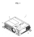
- FIG. 1 is a schematic perspective view of the image projection apparatus 1 according to an example embodiment.
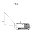
- FIG. 2 is a schematic side view of the image projection apparatus 1 of FIG. 1 showing a light projection to a screen used as a projection face.
- the image projection apparatus 1 is, for example, a projector, which generates images based on image data input from an information processing apparatus such as a personal computer (PC) and an image capturing apparatus such as a video camera, and projects the images onto the screen 15.
- an information processing apparatus such as a personal computer (PC)
- an image capturing apparatus such as a video camera
- the image projection apparatus 1 includes a lamp as a light source and many electronic circuits therein, and temperature inside the image projection apparatus 1 increases when the image projection apparatus 1 is activated. Therefore, the image projection apparatus 1 includes an air-intake port 11 and an air-discharge port 12 so that the inside temperature does not exceed heat-resistance temperature of internal components, in which an air-cooling system using forced air draft is typically employed.
- FIG. 3A is a schematic perspective view of the image projection apparatus 1 when an outer cover 2 is removed.
- FIG. 3B is an expanded view of an optical engine 3 and a light source unit 4 indicated by a circular line in FIG. 3A .
- the image projection apparatus 1 includes, for example, the optical engine 3 and the light source unit 4.
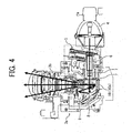
- FIG. 4 is a schematic cross-sectional view of the optical engine 3 and the light source unit 4.
- the optical engine 3 includes a radiation unit 3 a used as an optical radiation system and the projection unit 3b used as an optical projection system.
- an air-intake fan 13 is disposed inside the air-intake port 11, and an air-discharge fan 14 is disposed inside the air-discharge port 12.
- the inside of the image projection apparatus 1 can be cooled by forced air draft which can be generated by in-taking air from the air-intake fan 13 and discharging the air from the air-discharge fan 14.
- the image projection apparatus 1 As to the image projection apparatus 1, light (i.e., white light) from the light source unit 4 used as the light source is radiated to the radiation unit 3 a of the optical engine 3. In the radiation unit 3a, the radiated white light is separated into red, green and blue (RGB) light, and then guided to the image generation element unit 10 by using the optical radiation system.
- the image generation element unit10 generates an image based on modulated signals, and then the optical projection system such as the projection unit 3b enlarges and projects the image onto the screen 15.
- the light source of the light source unit 4 is, for example, a high pressure mercury lamp.
- the radiation unit 3a of the optical engine 3 includes, for example, the color wheel 5, the light tunnel 6, and the relay lens 7, the flat-face mirror 8 and the concave-face mirror 9.
- the color wheel 5 separates light emitted from the light source.
- the light tunnel 6 guides light exiting from the color wheel 5 to the optical radiation system, wherein the relay lens 7, the flat-face mirror 8 and the concave-face mirror 9 can be collectively used as the optical radiation system.
- the radiation unit 3 a includes the image generation element unit 10.
- the white light from the light source is sequentially converted into RGB light for each unit time by the color wheel 5 having a disk shape, and the light exits from the color wheel 5. Then, the light exiting from the color wheel 5 is guided to the light tunnel 6 having a cylindrical shape composed of glass plates.
- the image generation element unit 10 includes a digital micro-mirror device (DMD) element 10a used as an image generation element.
- the DMD element 10a includes a plurality of micro mirrors having shaped the mirror face as rectangular shape. Each of the micro mirrors is time-divisionally driven based on image data, with which the micro mirrors reflect light to generate projection light used for forming a given image.
- the DMD element 10a having the plurality of micro mirrors reflects light used for projection (i.e., projection light) to a projection lens, and reflects light not used for projection to an OFF plate.
- the projection light reflects from the image generation element unit 10 to the projection unit 3b, and the projection light passing through a plurality of projection lenses in the projection unit 3b is enlarged and projected onto the screen 15.
- each of the relay lens 7, the flat-face mirror 8, the concave-face mirror 9, the image generation element unit 10, and the projection unit 3b can be covered with a housing at the light incident side, and mating faces of the housings are sealed by a seal member.
- the color wheel 5 is a rotator that rotates at a high rotation speed such as 7,000 rpm to 12,000 rpm (rotation per minute) by using a driver such as a motor. Because the driver of the color wheel 5 generates heat, the driver is required to be cooled under a given temperature so that the driver can be used under a safe condition. Due to such requirement, the color wheel 5 is difficult to seal.
- the light tunnel 6 which is typically a hollow tube structure, is disposed near the color wheel 5. Further, because a holding member of the light tunnel 6 becomes high temperature due to light reflected inside the light tunnel 6, the light tunnel 6 is required to be cooled. Due to such requirement, the light tunnel 6 is also difficult to seal.
- the color wheel 5 and the light tunnel 6 are required to be disposed in an open space, and required to be cooled using air supplied by forced air draft.
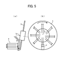
- FIG. 5(a) is a schematic side view of the color wheel 5 and the light tunnel 6.
- FIG. 5(b) is a schematic view of the color wheel 5 and the light tunnel 6 viewed from a side of the light tunnel 6, in which the light tunnel 6 is indicated by a dotted line.
- the color wheel 5 is spaced apart from the light tunnel 6 with a given clearance set along the light radiation direction from the light source.
- the clearance is several millimeters such as 2 mm to 3 mm.
- the rotation axis of the color wheel 5 is disposed with a given angle (i.e., slanted) with respect to an optical axis of light extending from the light source to the light tunnel 6.
- the color wheel 5 i.e., rotator
- a direct current (DC) motor Because the airflow speed near the rotator is fast, a negative pressure occurs easily, with which an airflow occurs from the center of the rotator (i.e., rotation center 5a) toward the outer periphery of the rotator (i.e., rotation center 5a).
- airflow that has entered from the rotation center 5a of the color wheel 5 flows along a face of the color wheel 5 as indicated by an arrow "A" (hereinafter, airflow "A") illustrated in FIG. 5(b) when the color wheel 5 rotates in a given direction, in which airflow "A" flowing from the rotation center 5a to the outer periphery of the color wheel 5 occurs with a radial pattern.
- the light tunnel 6 is disposed at one portion facing the peripheral of the color wheel 5. Therefore, the airflow "A” is taken into the inside of the light tunnel 6 as illustrated in FIG. 5 (a) , with which dust included in the airflow "A” may adhere inside the light tunnel 6.
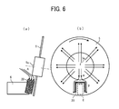
- the image projection apparatus 1 includes the shield 20 at a space between the color wheel 5 and the light tunnel 6 along the light radiation direction from the light source unit 4.
- the shield 20 shields at least at one portion of the light tunnel 6 facing the rotation center 5a of the color wheel 5.
- FIG. 6(a) is a schematic side view of the color wheel 5 and the light tunnel 6 disposed with the shield 20 between the color wheel 5 and the light tunnel 6.
- FIG. 6(b) is a schematic view of the color wheel 5, the light tunnel 6 and the shield 20 viewed from the light tunnel 6.
- the shield 20 is disposed at a space between the color wheel 5 and the light tunnel 6 along light radiation direction from the light source unit 4 so that the airflow "A" flowing from the rotation center 5a to the outer periphery of the color wheel 5 can be blocked.
- the shield 20 is disposed to cover a top face and both side faces of the light tunnel 6, in which the top face of the light tunnel 6 is a face facing the rotation center 5a of the color wheel 5.
- the shield 20 disposed at the space between the color wheel 5 and the light tunnel 6 covers a given portion of the light tunnel 6 from the top face and both side faces of the light tunnel 6.
- the shield 20 is disposed with a given angle similar to the color wheel 5 to cover the light tunnel 6, but not limited hereto. Further, the shield 20 is required to be disposed without interrupting a light path in the light tunnel 6 shown by a dotted line in FIG. 6(b) .
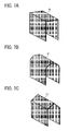
- FIG. 7A is a schematic perspective view of one example of the shield 20 illustrated in FIG. 6 .
- the shield 20 of FIG. 7A has a U-shaped configuration having three faces square to the adjacent face to cover the top face and both side faces of the light tunnel 6.
- the shape of the shield 20 is not limited hereto.
- the shield 20 can employ a U-shaped configuration having R at the top face as illustrated in FIG. 7B
- the shield 20 can employ a U-shaped configuration having a sharp-angled shape for the top face as illustrated in FIG. 7C .
- the shield 20 is preferably made of materials having higher thermal conductivity such as aluminum, aluminum allow, cupper or the like.
- the thickness of the shield 20 can be 0.3 mm or so, but not limited hereto.
- the shield 20 can be fixed to the above described position with any fixing methods.
- the shield 20 can be attached to a member fixing the light tunnel 6, and the shield 20 can be attached to an aperture member disposed near the color wheel 5 and the light tunnel 6.
- the shield 20 can be integrally formed with an aperture member disposed near the color wheel 5 and the light tunnel 6.
- the shield 20 can be fixed to an outer periphery of the light tunnel 6.
- the shield 20 is disposed at a portion corresponding to the top face and both side faces of the light tunnel 6 to cover a given portion of space between the light tunnel 6 and the color wheel 5.
- the shield 20 is preferably disposed at a portion to suppress an intrusion of airflow "A" into the light tunnel 6.
- the shield 20 is disposed at the space between the light tunnel 6 and the color wheel 5 that can block the airflow from the rotation center 5a of the color wheel 5 at least at one portion.
- the shield 20 is disposed to cover the space corresponding to a given portion extending from the top face (i.e., face facing the rotation center 5a) of the light tunnel 6.
- the shield 20 is preferably disposed to cover the space corresponding to the given portion extending from the top face and both side faces of the light tunnel 6. By covering the both side faces of the light tunnel 6, an airflow that has changed its flow due to the top face may not enter inside the light tunnel 6 by taking a flow pattern of rounding about the shield 20.
- a clearance of several millimeters is set between the light tunnel 6 and the color wheel 5.
- the clearance L between the shield 20 and the color wheel 5 after disposing the shield 20 is preferably set 1.0 mm or less. With this configuration, dust intrusion into the light tunnel 6 can be effectively suppressed.
- an airflow around the color wheel can be changed to another airflow by disposing the shield so that the light tunnel is not intruded by the airflow, with which dust intrusion into the light tunnel can be effectively suppressed, and decrease of light transmittance can be effectively suppressed, with which decrease of luminance of projection light or projection image can be effectively suppressed,
- an air filter is not disposed for the image projection apparatus 1 to prevent dust intrusion, with which cleaning and replacement of the air filter can be omitted, and rotation speed of the air-intake fan can be decreased, with which noise reduction can be achieved.
Landscapes
- Physics & Mathematics (AREA)
- General Physics & Mathematics (AREA)
- Optics & Photonics (AREA)
- Projection Apparatus (AREA)
- Transforming Electric Information Into Light Information (AREA)
- Video Image Reproduction Devices For Color Tv Systems (AREA)
Abstract
Description
- The present invention relates to an image projection apparatus.
- Image projection apparatuses known as projectors have been widely used with the advancement of higher resolution of liquid crystal panels, enhancement of brightness of light source lamps due to higher efficiency, and lower price. Further, light-weight and compact image projection apparatuses using digital micro-mirror devices (DMD) as an image generation element have been widely used in offices, schools, and homes. For example, front type projectors having enhanced portability have been used for small meetings of several persons.
- Further, projectors are demanded to project a larger image while also demanded to be compact for a projection space required outside the projectors. Recently, short focus projectors having a projection distance of 1 m to 2 m and a projection size of 60 inches to 80 inches have been developed. When projectors having a longer projection distance are placed on a table in a meeting room, the projectors need to be placed at position on the table far from a screen. By contrast, the short focus projectors can be placed near the screen on a table, with which a rear space of projectors on the table can be used freely.
- The image projection apparatus includes a light source such as a lamp. Temperature in the image projection apparatus increases when the light source is ON. Therefore, the image projection apparatus includes a cooling unit such as an air-intake port and an air-discharge port to prevent temperature increase, and fans such as an air-intake fan and an air-discharge fan are disposed near each of the air-intake port and air-discharge port to generate forced air draft.
- Further, the image projection apparatus having the air-intake port and air-discharge port includes an optical radiation system and an optical projection system, wherein the optical radiation system radiates light emitted from the light source to an image generation element, and the optical projection system projects an image generated by the image generation element to a projection face. As to this image projection apparatus, dust in air may intrude inside the image projection apparatus through the air-intake port and air-discharge port, and then may stay in a light path in the optical radiation system and the optical projection system, with which images having error such as poor quality images may be projected.
- In view of this dust intrusion into the apparatus, an air filter can be provided before the air-intake fan to reduce an amount of dust intrusion, and optical parts can be sealed so that dust does not intrude in the optical radiation system and the optical projection system.
- However, when the air filter is disposed before the air-intake fan, an air-intake area decreases, with which wind amount decreases and cooling performance in the apparatus decreases. In this case, rotation speed of the fan can be increased to maintain the cooling performance, but the increased rotation speed increases noise. Further, when dust adheres on the air filter, the cooling performance decreases, in which the apparatus is stopped and a user needs to clean and replace the air filter periodically, which is not convenient.
- When the optical parts are sealed to prevent dust intrusion in the optical radiation system and the optical projection system, dust does not adhere on a light path in the optical radiation system and the optical projection system, and a normal projection image can be generated. However, some parts cannot be sealed. For example, a color wheel and a light tunnel disposed between the light source and the optical radiation system cannot be sealed because they are required to be cooled by air. Therefore, if dust adheres inside the light tunnel, luminance of projection image decreases.
-
JP-2004-212726-A - As above described, the color wheel and the light tunnel cannot be sealed because they are required to be cooled by air. The color wheel can be rotated about the rotation center using a driver such as a motor. Because airflow speed near the color wheel (i.e., rotator) is fast, negative pressure occurs, with which airflow directed from the center to the periphery of the rotator occurs. Because dust flows along with the airflow, dust may adhere inside the light tunnel disposed at a portion of periphery of the color wheel. If dust adheres inside the light tunnel, light transmittance decreases and luminance of projection image decreases.
- The above mentioned
JP-2004-212726-A - In one aspect of the present invention, an image projection apparatus is devised. The image projection apparatus includes a light source that emits light; an image generation element to generate an image; an optical radiation system to irradiate the image generation element using the light emitted from the light source; an optical projection system to project the image generated by the image generation element onto a projection face; a color wheel, disposed on a light path of light emitted from the light source, to separate the light while being rotated; a light tunnel to guide light exiting from the color wheel to the optical radiation system; and a shield disposed in a space between the color wheel and the light tunnel in a light radiation direction from which the light from the light source is irradiated. The shield covers at least a part of a side of the light tunnel facing a rotation center of the color wheel. As to the above described image projection apparatus, dust intrusion to the light tunnel can be suppressed and luminance decrease of projection image can be suppressed.
- A more complete appreciation of the disclosure and many of the attendant advantages and features thereof can be readily obtained and understood from the following detailed description with reference to the accompanying drawings, wherein:
-
FIG. 1 is a schematic perspective view of an image projection apparatus according to an example embodiment; -
FIG. 2 is a schematic side view of the image projection apparatus ofFIG. 1 and a light projection to a screen used as a projection face; -
FIG. 3A is a schematic perspective view of the image projection apparatus ofFIG. 1 when an outer cover is removed; -
FIG. 3B is an expanded view of a portion indicated by a circular line inFIG. 3A -
FIG. 4 is a schematic cross-sectional view of an optical irradiation unit, an optical projection unit, and a light source unit; -
FIG. 5(a) is a schematic side view of a color wheel and a light tunnel; -
FIG. 5(b) is a schematic view the color wheel and the light tunnel viewed from the light tunnel; -
FIG. 6(a) is a schematic side view of the color wheel and the light tunnel having disposed with a shield between the color wheel and the light tunnel; -
FIG. 6(b) is a schematic view of the color wheel, the light tunnel and the shield viewed from the light tunnel. -
FIGs. 7A, 7B, and 7C are schematic perspective views of examples of shield; and -
FIG. 8 is a schematic side view of the shield and the color wheel having a clearance between the shield and the color; - The accompanying drawings are intended to depict exemplary embodiments of the present invention and should not be interpreted to limit the scope thereof. The accompanying drawings are not to be considered as drawn to scale unless explicitly noted, and identical or similar reference numerals designate identical or similar components throughout the several views.
- A description is now given of exemplary embodiments of the present invention. It should be noted that although such terms as first, second, etc. may be used herein to describe various elements, components, regions, layers and/or sections, it should be understood that such elements, components, regions, layers and/or sections are not limited thereby because such terms are relative, that is, used only to distinguish one element, component, region, layer or section from another region, layer or section. Thus, for example, a first element, component, region, layer or section discussed below could be termed a second element, component, region, layer or section without departing from the teachings of the present invention.
- In addition, it should be noted that the terminology used herein is for the purpose of describing particular embodiments only and is not intended to be limiting of the present invention. Thus, for example, as used herein, the singular forms "a", "an" and "the" are intended to include the plural forms as well, unless the context clearly indicates otherwise. Moreover, the terms "includes" and/or "including", when used in this specification, specify the presence of stated features, integers, steps, operations, elements, and/or components, but do not preclude the presence or addition of one or more other features, integers, steps, operations, elements, components, and/or groups thereof.
- Furthermore, although in describing views illustrated in the drawings, specific terminology is employed for the sake of clarity, the present disclosure is not limited to the specific terminology so selected and it is to be understood that each specific element includes all technical equivalents that operate in a similar manner and achieve a similar result. Referring now to the drawings, an apparatus or system according to an example embodiment is described hereinafter.
- An
image projection apparatus 1 according to an example embodiment includes, for example, a light source such as alight source unit 4, an image generation element (imagegeneration element unit 10,DMD element 10a), an optical radiation unit or system (relay lens 7, flat-face mirror 8, concave-face mirror 9), an optical projection unit or system, acolor wheel 5, alight tunnel 6, and ashield 20. - The light source such as the
light source unit 4 emits light. The image generation element, including such as an imagegeneration element unit 10 and a digital mirror device (DMD)element 10a, generates an image. The optical radiation unit or system, including such as a relay lens 7, a flat-face mirror 8, a concave-face mirror 9, radiates the image generation element using light from the light source. The optical projection unit or system projects the image generated by the image generation element onto a projection face such as a screen 15 (FIG. 2 ). - The
color wheel 5 is disposed on a light path of light emitted from the light source, and separates light when rotating about the axis of thecolor wheel 5. Thelight tunnel 6 guides light exiting from thecolor wheel 5 to the optical radiation unit or system. Theshield 20 is disposed in a space between thecolor wheel 5 and thelight tunnel 6 along a light radiation direction from the light source, and theshield 20 shields or covers at least a portion of thelight tunnel 6 facing the center of thecolor wheel 5. -
FIG. 1 is a schematic perspective view of theimage projection apparatus 1 according to an example embodiment.FIG. 2 is a schematic side view of theimage projection apparatus 1 ofFIG. 1 showing a light projection to a screen used as a projection face. - The
image projection apparatus 1 is, for example, a projector, which generates images based on image data input from an information processing apparatus such as a personal computer (PC) and an image capturing apparatus such as a video camera, and projects the images onto thescreen 15. - The
image projection apparatus 1 includes a lamp as a light source and many electronic circuits therein, and temperature inside theimage projection apparatus 1 increases when theimage projection apparatus 1 is activated. Therefore, theimage projection apparatus 1 includes an air-intake port 11 and an air-discharge port 12 so that the inside temperature does not exceed heat-resistance temperature of internal components, in which an air-cooling system using forced air draft is typically employed. -
FIG. 3A is a schematic perspective view of theimage projection apparatus 1 when anouter cover 2 is removed.FIG. 3B is an expanded view of anoptical engine 3 and alight source unit 4 indicated by a circular line inFIG. 3A . As illustrated inFIGs. 3A and 3B , theimage projection apparatus 1 includes, for example, theoptical engine 3 and thelight source unit 4.FIG. 4 is a schematic cross-sectional view of theoptical engine 3 and thelight source unit 4. Theoptical engine 3 includes aradiation unit 3 a used as an optical radiation system and theprojection unit 3b used as an optical projection system. - As illustrated in
FIG. 3 , an air-intake fan 13 is disposed inside the air-intake port 11, and an air-discharge fan 14 is disposed inside the air-discharge port 12. The inside of theimage projection apparatus 1 can be cooled by forced air draft which can be generated by in-taking air from the air-intake fan 13 and discharging the air from the air-discharge fan 14. - As to the
image projection apparatus 1, light (i.e., white light) from thelight source unit 4 used as the light source is radiated to theradiation unit 3 a of theoptical engine 3. In theradiation unit 3a, the radiated white light is separated into red, green and blue (RGB) light, and then guided to the imagegeneration element unit 10 by using the optical radiation system. The image generation element unit10 generates an image based on modulated signals, and then the optical projection system such as theprojection unit 3b enlarges and projects the image onto thescreen 15. - The light source of the
light source unit 4 is, for example, a high pressure mercury lamp. Further, theradiation unit 3a of theoptical engine 3 includes, for example, thecolor wheel 5, thelight tunnel 6, and the relay lens 7, the flat-face mirror 8 and the concave-face mirror 9. Thecolor wheel 5 separates light emitted from the light source. Thelight tunnel 6 guides light exiting from thecolor wheel 5 to the optical radiation system, wherein the relay lens 7, the flat-face mirror 8 and the concave-face mirror 9 can be collectively used as the optical radiation system. Further, theradiation unit 3 a includes the imagegeneration element unit 10. - In the
radiation unit 3a, the white light from the light source is sequentially converted into RGB light for each unit time by thecolor wheel 5 having a disk shape, and the light exits from thecolor wheel 5. Then, the light exiting from thecolor wheel 5 is guided to thelight tunnel 6 having a cylindrical shape composed of glass plates. - Then, the light exiting from the
light tunnel 6 is condensed by the relay lens 7 composed of two lenses while correcting chromatic aberration on the optical axis. Further, the light exiting from the relay lens 7 is reflected by the flat-face mirror 8 and the concave-face mirror 9, and is radiated to the imagegeneration element unit 10. The imagegeneration element unit 10 includes a digital micro-mirror device (DMD)element 10a used as an image generation element. TheDMD element 10a includes a plurality of micro mirrors having shaped the mirror face as rectangular shape. Each of the micro mirrors is time-divisionally driven based on image data, with which the micro mirrors reflect light to generate projection light used for forming a given image. - Based on the time-divisional image data, the
DMD element 10a having the plurality of micro mirrors reflects light used for projection (i.e., projection light) to a projection lens, and reflects light not used for projection to an OFF plate. The projection light reflects from the imagegeneration element unit 10 to theprojection unit 3b, and the projection light passing through a plurality of projection lenses in theprojection unit 3b is enlarged and projected onto thescreen 15. - In the
radiation unit 3a, each of the relay lens 7, the flat-face mirror 8, the concave-face mirror 9, the imagegeneration element unit 10, and theprojection unit 3b can be covered with a housing at the light incident side, and mating faces of the housings are sealed by a seal member. - The
color wheel 5 is a rotator that rotates at a high rotation speed such as 7,000 rpm to 12,000 rpm (rotation per minute) by using a driver such as a motor. Because the driver of thecolor wheel 5 generates heat, the driver is required to be cooled under a given temperature so that the driver can be used under a safe condition. Due to such requirement, thecolor wheel 5 is difficult to seal. - Further, the
light tunnel 6, which is typically a hollow tube structure, is disposed near thecolor wheel 5. Further, because a holding member of thelight tunnel 6 becomes high temperature due to light reflected inside thelight tunnel 6, thelight tunnel 6 is required to be cooled. Due to such requirement, thelight tunnel 6 is also difficult to seal. - As described above, the
color wheel 5 and thelight tunnel 6 are required to be disposed in an open space, and required to be cooled using air supplied by forced air draft. - A description is given of airflow generated for cooling the
color wheel 5 and thelight tunnel 6 using air.FIG. 5(a) is a schematic side view of thecolor wheel 5 and thelight tunnel 6.FIG. 5(b) is a schematic view of thecolor wheel 5 and thelight tunnel 6 viewed from a side of thelight tunnel 6, in which thelight tunnel 6 is indicated by a dotted line. In consideration of vibrations during rotation, thecolor wheel 5 is spaced apart from thelight tunnel 6 with a given clearance set along the light radiation direction from the light source. For example, the clearance is several millimeters such as 2 mm to 3 mm. Further, as illustrated inFIG.5 , the rotation axis of thecolor wheel 5 is disposed with a given angle (i.e., slanted) with respect to an optical axis of light extending from the light source to thelight tunnel 6. - As described above, the color wheel 5 (i.e., rotator) is rotated in a direction shown by an arrow in
FIG. 5(b) with high speed by using a direct current (DC) motor. Because the airflow speed near the rotator is fast, a negative pressure occurs easily, with which an airflow occurs from the center of the rotator (i.e.,rotation center 5a) toward the outer periphery of the rotator (i.e.,rotation center 5a). - Further, when dust in external air is taken in the
image projection apparatus 1 through the air-intake port 11 and the air-intake fan 13 of theimage projection apparatus 1, an airflow contaminated by dust may be intaken to therotation center 5a of thecolor wheel 5. - The airflow that has entered from the
rotation center 5a of thecolor wheel 5 flows along a face of thecolor wheel 5 as indicated by an arrow "A" (hereinafter, airflow "A") illustrated inFIG. 5(b) when thecolor wheel 5 rotates in a given direction, in which airflow "A" flowing from therotation center 5a to the outer periphery of thecolor wheel 5 occurs with a radial pattern. - As illustrated in
FIG. 5 , thelight tunnel 6 is disposed at one portion facing the peripheral of thecolor wheel 5. Therefore, the airflow "A" is taken into the inside of thelight tunnel 6 as illustrated inFIG. 5 (a) , with which dust included in the airflow "A" may adhere inside thelight tunnel 6. - If dust adheres inside the
light tunnel 6, light transmittance of glass of thelight tunnel 6 decreases due to adhered dust, with which luminance of projection light or projection image may decrease. - In view of the dust issue, the
image projection apparatus 1 according to an example embodiment includes theshield 20 at a space between thecolor wheel 5 and thelight tunnel 6 along the light radiation direction from thelight source unit 4. Theshield 20 shields at least at one portion of thelight tunnel 6 facing therotation center 5a of thecolor wheel 5. With this configuration, an airflow pattern occurring around thecolor wheel 5 can be changed so that airflow intrusion to thelight tunnel 6 can be blocked, with which adhesion of dust included in airflow to the inside of thelight tunnel 6 can be suppressed, in particular prevented. -
FIG. 6(a) is a schematic side view of thecolor wheel 5 and thelight tunnel 6 disposed with theshield 20 between thecolor wheel 5 and thelight tunnel 6.FIG. 6(b) is a schematic view of thecolor wheel 5, thelight tunnel 6 and theshield 20 viewed from thelight tunnel 6. - As illustrated in
FIG. 6 , theshield 20 is disposed at a space between thecolor wheel 5 and thelight tunnel 6 along light radiation direction from thelight source unit 4 so that the airflow "A" flowing from therotation center 5a to the outer periphery of thecolor wheel 5 can be blocked. For example, theshield 20 is disposed to cover a top face and both side faces of thelight tunnel 6, in which the top face of thelight tunnel 6 is a face facing therotation center 5a of thecolor wheel 5. As above described, theshield 20 disposed at the space between thecolor wheel 5 and thelight tunnel 6 covers a given portion of thelight tunnel 6 from the top face and both side faces of thelight tunnel 6. - When the
shield 20 is not disposed, a portion of airflow "A" enters thelight tunnel 6 as illustrated inFIG. 5 . When theshield 20 is disposed, as illustrated inFIG.6(b) , the airflow "A" changes a flow pattern indicated by an arrow "B" that flows along an outer contour of theshield 20, with which intrusion of dust included in air into thelight tunnel 6 can be suppressed, in particular prevented. - In a configuration of
FIG. 6 , theshield 20 is disposed with a given angle similar to thecolor wheel 5 to cover thelight tunnel 6, but not limited hereto. Further, theshield 20 is required to be disposed without interrupting a light path in thelight tunnel 6 shown by a dotted line inFIG. 6(b) . -
FIG. 7A is a schematic perspective view of one example of theshield 20 illustrated inFIG. 6 . Theshield 20 ofFIG. 7A has a U-shaped configuration having three faces square to the adjacent face to cover the top face and both side faces of thelight tunnel 6. The shape of theshield 20 is not limited hereto. For example, theshield 20 can employ a U-shaped configuration having R at the top face as illustrated inFIG. 7B , and theshield 20 can employ a U-shaped configuration having a sharp-angled shape for the top face as illustrated inFIG. 7C . - Further, as described above because the
color wheel 5 and thelight tunnel 6 become high temperature, components near thecolor wheel 5 and thelight tunnel 6 are required to be made of material having higher heat dissipation. Specifically, theshield 20 is preferably made of materials having higher thermal conductivity such as aluminum, aluminum allow, cupper or the like. For example, by using aluminum having higher heat dissipation, temperature increase of thelight tunnel 6 can be suppressed, and heat deformation of glass in thelight tunnel 6 can be suppressed. Further, the thickness of theshield 20 can be 0.3 mm or so, but not limited hereto. - Further, the
shield 20 can be fixed to the above described position with any fixing methods. For example, theshield 20 can be attached to a member fixing thelight tunnel 6, and theshield 20 can be attached to an aperture member disposed near thecolor wheel 5 and thelight tunnel 6. Further, theshield 20 can be integrally formed with an aperture member disposed near thecolor wheel 5 and thelight tunnel 6. Further, theshield 20 can be fixed to an outer periphery of thelight tunnel 6. - In a configuration of
FIG. 6 , theshield 20 is disposed at a portion corresponding to the top face and both side faces of thelight tunnel 6 to cover a given portion of space between thelight tunnel 6 and thecolor wheel 5. Theshield 20 is preferably disposed at a portion to suppress an intrusion of airflow "A" into thelight tunnel 6. Theshield 20 is disposed at the space between thelight tunnel 6 and thecolor wheel 5 that can block the airflow from therotation center 5a of thecolor wheel 5 at least at one portion. Preferably, theshield 20 is disposed to cover the space corresponding to a given portion extending from the top face (i.e., face facing therotation center 5a) of thelight tunnel 6. - Further, as described above, the
shield 20 is preferably disposed to cover the space corresponding to the given portion extending from the top face and both side faces of thelight tunnel 6. By covering the both side faces of thelight tunnel 6, an airflow that has changed its flow due to the top face may not enter inside thelight tunnel 6 by taking a flow pattern of rounding about theshield 20. - A description is given of a clearance L between the
shield 20 and thecolor wheel 5 with reference toFIG. 8 . Even if theshield 20 is disposed, when the clearance L between theshield 20 and thecolor wheel 5 is large, an airflow may enter the clearance L and then inside thelight tunnel 6 due to a positional relationship with respect to thecolor wheel 5. - As described above, for example, a clearance of several millimeters is set between the
light tunnel 6 and thecolor wheel 5. The clearance L between theshield 20 and thecolor wheel 5 after disposing theshield 20 is preferably set 1.0 mm or less. With this configuration, dust intrusion into thelight tunnel 6 can be effectively suppressed. - In the above described
image projection apparatus 1 having a configuration that dust in external air may intrude inside theimage projection apparatus 1 through an air-intake port or the like, an airflow around the color wheel can be changed to another airflow by disposing the shield so that the light tunnel is not intruded by the airflow, with which dust intrusion into the light tunnel can be effectively suppressed, and decrease of light transmittance can be effectively suppressed, with which decrease of luminance of projection light or projection image can be effectively suppressed, - Further, an air filter is not disposed for the
image projection apparatus 1 to prevent dust intrusion, with which cleaning and replacement of the air filter can be omitted, and rotation speed of the air-intake fan can be decreased, with which noise reduction can be achieved. - As to the above described image projection apparatus, dust intrusion to the light tunnel can be suppressed and luminance decrease of projection image can be suppressed.
- Numerous additional modifications and variations are possible in light of the above teachings. It is therefore to be understood that within the scope of the appended claims, the disclosure of the present invention may be practiced otherwise than as specifically described herein. For example, elements and/or features of different examples and illustrative embodiments may be combined each other and/or substituted for each other within the scope of this disclosure and appended claims.
Claims (5)
- An image projection apparatus (1) comprising:a light source (4) that emits light;an image generation element (10) to generate an image;an optical radiation system (7, 8, 9) to irradiate the image generation element using the light emitted from the light source (4);an optical projection system (3b) to project the image generated by the image generation element onto a projection face;a color wheel (5), disposed on a light path of light emitted from the light source (4), to separate the light while being rotated;a light tunnel (6) to guide light exiting from the color wheel (5) to the optical radiation system (7, 8, 9); anda shield (20) disposed in a space between the color wheel (5) and the light tunnel (6) in a light radiation direction from which the light from the light source(4) is irradiated, the shield (20) covering at least a part of a side of the light tunnel (6) facing a rotation center of the color wheel (5).
- The image projection apparatus (1) of claim 1, wherein the shield (20) covers an area extending at least a part of a top face of the light tunnel (6) in the space, and the top face faces the rotation center of the color wheel (5).
- The image projection apparatus (1) of claim 1, wherein the shield (20) covers an area extending at least a part of a top face and a part of both side faces of the light tunnel (6) in the space.
- The image projection apparatus (1) of any one of claims 1 to 3, wherein the shield (20) has a clearance of 1 mm or less with the color wheel (5).
- The image projection apparatus (1) of any one of claims 1 to 4, wherein the shield (20) is made of aluminum.
Applications Claiming Priority (1)
| Application Number | Priority Date | Filing Date | Title |
|---|---|---|---|
| JP2013121822A JP6232761B2 (en) | 2013-06-10 | 2013-06-10 | Image projection device |
Publications (2)
| Publication Number | Publication Date |
|---|---|
| EP2816405A2 true EP2816405A2 (en) | 2014-12-24 |
| EP2816405A3 EP2816405A3 (en) | 2015-08-19 |
Family
ID=50721712
Family Applications (1)
| Application Number | Title | Priority Date | Filing Date |
|---|---|---|---|
| EP14168723.6A Withdrawn EP2816405A3 (en) | 2013-06-10 | 2014-05-16 | Image projection apparatus with dust protection |
Country Status (4)
| Country | Link |
|---|---|
| US (1) | US9395607B2 (en) |
| EP (1) | EP2816405A3 (en) |
| JP (1) | JP6232761B2 (en) |
| CN (1) | CN104238244B (en) |
Families Citing this family (3)
| Publication number | Priority date | Publication date | Assignee | Title |
|---|---|---|---|---|
| JP6613664B2 (en) * | 2015-07-10 | 2019-12-04 | セイコーエプソン株式会社 | Wavelength conversion device, illumination device, and projector |
| TWI594061B (en) * | 2015-07-21 | 2017-08-01 | 中強光電股份有限公司 | Wheel assembly and projection device using the same |
| CN109031864A (en) * | 2018-07-10 | 2018-12-18 | 苏州佳世达光电有限公司 | Projector and its ray machine |
Citations (1)
| Publication number | Priority date | Publication date | Assignee | Title |
|---|---|---|---|---|
| JP2004212726A (en) | 2003-01-06 | 2004-07-29 | Plus Vision Corp | Optical transmission member with heat sink and projector using the same |
Family Cites Families (15)
| Publication number | Priority date | Publication date | Assignee | Title |
|---|---|---|---|---|
| US7046897B2 (en) * | 2002-06-13 | 2006-05-16 | Unaxis Balzers Ltd. | Light beam preparation arrangement |
| US6883937B2 (en) * | 2002-08-23 | 2005-04-26 | Jds Uniphase Corporation | Sequential color recapture light system |
| JP2004212816A (en) * | 2003-01-07 | 2004-07-29 | Fuji Photo Optical Co Ltd | Rod integrator holder and projection image display device provided therewith |
| JP2004239934A (en) | 2003-02-03 | 2004-08-26 | Plus Vision Corp | Illumination optical system and projector using the same |
| US7178948B2 (en) | 2004-08-17 | 2007-02-20 | Hewlett-Packard Development Company, L.P. | Light collection system |
| US7566135B2 (en) | 2005-01-13 | 2009-07-28 | Lg Electronics Inc. | Light tunnel of DLP projection system |
| KR100693530B1 (en) | 2005-01-13 | 2007-03-14 | 엘지전자 주식회사 | Light Tunnel Structure of DLP Projection Television |
| CN100422849C (en) | 2005-02-23 | 2008-10-01 | 扬明光学股份有限公司 | Projector with a light source |
| JP2007147965A (en) | 2005-11-28 | 2007-06-14 | Plus Vision Corp | projector |
| TWI276910B (en) * | 2005-12-27 | 2007-03-21 | Young Optics Inc | Illumination system |
| JP2007256337A (en) | 2006-03-20 | 2007-10-04 | Funai Electric Co Ltd | Projector |
| JP2008292887A (en) * | 2007-05-28 | 2008-12-04 | Funai Electric Co Ltd | Image projection device |
| JP5197409B2 (en) * | 2009-01-29 | 2013-05-15 | 三菱電機株式会社 | Projection display |
| TWI401525B (en) * | 2009-08-11 | 2013-07-11 | Qisda Corp | Light pipe and projecting apparatus utilizing the light pipe |
| JP5510828B2 (en) | 2010-09-16 | 2014-06-04 | 株式会社リコー | LIGHT SOURCE DEVICE, AND LIGHTING DEVICE AND PROJECTION DISPLAY DEVICE HAVING THE LIGHT SOURCE DEVICE |
-
2013
- 2013-06-10 JP JP2013121822A patent/JP6232761B2/en not_active Expired - Fee Related
-
2014
- 2014-05-16 EP EP14168723.6A patent/EP2816405A3/en not_active Withdrawn
- 2014-05-28 US US14/289,028 patent/US9395607B2/en not_active Expired - Fee Related
- 2014-06-05 CN CN201410252880.1A patent/CN104238244B/en not_active Expired - Fee Related
Patent Citations (1)
| Publication number | Priority date | Publication date | Assignee | Title |
|---|---|---|---|---|
| JP2004212726A (en) | 2003-01-06 | 2004-07-29 | Plus Vision Corp | Optical transmission member with heat sink and projector using the same |
Also Published As
| Publication number | Publication date |
|---|---|
| CN104238244B (en) | 2016-05-18 |
| JP2014238540A (en) | 2014-12-18 |
| EP2816405A3 (en) | 2015-08-19 |
| US9395607B2 (en) | 2016-07-19 |
| US20140362352A1 (en) | 2014-12-11 |
| JP6232761B2 (en) | 2017-11-22 |
| CN104238244A (en) | 2014-12-24 |
Similar Documents
| Publication | Publication Date | Title |
|---|---|---|
| CN2632723Y (en) | Rear-projection projector | |
| JP5127474B2 (en) | Image projection device | |
| TWI330754B (en) | ||
| WO2004003391A1 (en) | Axial flow fan and projector using the same | |
| KR100727517B1 (en) | Projection display device, image projection system and light source device | |
| JP6645667B2 (en) | Projection display device | |
| JP6376414B2 (en) | Fluorescent light emitting device, light source device and image projection device | |
| JP2006189650A (en) | Projection display device and cooling structure | |
| JP2004354853A (en) | Cooling device, optical device and projector provided with the cooling device | |
| JP6277608B2 (en) | Cooling structure, image projection device, electronic equipment | |
| US9395607B2 (en) | Image projection apparatus including a shield | |
| US9645478B2 (en) | Cooling device, image projection apparatus, and electronic apparatus | |
| JP2015005715A (en) | Cooling device, cooling structure, image projector, and electronic apparatus | |
| JP2004045990A (en) | Display device | |
| JP2017223844A (en) | Image projection device | |
| JP2018146885A (en) | Illumination device and image projection device | |
| JP4175327B2 (en) | Projector device | |
| JP2018036447A (en) | Display device and display apparatus | |
| JP5610054B1 (en) | Cooling device, image projection device, electronic equipment | |
| JP2015022020A (en) | Projection optical device and image projection device | |
| JP5205329B2 (en) | Projection display device | |
| JP7394586B2 (en) | image projection device | |
| JP4941460B2 (en) | projector | |
| JP5197119B2 (en) | Image projection apparatus and image display system | |
| JP2016045338A (en) | LCD projector |
Legal Events
| Date | Code | Title | Description |
|---|---|---|---|
| PUAI | Public reference made under article 153(3) epc to a published international application that has entered the european phase |
Free format text: ORIGINAL CODE: 0009012 |
|
| 17P | Request for examination filed |
Effective date: 20140516 |
|
| AK | Designated contracting states |
Kind code of ref document: A2 Designated state(s): AL AT BE BG CH CY CZ DE DK EE ES FI FR GB GR HR HU IE IS IT LI LT LU LV MC MK MT NL NO PL PT RO RS SE SI SK SM TR |
|
| AX | Request for extension of the european patent |
Extension state: BA ME |
|
| PUAL | Search report despatched |
Free format text: ORIGINAL CODE: 0009013 |
|
| AK | Designated contracting states |
Kind code of ref document: A3 Designated state(s): AL AT BE BG CH CY CZ DE DK EE ES FI FR GB GR HR HU IE IS IT LI LT LU LV MC MK MT NL NO PL PT RO RS SE SI SK SM TR |
|
| AX | Request for extension of the european patent |
Extension state: BA ME |
|
| RIC1 | Information provided on ipc code assigned before grant |
Ipc: G03B 21/20 20060101ALN20150716BHEP Ipc: G03B 33/08 20060101ALI20150716BHEP Ipc: G03B 21/16 20060101AFI20150716BHEP |
|
| GRAP | Despatch of communication of intention to grant a patent |
Free format text: ORIGINAL CODE: EPIDOSNIGR1 |
|
| STAA | Information on the status of an ep patent application or granted ep patent |
Free format text: STATUS: GRANT OF PATENT IS INTENDED |
|
| RIC1 | Information provided on ipc code assigned before grant |
Ipc: G03B 21/20 20060101ALN20181122BHEP Ipc: G03B 33/08 20060101ALI20181122BHEP Ipc: G03B 21/16 20060101AFI20181122BHEP |
|
| INTG | Intention to grant announced |
Effective date: 20181220 |
|
| STAA | Information on the status of an ep patent application or granted ep patent |
Free format text: STATUS: THE APPLICATION IS DEEMED TO BE WITHDRAWN |
|
| 18D | Application deemed to be withdrawn |
Effective date: 20190501 |