JP2004239934A - Illumination optical system and projector using the same - Google Patents
Illumination optical system and projector using the same Download PDFInfo
- Publication number
- JP2004239934A JP2004239934A JP2003025785A JP2003025785A JP2004239934A JP 2004239934 A JP2004239934 A JP 2004239934A JP 2003025785 A JP2003025785 A JP 2003025785A JP 2003025785 A JP2003025785 A JP 2003025785A JP 2004239934 A JP2004239934 A JP 2004239934A
- Authority
- JP
- Japan
- Prior art keywords
- light
- aperture
- optical system
- illumination optical
- unit
- Prior art date
- Legal status (The legal status is an assumption and is not a legal conclusion. Google has not performed a legal analysis and makes no representation as to the accuracy of the status listed.)
- Pending
Links
Images


Abstract
Description
【0001】
【発明の属する技術分野】
本発明は、プロジェクタに関し、特に、DMD(Digital Mirror Device)を用いたDLP(Digital Light Processing:DLPはテキサス・インスツルメンツ社の登録商標)方式のプロジェクタおよびその照明光学系に関する。
【0002】
【従来の技術】
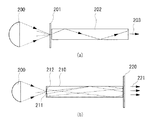
DLP方式プロジェクタは、半導体素子からなるDMDに光を照射し、その反射光をレンズ等で拡大投影して画像表示を行うものである。図9(a)に示すように、放電ランプからの光が回転楕円面鏡等のリフレクタ200によって反射され、その反射光がR、G、Bのカラーフィルターを配列した円盤状のカラーホイール201によってRGB光に順次分離される。カラーホイール201に近接されてライトトンネル202またはインテグレータ202が配置され、入射された光はそこで多重反射され均一な強度の光線束203として出射される。DMDは、RGB光に同期して時分割駆動され、画像データに従い照射された光線束203を反射させる。そして反射された光は、投影レンズを介してスクリーン上に投影される。
【0003】
上記方法とは別に、色をスクローリングさせてフルカラー映像の表示を行う方法がある。図9(b)にこの方法を示す。リフレクタ200の焦点位置近傍に、アパーチャー付きのライトトンネル210が配置される。放電ランプからの光は、アパーチャー211を介してライトトンネル210内に入射される。ライトトンネル210の出射口に近接してSCR(Sequential Color Recapture)用のカラーホイール220が配置される。
【0004】
SCR用のカラーホイール220は、その中心から半径方向にスパイラル状に延びるRGBのダイクロイックコーティングを有し、RGBコーティングを1組としたとき、これらが複数組配列されている。1組のRGBパターンは、ライトトンネル210から出射口の口径に含まれる大きさに設定される。ライトトンネル220から光線束が入射されると、カラーホイール220によってRGBの帯状の光221が出射され、カラーホイール220の回転に伴い、RGBの帯の境界が一定速度で移動される。カラーホイール220によって透過されなかった波長の光は、そこで反射されてライトトンネル210内に入射され、この光はアパーチャー211の入射部材の裏面の反射面212において反射され、再びカラーホイール220に入射される。
【0005】
図9(a)の方法と図9(b)の方法とを比較すると、図9(a)の方法では、カラーホイール201を透過する光は、放電ランプにおいて発光された光の内の約1/3であり、即ち、光源の光の利用効率は約1/3であるのに対して、図9(b)の方法は、カラーホイール220を透過する光は、放電ランプにおいて発光された光の内の約1/3であるが、カラーホイール220において反射された2/3の光が、ライトトンネル210の反射面212によって再び反射してカラーホイール220に入射され、それが再利用されるため、光の利用効率が向上され、明るい投射映像を得ることができる。
【0006】
【発明が解決しようとする課題】
しかしながら、従来のプロジェクタには、次のような課題がある。プロジェクタの使用が長期にわたると、経時変化により放電ランプの電極間のアーク長若しくはアークギャップが延びてしまう。例えば、当初のアーク長が1mmであったものが、500時間ほど使用されると、1.2〜1.3mmにまで延びることがわかっている。割合からすると、20%程度大きくなっている。放電ランプからの光を集光させたときのスポット径は、アーク長に依存するため、アーク長が延びると、集光されるスポット径も大きくなってしまう。上記の図9(b)に示すようなアパーチャー付きライトトンネル210を用いる場合、スポット径が大きくなってしまうと、その光の一部がライトトンネル210のアパーチャー211から入射されず、光の利用効率が低下してしまう。他方、アパーチャー径211をある程度大きくすることも考えられるが、アパーチャー径211が大きすぎると、反射面212の反射面積が小さくなることであり、反射面212による反射効率が低下し、SCRによるカラーホイール220を用いる利点が損なわれてしまう。
【0007】
そこで本発明は、上記従来の課題を解決し、光源の経年変化に対応することができ、光源からの光の利用効率を改善した照明光学系およびそれを用いたプロジェクタを提供することを目的とする。
さらに本発明は、光源からの入射光のスポット径に応じたアパーチャー径を選択することができる照明光学系およびそれを用いたプロジェクタを提供することを目的とする。
さらに本発明は、SCR方式により明るい投射映像を得ることができるプロジェクタを提供することを目的とする。
【0008】
【課題を解決するための手段】
本発明に係る照明光学系は、放電ランプと、前記放電ランプからの光をアパーチャーを介して入射し、所定のエリアを照明するための光を出射する光学部材と、前記光学部材へ入射される光のサイズを検出する検出手段と、前記検出手段の検出結果に応じて前記光学部材のアパーチャー径を変換するアパーチャー変換手段とを有するものである。これにより、経年変化により放電ランプのアーク長が延び、入射光のサイズが変わった場合でも最適なアパーチャーを選択し、光損失の少ない照明を行うことができる。
【0009】
本発明に係る他の照明光学系は、放電ランプと、前記放電ランプからの光を集光させる集光手段と、各々サイズが異なる複数のアパーチャーを有し、複数のアパーチャーから選択されたアパーチャーを所定位置に配置させ、前記集光手段からの光を選択されたアパーチャーに入射させる、アパーチャー変換手段と、前記アパーチャー変換手段に入射される光のサイズを検出する検出手段と、前記検出手段に基づき前記アパーチャー変換手段によって選択されるアパーチャーを制御する制御手段とを有するものである。これにより、上記と同様に、光源の経年変化に対応し光損失の少ない最適な照明を行うことができる。
【0010】
好ましくは、アパーチャー変換手段は、ロータリー式の回転円盤と、該回転円盤を回転させる回転駆動手段とを有し、前記回転円盤に複数のアパーチャーが形成される。あるいは、アパーチャー変換手段は、スライド式のスライド板と、該スライド板を移動させる移動手段とを有し、前記スライド板に複数のアパーチャーが形成されるものでも良い。
【0011】
照明光学系はさらに、各々のアパーチャーのサイズと位置との関係を示すテーブルを記憶したメモリを含み、前記制御手段は前記メモリからのテーブルを参照して前記アパーチャー変換手段を制御することが望ましい。
【0012】
本発明に係る、放電ランプからの集光された光をアパーチャーを介して入射し、入射した光により所定のエリアを照明する照明光学系における照明方法は、放電ランプからの光のサイズを検出するステップと、検出された光のサイズに応答して、複数のアパーチャーから最適な径を有するアパーチャーを選択するステップとを含む。好ましくは、検出するステップは、CCD面センサーの照射面積を検出する。
【0013】
本発明に係るプロジェクタは、上述した照明光学系と、前記照明光学系からの光を入射し選択された波長の光を透過する光透過手段と、前記光透過手段によって透過された光を変調する変調手段と、前記変調手段によって変調された光を投射する投射手段とを有する。放電ランプの経時変化に対応し、光損失を極力低減させることで、明るい投射映像を表示させることができる。
【0014】
好ましくは、光透過手段によって反射された光は、前記アパーチャーが形成されていない面によって反射され、再び前記光透過手段に入射される。例えば、アパーチャー変換手段の回転円盤の裏面は反射面である。また、光透過手段は、少なくともR、G、Bのカラーフィルターが配列されかつ回転されるカラーホイールを含む。さらに、変調手段は、DMDまたは液晶デバイスであっても良い。
【0015】
【発明の実施の形態】
以下、本発明の実施の形態について図面を参照して説明する。図1は、本発明の実施の形態に係る照明光学系の構成を示す図である。本実施の形態に係る照明光学系は、光源からの集光光線のスポット径を検出し、そのスポット径に応じた最適のアパーチャー径を選択する機能を有している。
【0016】
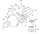
図1において、照明光学系10は、放電ランプ20と、放電ランプ20からの光を反射する反射鏡30と、反射鏡30によって集光された光線束を入射するライトトンネル40と、ライトトンネル40に近接された位置に回転可能に配置されるロータリー式のアパーチャー変換装置50と、反射鏡30とライトトンネル40との間に配置されるビームスプリッター60と、ビームスプリッター60によって反射された一部の光を受光するフォトセンサー70と、フォトセンサー70からのサイズ検出信号71を受け取り、入射光のスポット径若しくはサイズを判定し、アパーチャー変換装置50を制御する制御部80と、制御部80からの制御信号81を受けてアパーチャー変換装置50を駆動する駆動回路90とを有する。
【0017】
放電ランプ20は、例えば、キセノンランプ、メタルハライドランプ、水銀ランプ等が用いられる。放電ランプ20は、石英ガラス管内に1対の電極を有し、1対の電極は反射鏡30の光軸方向Sに一致される。一対の電極間の距離は、アーク長にほぼ等しく、集光される光線の最小サイズあるいはスポット径はこのアーク長によって決定される。
【0018】
反射鏡30は、例えば回転楕円面鏡から構成される。反射鏡30の中心部に開口が形成され、この開口内に放電ランプ20の一端部が一体に取り付けられる。
放電ランプ20の電極間の中央、言い換えればアークの発光点が反射鏡30の焦点位置に一致される。放電ランプ20から発光された光は、反射鏡30によって反射され、その反射光は第2の焦点位置に向けて集光される。
【0019】
反射鏡30からの光が集光される位置近傍にライトトンネル40が配置される。ライトトンネル40は、その軸方向と直交する断面が矩形状を有する中空のガラス部材であり、入射口41、出射口42、それらの間の光伝送部分43とを有する。ライトトンネル40の軸方向の中心は、反射鏡30の光軸Sと一致する。
入射口41に入射された光は、光伝送部分43の内壁で多重反射され、出射口42からほぼ均一な強度の光線束が出射される。出射口42からの光線束は、そのアスペクト比に応じた口径の大きさの光となって所望の領域を照射する。
【0020】
アパーチャー変換装置50はライトトンネル40の入射口41の近傍に配置される。該変換装置50は、複数のアパーチャーが形成されたロータリー式の回転円盤51と、回転円盤51の回転中心軸に結合されたモータ(図中省略)とを有する。モータは、例えばステッピングモータが用いられ、これは駆動回路90によって駆動される。回転円盤51の円周方向には、それぞれサイズの異なる円形状のアパーチャー52a、52b、52c、52dが形成され、これらのアパーチャーはそれぞれ等しい間隔、例えば45度の間隔に配置される。アパーチャー52a、52b、52c、52dの各半径を、ra、rb、rc、rdとすると、ra<rb<rc<rdの関係にある。好ましくは、放電ランプ20のアーク長の動的な延びに細かく対応することができるように、rd=1.05×rc、rc=1.05×rb、rb=1.05×raのように、半径が5%ずつの割合で大きくなるように設定される。また、半径の一番小さいraの値は、放電ランプ20のアーク長が初期状態(一番短いとき)にあるときに入射光を通過させることができるように設定される。アパーチャー52a、52b、52c、52dの位置と、それらの半径ra、rb、rc、rdとの関係は、図2に示すようなテーブルとしてアパーチャー径メモリ82に記憶される。
【0021】
モータは、駆動回路90からのパルス信号に応じて回転円盤51を一定の回転角だけ回転させ、アパーチャー52a、52b、52c、52dのいずれかの中心をライトトンネル40の軸に一致させる。また、回転円盤51の裏面には、後述するように、反射膜がコーティングされ、裏面は反射面として機能することができる。
【0022】
反射鏡30とアパーチャー変換装置50との間に所定の角度に傾斜されたビームスプリッター60が介在される。ビームスプリッター60は、公知のように入射光線束を二つに分ける光学素子である。反射鏡30からの光は、その大部分がビームスプリッター60を透過して回転円盤51に入射されるが、残り数%の光がビームスプリッター60によって反射され、フォトセンサー70に受光される。
【0023】
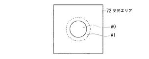
フォトセンサー70は、例えば、2次元的な受光面を有するCCD面センサーであり、受光した光を電気信号に変換する。図3にフォトセンサー70の受光エリア72と入射光のサイズとの関係を示す。放電ランプ20の使用開始時(t0)、受光エリア72の照射面積をA0とする。t1時間経過後、アーク長が延び、その時の照射面積をA1とする。照射面積A0、A1は、照射されたCCDの合計の画素数であり、この画素数に対応した電気信号が、サイズ検出信号71としてフォトセンサー70から制御部80に出力される。フォトセンサー70の受光エリア72に照射されるスポット径が、回転円盤51の集光面のスポット径と同じ大きさになるように、フォトセンサー70が配置される。つまり、放電ランプ20から回転円盤51までの光路長と、放電ランプ20からフォトセンサー70の受光エリア72までの光路長を等しくし、それぞれの入射光のスポット径が一対一に対応するようにする。こうすることで、制御部80は、受光エリア72の照射面積から、集光面である回転円盤51への入射光のスポット径を判定することができる。
【0024】
放電ランプ20の使用開始時(t0)、制御部80は、メモリ82に記憶されたアパーチャー径のテーブルを参照し、一番小さな半径raであるアパーチャー52aがライトトンネル40の入射口41に整合されるように、初期設定をする。この初期設定がなされた状態において、放電ランプ20から反射鏡30を介してアパーチャー変換装置50に光が入射されるとき、入射光のすべてがアパーチャー52aを通過し、ライトトンネル40に入射される。
【0025】
放電ランプをt1時間使用した後、そのアーク長が延びると、受光エリア72の照射面積がA0からA1に変化する(図3参照)。このとき、アパーチャー変換装置50へ入射された光のスポット径がアパーチャー52aの径(2ra)よりも大きいと、入射光の一部がアパーチャー52aを通過することができず、外部に反射されてしまう。制御部80は、フォトセンサー70からのサイズ検出信号71に基づき、照射面積A1すなわち入射光のスポット径を算出する。制御部80は、メモリ82のテーブルを参照し、入射光のスポット径(サイズ)よりも大きくかつそれに最も近い径を有するアパーチャーを最適なアパーチャーと判定し、その最適なアパーチャーがライトトンネル40の入射口に位置決めされるように駆動回路90を制御する。
【0026】
このように、制御部80は、フォトセンサー70からのサイズ検出信号71をモニターすることで、入射光のサイズを判定し、入射光に最適なアパーチャー径を選択するように駆動回路90を制御する。これにより、入射光のすべてがアパーチャーを介してライトトンネル40に入射され、光の利用効率の低下が抑制される。
【0027】
図4に本発明の第2の実施の形態の例を示す。第2の実施の形態に係る照明光学系10aは、アパーチャー変換装置50aの構成を除き、他の構成は第1の実施の態様と同じである。アパーチャー変換装置50aは、スライド可能なスライド板51aを有し、スライド板51aの長手方向に、それぞれ径の異なるアパーチャー52a、52b、52c、52dが形成されている。これらのアパーチャーの位置とサイズの関係は第1の実施の態様のときと同じようにメモリ82に記憶される。スライド板51aは、図示しないリードネジに螺合され、リードネジをモータにより回転させることで、水平方向に移動される。第2の実施の態様は、ロータリー式を用いる代わりにスライド式によりアパーチャーの変換を行うものである。
【0028】
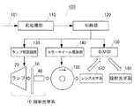
次に、第1の実施の態様に係る照明光学系をプロジェクタに適用した例を示す。図5は、DLP方式プロジェクタの主要な構成を示すブロック図である。プロジェクタ100は、画像信号101を入力し、これをDMDと同じ画素数のRGBデジタル画像データに変換する前処理部110と、前処理部110からのデジタル画像データに基づきDMD150の駆動を制御するとともにランプ駆動回路130及びカラーホイール駆動部140等の制御を行う制御部120とを有する。ランプ駆動回路130は、放電ランプ20の起動及び起動後の放電ランプのAC駆動を制御する。カラーホイール駆動部140は、カラーホイール160を回転させ、放電ランプ20からアパーチャー変換装置50およびライトトンネル40を介して入射された光をRGBに分離させる。レンズ光学系170は、カラーホイール160からのRGB光をコンデンサレンズやミラーを介してDMD150の画像領域を照明する。DMD150は、各画素に相当するミラーをアレイ状に配置させ、それらのミラーをスイッチングさせて入射光を反射させる。投射光学系180は、DMD150からの反射光を拡大投射しスクリーン上に画像を表示させる。ここで、放電ランプ20、ライトトンネル40およびアパーチャー変換装置50は、第1の実施の形態に係る照明光学系10(図1)に相当する。
【0029】
図6に放電ランプからカラーホイールに至る光学系を示す。放電ランプ20からの集光された光は、アパーチャー変換装置50を介してライトトンネル40の入射口41に入射され、光伝送路部分43の内壁を多重反射され、その出射口42から出射され、カラーホイール160に入射される。アパーチャー変換装置50の回転円盤51とライトトンネル40の入射口41との距離はできる限り小さいことが望ましく、理想的には両者が実質上密着するぐらいに近接される。また、アパーチャー変換装置50のアパーチャー52aの中心は、ライトトンネル40の軸方向の中心と一致する。回転円盤51の裏面には、反射膜がコーティングされ反射面55が形成されている。反射面55は、後述するカラーホイール160から反射されてライトトンネル40内に入射されてきた光を反射させる。
【0030】
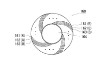
図7に、SCR用カラーホイールの構成例を示す。SCR用カラーホイール160は、ガラス円盤上にスパイラル状に配列されたR、G、Bの帯状のダイクロイックコーティング161、162、163を有する。R、G、Bのダイクロイックミラー161、162、163を一組とするパターンが、ホイールの中心から外周に向けて複数配列される。中心の開口164は、駆動モータの回転軸と結合される部分である。
【0031】
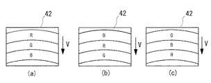
R、G、Bの帯状のコーティング161、162、163は、ライトトンネル40の出射口42内に含まれる大きさに設定される必要がある。図8に出射口の大きさとRGBの大きさとの関係を示す。ライトトンネル40の出射口42には、一組のR、G、Bのコーティング161、162、163が含まれる。これにより、カラーホイール160に出射口42の光線束が入射されると、そこから帯状のR、G、B光が透過される。カラーホイール160が一定速度で回転されると、図8(a)、(b)、(c)に示すように、RGBの境界が一定速度Vで移動する。
【0032】
図6に戻って、ライトトンネル40の出射口42に近接してカラーホイール160が位置決めされる。ライトトンネル40の出射口42からカラーホイール160に入射された光のうち、Rのカラーフィルター161においてRが透過され、それ以外の波長の光がそこで反射される。同様にG、Bのフィルター162、163においてG、Bの光が透過され、それ以外の波長の光が反射される。つまり、約1/3の光がカラーホイール160を透過され、約2/3の光がそこで反射される。反射された光はライトトンネル40の出射口42から光伝送部分43に入射され、それらの光がアパーチャー変換装置50の回転円盤51の反射面55によって反射されて再び入射口41に入射され、さらに出射口42から出射されてカラーホイール160に再び入射される。
【0033】
放電ランプ20の経時変化によりアーク長が延び、入射光のスポット径が大きくなると、アパーチャー変換装置50が最適なアパーチャー径を選択する。これにより、放電ランプ20からの光がアパーチャーによって遮断されることなく、ライトトンネル40内に入射される。回転円盤51の裏面の反射面55の反射効率を考えると、アパーチャー径をできるだけ小さくし、反射面55の面積を大きくすることが有効であるが、本実施の形態のように、入射光のサイズに応じた最適なアパーチャー径を選択することで、放電ランプ20からの入射光の損失を低減しかつカラーホイール160からの入射光の反射効率の低減を抑制するということを同時に達成することができる。
【0034】
以上、本発明の好ましい実施の形態について詳述したが、本発明は係る特定の実施形態に限定されるものではなく、特許請求の範囲に記載された本発明の要旨の範囲内において、種々の変形・変更が可能である。
【0035】
上記実施の態様は、DLP方式のプロジェクタを例に説明したが、勿論、これ以外の液晶デバイスを用いたプロジェクタや、リア投射型のプロジェクタ等に広く適用することができる。
【0036】
さらに上記実施の態様では、サイズの異なるアパーチャーを4つ示したが、アパーチャーのサイズ、形状、数は、設計事情に合わせて当業者によって適宜選択される。
【0037】
さらに、フォトセンサー70の受光エリアの入射スポット径と、アパーチャー変換装置の回転円盤の入射スポット径とが同じとなるような関係に光路長を設定したが、これに限らず、両者のスポット径は異なるものであっても良い。例えば、両者のスポット径の大きさが、1:nの関係にし、その関係の基づき最適なアパーチャーを選択しても良い。
【0038】
さらに上記実施の態様では、光伝送部材として内部に空間が形成されたライトトンネルを例に説明したが、これ以外の形状のライトトンネルや他のインテグレータを用いてもよい。ライトトンネル等の光伝送部材の断面形状、大きさ、材質等は、使用されるプロジェクタの環境、大きさ、設計状態等に応じて当業者であれば容易に変更することができる。
【0039】
【発明の効果】
本発明の照明光学系によれば、放電ランプのアーク長が経時変化により延び、それによって集光面における入射光のサイズ(あるいはスポット径)が変わった場合でも、その入射光のサイズに最適なアパーチャーを選択することで、放電ランプからの光の損失を極力低減し、光利用効率の低下を抑制することができる。
さらに、このような照明光学系を用いたプロジェクタでは、経時変化に伴う明るさの低下を極力低減することが可能となる。特に、SCRによるプロジェクタの場合には、入射光に応じたアパーチャー径を選択できるようにすることで、カラーホイールからの光を反射する反射面の反射効率の低減を抑制することが可能となる。
【図面の簡単な説明】
【図1】本発明の第1の実施の形態に係る照明光学系の構成を示す図である。
【図2】アパーチャー径の位置をサイズの関係を示すテーブルである。
【図3】受光エリアと照射面積との関係を示す図である。
【図4】本発明の第2の実施の形態に係る照明光学系の構成を示す図である。
【図5】本実施の形態の照明光学系を適用したプロジェクタの構成を示すブロック図である。
【図6】放電ランプからカラーホイールまでの光学系を示す図である。
【図7】カラーホイールの構成を示す図である。
【図8】カラーホイールから透過される光を示す図である。
【図9】従来の照明光学系を示す図である。
【符号の説明】
10:照明光学系 20:放電ランプ
30:反射鏡 40:ライトトンネル
50:アパーチャー変換装置 51:回転円盤
52a、52b、52c、52d:アパーチャー
55:反射面 60:ビームスプリッター
70:フォトセンサー 72:受光エリア
80:制御部 82:メモリ
90:駆動回路 100:プロジェクタ
150:DMD 160:カラーホイール
170:レンズ光学系 180:投射光学系[0001]
TECHNICAL FIELD OF THE INVENTION
The present invention relates to a projector, and more particularly, to a DLP (Digital Light Processing) using DMD (Digital Mirror Device): DLP is a projector of Texas Instruments, Inc., and a lighting optical system thereof.
[0002]
[Prior art]
The DLP type projector irradiates light to a DMD made of a semiconductor element, and enlarges and projects the reflected light with a lens or the like to display an image. As shown in FIG. 9A, light from a discharge lamp is reflected by a
[0003]
Apart from the above method, there is a method of displaying a full-color image by scrolling colors. FIG. 9B illustrates this method. A
[0004]
The
[0005]
When comparing the method of FIG. 9A and the method of FIG. 9B, in the method of FIG. 9A, the light transmitted through the
[0006]
[Problems to be solved by the invention]
However, the conventional projector has the following problems. If the projector is used for a long period of time, the arc length or the arc gap between the electrodes of the discharge lamp will increase due to aging. For example, it has been found that the initial arc length was 1 mm, but it has been extended to 1.2 to 1.3 mm when used for about 500 hours. The ratio is about 20% larger. Since the spot diameter when condensing light from the discharge lamp depends on the arc length, if the arc length increases, the converged spot diameter also increases. In the case of using the
[0007]
Accordingly, an object of the present invention is to provide an illumination optical system capable of solving the above-described conventional problems, responding to aging of the light source, improving the use efficiency of light from the light source, and a projector using the same. I do.
Still another object of the present invention is to provide an illumination optical system capable of selecting an aperture diameter according to a spot diameter of incident light from a light source, and a projector using the same.
Still another object of the present invention is to provide a projector capable of obtaining a bright projection image by the SCR method.
[0008]
[Means for Solving the Problems]
An illumination optical system according to the present invention includes a discharge lamp, an optical member that receives light from the discharge lamp via an aperture, and emits light for illuminating a predetermined area, and is incident on the optical member. A detecting unit for detecting a size of light; and an aperture converting unit for converting an aperture diameter of the optical member according to a detection result of the detecting unit. Thereby, even when the arc length of the discharge lamp is extended due to aging and the size of the incident light is changed, the optimal aperture can be selected and illumination with less light loss can be performed.
[0009]
Another illumination optical system according to the present invention includes a discharge lamp, a condensing unit that condenses light from the discharge lamp, and a plurality of apertures having different sizes, and an aperture selected from the plurality of apertures. Arranged at a predetermined position, the light from the light condensing means is incident on a selected aperture, aperture conversion means, detection means for detecting the size of light incident on the aperture conversion means, based on the detection means Control means for controlling the aperture selected by the aperture conversion means. Thus, in the same manner as described above, it is possible to perform optimal illumination with little light loss corresponding to aging of the light source.
[0010]
Preferably, the aperture converting means has a rotary type rotating disk and a rotation driving means for rotating the rotating disk, and a plurality of apertures are formed on the rotating disk. Alternatively, the aperture conversion unit may include a slide type slide plate and a moving unit for moving the slide plate, and a plurality of apertures may be formed on the slide plate.
[0011]
It is preferable that the illumination optical system further includes a memory storing a table indicating a relationship between a size and a position of each aperture, and the control unit controls the aperture conversion unit with reference to the table from the memory.
[0012]
An illumination method in an illumination optical system according to the present invention in which light condensed from a discharge lamp is incident through an aperture and illuminates a predetermined area with the incident light detects a size of light from the discharge lamp. And selecting an aperture having an optimal diameter from the plurality of apertures in response to the detected light size. Preferably, the detecting step detects an irradiation area of the CCD surface sensor.
[0013]
A projector according to the present invention includes the above-described illumination optical system, a light transmission unit that receives light from the illumination optical system and transmits light having a selected wavelength, and modulates light transmitted by the light transmission unit. A modulating means; and a projecting means for projecting the light modulated by the modulating means. A bright projection image can be displayed by reducing the light loss as much as possible in response to the aging of the discharge lamp.
[0014]
Preferably, the light reflected by the light transmitting means is reflected by a surface on which the aperture is not formed, and is incident on the light transmitting means again. For example, the back surface of the rotating disk of the aperture conversion means is a reflection surface. Further, the light transmitting means includes a color wheel on which at least R, G, and B color filters are arranged and rotated. Further, the modulating means may be a DMD or a liquid crystal device.
[0015]
BEST MODE FOR CARRYING OUT THE INVENTION
Hereinafter, embodiments of the present invention will be described with reference to the drawings. FIG. 1 is a diagram showing a configuration of an illumination optical system according to an embodiment of the present invention. The illumination optical system according to the present embodiment has a function of detecting a spot diameter of a condensed light beam from a light source and selecting an optimal aperture diameter according to the spot diameter.
[0016]
In FIG. 1, an illumination
[0017]
As the
[0018]
The reflecting
The center between the electrodes of the
[0019]
A
The light incident on the
[0020]
The
[0021]
The motor rotates the
[0022]
A
[0023]
The
[0024]
At the start of use of the discharge lamp 20 (t0), the
[0025]
When the arc length increases after the discharge lamp has been used for t1 time, the irradiation area of the
[0026]
As described above, the
[0027]
FIG. 4 shows an example of the second embodiment of the present invention. The configuration of the illumination
[0028]
Next, an example in which the illumination optical system according to the first embodiment is applied to a projector will be described. FIG. 5 is a block diagram showing a main configuration of the DLP system projector. The
[0029]
FIG. 6 shows an optical system from the discharge lamp to the color wheel. The condensed light from the
[0030]
FIG. 7 shows a configuration example of an SCR color wheel. The
[0031]
The R, G, and B strip-shaped
[0032]
Returning to FIG. 6, the
[0033]
When the arc length increases due to the temporal change of the
[0034]
As described above, the preferred embodiments of the present invention have been described in detail. However, the present invention is not limited to the specific embodiments, and various modifications may be made within the scope of the present invention described in the appended claims. Deformation and modification are possible.
[0035]
The above embodiment has been described by taking the DLP type projector as an example. However, it is needless to say that the present invention can be widely applied to projectors using other liquid crystal devices, rear projection type projectors, and the like.
[0036]
Further, in the above embodiment, four apertures having different sizes are shown, but the size, shape, and number of the apertures are appropriately selected by those skilled in the art according to design circumstances.
[0037]
Further, the optical path length is set such that the incident spot diameter of the light receiving area of the
[0038]
Further, in the above embodiment, the light tunnel in which the space is formed has been described as an example of the light transmission member, but a light tunnel having another shape or another integrator may be used. Those skilled in the art can easily change the cross-sectional shape, size, material, and the like of the light transmission member such as the light tunnel according to the environment, size, design state, and the like of the projector to be used.
[0039]
【The invention's effect】
According to the illumination optical system of the present invention, even when the arc length of the discharge lamp is increased with the lapse of time and thereby the size (or spot diameter) of the incident light on the light-collecting surface is changed, the arc length optimal for the incident light is obtained. By selecting the aperture, loss of light from the discharge lamp can be reduced as much as possible, and a decrease in light use efficiency can be suppressed.
Further, in a projector using such an illumination optical system, it is possible to minimize a decrease in brightness due to aging. In particular, in the case of a projector based on the SCR, by making it possible to select an aperture diameter according to incident light, it is possible to suppress a reduction in the reflection efficiency of a reflection surface that reflects light from a color wheel.
[Brief description of the drawings]
FIG. 1 is a diagram showing a configuration of an illumination optical system according to a first embodiment of the present invention.
FIG. 2 is a table showing a relationship between a position of an aperture diameter and a size.
FIG. 3 is a diagram showing a relationship between a light receiving area and an irradiation area.
FIG. 4 is a diagram showing a configuration of an illumination optical system according to a second embodiment of the present invention.
FIG. 5 is a block diagram showing a configuration of a projector to which the illumination optical system according to the embodiment is applied.
FIG. 6 is a diagram showing an optical system from a discharge lamp to a color wheel.
FIG. 7 is a diagram illustrating a configuration of a color wheel.
FIG. 8 is a diagram showing light transmitted from a color wheel.
FIG. 9 is a diagram showing a conventional illumination optical system.
[Explanation of symbols]
10: Illumination optical system 20: Discharge lamp 30: Reflector 40: Light tunnel 50: Aperture converter 51: Rotating
Claims (14)
前記放電ランプからの光をアパーチャーを介して入射し、所定のエリアを照明するための光を出射する光学部材と、
前記光学部材へ入射される光のサイズを検出する検出手段と、
前記検出手段の検出結果に応じて前記光学部材のアパーチャー径を変換するアパーチャー変換手段とを有する、照明光学系。A discharge lamp,
An optical member that receives light from the discharge lamp through an aperture and emits light for illuminating a predetermined area,
Detecting means for detecting the size of light incident on the optical member,
An aperture conversion unit configured to convert an aperture diameter of the optical member according to a detection result of the detection unit.
前記放電ランプからの光を集光させる集光手段と、
各々サイズが異なる複数のアパーチャーを有し、複数のアパーチャーから選択されたアパーチャーを所定位置に配置させ、前記集光手段からの光を選択されたアパーチャーに入射させる、アパーチャー変換手段と、
前記アパーチャー変換手段に入射される光のサイズを検出する検出手段と、
前記検出手段に基づき前記アパーチャー変換手段によって選択されるアパーチャーを制御する制御手段と、を有する照明光学系。A discharge lamp,
Light collecting means for collecting light from the discharge lamp,
Aperture conversion means, each having a plurality of apertures having different sizes, arranging apertures selected from the plurality of apertures at predetermined positions, and causing light from the light condensing means to enter the selected apertures,
Detection means for detecting the size of light incident on the aperture conversion means,
A control unit for controlling an aperture selected by the aperture conversion unit based on the detection unit.
放電ランプからの光のサイズを検出するステップと、
検出された光のサイズに応答して、複数のアパーチャーから最適なアパーチャーを選択するステップと、を含む照明方法。An illumination method in an illumination optical system that illuminates a predetermined area with the incident light by entering the light collected from the discharge lamp through an aperture,
Detecting the size of the light from the discharge lamp;
Selecting an optimal aperture from the plurality of apertures in response to the detected light size.
Priority Applications (1)
| Application Number | Priority Date | Filing Date | Title |
|---|---|---|---|
| JP2003025785A JP2004239934A (en) | 2003-02-03 | 2003-02-03 | Illumination optical system and projector using the same |
Applications Claiming Priority (1)
| Application Number | Priority Date | Filing Date | Title |
|---|---|---|---|
| JP2003025785A JP2004239934A (en) | 2003-02-03 | 2003-02-03 | Illumination optical system and projector using the same |
Publications (1)
| Publication Number | Publication Date |
|---|---|
| JP2004239934A true JP2004239934A (en) | 2004-08-26 |
Family
ID=32953984
Family Applications (1)
| Application Number | Title | Priority Date | Filing Date |
|---|---|---|---|
| JP2003025785A Pending JP2004239934A (en) | 2003-02-03 | 2003-02-03 | Illumination optical system and projector using the same |
Country Status (1)
| Country | Link |
|---|---|
| JP (1) | JP2004239934A (en) |
Cited By (4)
| Publication number | Priority date | Publication date | Assignee | Title |
|---|---|---|---|---|
| JP2007047337A (en) * | 2005-08-09 | 2007-02-22 | Hitachi Ltd | Projection-type video display device |
| JP2012159552A (en) * | 2011-01-31 | 2012-08-23 | Mitsubishi Electric Corp | Video display device and light guide module |
| US9395607B2 (en) | 2013-06-10 | 2016-07-19 | Ricoh Company, Ltd. | Image projection apparatus including a shield |
| CN110531567A (en) * | 2018-05-24 | 2019-12-03 | 斯坦雷电气株式会社 | Lighting device, light projection system |
-
2003
- 2003-02-03 JP JP2003025785A patent/JP2004239934A/en active Pending
Cited By (5)
| Publication number | Priority date | Publication date | Assignee | Title |
|---|---|---|---|---|
| JP2007047337A (en) * | 2005-08-09 | 2007-02-22 | Hitachi Ltd | Projection-type video display device |
| JP2012159552A (en) * | 2011-01-31 | 2012-08-23 | Mitsubishi Electric Corp | Video display device and light guide module |
| US9395607B2 (en) | 2013-06-10 | 2016-07-19 | Ricoh Company, Ltd. | Image projection apparatus including a shield |
| CN110531567A (en) * | 2018-05-24 | 2019-12-03 | 斯坦雷电气株式会社 | Lighting device, light projection system |
| CN110531567B (en) * | 2018-05-24 | 2022-09-13 | 斯坦雷电气株式会社 | Illumination device and light projection system |
Similar Documents
| Publication | Publication Date | Title |
|---|---|---|
| US8926098B2 (en) | Illumination system and projection apparatus | |
| JP6452172B2 (en) | Illumination device, wheel deterioration detection method, and projector | |
| JP5500341B2 (en) | Light source unit and projector | |
| JP5656058B2 (en) | Light emitting unit and projector | |
| JP2007156270A (en) | Light source device and projection-type image display device | |
| KR20030076442A (en) | Digital mirror device projector and method of controlling amount of light being used in digital mirror device projector | |
| JP2014056074A (en) | Illumination light source device, projector equipped with the illumination light source device, and control method for the projector | |
| JP2011128521A (en) | Light source device and projector | |
| JP2011221502A (en) | Projection type video display apparatus and light source device | |
| US20080239248A1 (en) | Display illumination apparatus | |
| JP2011070882A (en) | Light source device and projector including the same | |
| WO2013102358A1 (en) | Light-emitting device and projection apparatus | |
| JP5783272B2 (en) | Light emitting unit and projector | |
| JP4998785B2 (en) | Light source device and projector | |
| JP2004252112A (en) | Video projection device and illuminator used therefor | |
| JP2004239933A (en) | Illumination optical system and projector using the same | |
| JP5445854B2 (en) | Light emitting unit and projector | |
| JP2004239934A (en) | Illumination optical system and projector using the same | |
| TWI354180B (en) | Light source system and display apparatus comprisi | |
| JP2012137558A (en) | Color wheel unit and projection type display device | |
| JP2003307705A (en) | Illumination optical system and projector using the same | |
| US8491133B2 (en) | Projection apparatus | |
| JP2004212726A (en) | Optical transmission member with heat sink, and projector using same | |
| JP2005156607A (en) | Color separation device and projector | |
| JP2016004051A (en) | Light source device and projection display device |