EP2816298A1 - Attachment member for attaching objects to an underlying construction element - Google Patents
Attachment member for attaching objects to an underlying construction element Download PDFInfo
- Publication number
- EP2816298A1 EP2816298A1 EP14002130.4A EP14002130A EP2816298A1 EP 2816298 A1 EP2816298 A1 EP 2816298A1 EP 14002130 A EP14002130 A EP 14002130A EP 2816298 A1 EP2816298 A1 EP 2816298A1
- Authority
- EP
- European Patent Office
- Prior art keywords
- attachment
- connection member
- connection
- attachment member
- contact surface
- Prior art date
- Legal status (The legal status is an assumption and is not a legal conclusion. Google has not performed a legal analysis and makes no representation as to the accuracy of the status listed.)
- Granted
Links
Images







Classifications
-
- F—MECHANICAL ENGINEERING; LIGHTING; HEATING; WEAPONS; BLASTING
- F24—HEATING; RANGES; VENTILATING
- F24S—SOLAR HEAT COLLECTORS; SOLAR HEAT SYSTEMS
- F24S25/00—Arrangement of stationary mountings or supports for solar heat collector modules
- F24S25/60—Fixation means, e.g. fasteners, specially adapted for supporting solar heat collector modules
- F24S25/61—Fixation means, e.g. fasteners, specially adapted for supporting solar heat collector modules for fixing to the ground or to building structures
-
- F—MECHANICAL ENGINEERING; LIGHTING; HEATING; WEAPONS; BLASTING
- F24—HEATING; RANGES; VENTILATING
- F24S—SOLAR HEAT COLLECTORS; SOLAR HEAT SYSTEMS
- F24S25/00—Arrangement of stationary mountings or supports for solar heat collector modules
- F24S25/60—Fixation means, e.g. fasteners, specially adapted for supporting solar heat collector modules
- F24S2025/6005—Fixation means, e.g. fasteners, specially adapted for supporting solar heat collector modules by screwed connection
-
- F—MECHANICAL ENGINEERING; LIGHTING; HEATING; WEAPONS; BLASTING
- F24—HEATING; RANGES; VENTILATING
- F24S—SOLAR HEAT COLLECTORS; SOLAR HEAT SYSTEMS
- F24S25/00—Arrangement of stationary mountings or supports for solar heat collector modules
- F24S25/60—Fixation means, e.g. fasteners, specially adapted for supporting solar heat collector modules
- F24S2025/6006—Fixation means, e.g. fasteners, specially adapted for supporting solar heat collector modules by using threaded elements, e.g. stud bolts
-
- Y—GENERAL TAGGING OF NEW TECHNOLOGICAL DEVELOPMENTS; GENERAL TAGGING OF CROSS-SECTIONAL TECHNOLOGIES SPANNING OVER SEVERAL SECTIONS OF THE IPC; TECHNICAL SUBJECTS COVERED BY FORMER USPC CROSS-REFERENCE ART COLLECTIONS [XRACs] AND DIGESTS
- Y02—TECHNOLOGIES OR APPLICATIONS FOR MITIGATION OR ADAPTATION AGAINST CLIMATE CHANGE
- Y02B—CLIMATE CHANGE MITIGATION TECHNOLOGIES RELATED TO BUILDINGS, e.g. HOUSING, HOUSE APPLIANCES OR RELATED END-USER APPLICATIONS
- Y02B10/00—Integration of renewable energy sources in buildings
- Y02B10/20—Solar thermal
-
- Y—GENERAL TAGGING OF NEW TECHNOLOGICAL DEVELOPMENTS; GENERAL TAGGING OF CROSS-SECTIONAL TECHNOLOGIES SPANNING OVER SEVERAL SECTIONS OF THE IPC; TECHNICAL SUBJECTS COVERED BY FORMER USPC CROSS-REFERENCE ART COLLECTIONS [XRACs] AND DIGESTS
- Y02—TECHNOLOGIES OR APPLICATIONS FOR MITIGATION OR ADAPTATION AGAINST CLIMATE CHANGE
- Y02E—REDUCTION OF GREENHOUSE GAS [GHG] EMISSIONS, RELATED TO ENERGY GENERATION, TRANSMISSION OR DISTRIBUTION
- Y02E10/00—Energy generation through renewable energy sources
- Y02E10/40—Solar thermal energy, e.g. solar towers
- Y02E10/47—Mountings or tracking
Definitions
- the present invention generally relates to an attachment member for attaching one or more objects to an underlying construction element.
- the present invention more particularly relates to an attachment member configured to secure solar panels e.g. solar photovoltaic panels or solar mounts to one or more underlying construction elements such as a rafter or a concrete deck.
- Mounting of items such as solar panels to a roof covered with roofing felt requires special mounts or brackets configured to receive the mounting rail onto which the solar panels have to be secured. During the mounting process it is of great importance that the areas in which the roofing felt is penetrated is sealed in order to prevent water ingress.
- brackets or mounts suitable for being used to install solar panels and other objects on an insulated roof It is an object of the present invention to specify an attachment member that is cheaper to produce than the existing types of brackets and mounts for installation of solar panels and mounting rails. It is also an object of the present invention to provide an attachment member suitable for being secured to an isolated roof.
- the attachment member is an attachment member for attaching one or more objects such as mounting rails for solar panels to an underlying construction element such as a rafter or a concrete deck, where the attachment member comprises a massive or semi-massive connection member having a longitudinal axis and an upper end and a lower end, where: a) at least one lower attachment element configured to be mounted in the underlying construction element is attached to the connection member or b) or where means for mounting one or more means for attachment into the underlying construction element are provided in the connection member, where a mount or bracket configured for mounting objects such as a mounting rails for attachment of solar panels or a unit for attachment of a mount or a bracket for mounting of objects such as a mounting rails for attachment of solar panels are attached to the upper portion of the connection member, wherein the connection member is configured to transfer load from the mount, the bracket or the unit for attachment of the mount or bracket to the at least one lower attachment element, where the connection member comprises a lower connection surface extending basically perpendicular to the longitudinal axis of
- the attachment member may be used to mount mounting rails for attachment of solar panels to an underlying roof, including rafters, plywood, boards or concrete.
- the attachment member may be used to mount ventilation devices, rood arrangements in general including guiding rails and the like.
- connection member is massive since it may reduce the production costs and make it easier to manufacture the attachment member.
- the attachment member may be moulded in plastic by means of e.g. injection moulding or extrusion or cutting.
- the lower attachment element may be made in metal e.g. stainless steel. It may be beneficial that the lower attachment element is shaped as a screw or another element suitable for being attached to wood or stoe or concrete.
- the lower attachment element may be any suitable type of screw including a lag screw, a twinfast screw, an anchor bolt, a self-drilling screw or any other suitable type of attachment element.
- Attachment of the attachment element to the connection member may be carried out by any suitable means e.g. moulding, gluing or mechanical attachment e.g. by screwing.
- connection member is massive or almost massive.
- connection member configured to transfer load from the mount, the bracket or the unit for attachment of the mount or bracket to the at least one lower attachment element
- connection member comprises a lower connection surface extending basically perpendicular to the longitudinal axis of the connection member, where the lower connection surface is configured to bear against the underlying construction element and hereby provide a stabilising lower connection surface when the attachment member is mounted to the underlying construction element.
- the at least one lower attachment element protrudes from the lower connection surface and extends along the longitudinal axis of the connection member it is possible to ensure a firm attachment of the attachment member.
- connection member is a massive member made in plastic, where at least one lower attachment element shaped as a tapered rod member, preferably a threaded metal rod.
- Such attachment member provides a fast and easy mounting of the attachment member.
- connection member comprises an upper planar connection surface extending basically perpendicular to the longitudinal axis of the connection member.
- connection member comprises an upper planar contact surface angled between 45 and 90 grader relative to the longitudinal axis of the connection member. Hereby it is possible to angle the objects relative to horizontal.
- connection member comprises an upper planar contact surface angled between 60 and 80 grader relative to the longitudinal axis of the connection member so that solar panels may be mounted 10-30 degrees relative to an underlying roof (e.g. a horizontal roof).
- underlying roof e.g. a horizontal roof
- connection member comprises a cylindrical portion and comprises a planar circular upper contact surface and a planar lower contact surface. Such construction is cheap, easy to produce and strong.
- connection member comprises a rectangular, preferably square cross section and comprises a planar and rectangular, preferably square upper contact surface and a planar rectangular, preferably square lower contact surface extending basically parallel to the upper contact surface, where a plurality of bores are provided in the connection member, through which bores the attachment member is configured to be attached to the underlying construction element.
- Such connection member is easy to seal when mounting it on roofing felt.
- connection member comprises a rectangular, preferably square cross section and comprises a planar and rectangular, preferably square upper contact surface and a planar rectangular, preferably square lower contact surface extending basically parallel to the upper contact surface, where a plurality of through-going bores are provided in the connection member, through which through-going bores the attachment member is configured to be attached to the underlying construction element.
- a centrally arranged mount or bracket is attached to connection member, where the mount or bracket is attached to a threaded rod, which threaded rod is moulded or mechanically attached to the connection member.
- Such construction is simple and strong.
- a first bore is provided in the upper portion of the connection member and a lower bore is provided in the connection member, where the two bores extend basically parallel to the longitudinal axis of the connection member, where an upper attachment element is formed as a threaded rod is mounted in the first bore.
- an upper attachment element is formed as a threaded rod is mounted in the first bore.
- the lower attachment element is formed as a threaded rod and is mounted in the second bore.
- connection member It may be advantageous that a through-going bore is provided in the connection member and that a through-going rod member extends through the through-going bore and is attached to the connection member. Such construction is easy to produce, strong and reliable.
- the rod member is a threaded rod member. Hereby it is possible to provide a firm attachment.
- attachment member is configured to upon rotation of the threaded rod member adjust the position of the mount or bracket relative to the connection member. Hereby adjustment may be provided.
- the attachment member is configured to upon rotation of the threaded rod member adjust the distance from the connection member to the distal end of the lower attachment element being shaped as a threaded rod member.
- a recess configured to receive and contain a flexible sealing member is provided at the periphery at the lower portion of the connection member.
- a recess configured to receive and contain a flexible sealing member is provided at the periphery at the lower portion of the connection member.
- attachment member is configured to be mounted directly into soil, sand or gravel.
- connection member comprises a plurality of spikes protruding from the lower contact surface.
- the connection member comprises a plurality of spikes protruding from the lower contact surface.
- it is possibly to glue the attachment member to a roof in an easier manner.
- the spikes will prevent the attachment member from skidding.
- connection member is provided with a plurality of bores and a plurality of bung members configured to be attachably inserted into the bores, where the bung members comprises a spike protruding from the bung members.
- the connection member is provided with a plurality of bores and a plurality of bung members configured to be attachably inserted into the bores, where the bung members comprises a spike protruding from the bung members.
- the bung members are conical and the bores are cylindrical.
- the bung members may be cylindrical and the bores may be conical.
- FIG. 1 a schematic view of an attachment member according to the invention and an underlying construction element of an isolated roof are illustrated in Fig. 1 .
- the roof 14 comprises an outer layer provided with roofing felt 28 attached to an underlying plywood plate 18 (or alternatively boards).
- An insolation layer 20 (e.g. mineral wool) is arranged below the plywood plate 18.
- the insolation layer 20 is provided above an underlying construction element 24.
- a vapour barrier 22 is arranged between the insolation 20 and the underlying construction element 24.
- the underlying construction element 24 may be a rafter, a concrete layer or concrete deck.
- Fig. 1 b illustrates a side view of an attachment member 2 according to the invention.
- the attachment member 2 comprises an at least partly massive cylindrical connection member 4 comprising an upper planar circular contact surface 38 and a lower planar circular contact surface 40.
- a lower attachment element 8 protruding from the lower contact surface 40 is attached to the connection member 4.
- the lower attachment element 8 extends along the longitudinal axis X of the connection member 4.
- the lower attachment element 8 is formed as a tapered metal rod that may be provided with an outer thread.
- An upper attachment element 6 that extends along the longitudinal axis X of the connection member 4 and protrudes from the upper contact surface 38 is attached to the connection member 4.
- the upper attachment element 6 is shaped as a threaded metal rod having a distal end to which a mount 10 is attached.
- Apertures 12 for attachment of e.g. a mounting rail for installation of a solar panel are provided in the mount 10.
- the length L 3 of the connection member 4 is significantly larger than the length L 1 of the lower attachment element 8 and the total length L 2 of the mount 10 and the portion of the threaded rod 6 that extend beyond and protrudes from the connection member 4.
- connection member 4 may be an advantage to produce the connection member 4 in a plastic material, preferably, recycled plastic, including polyethylene that may be fiber-reinforced or modified in another way.
- Fig. 1 c shows a cross-sectional view of a roof provided with a cylindrical bore 26 for mounting of the attachment member 2 shown in Fig. 1b ).
- roofing felt 28 extends into the bore 26. This loose roofing felt 28 is applied during the following sealing procedure of the mounted attachment member 2 (see Fig. 1 d) ).
- the vapor barrier 22 is unbroken in Fig. 1 c) and it may be an advantage to attempt to maintain as much of the vapor barrier 22 as possible in order to ensure the optimum sealing of the bore 26.
- FIG. 1 d showing a schematic cross-sectional view of the attachment member 2 mounted in the bore 26 illustrated in Fig. 1c ).
- the lower attachment element 8 is fixed in the underlying construction element 24.
- This attachment may be carried out by applying a pre-drilled bore (not shown) provided in the underlying construction element 24.
- the attachment member provides a stable construction due to the fact that since the lower contact surface 40 rests on the underlying construction element 24.
- the tapered metal rod 8 is attached to the connection member 4 by means of an adhesive 34.
- the adhesive 34 may advantageously be an anchoring material e.g. an anchoring material for chemical anchors installable in a drilled bore e.g. in a building material like stone or similar material such as concrete and brick.
- the vapor barrier 22 is partially compressed by the attachment member 2 attached on the top of it. As previously mentioned, it may be advantageously to maintain the vapor barrier 22 as intact as possible.
- a T-shaped collar 30 is provided on top of the plywood plate 18.
- the plywood plate 18 abuts against the plywood plate 18 and encloses the part of the connection member 4 that required to be sealed against ingress of water (coming from above).
- the loose pieces of roofing felt 28 shown in Fig. 1c are configured to be arranged on the top of the lower portion of the T-shaped collar 30.
- the loose pieces of roofing felt 28 are sealingly attached to the lower portion of the T-shaped collar 30 by heating the overlapping roofing felt 28.
- connection member 4 is sealed against the T-shaped collar 30 by means of a flexible sealing material 32, e.g. a heat-shrinkable tubing (heat-shrink tubing).
- the flexible sealing material 32 is provided on the top portion of the connection member 4 in such a manner that it at the same time overlaps the upper portion of the T-shaped collar 30.
- a heat-shrinkable tubing may be made of nylon, polyolefin, a thermoplastic material such as polyolefin, fluoropolymer (e.g. FEP, PTFE or Kynar), PVC, neoprene, silicone elastomer or Viton which shrinks only radially when heated.
- the sealing may be provided by applying a T-shaped plastic collar 30.
- the T-shaped plastic collar 30 is during heating sealed against the connection member 4.
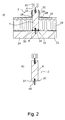
- Fig. 2 illustrates a schematic cross-sectional view of the attachment member 2 mounted in bore 26 shown in Fig. 1 c) .
- the attachment member 2 is almost identical to the attachment member 2 illustrated in Fig. 1 . The only difference is, that a recess 37 configured to receive and contain a flexible sealing member 32 is provided at the periphery at the lower portion of the connection member 4.
- Fig. 2 b illustrates a cross-sectional view of an attachment member 2 according to the invention. It can be seen that the recess 37 extends along the lower part of the cylindrical connection member 4 at the periphery of the lower circular contact surface 40.
- connection member 4 It is possible to seal the vapor barrier 22 against the connection member 4 without having a recess 37.
- a recess 37 that extends along the lower part of the cylindrical connection member 4, along the periphery of the lower circular contact surface 40, it is possible to provide a user-friendly attachment member 2 having a recess of a geometrical shape providing optimal sealing conditions (by having an optimum volume of sealing material).
- Fig. 3 a illustrates a schematic view of an attachment member 2 according to the invention.
- the attachment member 2 has a longitudinal axis X and comprises a connection member formed as a baluster 76.
- a lower attachment element 8 is provided at the bottom of the baluster 76.
- the baluster 76 is shaped as a tapered threaded metal rod 8 extending parallel to the longitudinal axis X of the attachment member 2.
- the tapered metal rod 8 is configured to be attached to a underlying construction element such as a layer of concrete or a wooden beam (rafter).
- a first clamping bracket 72 is fixed to the upper portion of the baluster 76 by means of an upper plate-shaped attachment element 6.
- a second clamping bracket 74 is fixed to the lower portion of the baluster 76.
- a plate member (e.g. a glass plate or a photovoltaic panel) 70 is held in place by means of the first clamping bracket 72 and the second clamping bracket 74. Sealing elements 78, 78' are provided between the clamping brackets 72, 74 and the plate member 70 in order to ensure a continuous and sustained attachment of the plate member 70.
- the plate 70 extends parallel to the longitudinal axis X of the attachment member 2.
- Fig. 3 b illustrates a schematic view of another attachment member 2 according to the invention.
- the attachment member 2 has a longitudinal axis X and a connection member formed as a baluster 76 corresponding to the one illustrated in Fig. 3 a) .
- a lower attachment element 8 is provided in the bottom end of the baluster 76.
- the lower attachment element 8 extends parallel to the longitudinal axis X of the attachment member 2.
- the lower attachment element 8 is formed as a tapered threaded rod 8 that is configured to be attached to an underlying construction element such as a concrete layer or a wooden element (e.g. a rafter).
- a first clamping bracket 72 is attached to the upper portion of the baluster 76 by means of an upper attachment element 6 shaped as a threaded rod (e.g. a threaded metal rod) extending parallel to the longitudinal axis of the attachment member 2.
- a threaded rod e.g. a threaded metal rod
- a second clamping bracket 74 is attached to the lower portion of the baluster 76.
- a plate member 70 extending parallel to longitudinal axis X of the attachment member 2 is fixed by means of the first clamping bracket 72 and the second clamping bracket 74.
- Sealing elements 78, 78' configured to provide a continuous and sustained attachment of the plate member 70 relative to the clamping brackets 72, 74 are provided between the clamping brackets 72, 74.
- Fig. 4 illustrates various schematic illustrations of two different attachment members 2 according to the invention.
- Fig. 4 a shows a side view of an attachment member 2 according to the invention.
- the attachment member 2 comprises a solid cylindrical connection member 4 provided with a planar upper contact surface 38 and a planar lower contact surface 40.
- a screw member 8 is attached into the solid cylindrical connection member 4 by moulding.
- the screw member 8 extends parallel to the longitudinal axis X of the attachment member 2.
- a mount 10 is provided in the opposite end of the connection member 4.
- the mount is attached by means of a nut 36 and a bolt 6 to the connection member 4.
- the mount 10 abuts the upper contact surface 38.
- the bolt 6 may be moulded into the connection member 4 or be attached to the connection member 4 by mechanical means.
- Fig. 4 b illustrates a perspective top view of the attachment member 2 shown in Fig. 4 a) . It can be seen from Fig. 4 b) that that the mount (or bracket) 10 is symmetrical, U-shaped and comprises a base plate abutting against the contact surface 38.
- bracket 10 is attached to a centrally arranged threaded rod (a bolt) 6 by means of a nut 36 that has been tightened in such a manner that the mount 10 is brought into mechanical contact with the contact surface 38.
- Fig. 4 c) shows a perspective view of the attachment member 2 illustrated in Fig. 4 a) and in Fig. 4 b) .
- Fig. 4 d shows another perspective view of the attachment member 2 illustrated in Fig. 4 a), Fig. 4 b) and Fig. 4 c) .
- Fig. 4 e illustrates a side view of an attachment member 2 according to the invention.
- the attachment member 2 comprises a cylindrical connection member 4 having a planar upper contact surface 38 and a planar lower contact surface 40.
- the connection member 4 comprises a conical surface 42 provided in the upper portion of the connection member 4.
- the attachment member 2 comprises a mount 10 that is attached to the connection member 4 in the same way as the attachment member 2 shown in and explained with reference to Fig. 4 a), Fig. 4 b), Fig. 4 c) and Fig. 4 d) .
- connection member 4 is significantly larger than both the length L 1 of the attachment element 8 and the total length L 2 of the mount 10 and that portion of the threaded rod 8 that extends beyond the connection member 4.
- Fig. 4 e illustrates a side view of another attachment member 2 according to the invention.
- the attachment member 2 comprises connection member 4 having an upper planar contact surface 38 and a lower planar contact surface 40.
- the upper contact surface 38 is angled (about 70 degrees) relative to the longitudinal axis X of the connection member 4, whereas the lower contact surface 40 extends perpendicular to the longitudinal axis X of the connection member 4.
- a lower attachment element shaped as a screw 8 is attached to the lower portion of the cylindrical connection member 4 by means of moulding.
- a mount 10 is attached to the upper contact surface 38.
- the mount 10 is configured to installation of mounting rails or other objects that are intended to be attached in such a manner that they are angled relative to the underlying construction element. This is in particular an advantage when mounting solar panels on a flat roof.
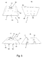
- Fig. 5 illustrates another attachment member 2 according to the invention.
- Fig. 5 a illustrates a perspective top view of an attachment member 2 according to the invention.
- the attachment member 2 comprises connection member 4 formed as a massive block having a centrally and symmetrically provided upper contact surface 38 surrounded by four inclined sides 44. Each of the inclined sides 44 extends between an edge 46 that extends perpendicular to a lower square contact surface 40 (see Fig. 5b ).
- the bores 48 extend perpendicular to both the upper contact surface 38 and the lower contact surface 40.
- the bores 48 are configured to receive screws 50 for attaching the block 4 to an underlying construction (e.g. a non-isolated roof).
- a mount (bracket) 10 for attachment of mounting rails for solar panels are provided in the block.
- the mount 10 is attached to the upper portion of the block 4.
- Fig. 5 c) illustrates a perspective top view of the attachment member 2 shown in Fig. 5 a) and Fig. 5 b) .
- Four screws 50 are provided in the four corner bores of the attachment member 2. These screws 50 are configured to attach the attachment member 2 to an underlying roof 52 (e.g. a non-isolated roof covered with roofing felt).
- a centrally arranged mount (bracket) 10 is attached to the central region of the block 4.
- the mount 10 is attached by means of a threaded rod that is attached to the block e.g. by a moulding process. It can be seen that the mount 10 is slightly raised above the upper contact surface 38 of the block.
- Fig. 5 d illustrates a perspective view of four attachment members 2 mounted on a roof 52 in a square configuration in such a manner that the mounts 10 can be used to mount solar panels (not shown).
- the attachment members 2 shown in Fig. 5 provide a firm and stable attachment to the underlying roof 52. On flat (extending parallel to horizontal) roofs these attachment members 2 can be used.
- the mounts 10 may be provided in different levels (vertical positions) in order to angle e.g. a solar panel relative to horizontal. This is an advantage in order to increase the power produced by the solar panel. Thus, the need for a rack or mounting frame can be eliminated.
- the four inclined sides 44 are provided in order to attach and seal the roofing felt on the top portion and side portions of the block 4, when the block has been mounted on an underlying construction element.
- FIG. 6 illustrates cross-sectional views of three different steps during installation of an attachment member 2 according to the invention.
- An exploded view of a disassembled attachment member 2 is shown in Fig. 6a) .
- the attachment member 2 comprises a massive cylindrical connection member 4.
- a first bore 54 and a second bore 56 are provided in the attachment member 2.
- the first bore 54 and the second bore 56 extend parallel to the longitudinal axis X of the connection member 4.
- An adhesive 34 is provided in the first bore 54 and in the second bore 56.
- the adhesive 34 is configures to fix a lower attachment element 8 and an upper attachment element 6 to the connection member 4.
- a mount 10 provided with apertures 12 is arranged next to the upper attachment element 6.
- Fig. 6 b) illustrates a cross-sectional view of the attachment member 2 shown in Fig. 6 a) .
- the lower attachment element 8 and the upper attachment element 6 are fixed in the bores 54, 56.
- Fig. 6 c illustrates the attachment member 2 shown in Fig. 6 a) and in Fig. 6b ).
- a mount 10 provided with apertures 12 is attached to the upper attachment element 6.
- the illustrated attachment member 2 is now ready for being used for installation of items (e.g. solar panels) on a roof (e.g. a roof like the one shown in Fig. 1 ).
- Fig. 7 illustrates cross-sectional views of three different steps during the construction of attachment member 2 according to the invention.
- Fig. 7 a illustrates attachment member 2 in a disassembled state.
- the attachment member 2 comprises a solid cylindrical connection element 4 provided with a through-going bore 60 extending parallel to the longitudinal axis X of the connection member 4.
- An upper recess 62 and lower recess 64 are provided in the connection member 4.
- a threaded rod 58 provided with a tapered distal end is arranged next to the connection member 4.
- a mount (bracket) 10 is provided slightly above and next to the upper portion of the connection member 4.
- the mount 10 is configured to be attached to the threaded rod 58.
- a flat nut 66 is provided in the lower recess.
- the nut 66 is screwed onto the threaded rod 58 that has been inserted into the through-going bore.
- a second flat nut 68 has been mounted (screwed onto) the threaded rod 58 in Fig. 7 c) .
- the second flat nut 68 is arranged within the upper recess and the threaded rod 58 extends through the two nuts 66, 68 and the through-going bore.
- the mount (bracket) 10 has been secured to the threaded rod 58. Accordingly, the attachment member 2 is ready for use.
- connection member 4 As an alternative to one threaded rod 58 it is possible to apply two through-going threaded rods being mechanically attached to the connection member 4. Hereby it is possible top adjust the distance L 2 between the connection member 4 and the mount 10 and the distance L 1 from the connection member 4 to the pointed end of the threaded rod 58 independently.
- the attachment member 2 may comprise a socket or brushing having an inner thread configured to receive a threaded rod 58.
- Fig. 8 a illustrates a schematic cross-sectional view of how the connection member 4 may be sealed against the underlying support (e.g. a not shown vapor barrier).
- the attachment member 2 comprises a cylindrical connection member 4.
- the attachment member 2 is provided with an upper attachment element 6 formed as a threaded rod 6, onto which a mount 10 for mounting a mounting frame (see Fig. 9 ) is mounted.
- the attachment member 2 is adapted to be screwed into an underlying construction element by means of a lower attachment element 8 formed as a screw 8.
- the attachment member 2 extends through an insulation material arranged below a support 90 (e.g. roofing felt).
- the connection member 4 is sealed up against the underlying vapour barrier (not shown) by blowing a sealing material through a plurality of pipes (e.g. rubber or silicone) 80, 80'.
- the pipes 80, 80' are mounted in through-going bores 82, 82' provided in the lower portion of the connection member 4.
- connection member 4 will flow into the gap between the connection member 4 and the vapour barrier when the sealing material is blown through the pipes 80, 80' and further through the bores 82, 82'.
- connection member 4 is sealed against the vapour barrier.
- the bores 82, 82' are sealed against the surroundings by filling the bores 82, 82' up with sealing material.
- Fig. 8 b illustrates a schematic view of an attachment member 2, comprising a cylindrical connection element 4.
- the connection element 4 is provided with an upper attachment element 6 shaped as a threaded rod 6.
- a mount 10 for mounting a mounting frame of the type illustrated in Fig. 9 is attached to the attachment element 6.
- the attachment member 2 is configured to be screwed into an underlying construction element by means of a lower attachment element 8 shaped as a screw 8.
- a bag 84 surrounds a portion of the screw 8.
- the bag 84 contains a sealing material.
- the sealing material will flow out of the bag 84 and be evenly distributed to the area between the connection element 4 and the underlying vapour barrier when the attachment member 2 is screwed into the underlying construction element (not shown) by means of a lower attachment element 8 shaped as a screw 8.
- an appropriate sealing can be provided between the connection element 4 and the underlying vapour barrier.
- a (small) moisture sensor (not shown) into the lower part of the connection member 4 in order to be informed in case of water regress.
- the sensor may be provided with a battery having a capacity to provide adequate service life of the sensor.
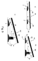
- Fig. 9 shows schematic views of different ways in which solar panels 86 can be mounted on a flat roof.
- Fig. 9 schematically illustrates different ways of mounting solar panels 86 on a flat roof.
- Fig. 9 a illustrates a solar panel 86 mounted on a first mounting frame 88 and a second mounting frame 88'.
- the mounting frames 88, 88' are fixed respectively to a first attachment element 6 and a second attachment element 6'.
- the first attachment element 6 and a second attachment element 6' are mounted respectively on a first connection member 4 and a second connection member 4'.
- the second mounting frame 88' is positioned in a slightly higher level on the second attachment element 6' than the first mounting frame 88. Accordingly, the solar panel 86 extends in an angle ⁇ relative to the support 90 (e.g. roofing felt).
- Fig. 9 b illustrates a solar panel 86' mounted on a first mounting frame 88 and a second mounting frame 88'.
- the mounting frames 88, 88' are fixed to a first attachment element 6 and a second attachment element 6', respectively.
- the first attachment member 6 is mounted on a first connection member 4, while the second attachment element 6' is secured to a second connection member 4'.
- the second connection member 4' has a different geometric shape and height than the first connection member 4. It can be seen that by using different connection members 4, 4' (having different heights) the solar panel 86' extends along a plane provided in an angle ⁇ relative to the support 90.
- Fig. 9 c illustrates a solar panel 86' mounted on a first mounting frame 88 and a second mounting frame 88', respectively.
- the mounting frames 88, 88' are mounted on a first attachment element 6 and a second attachment element 6'.
- the first attachment element 6 is mounted on a first connection member 4, while the second attachment element 6' is secured to a second connection member 4' being higher and having a different geometric shape than the first connection member 4.
- the connection members 4, 4' may be attached to the support 90 by gluing or by use of mechanical means.
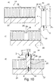
- Fig. 10 schematically shows illustrations similar to the one shown in Fig. 1 .
- the attachment member 2 is attached to an underlying construction element 24 in an insulated roof.
- the roofing felt 28 is mounted on top of the insulation 20 without any layer in between. The remaining elements are explained with reference to Fig. 1 . It can be seen that the isolated roof comprises an upper roofing felt layer 28 placed on top of the insulation 20.
- Fig. 11 illustrates attachment members 2 configured to be attached directly into a support or the substrate such as soil, sand, clay or the like.
- the attachment members 2 are configured to be mounted in outside directly into the soil.
- the attachment member 2 shown in Fig. 11 a) comprises an elongated cylindrical connecting member 4 and a lower screw member 8.
- connection element 4 and a lower screw member 8 are integrated into the one and same element made in a material that can withstand the cold, vibrations and temperature stresses that one would expect when the attachment member 2 is installed outside in the ground.
- attachment member 2 It may be advantageous to manufacture the attachment member 2 in a plastic material (e.g. recycled plastics).
- An upper attachment element 6 in the form of a threaded rod 6 is provided in the upper part of the connection member 4.
- a mount 10 is attached to the top of the connecting element 4.
- Two radially extending handles 92, 92' are provided in the upper portion of the connection member 4. These handles 92, 92' may be used when rotating the attachment member into the support (e.g. sand or soil). It may be advantageous to mount the attachment member 2 in a predrilled hole in the ground.
- Fig. 11 b illustrates an attachment member 2 almost similar to the one shown in Fig. 11 a) . The only difference is that the attachment member 2 shown in Fig. 11 b) contains no handles.
- Fig. 12 shows alternative attachment members 2 having the same outer geometry as the one shown in Fig. 5 .
- Fig. 12 a illustrates a perspective top view of the attachment member 2 that comprises a connection member 4, a bracket 10 provided with an upper contact surface 38, four edges 46 and four inclined sides 44.
- the spikes 96 of two bung members 94 are shown.
- Fig. 12 b illustrates s perspective bottom view of the attachment member 2 in which two bung members 94 each provided with a spike 96 are arranged below the attachment member 2. These bung members 94 are configured to be inserted into the bores 48.
- Fig. 12 d illustrates a perspective bottom view of an attachment member 2 in which four spikes 96 protrudes from the lower contact surface 40 of the attachment members 2.
- Fig. 12 c) shows a perspective top view of the attachment member 2 shown in Fig. 12 d) .
- the attachment member 2 shown in Fig. 12 comprise a bracket 10 provided with the upper contact surface 38, four edges 46 and four inclined sides 44. Moreover, the attachment members 2 are provided with six bores 48.
- the bung members 94 may be conical in order to achieve an easy way of attaching them to the connection member 4.
- the attachment member 2 may be glued to a roof. The spikes will prevent the attachment member 2 from skidding.
Landscapes
- Engineering & Computer Science (AREA)
- Physics & Mathematics (AREA)
- Life Sciences & Earth Sciences (AREA)
- Sustainable Development (AREA)
- Sustainable Energy (AREA)
- Thermal Sciences (AREA)
- Chemical & Material Sciences (AREA)
- Combustion & Propulsion (AREA)
- Mechanical Engineering (AREA)
- General Engineering & Computer Science (AREA)
- Roof Covering Using Slabs Or Stiff Sheets (AREA)
- Photovoltaic Devices (AREA)
Abstract
Description
- The present invention generally relates to an attachment member for attaching one or more objects to an underlying construction element. The present invention more particularly relates to an attachment member configured to secure solar panels e.g. solar photovoltaic panels or solar mounts to one or more underlying construction elements such as a rafter or a concrete deck.
- Mounting of items such as solar panels to a roof covered with roofing felt requires special mounts or brackets configured to receive the mounting rail onto which the solar panels have to be secured. During the mounting process it is of great importance that the areas in which the roofing felt is penetrated is sealed in order to prevent water ingress.
- Different types of mounts and brackets have been suggested for the purpose of being secured to an underlying roof by mechanical means such as screws. These mounts and brackets are, however, expensive and are not suitable for being used in all applications.
- Therefore, a low-cost alternative to existing types of mounting brackets is desirable.
- During installation of solar panels to an isolated roof, there is a particular need for attaching the mounting rails to construction elements provided below an insulating material located under the roofing felt. Such construction elements may be a rafter or a concrete layer or concrete deck. No commercially available mounting bracket can be used for the installation of solar panels on an insulated roof as just mentioned.
- Accordingly, it would be desirable to have brackets or mounts suitable for being used to install solar panels and other objects on an insulated roof. It is an object of the present invention to specify an attachment member that is cheaper to produce than the existing types of brackets and mounts for installation of solar panels and mounting rails. It is also an object of the present invention to provide an attachment member suitable for being secured to an isolated roof.
- The object of the present invention can be achieved by an attachment member as defined in claim 1. Preferred embodiments are defined in the dependent sub claims and explained in the following description and illustrated in the accompanying drawings.
- The attachment member according to the invention is an attachment member for attaching one or more objects such as mounting rails for solar panels to an underlying construction element such as a rafter or a concrete deck, where the attachment member comprises a massive or semi-massive connection member having a longitudinal axis and an upper end and a lower end, where: a) at least one lower attachment element configured to be mounted in the underlying construction element is attached to the connection member or b) or where means for mounting one or more means for attachment into the underlying construction element are provided in the connection member, where a mount or bracket configured for mounting objects such as a mounting rails for attachment of solar panels or a unit for attachment of a mount or a bracket for mounting of objects such as a mounting rails for attachment of solar panels are attached to the upper portion of the connection member, wherein the connection member is configured to transfer load from the mount, the bracket or the unit for attachment of the mount or bracket to the at least one lower attachment element, where the connection member comprises a lower connection surface extending basically perpendicular to the longitudinal axis of the connection member, where the lower connection surface is configured to bear against the underlying construction element and hereby provide a stabilising lower connection surface when the attachment member is mounted to the underlying construction element, where the at least one lower attachment element protrudes from the lower connection surface and extends along the longitudinal axis of the connection member.
- Hereby it is possible to provide an attachment member that is cheaper to produce than the existing types of brackets and mounts for installation of solar panels and mounting rails. Moreover it is possible to provide an attachment member suitable for being secured to an isolated roof.
- The attachment member may be used to mount mounting rails for attachment of solar panels to an underlying roof, including rafters, plywood, boards or concrete.
- The attachment member may be used to mount ventilation devices, rood arrangements in general including guiding rails and the like.
- It may be an advantage that the connection member is massive since it may reduce the production costs and make it easier to manufacture the attachment member. The attachment member may be moulded in plastic by means of e.g. injection moulding or extrusion or cutting.
- The lower attachment element may be made in metal e.g. stainless steel. It may be beneficial that the lower attachment element is shaped as a screw or another element suitable for being attached to wood or stoe or concrete. The lower attachment element may be any suitable type of screw including a lag screw, a twinfast screw, an anchor bolt, a self-drilling screw or any other suitable type of attachment element.
- It is possible to apply one or more attachment elements.
- Attachment of the attachment element to the connection member may be carried out by any suitable means e.g. moulding, gluing or mechanical attachment e.g. by screwing.
- It may be an advantage that the connection member is massive or almost massive.
- It is an advantage to have a connection member configured to transfer load from the mount, the bracket or the unit for attachment of the mount or bracket to the at least one lower attachment element, where the connection member comprises a lower connection surface extending basically perpendicular to the longitudinal axis of the connection member, where the lower connection surface is configured to bear against the underlying construction element and hereby provide a stabilising lower connection surface when the attachment member is mounted to the underlying construction element. Hereby it is possible to provide a reliable and torsionally rigid anchoring.
- When the at least one lower attachment element protrudes from the lower connection surface and extends along the longitudinal axis of the connection member it is possible to ensure a firm attachment of the attachment member.
- It may be an advantage that the connection member is a massive member made in plastic, where at least one lower attachment element shaped as a tapered rod member, preferably a threaded metal rod.
- Such attachment member provides a fast and easy mounting of the attachment member.
- It may be an advantage that the connection member comprises an upper planar connection surface extending basically perpendicular to the longitudinal axis of the connection member.
- It may be beneficial that the connection member comprises an upper planar contact surface angled between 45 and 90 grader relative to the longitudinal axis of the connection member. Hereby it is possible to angle the objects relative to horizontal.
- It may be beneficial that the connection member comprises an upper planar contact surface angled between 60 and 80 grader relative to the longitudinal axis of the connection member so that solar panels may be mounted 10-30 degrees relative to an underlying roof (e.g. a horizontal roof).
- It may be advantageous that the connection member comprises a cylindrical portion and comprises a planar circular upper contact surface and a planar lower contact surface. Such construction is cheap, easy to produce and strong.
- It may be an advantage that the connection member comprises a rectangular, preferably square cross section and comprises a planar and rectangular, preferably square upper contact surface and a planar rectangular, preferably square lower contact surface extending basically parallel to the upper contact surface, where a plurality of bores are provided in the connection member, through which bores the attachment member is configured to be attached to the underlying construction element. Such connection member is easy to seal when mounting it on roofing felt.
- It may be an advantage that the connection member comprises a rectangular, preferably square cross section and comprises a planar and rectangular, preferably square upper contact surface and a planar rectangular, preferably square lower contact surface extending basically parallel to the upper contact surface, where a plurality of through-going bores are provided in the connection member, through which through-going bores the attachment member is configured to be attached to the underlying construction element.
- It may be beneficial that a centrally arranged mount or bracket is attached to connection member, where the mount or bracket is attached to a threaded rod, which threaded rod is moulded or mechanically attached to the connection member. Such construction is simple and strong.
- It may be an advantage that a first bore is provided in the upper portion of the connection member and a lower bore is provided in the connection member, where the two bores extend basically parallel to the longitudinal axis of the connection member, where an upper attachment element is formed as a threaded rod is mounted in the first bore. Where the lower attachment element is formed as a threaded rod and is mounted in the second bore.
- It may be advantageous that a through-going bore is provided in the connection member and that a through-going rod member extends through the through-going bore and is attached to the connection member. Such construction is easy to produce, strong and reliable.
- It may be an advantage that the rod member is a threaded rod member. Hereby it is possible to provide a firm attachment.
- It may be beneficial that the attachment member is configured to upon rotation of the threaded rod member adjust the position of the mount or bracket relative to the connection member. Hereby adjustment may be provided.
- It may advantageous that the attachment member is configured to upon rotation of the threaded rod member adjust the distance from the connection member to the distal end of the lower attachment element being shaped as a threaded rod member.
- It may be an advantage that a recess configured to receive and contain a flexible sealing member is provided at the periphery at the lower portion of the connection member. Hereby it is possible to provide an appropriate and desirable sealing.
- It may beneficial that the attachment member is configured to be mounted directly into soil, sand or gravel.
- It may be an advantage that the connection member comprises a plurality of spikes protruding from the lower contact surface. Hereby it is possibly to glue the attachment member to a roof in an easier manner. The spikes will prevent the attachment member from skidding.
- It may be advantageous that the connection member is provided with a plurality of bores and a plurality of bung members configured to be attachably inserted into the bores, where the bung members comprises a spike protruding from the bung members. Hereby it is easy to attach the bung members in the bores and hereby provide the connection member with spikes.
- It may be an advantage that the bung members are conical and the bores are cylindrical. The bung members may be cylindrical and the bores may be conical.
- It is possible to provide a flexible glue or sealing under the lower contact surface and glue the attachment member to e.g. a roof. Spikes will prevent the attachment member from skidding.
- It may be an advantage that the glue or sealing is flexible after it has set hard.
- The invention will become more fully understood from the detailed description given herein below. The accompanying drawings are given by way of illustration only, and thus, they are not limitative of the present invention. In the accompanying drawings:
- Fig. 1
- shows a schematic view of an attachment member according to the invention and an underlying construction element of an isolated roof;
- Fig. 2
- shows a schematic view of an alternative attachment member according to the invention and an underlying construction element of an isolated roof;
- Fig. 3
- shows a schematic view of two attachment members according to the invention;
- Fig. 4
- shows different views of two attachment members according to the invention;
- Fig. 5
- shows schematic views of an attachment member according to the invention;
- Fig. 6
- shows a schematic cross-sectional view of an attachment member according to the invention;
- Fig. 7
- shows a schematic cross-sectional view of another attachment member according to the invention;
- Fig. 8
- shows a schematic view of how to seal the attachment member according to the invention to an underlying construction;
- Fig. 9
- shows a schematic view of how to install solar panels on a flat roof;
- Fig. 10
- shows a schematic view of an attachment member according to the invention and how it is attached to an underlying construction element in an isolated roof, where the roofing felt is provided on the top of the insolation without a layer between the insolation and the roofing felt;
- Fig. 11
- shows schematic views of two attachment members according to the invention and
- Fig. 12
- schematic views of an attachment member according to the invention.
- Referring now in detail to the drawings for the purpose of illustrating preferred embodiments of the present invention, a schematic view of an attachment member according to the invention and an underlying construction element of an isolated roof are illustrated in
Fig. 1 . - The
roof 14 comprises an outer layer provided with roofing felt 28 attached to an underlying plywood plate 18 (or alternatively boards). An insolation layer 20 (e.g. mineral wool) is arranged below theplywood plate 18. Theinsolation layer 20 is provided above anunderlying construction element 24. Avapour barrier 22 is arranged between theinsolation 20 and theunderlying construction element 24. Theunderlying construction element 24 may be a rafter, a concrete layer or concrete deck. -
Fig. 1 b) illustrates a side view of anattachment member 2 according to the invention. Theattachment member 2 comprises an at least partly massivecylindrical connection member 4 comprising an upper planarcircular contact surface 38 and a lower planarcircular contact surface 40. - A
lower attachment element 8 protruding from thelower contact surface 40 is attached to theconnection member 4. Thelower attachment element 8 extends along the longitudinal axis X of theconnection member 4. - The
lower attachment element 8 is formed as a tapered metal rod that may be provided with an outer thread. - An
upper attachment element 6 that extends along the longitudinal axis X of theconnection member 4 and protrudes from theupper contact surface 38 is attached to theconnection member 4. Theupper attachment element 6 is shaped as a threaded metal rod having a distal end to which amount 10 is attached.Apertures 12 for attachment of e.g. a mounting rail for installation of a solar panel are provided in themount 10. - The length L3 of the
connection member 4 is significantly larger than the length L1 of thelower attachment element 8 and the total length L2 of themount 10 and the portion of the threadedrod 6 that extend beyond and protrudes from theconnection member 4. - It may be an advantage to produce the
connection member 4 in a plastic material, preferably, recycled plastic, including polyethylene that may be fiber-reinforced or modified in another way. -
Fig. 1 c) shows a cross-sectional view of a roof provided with acylindrical bore 26 for mounting of theattachment member 2 shown inFig. 1b ). - It should be noted that roofing felt 28 extends into the
bore 26. This loose roofing felt 28 is applied during the following sealing procedure of the mounted attachment member 2 (seeFig. 1 d) ). Thevapor barrier 22 is unbroken inFig. 1 c) and it may be an advantage to attempt to maintain as much of thevapor barrier 22 as possible in order to ensure the optimum sealing of thebore 26. - In
Fig. 1 d) showing a schematic cross-sectional view of theattachment member 2 mounted in thebore 26 illustrated inFig. 1c ). Thelower attachment element 8 is fixed in theunderlying construction element 24. This attachment may be carried out by applying a pre-drilled bore (not shown) provided in theunderlying construction element 24. - It can be seen from
Fig. 1 d) that the attachment member provides a stable construction due to the fact that since thelower contact surface 40 rests on theunderlying construction element 24. Moreover, it can be seen that the taperedmetal rod 8 is attached to theconnection member 4 by means of an adhesive 34. The adhesive 34 may advantageously be an anchoring material e.g. an anchoring material for chemical anchors installable in a drilled bore e.g. in a building material like stone or similar material such as concrete and brick. - The
vapor barrier 22 is partially compressed by theattachment member 2 attached on the top of it. As previously mentioned, it may be advantageously to maintain thevapor barrier 22 as intact as possible. - A T-shaped
collar 30 is provided on top of theplywood plate 18. Theplywood plate 18 abuts against theplywood plate 18 and encloses the part of theconnection member 4 that required to be sealed against ingress of water (coming from above). - The loose pieces of roofing felt 28 shown in
Fig. 1c ) are configured to be arranged on the top of the lower portion of the T-shapedcollar 30. When the loose pieces of roofing felt 28 are arranged on the top of the lower portion of the T-shapedcollar 30 the loose pieces of roofing felt 28 are sealingly attached to the lower portion of the T-shapedcollar 30 by heating the overlapping roofing felt 28. - The upper portion of the
connection member 4 is sealed against the T-shapedcollar 30 by means of aflexible sealing material 32, e.g. a heat-shrinkable tubing (heat-shrink tubing). Theflexible sealing material 32 is provided on the top portion of theconnection member 4 in such a manner that it at the same time overlaps the upper portion of the T-shapedcollar 30. A heat-shrinkable tubing may be made of nylon, polyolefin, a thermoplastic material such as polyolefin, fluoropolymer (e.g. FEP, PTFE or Kynar), PVC, neoprene, silicone elastomer or Viton which shrinks only radially when heated. - As an alternative to a heat-shrinkable tubing, the sealing may be provided by applying a T-shaped
plastic collar 30. The T-shapedplastic collar 30 is during heating sealed against theconnection member 4. - It is also possible to apply mechanical sealing means comprising a clamp and one or more rubber elements that upon the radially oriented forces from the clamp, seals the
collar 30 against theconnection member 4. - In
Fig. 1 d) it can moreover be seen that theupper attachment element 6 is attached to theconnection member 4 by means of an adhesive 34. -
Fig. 2 illustrates a schematic cross-sectional view of theattachment member 2 mounted inbore 26 shown inFig. 1 c) . Theattachment member 2 is almost identical to theattachment member 2 illustrated inFig. 1 . The only difference is, that arecess 37 configured to receive and contain aflexible sealing member 32 is provided at the periphery at the lower portion of theconnection member 4. - In
Fig. 2 a) it can be seen that the sealingmember 32 seals thevapor barrier 22 against theconnection member 4. -
Fig. 2 b) illustrates a cross-sectional view of anattachment member 2 according to the invention. It can be seen that therecess 37 extends along the lower part of thecylindrical connection member 4 at the periphery of the lowercircular contact surface 40. - It is possible to seal the
vapor barrier 22 against theconnection member 4 without having arecess 37. However, by providing arecess 37 that extends along the lower part of thecylindrical connection member 4, along the periphery of the lowercircular contact surface 40, it is possible to provide a user-friendly attachment member 2 having a recess of a geometrical shape providing optimal sealing conditions (by having an optimum volume of sealing material). -
Fig. 3 a) illustrates a schematic view of anattachment member 2 according to the invention. Theattachment member 2 has a longitudinal axis X and comprises a connection member formed as abaluster 76. - A
lower attachment element 8 is provided at the bottom of thebaluster 76. Thebaluster 76 is shaped as a tapered threadedmetal rod 8 extending parallel to the longitudinal axis X of theattachment member 2. The taperedmetal rod 8 is configured to be attached to a underlying construction element such as a layer of concrete or a wooden beam (rafter). - A
first clamping bracket 72 is fixed to the upper portion of thebaluster 76 by means of an upper plate-shapedattachment element 6. - A
second clamping bracket 74 is fixed to the lower portion of thebaluster 76. - A plate member (e.g. a glass plate or a photovoltaic panel) 70 is held in place by means of the
first clamping bracket 72 and thesecond clamping bracket 74.Sealing elements 78, 78' are provided between the clampingbrackets plate member 70 in order to ensure a continuous and sustained attachment of theplate member 70. Theplate 70 extends parallel to the longitudinal axis X of theattachment member 2. -
Fig. 3 b) illustrates a schematic view of anotherattachment member 2 according to the invention. Theattachment member 2 has a longitudinal axis X and a connection member formed as abaluster 76 corresponding to the one illustrated inFig. 3 a) . - A
lower attachment element 8 is provided in the bottom end of thebaluster 76. Thelower attachment element 8 extends parallel to the longitudinal axis X of theattachment member 2. Thelower attachment element 8 is formed as a tapered threadedrod 8 that is configured to be attached to an underlying construction element such as a concrete layer or a wooden element (e.g. a rafter). - A
first clamping bracket 72 is attached to the upper portion of thebaluster 76 by means of anupper attachment element 6 shaped as a threaded rod (e.g. a threaded metal rod) extending parallel to the longitudinal axis of theattachment member 2. - A
second clamping bracket 74 is attached to the lower portion of thebaluster 76. Aplate member 70 extending parallel to longitudinal axis X of theattachment member 2 is fixed by means of thefirst clamping bracket 72 and thesecond clamping bracket 74. -
Sealing elements 78, 78' configured to provide a continuous and sustained attachment of theplate member 70 relative to the clampingbrackets brackets -
Fig. 4 illustrates various schematic illustrations of twodifferent attachment members 2 according to the invention. -
Fig. 4 a) shows a side view of anattachment member 2 according to the invention. Theattachment member 2 comprises a solidcylindrical connection member 4 provided with a planarupper contact surface 38 and a planarlower contact surface 40. - A
screw member 8 is attached into the solidcylindrical connection member 4 by moulding. Thescrew member 8 extends parallel to the longitudinal axis X of theattachment member 2. - A
mount 10 is provided in the opposite end of theconnection member 4. The mount is attached by means of anut 36 and abolt 6 to theconnection member 4. Themount 10 abuts theupper contact surface 38. Thebolt 6 may be moulded into theconnection member 4 or be attached to theconnection member 4 by mechanical means. -
Fig. 4 b) illustrates a perspective top view of theattachment member 2 shown inFig. 4 a) . It can be seen fromFig. 4 b) that that the mount (or bracket) 10 is symmetrical, U-shaped and comprises a base plate abutting against thecontact surface 38. - Two side walls extend in parallel and protrude from the base plate that is provided with
apertures 12. Theseapertures 12 may be used during attachment of mounting rails for solar installation. It can be seen that thebracket 10 is attached to a centrally arranged threaded rod (a bolt) 6 by means of anut 36 that has been tightened in such a manner that themount 10 is brought into mechanical contact with thecontact surface 38. -
Fig. 4 c) shows a perspective view of theattachment member 2 illustrated inFig. 4 a) and inFig. 4 b) . -
Fig. 4 d) shows another perspective view of theattachment member 2 illustrated inFig. 4 a), Fig. 4 b) and Fig. 4 c) . -
Fig. 4 e) illustrates a side view of anattachment member 2 according to the invention. Theattachment member 2 comprises acylindrical connection member 4 having a planarupper contact surface 38 and a planarlower contact surface 40. Theconnection member 4 comprises aconical surface 42 provided in the upper portion of theconnection member 4. Theattachment member 2 comprises amount 10 that is attached to theconnection member 4 in the same way as theattachment member 2 shown in and explained with reference toFig. 4 a), Fig. 4 b), Fig. 4 c) and Fig. 4 d) . - It can be seen that the length L3 of the
connection member 4 is significantly larger than both the length L1 of theattachment element 8 and the total length L2 of themount 10 and that portion of the threadedrod 8 that extends beyond theconnection member 4. -
Fig. 4 e) illustrates a side view of anotherattachment member 2 according to the invention. Theattachment member 2 comprisesconnection member 4 having an upperplanar contact surface 38 and a lowerplanar contact surface 40. Theupper contact surface 38 is angled (about 70 degrees) relative to the longitudinal axis X of theconnection member 4, whereas thelower contact surface 40 extends perpendicular to the longitudinal axis X of theconnection member 4. - A lower attachment element shaped as a
screw 8 is attached to the lower portion of thecylindrical connection member 4 by means of moulding. Amount 10 is attached to theupper contact surface 38. Themount 10 is configured to installation of mounting rails or other objects that are intended to be attached in such a manner that they are angled relative to the underlying construction element. This is in particular an advantage when mounting solar panels on a flat roof. -
Fig. 5 illustrates anotherattachment member 2 according to the invention.Fig. 5 a) illustrates a perspective top view of anattachment member 2 according to the invention. Theattachment member 2 comprisesconnection member 4 formed as a massive block having a centrally and symmetrically providedupper contact surface 38 surrounded by fourinclined sides 44. Each of theinclined sides 44 extends between anedge 46 that extends perpendicular to a lower square contact surface 40 (seeFig. 5b ). - Six through-going
bores 48 are provided in themassive block 4. Thebores 48 extend perpendicular to both theupper contact surface 38 and thelower contact surface 40. Thebores 48 are configured to receivescrews 50 for attaching theblock 4 to an underlying construction (e.g. a non-isolated roof). A mount (bracket) 10 for attachment of mounting rails for solar panels are provided in the block. Themount 10 is attached to the upper portion of theblock 4. -
Fig. 5 c) illustrates a perspective top view of theattachment member 2 shown inFig. 5 a) and Fig. 5 b) . Fourscrews 50 are provided in the four corner bores of theattachment member 2. Thesescrews 50 are configured to attach theattachment member 2 to an underlying roof 52 (e.g. a non-isolated roof covered with roofing felt). - A centrally arranged mount (bracket) 10 is attached to the central region of the
block 4. Themount 10 is attached by means of a threaded rod that is attached to the block e.g. by a moulding process. It can be seen that themount 10 is slightly raised above theupper contact surface 38 of the block. -
Fig. 5 d) illustrates a perspective view of fourattachment members 2 mounted on aroof 52 in a square configuration in such a manner that themounts 10 can be used to mount solar panels (not shown). - The
attachment members 2 shown inFig. 5 provide a firm and stable attachment to theunderlying roof 52. On flat (extending parallel to horizontal) roofs theseattachment members 2 can be used. Themounts 10 may be provided in different levels (vertical positions) in order to angle e.g. a solar panel relative to horizontal. This is an advantage in order to increase the power produced by the solar panel. Thus, the need for a rack or mounting frame can be eliminated. - The four
inclined sides 44 are provided in order to attach and seal the roofing felt on the top portion and side portions of theblock 4, when the block has been mounted on an underlying construction element. - It may be an advantage to countersink the bores and cover them with a cover member such as bungs sealingly attached to the bores.
-
Fig. 6 illustrates cross-sectional views of three different steps during installation of anattachment member 2 according to the invention. An exploded view of a disassembledattachment member 2 is shown inFig. 6a) . Theattachment member 2 comprises a massivecylindrical connection member 4. Afirst bore 54 and asecond bore 56 are provided in theattachment member 2. Thefirst bore 54 and thesecond bore 56 extend parallel to the longitudinal axis X of theconnection member 4. - An adhesive 34 is provided in the
first bore 54 and in thesecond bore 56. The adhesive 34 is configures to fix alower attachment element 8 and anupper attachment element 6 to theconnection member 4. - A
mount 10 provided withapertures 12 is arranged next to theupper attachment element 6. -
Fig. 6 b) illustrates a cross-sectional view of theattachment member 2 shown inFig. 6 a) . Thelower attachment element 8 and theupper attachment element 6 are fixed in thebores -
Fig. 6 c) illustrates theattachment member 2 shown inFig. 6 a) and inFig. 6b ). Amount 10 provided withapertures 12 is attached to theupper attachment element 6. Now, the illustratedattachment member 2 is now ready for being used for installation of items (e.g. solar panels) on a roof (e.g. a roof like the one shown inFig. 1 ). -
Fig. 7 illustrates cross-sectional views of three different steps during the construction ofattachment member 2 according to the invention. -
Fig. 7 a) illustratesattachment member 2 in a disassembled state. Theattachment member 2 comprises a solidcylindrical connection element 4 provided with a through-goingbore 60 extending parallel to the longitudinal axis X of theconnection member 4. Anupper recess 62 andlower recess 64 are provided in theconnection member 4. A threadedrod 58 provided with a tapered distal end is arranged next to theconnection member 4. - A mount (bracket) 10 is provided slightly above and next to the upper portion of the
connection member 4. Themount 10 is configured to be attached to the threadedrod 58. - In
Fig. 7 b) aflat nut 66 is provided in the lower recess. Thenut 66 is screwed onto the threadedrod 58 that has been inserted into the through-going bore. - A second
flat nut 68 has been mounted (screwed onto) the threadedrod 58 inFig. 7 c) . The secondflat nut 68 is arranged within the upper recess and the threadedrod 58 extends through the twonuts rod 58. Accordingly, theattachment member 2 is ready for use. - By rotating the threaded
rod 58 the distance L2 from theconnection member 4 to themount 10 and/or the distance L1 from theconnection member 4 to the pointed end of the threadedrod 58 may be adjusted. This is an advantage. - As an alternative to one threaded
rod 58 it is possible to apply two through-going threaded rods being mechanically attached to theconnection member 4. Hereby it is possible top adjust the distance L2 between theconnection member 4 and themount 10 and the distance L1 from theconnection member 4 to the pointed end of the threadedrod 58 independently. - As an alternative to a threaded
rod 58, theattachment member 2 may comprise a socket or brushing having an inner thread configured to receive a threadedrod 58. -
Fig. 8 a) illustrates a schematic cross-sectional view of how theconnection member 4 may be sealed against the underlying support (e.g. a not shown vapor barrier). Theattachment member 2 comprises acylindrical connection member 4. - The
attachment member 2 is provided with anupper attachment element 6 formed as a threadedrod 6, onto which amount 10 for mounting a mounting frame (seeFig. 9 ) is mounted. Theattachment member 2 is adapted to be screwed into an underlying construction element by means of alower attachment element 8 formed as ascrew 8. - The
attachment member 2 extends through an insulation material arranged below a support 90 (e.g. roofing felt). Theconnection member 4 is sealed up against the underlying vapour barrier (not shown) by blowing a sealing material through a plurality of pipes (e.g. rubber or silicone) 80, 80'. Thepipes 80, 80' are mounted in through-goingbores 82, 82' provided in the lower portion of theconnection member 4. - The sealing material will flow into the gap between the
connection member 4 and the vapour barrier when the sealing material is blown through thepipes 80, 80' and further through thebores 82, 82'. Hereby theconnection member 4 is sealed against the vapour barrier. Thebores 82, 82' are sealed against the surroundings by filling thebores 82, 82' up with sealing material. -
Fig. 8 b) illustrates a schematic view of anattachment member 2, comprising acylindrical connection element 4. Theconnection element 4 is provided with anupper attachment element 6 shaped as a threadedrod 6. Amount 10 for mounting a mounting frame of the type illustrated inFig. 9 is attached to theattachment element 6. - The
attachment member 2 is configured to be screwed into an underlying construction element by means of alower attachment element 8 shaped as ascrew 8. - A
bag 84 surrounds a portion of thescrew 8. Thebag 84 contains a sealing material. The sealing material will flow out of thebag 84 and be evenly distributed to the area between theconnection element 4 and the underlying vapour barrier when theattachment member 2 is screwed into the underlying construction element (not shown) by means of alower attachment element 8 shaped as ascrew 8. Hereby an appropriate sealing can be provided between theconnection element 4 and the underlying vapour barrier. - It is possible to arrange a (small) moisture sensor (not shown) into the lower part of the
connection member 4 in order to be informed in case of water regress. The sensor may be provided with a battery having a capacity to provide adequate service life of the sensor.Fig. 9 shows schematic views of different ways in whichsolar panels 86 can be mounted on a flat roof. -
Fig. 9 schematically illustrates different ways of mountingsolar panels 86 on a flat roof.Fig. 9 a) illustrates asolar panel 86 mounted on a first mountingframe 88 and a second mounting frame 88'. The mounting frames 88, 88' are fixed respectively to afirst attachment element 6 and a second attachment element 6'. Thefirst attachment element 6 and a second attachment element 6' are mounted respectively on afirst connection member 4 and a second connection member 4'. The second mounting frame 88' is positioned in a slightly higher level on the second attachment element 6' than the first mountingframe 88. Accordingly, thesolar panel 86 extends in an angle α relative to the support 90 (e.g. roofing felt). -
Fig. 9 b) illustrates a solar panel 86' mounted on a first mountingframe 88 and a second mounting frame 88'. The mounting frames 88, 88' are fixed to afirst attachment element 6 and a second attachment element 6', respectively. - The
first attachment member 6 is mounted on afirst connection member 4, while the second attachment element 6' is secured to a second connection member 4'. The second connection member 4' has a different geometric shape and height than thefirst connection member 4. It can be seen that by usingdifferent connection members 4, 4' (having different heights) the solar panel 86' extends along a plane provided in an angle β relative to thesupport 90. -
Fig. 9 c) illustrates a solar panel 86' mounted on a first mountingframe 88 and a second mounting frame 88', respectively. The mounting frames 88, 88' are mounted on afirst attachment element 6 and a second attachment element 6'. Thefirst attachment element 6 is mounted on afirst connection member 4, while the second attachment element 6' is secured to a second connection member 4' being higher and having a different geometric shape than thefirst connection member 4. Thus the solar panel 86' extends along a plane provided in an angle θ relative to thesupport 90. Theconnection members 4, 4' may be attached to thesupport 90 by gluing or by use of mechanical means. -
Fig. 10 schematically shows illustrations similar to the one shown inFig. 1 . Theattachment member 2, however, is attached to anunderlying construction element 24 in an insulated roof. The roofing felt 28 is mounted on top of theinsulation 20 without any layer in between. The remaining elements are explained with reference toFig. 1 . It can be seen that the isolated roof comprises an upper roofing feltlayer 28 placed on top of theinsulation 20. -
Fig. 11 illustratesattachment members 2 configured to be attached directly into a support or the substrate such as soil, sand, clay or the like. Theattachment members 2 are configured to be mounted in outside directly into the soil. - The
attachment member 2 shown inFig. 11 a) comprises an elongatedcylindrical connecting member 4 and alower screw member 8. - The
connection element 4 and alower screw member 8 are integrated into the one and same element made in a material that can withstand the cold, vibrations and temperature stresses that one would expect when theattachment member 2 is installed outside in the ground. - It may be advantageous to manufacture the
attachment member 2 in a plastic material (e.g. recycled plastics). Anupper attachment element 6 in the form of a threadedrod 6 is provided in the upper part of theconnection member 4. - A
mount 10 is attached to the top of the connectingelement 4. - Two radially extending
handles 92, 92' are provided in the upper portion of theconnection member 4. These handles 92, 92' may be used when rotating the attachment member into the support (e.g. sand or soil). It may be advantageous to mount theattachment member 2 in a predrilled hole in the ground. -
Fig. 11 b) illustrates anattachment member 2 almost similar to the one shown inFig. 11 a) . The only difference is that theattachment member 2 shown inFig. 11 b) contains no handles. -
Fig. 12 showsalternative attachment members 2 having the same outer geometry as the one shown inFig. 5 . -
Fig. 12 a) illustrates a perspective top view of theattachment member 2 that comprises aconnection member 4, abracket 10 provided with anupper contact surface 38, fouredges 46 and fourinclined sides 44. Thespikes 96 of twobung members 94 are shown. -
Fig. 12 b) illustrates s perspective bottom view of theattachment member 2 in which twobung members 94 each provided with aspike 96 are arranged below theattachment member 2. Thesebung members 94 are configured to be inserted into thebores 48. -
Fig. 12 d) illustrates a perspective bottom view of anattachment member 2 in which fourspikes 96 protrudes from thelower contact surface 40 of theattachment members 2. -
Fig. 12 c) shows a perspective top view of theattachment member 2 shown inFig. 12 d) . - The
attachment member 2 shown inFig. 12 comprise abracket 10 provided with theupper contact surface 38, fouredges 46 and fourinclined sides 44. Moreover, theattachment members 2 are provided with six bores 48. Thebung members 94 may be conical in order to achieve an easy way of attaching them to theconnection member 4. Theattachment member 2 may be glued to a roof. The spikes will prevent theattachment member 2 from skidding. -
- 2
- Attachment member
- 4, 4'
- Connection member
- 6, 6'
- Upper attachment element
- 8
- Lower attachment element
- 10
- Mount
- 12
- Aperture
- 14
- Roof
- 16
- Roofing felt
- 18
- Underlying member (e.g. a plywood plate or boards)
- 20
- Insulation
- 22
- Vapour barrier
- 24
- Construction element (e.g. a rafter)
- 26
- Bore
- 28
- Roofing felt
- 30
- Collar
- 32
- Sealing member
- 34
- Adhesive (e.g. an anchoring material)
- 35
- Sealing member
- 36
- Nut
- 38
- Uppe contact surface
- 40
- Lower contact surface
- 42
- Conical surface
- 44
- Inclined side
- 46
- Edge
- 48
- Bore
- 50
- Screw
- 52
- Roof
- 54, 56
- Bore
- 58
- Through-going rod member/threaded rod
- 60
- Through-going bore
- 62, 64
- Recess
- 66, 68
- Nut
- 70
- Plate member
- 72
- Clamping bracket
- 74
- Clamping bracket
- 76
- Baluster
- 78
- Sealing element
- X
- Longitudinal axis
- L1, L2, L3
- Length/distance
- 80
- Pipe member or hose member
- 82, 82'
- Through-going bore
- 84
- Bag
- 86, 86'
- Solar panel
- 88, 88'
- Mounting frame
- 90
- Support
- α, β, θ
- Angle
- 92, 92'
- Handle
- 94
- Bung member
- 96
- Spike
Claims (15)
- An attachment member (2) for attaching one or more objects such as mounting rails for solar panels (86) to an underlying construction element (24) such as a rafter or a concrete deck, where the attachment member (2) comprises a massive or semi-massive connection member (4) having a longitudinal axis (X) and an upper end and a lower end, where:a) at least one lower attachment element (8) configured to be mounted in the underlying construction element (24) is attached to the connection member (4) orb) or where means (48) for mounting one or more means for attachment (50) into the underlying construction element (24, 52) are provided in the connection member (4),
where a mount (10) or bracket (10) configured for mounting objects such as a mounting rails for attachment of solar panels or a unit (6) for attachment of a mount (10) or a bracket (10) for mounting of objects such as a mounting rails for attachment of solar panels are attached to the upper portion of the connection member (4), characterised in that the connection member (4) is configured to transfer load from the mount (10), the bracket (10) or the unit (6) for attachment of the mount (10) or bracket (10) to the at least one lower attachment element (8), where the connection member (4) comprises a lower connection surface (40) extending basically perpendicular to the longitudinal axis (X) of the connection member (4), where the lower connection surface (40) is configured to bear against the underlying construction element (24) and hereby provide a stabilising lower connection surface (40) when the attachment member (2) is mounted to the underlying construction element (24), where the at least one lower attachment element (8) protrudes from the lower connection surface (40) and extends along the longitudinal axis (X) of the connection member (4). - An attachment member (2) according to claim 1, characterised in that the connection member (4) is a massive member (4) made in plastic, where at least one lower attachment element (8) shaped as a tapered rod member, preferably a threaded metal rod.
- An attachment member (2) according to claim 1 or claim 2, characterised in that the connection member (4) comprises an upper planar connection surface (38) extending basically perpendicular to the longitudinal axis (X) of the connection member (4).
- An attachment member (2) according to claim 1 or claim 2, characterised in that the connection member (4) comprises an upper planar contact surface (38) angled between 45 and 90 grader relative to the longitudinal axis (X) of the connection member (4).
- An attachment member (2) according to one of the preceding claims, characterised in that the connection member (4) comprises a cylindrical portion (4) and comprises a planar circular upper contact surface (38) and a planar lower contact surface (40).
- An attachment member (2) according to one of the preceding claims 1-5, characterised in that the connection member (4) comprises a rectangular, preferably square cross section and comprises a planar and rectangular, preferably square upper contact surface (38) and a planar rectangular, preferably square lower contact surface (40) extending basically parallel to the upper contact surface (38), where a plurality of bores (48) are provided in the connection member (4), through which bores (48) the attachment member (2) is configured to be attached to the underlying construction element (24, 52).
- An attachment member (2) according to one of the preceding claims 1-5, characterised in that the connection member (4) comprises a rectangular, preferably square cross section and comprises a planar and rectangular, preferably square upper contact surface (38) and a planar rectangular, preferably square lower contact surface (40) extending basically parallel to the upper contact surface (38), where a plurality of through-going bores (48) are provided in the connection member (4), through which through-going bores (48) the attachment member (2) is configured to be attached to the underlying construction element (24, 52).
- An attachment member (2) according to claim 6 or claim 7, characterised in that a centrally arranged mount (10) or bracket (10) is attached to connection member (4), where the mount (10) or bracket (10) is attached to a threaded rod (58), which threaded rod (58) is moulded or mechanically attached to the connection member (4).
- An attachment member (2) according to one of the claims 6-8, characterised in that a first bore (54) is provided in the upper portion of the connection member (4) and a lower bore (56) is provided in the connection member (4), where the two bores (54, 56) extend basically parallel to the longitudinal axis (X) of the connection member (4), where an upper attachment element (6) is formed as a threaded rod (6) is mounted in the first bore (54). Where the lower attachment element (8) is formed as a threaded rod (8) and is mounted in the second bore (56)
- An attachment member (2) according to one of the preceding claims, characterised in that a through-going bore (60) is provided in the connection member (4) and that a through-going rod member (58) extends through the through-going bore (60) and is attached to the connection member (4).
- An attachment member (2) according to claim 10, characterised in that the rod member (58) is a threaded rod member (58).
- An attachment member (2) according to claim 11, characterised in that the attachment member (2) is configured to upon rotation of the threaded rod member (58) adjust the position of the mount (10) or bracket (10) relative to the connection member (4).
- An attachment member (2) according to claim 11 or claim 12, characterised in that the attachment member (2) is configured to upon rotation of the threaded rod member (58) adjust the distance from the connection member (4) to the distal end of the lower attachment element (8) being shaped as a threaded rod member (58).
- An attachment member (2) according to one of the preceding claims, characterised in that the connection member (4) comprises a plurality of spikes (96) protruding from the lower contact surface (40).
- An attachment member (2) according to claim 14, characterised in that the connection member (4) is provided with a plurality of bores (48) and a plurality of bung members (94) configured to be attachably inserted into the bores (48), where the bung members (94) comprises a spike (96) protruding from the bung members (94).
Applications Claiming Priority (1)
| Application Number | Priority Date | Filing Date | Title |
|---|---|---|---|
| DK201300381A DK178166B1 (en) | 2013-06-20 | 2013-06-20 | Fastener for mounting objects on an underlying structural element |
Publications (2)
| Publication Number | Publication Date |
|---|---|
| EP2816298A1 true EP2816298A1 (en) | 2014-12-24 |
| EP2816298B1 EP2816298B1 (en) | 2019-07-31 |
Family
ID=50980106
Family Applications (1)
| Application Number | Title | Priority Date | Filing Date |
|---|---|---|---|
| EP14002130.4A Active EP2816298B1 (en) | 2013-06-20 | 2014-06-20 | Attachment member for attaching objects to an underlying construction element |
Country Status (2)
| Country | Link |
|---|---|
| EP (1) | EP2816298B1 (en) |
| DK (1) | DK178166B1 (en) |
Citations (4)
| Publication number | Priority date | Publication date | Assignee | Title |
|---|---|---|---|---|
| US20080087275A1 (en) * | 2006-10-16 | 2008-04-17 | Rovshan Sade | Solar Installation System |
| EP2267793A1 (en) * | 2009-06-22 | 2010-12-29 | L & T Partners | Attachment assembly for a panel |
| WO2012061796A1 (en) * | 2010-11-05 | 2012-05-10 | Sponseller Gregory W | Photovoltaic panel racking assembly for use in connection with roof installation of panels |
| GB2487568A (en) * | 2011-01-27 | 2012-08-01 | Carl Raymond Reynolds | Roof tile with attachment for fixing additional accessories to the roof |
Family Cites Families (9)
| Publication number | Priority date | Publication date | Assignee | Title |
|---|---|---|---|---|
| US20070144105A1 (en) * | 2005-12-22 | 2007-06-28 | Blanchard Edward C | Mounting bracket for roof-top structures |
| US7857269B2 (en) * | 2006-11-29 | 2010-12-28 | Pvt Solar, Inc. | Mounting assembly for arrays and other surface-mounted equipment |
| US7861485B1 (en) * | 2007-06-26 | 2011-01-04 | Wentworth Stuart H | Method for installing a stanchion on a tile roof and system therefor |
| DE102007053373A1 (en) * | 2007-11-09 | 2009-05-14 | Greenonetec Solarindustrie Gmbh | Mounting bracket for solar collector, has U-shaped section for force-fit mounting on corresponding rail and another section for force-fit fixing of collector |
| US8251326B2 (en) * | 2008-05-22 | 2012-08-28 | Mainstream Energy Corporation | Camming clamp for roof seam |
| US8209914B2 (en) * | 2010-01-25 | 2012-07-03 | Vermont Slate & Copper Services, Inc. | Roofing grommet forming a seal between a roof-mounted structure and a roof |
| CA2755097A1 (en) * | 2010-10-14 | 2012-04-14 | D Three Enterprises, Llc | Flashing assembly |
| DE102011008591A1 (en) * | 2011-01-17 | 2012-08-30 | Christoph Gruß | Vertically adjustable, motion accommodating and partially reversible universal mounting bracket for penetration-free assembly of e.g. photovoltaic plants, on roof of e.g. building, has base plate mounted using adhesive |
| DE102012005739A1 (en) * | 2012-03-23 | 2013-09-26 | Illinois Tool Works, Inc. | Plastic component and method for producing a plastic component |
-
2013
- 2013-06-20 DK DK201300381A patent/DK178166B1/en active
-
2014
- 2014-06-20 EP EP14002130.4A patent/EP2816298B1/en active Active
Patent Citations (4)
| Publication number | Priority date | Publication date | Assignee | Title |
|---|---|---|---|---|
| US20080087275A1 (en) * | 2006-10-16 | 2008-04-17 | Rovshan Sade | Solar Installation System |
| EP2267793A1 (en) * | 2009-06-22 | 2010-12-29 | L & T Partners | Attachment assembly for a panel |
| WO2012061796A1 (en) * | 2010-11-05 | 2012-05-10 | Sponseller Gregory W | Photovoltaic panel racking assembly for use in connection with roof installation of panels |
| GB2487568A (en) * | 2011-01-27 | 2012-08-01 | Carl Raymond Reynolds | Roof tile with attachment for fixing additional accessories to the roof |
Also Published As
| Publication number | Publication date |
|---|---|
| EP2816298B1 (en) | 2019-07-31 |
| DK201300381A1 (en) | 2015-01-12 |
| DK178166B1 (en) | 2015-07-13 |
Similar Documents
| Publication | Publication Date | Title |
|---|---|---|
| EP3707821B1 (en) | Anchor platform assembly | |
| US8833033B2 (en) | Roof mount sealing assembly | |
| US10840850B1 (en) | Mounting apparatus to secure solar panel rails to asphalt shingle roofs | |
| US10277162B1 (en) | Mounting apparatus to secure a solar panel rail to stone-coated metal tile roofs | |
| AU2026202535A1 (en) | Combined anchor and fastener assembly especially intended for concrete structures and method employing same | |
| US20220127811A1 (en) | Anchor and railing assembly | |
| US20220224280A1 (en) | Rail and Splice Foot Mounting System for Photovoltaic Panels | |
| US10171025B2 (en) | Apparatus and method for solar panel module mounting inserts | |
| US20130186017A1 (en) | Solar panel support structure | |
| JP5788290B2 (en) | Roof fixing device | |
| CN112840558A (en) | An anchor platform component for anchoring objects to structures | |
| JP6692036B2 (en) | Fixing bracket mounting structure | |
| CA2935399A1 (en) | Apparatuses and methods for fastening roofing straps and structural members to roofs | |
| EP2816298B1 (en) | Attachment member for attaching objects to an underlying construction element | |
| JP5666325B2 (en) | Roof fixing device | |
| JP5396107B2 (en) | Roof tile for roof panel installation and installation method of roof panel | |
| JP2005133382A (en) | Roof fixed device | |
| EP2738822A1 (en) | Mounting system for installing a panel, such as a photovoltaic panel, on a building | |
| US20240159056A1 (en) | Combined anchor and fastener assembly especially intended for concrete structures and method employing same | |
| JP5968115B2 (en) | Equipment fixing device |
Legal Events
| Date | Code | Title | Description |
|---|---|---|---|
| PUAI | Public reference made under article 153(3) epc to a published international application that has entered the european phase |
Free format text: ORIGINAL CODE: 0009012 |
|
| 17P | Request for examination filed |
Effective date: 20140620 |
|
| AK | Designated contracting states |
Kind code of ref document: A1 Designated state(s): AL AT BE BG CH CY CZ DE DK EE ES FI FR GB GR HR HU IE IS IT LI LT LU LV MC MK MT NL NO PL PT RO RS SE SI SK SM TR |
|
| AX | Request for extension of the european patent |
Extension state: BA ME |
|
| R17P | Request for examination filed (corrected) |
Effective date: 20150622 |
|
| RBV | Designated contracting states (corrected) |
Designated state(s): AL AT BE BG CH CY CZ DE DK EE ES FI FR GB GR HR HU IE IS IT LI LT LU LV MC MK MT NL NO PL PT RO RS SE SI SK SM TR |
|
| STAA | Information on the status of an ep patent application or granted ep patent |
Free format text: STATUS: EXAMINATION IS IN PROGRESS |
|
| 17Q | First examination report despatched |
Effective date: 20170608 |
|
| RAP1 | Party data changed (applicant data changed or rights of an application transferred) |
Owner name: RAUNSTRUP TOEMRER A/S |
|
| REG | Reference to a national code |
Ref country code: DE Ref legal event code: R079 Ref document number: 602014050739 Country of ref document: DE Free format text: PREVIOUS MAIN CLASS: F24J0002520000 Ipc: F24S0025610000 |
|
| GRAP | Despatch of communication of intention to grant a patent |
Free format text: ORIGINAL CODE: EPIDOSNIGR1 |
|
| STAA | Information on the status of an ep patent application or granted ep patent |
Free format text: STATUS: GRANT OF PATENT IS INTENDED |
|
| RIC1 | Information provided on ipc code assigned before grant |
Ipc: F24S 25/60 20180101ALI20190304BHEP Ipc: F24S 25/61 20180101AFI20190304BHEP |
|
| INTG | Intention to grant announced |
Effective date: 20190408 |
|
| GRAS | Grant fee paid |
Free format text: ORIGINAL CODE: EPIDOSNIGR3 |
|
| GRAA | (expected) grant |
Free format text: ORIGINAL CODE: 0009210 |
|
| STAA | Information on the status of an ep patent application or granted ep patent |
Free format text: STATUS: THE PATENT HAS BEEN GRANTED |
|
| AK | Designated contracting states |
Kind code of ref document: B1 Designated state(s): AL AT BE BG CH CY CZ DE DK EE ES FI FR GB GR HR HU IE IS IT LI LT LU LV MC MK MT NL NO PL PT RO RS SE SI SK SM TR |
|
| REG | Reference to a national code |
Ref country code: CH Ref legal event code: EP Ref country code: GB Ref legal event code: FG4D |
|
| REG | Reference to a national code |
Ref country code: AT Ref legal event code: REF Ref document number: 1161310 Country of ref document: AT Kind code of ref document: T Effective date: 20190815 |
|
| REG | Reference to a national code |
Ref country code: IE Ref legal event code: FG4D |
|
| REG | Reference to a national code |
Ref country code: DE Ref legal event code: R096 Ref document number: 602014050739 Country of ref document: DE |
|
| REG | Reference to a national code |
Ref country code: NL Ref legal event code: MP Effective date: 20190731 |
|
| REG | Reference to a national code |
Ref country code: LT Ref legal event code: MG4D |
|
| REG | Reference to a national code |
Ref country code: AT Ref legal event code: MK05 Ref document number: 1161310 Country of ref document: AT Kind code of ref document: T Effective date: 20190731 |
|
| PG25 | Lapsed in a contracting state [announced via postgrant information from national office to epo] |
Ref country code: HR Free format text: LAPSE BECAUSE OF FAILURE TO SUBMIT A TRANSLATION OF THE DESCRIPTION OR TO PAY THE FEE WITHIN THE PRESCRIBED TIME-LIMIT Effective date: 20190731 Ref country code: NL Free format text: LAPSE BECAUSE OF FAILURE TO SUBMIT A TRANSLATION OF THE DESCRIPTION OR TO PAY THE FEE WITHIN THE PRESCRIBED TIME-LIMIT Effective date: 20190731 Ref country code: BG Free format text: LAPSE BECAUSE OF FAILURE TO SUBMIT A TRANSLATION OF THE DESCRIPTION OR TO PAY THE FEE WITHIN THE PRESCRIBED TIME-LIMIT Effective date: 20191031 Ref country code: LT Free format text: LAPSE BECAUSE OF FAILURE TO SUBMIT A TRANSLATION OF THE DESCRIPTION OR TO PAY THE FEE WITHIN THE PRESCRIBED TIME-LIMIT Effective date: 20190731 Ref country code: FI Free format text: LAPSE BECAUSE OF FAILURE TO SUBMIT A TRANSLATION OF THE DESCRIPTION OR TO PAY THE FEE WITHIN THE PRESCRIBED TIME-LIMIT Effective date: 20190731 Ref country code: SE Free format text: LAPSE BECAUSE OF FAILURE TO SUBMIT A TRANSLATION OF THE DESCRIPTION OR TO PAY THE FEE WITHIN THE PRESCRIBED TIME-LIMIT Effective date: 20190731 Ref country code: NO Free format text: LAPSE BECAUSE OF FAILURE TO SUBMIT A TRANSLATION OF THE DESCRIPTION OR TO PAY THE FEE WITHIN THE PRESCRIBED TIME-LIMIT Effective date: 20191031 Ref country code: AT Free format text: LAPSE BECAUSE OF FAILURE TO SUBMIT A TRANSLATION OF THE DESCRIPTION OR TO PAY THE FEE WITHIN THE PRESCRIBED TIME-LIMIT Effective date: 20190731 Ref country code: PT Free format text: LAPSE BECAUSE OF FAILURE TO SUBMIT A TRANSLATION OF THE DESCRIPTION OR TO PAY THE FEE WITHIN THE PRESCRIBED TIME-LIMIT Effective date: 20191202 |
|
| PG25 | Lapsed in a contracting state [announced via postgrant information from national office to epo] |
Ref country code: LV Free format text: LAPSE BECAUSE OF FAILURE TO SUBMIT A TRANSLATION OF THE DESCRIPTION OR TO PAY THE FEE WITHIN THE PRESCRIBED TIME-LIMIT Effective date: 20190731 Ref country code: GR Free format text: LAPSE BECAUSE OF FAILURE TO SUBMIT A TRANSLATION OF THE DESCRIPTION OR TO PAY THE FEE WITHIN THE PRESCRIBED TIME-LIMIT Effective date: 20191101 Ref country code: ES Free format text: LAPSE BECAUSE OF FAILURE TO SUBMIT A TRANSLATION OF THE DESCRIPTION OR TO PAY THE FEE WITHIN THE PRESCRIBED TIME-LIMIT Effective date: 20190731 Ref country code: IS Free format text: LAPSE BECAUSE OF FAILURE TO SUBMIT A TRANSLATION OF THE DESCRIPTION OR TO PAY THE FEE WITHIN THE PRESCRIBED TIME-LIMIT Effective date: 20191130 Ref country code: AL Free format text: LAPSE BECAUSE OF FAILURE TO SUBMIT A TRANSLATION OF THE DESCRIPTION OR TO PAY THE FEE WITHIN THE PRESCRIBED TIME-LIMIT Effective date: 20190731 Ref country code: RS Free format text: LAPSE BECAUSE OF FAILURE TO SUBMIT A TRANSLATION OF THE DESCRIPTION OR TO PAY THE FEE WITHIN THE PRESCRIBED TIME-LIMIT Effective date: 20190731 |
|
| PG25 | Lapsed in a contracting state [announced via postgrant information from national office to epo] |
Ref country code: TR Free format text: LAPSE BECAUSE OF FAILURE TO SUBMIT A TRANSLATION OF THE DESCRIPTION OR TO PAY THE FEE WITHIN THE PRESCRIBED TIME-LIMIT Effective date: 20190731 |
|
| PG25 | Lapsed in a contracting state [announced via postgrant information from national office to epo] |
Ref country code: DK Free format text: LAPSE BECAUSE OF FAILURE TO SUBMIT A TRANSLATION OF THE DESCRIPTION OR TO PAY THE FEE WITHIN THE PRESCRIBED TIME-LIMIT Effective date: 20190731 Ref country code: EE Free format text: LAPSE BECAUSE OF FAILURE TO SUBMIT A TRANSLATION OF THE DESCRIPTION OR TO PAY THE FEE WITHIN THE PRESCRIBED TIME-LIMIT Effective date: 20190731 Ref country code: PL Free format text: LAPSE BECAUSE OF FAILURE TO SUBMIT A TRANSLATION OF THE DESCRIPTION OR TO PAY THE FEE WITHIN THE PRESCRIBED TIME-LIMIT Effective date: 20190731 Ref country code: IT Free format text: LAPSE BECAUSE OF FAILURE TO SUBMIT A TRANSLATION OF THE DESCRIPTION OR TO PAY THE FEE WITHIN THE PRESCRIBED TIME-LIMIT Effective date: 20190731 Ref country code: RO Free format text: LAPSE BECAUSE OF FAILURE TO SUBMIT A TRANSLATION OF THE DESCRIPTION OR TO PAY THE FEE WITHIN THE PRESCRIBED TIME-LIMIT Effective date: 20190731 |
|
| PG25 | Lapsed in a contracting state [announced via postgrant information from national office to epo] |
Ref country code: SM Free format text: LAPSE BECAUSE OF FAILURE TO SUBMIT A TRANSLATION OF THE DESCRIPTION OR TO PAY THE FEE WITHIN THE PRESCRIBED TIME-LIMIT Effective date: 20190731 Ref country code: CZ Free format text: LAPSE BECAUSE OF FAILURE TO SUBMIT A TRANSLATION OF THE DESCRIPTION OR TO PAY THE FEE WITHIN THE PRESCRIBED TIME-LIMIT Effective date: 20190731 Ref country code: SK Free format text: LAPSE BECAUSE OF FAILURE TO SUBMIT A TRANSLATION OF THE DESCRIPTION OR TO PAY THE FEE WITHIN THE PRESCRIBED TIME-LIMIT Effective date: 20190731 Ref country code: IS Free format text: LAPSE BECAUSE OF FAILURE TO SUBMIT A TRANSLATION OF THE DESCRIPTION OR TO PAY THE FEE WITHIN THE PRESCRIBED TIME-LIMIT Effective date: 20200224 |
|
| REG | Reference to a national code |
Ref country code: DE Ref legal event code: R097 Ref document number: 602014050739 Country of ref document: DE |
|
| PLBE | No opposition filed within time limit |
Free format text: ORIGINAL CODE: 0009261 |
|
| STAA | Information on the status of an ep patent application or granted ep patent |
Free format text: STATUS: NO OPPOSITION FILED WITHIN TIME LIMIT |
|
| PG2D | Information on lapse in contracting state deleted |
Ref country code: IS |
|
| PG25 | Lapsed in a contracting state [announced via postgrant information from national office to epo] |
Ref country code: IS Free format text: LAPSE BECAUSE OF FAILURE TO SUBMIT A TRANSLATION OF THE DESCRIPTION OR TO PAY THE FEE WITHIN THE PRESCRIBED TIME-LIMIT Effective date: 20191030 |
|
| 26N | No opposition filed |
Effective date: 20200603 |
|
| PG25 | Lapsed in a contracting state [announced via postgrant information from national office to epo] |
Ref country code: SI Free format text: LAPSE BECAUSE OF FAILURE TO SUBMIT A TRANSLATION OF THE DESCRIPTION OR TO PAY THE FEE WITHIN THE PRESCRIBED TIME-LIMIT Effective date: 20190731 |
|
| PG25 | Lapsed in a contracting state [announced via postgrant information from national office to epo] |
Ref country code: MC Free format text: LAPSE BECAUSE OF FAILURE TO SUBMIT A TRANSLATION OF THE DESCRIPTION OR TO PAY THE FEE WITHIN THE PRESCRIBED TIME-LIMIT Effective date: 20190731 |
|
| REG | Reference to a national code |
Ref country code: CH Ref legal event code: PL |
|
| PG25 | Lapsed in a contracting state [announced via postgrant information from national office to epo] |
Ref country code: LU Free format text: LAPSE BECAUSE OF NON-PAYMENT OF DUE FEES Effective date: 20200620 |
|
| REG | Reference to a national code |
Ref country code: BE Ref legal event code: MM Effective date: 20200630 |
|
| PG25 | Lapsed in a contracting state [announced via postgrant information from national office to epo] |
Ref country code: FR Free format text: LAPSE BECAUSE OF NON-PAYMENT OF DUE FEES Effective date: 20200630 Ref country code: IE Free format text: LAPSE BECAUSE OF NON-PAYMENT OF DUE FEES Effective date: 20200620 Ref country code: LI Free format text: LAPSE BECAUSE OF NON-PAYMENT OF DUE FEES Effective date: 20200630 Ref country code: CH Free format text: LAPSE BECAUSE OF NON-PAYMENT OF DUE FEES Effective date: 20200630 |
|
| PG25 | Lapsed in a contracting state [announced via postgrant information from national office to epo] |
Ref country code: BE Free format text: LAPSE BECAUSE OF NON-PAYMENT OF DUE FEES Effective date: 20200630 |
|
| PG25 | Lapsed in a contracting state [announced via postgrant information from national office to epo] |
Ref country code: MT Free format text: LAPSE BECAUSE OF FAILURE TO SUBMIT A TRANSLATION OF THE DESCRIPTION OR TO PAY THE FEE WITHIN THE PRESCRIBED TIME-LIMIT Effective date: 20190731 Ref country code: CY Free format text: LAPSE BECAUSE OF FAILURE TO SUBMIT A TRANSLATION OF THE DESCRIPTION OR TO PAY THE FEE WITHIN THE PRESCRIBED TIME-LIMIT Effective date: 20190731 |
|
| PG25 | Lapsed in a contracting state [announced via postgrant information from national office to epo] |
Ref country code: MK Free format text: LAPSE BECAUSE OF FAILURE TO SUBMIT A TRANSLATION OF THE DESCRIPTION OR TO PAY THE FEE WITHIN THE PRESCRIBED TIME-LIMIT Effective date: 20190731 |
|
| REG | Reference to a national code |
Ref country code: DE Ref legal event code: R081 Ref document number: 602014050739 Country of ref document: DE Owner name: EMG INVEST APS, DK Free format text: FORMER OWNER: RAUNSTRUP TOEMRER A/S, AARHUS, DK Ref country code: DE Ref legal event code: R081 Ref document number: 602014050739 Country of ref document: DE Owner name: B 73 INVEST APS, DK Free format text: FORMER OWNER: RAUNSTRUP TOEMRER A/S, AARHUS, DK |
|
| REG | Reference to a national code |
Ref country code: GB Ref legal event code: 732E Free format text: REGISTERED BETWEEN 20240530 AND 20240605 |
|
| REG | Reference to a national code |
Ref country code: DE Ref legal event code: R082 Ref document number: 602014050739 Country of ref document: DE Representative=s name: STRAUS, ALEXANDER, DIPL.-CHEM.UNIV. DR.PHIL., DE |
|
| PGFP | Annual fee paid to national office [announced via postgrant information from national office to epo] |
Ref country code: GB Payment date: 20260625 Year of fee payment: 13 |
|
| PGFP | Annual fee paid to national office [announced via postgrant information from national office to epo] |
Ref country code: DE Payment date: 20260622 Year of fee payment: 13 |