EP2816199A2 - Control of low volumetric flow instabilities in steam turbines - Google Patents
Control of low volumetric flow instabilities in steam turbines Download PDFInfo
- Publication number
- EP2816199A2 EP2816199A2 EP14170721.6A EP14170721A EP2816199A2 EP 2816199 A2 EP2816199 A2 EP 2816199A2 EP 14170721 A EP14170721 A EP 14170721A EP 2816199 A2 EP2816199 A2 EP 2816199A2
- Authority
- EP
- European Patent Office
- Prior art keywords
- passages
- configuration
- rotor blades
- flow
- vane carrier
- Prior art date
- Legal status (The legal status is an assumption and is not a legal conclusion. Google has not performed a legal analysis and makes no representation as to the accuracy of the status listed.)
- Granted
Links
Images



Classifications
-
- F—MECHANICAL ENGINEERING; LIGHTING; HEATING; WEAPONS; BLASTING
- F01—MACHINES OR ENGINES IN GENERAL; ENGINE PLANTS IN GENERAL; STEAM ENGINES
- F01D—NON-POSITIVE DISPLACEMENT MACHINES OR ENGINES, e.g. STEAM TURBINES
- F01D5/00—Blades; Blade-carrying members; Heating, heat-insulating, cooling or antivibration means on the blades or the members
- F01D5/02—Blade-carrying members, e.g. rotors
- F01D5/10—Anti- vibration means
-
- F—MECHANICAL ENGINEERING; LIGHTING; HEATING; WEAPONS; BLASTING
- F01—MACHINES OR ENGINES IN GENERAL; ENGINE PLANTS IN GENERAL; STEAM ENGINES
- F01D—NON-POSITIVE DISPLACEMENT MACHINES OR ENGINES, e.g. STEAM TURBINES
- F01D11/00—Preventing or minimising internal leakage of working-fluid, e.g. between stages
- F01D11/08—Preventing or minimising internal leakage of working-fluid, e.g. between stages for sealing space between rotor blade tips and stator
- F01D11/10—Preventing or minimising internal leakage of working-fluid, e.g. between stages for sealing space between rotor blade tips and stator using sealing fluid, e.g. steam
-
- F—MECHANICAL ENGINEERING; LIGHTING; HEATING; WEAPONS; BLASTING
- F01—MACHINES OR ENGINES IN GENERAL; ENGINE PLANTS IN GENERAL; STEAM ENGINES
- F01D—NON-POSITIVE DISPLACEMENT MACHINES OR ENGINES, e.g. STEAM TURBINES
- F01D19/00—Starting of machines or engines; Regulating, controlling, or safety means in connection therewith
-
- F—MECHANICAL ENGINEERING; LIGHTING; HEATING; WEAPONS; BLASTING
- F01—MACHINES OR ENGINES IN GENERAL; ENGINE PLANTS IN GENERAL; STEAM ENGINES
- F01D—NON-POSITIVE DISPLACEMENT MACHINES OR ENGINES, e.g. STEAM TURBINES
- F01D21/00—Shutting-down of machines or engines, e.g. in emergency; Regulating, controlling, or safety means not otherwise provided for
- F01D21/003—Arrangements for testing or measuring
-
- F—MECHANICAL ENGINEERING; LIGHTING; HEATING; WEAPONS; BLASTING
- F01—MACHINES OR ENGINES IN GENERAL; ENGINE PLANTS IN GENERAL; STEAM ENGINES
- F01D—NON-POSITIVE DISPLACEMENT MACHINES OR ENGINES, e.g. STEAM TURBINES
- F01D25/00—Component parts, details, or accessories, not provided for in, or of interest apart from, other groups
- F01D25/04—Antivibration arrangements
-
- F—MECHANICAL ENGINEERING; LIGHTING; HEATING; WEAPONS; BLASTING
- F01—MACHINES OR ENGINES IN GENERAL; ENGINE PLANTS IN GENERAL; STEAM ENGINES
- F01D—NON-POSITIVE DISPLACEMENT MACHINES OR ENGINES, e.g. STEAM TURBINES
- F01D25/00—Component parts, details, or accessories, not provided for in, or of interest apart from, other groups
- F01D25/04—Antivibration arrangements
- F01D25/06—Antivibration arrangements for preventing blade vibration
-
- F—MECHANICAL ENGINEERING; LIGHTING; HEATING; WEAPONS; BLASTING
- F01—MACHINES OR ENGINES IN GENERAL; ENGINE PLANTS IN GENERAL; STEAM ENGINES
- F01D—NON-POSITIVE DISPLACEMENT MACHINES OR ENGINES, e.g. STEAM TURBINES
- F01D25/00—Component parts, details, or accessories, not provided for in, or of interest apart from, other groups
- F01D25/24—Casings; Casing parts, e.g. diaphragms, casing fastenings
-
- F—MECHANICAL ENGINEERING; LIGHTING; HEATING; WEAPONS; BLASTING
- F01—MACHINES OR ENGINES IN GENERAL; ENGINE PLANTS IN GENERAL; STEAM ENGINES
- F01D—NON-POSITIVE DISPLACEMENT MACHINES OR ENGINES, e.g. STEAM TURBINES
- F01D5/00—Blades; Blade-carrying members; Heating, heat-insulating, cooling or antivibration means on the blades or the members
-
- F—MECHANICAL ENGINEERING; LIGHTING; HEATING; WEAPONS; BLASTING
- F01—MACHINES OR ENGINES IN GENERAL; ENGINE PLANTS IN GENERAL; STEAM ENGINES
- F01D—NON-POSITIVE DISPLACEMENT MACHINES OR ENGINES, e.g. STEAM TURBINES
- F01D5/00—Blades; Blade-carrying members; Heating, heat-insulating, cooling or antivibration means on the blades or the members
- F01D5/12—Blades
- F01D5/14—Form or construction
- F01D5/16—Form or construction for counteracting blade vibration
-
- F—MECHANICAL ENGINEERING; LIGHTING; HEATING; WEAPONS; BLASTING
- F01—MACHINES OR ENGINES IN GENERAL; ENGINE PLANTS IN GENERAL; STEAM ENGINES
- F01D—NON-POSITIVE DISPLACEMENT MACHINES OR ENGINES, e.g. STEAM TURBINES
- F01D9/00—Stators
- F01D9/02—Nozzles; Nozzle boxes; Stator blades; Guide conduits, e.g. individual nozzles
- F01D9/04—Nozzles; Nozzle boxes; Stator blades; Guide conduits, e.g. individual nozzles forming ring or sector
Definitions
- the present invention relates to a configuration of the last stage in a steam turbine for controlling rotating flow instabilities in the last stage rotor blades when the steam turbine operates at low volumetric flow conditions, particularly during starting and low load conditions.
- Stalling is a known phenomenon based on the sudden decrease of the load exerted onto a profile subjected to a flow: in steam turbines, the stalling phenomenon induces rotating flow instabilities in the rotor blades, particularly in the last stage rotor blades.
- the flow structure In steam turbines, during starting and low load conditions (up to around 10% of the design mass flow), the flow structure is very disorderly, particularly in the low pressure stage of the steam turbine: this flow is centrifuged radially outwards in the rotor blades, the flow being centrifuged radially inwards in the stator blades.
- this flow is centrifuged radially outwards in the rotor blades, the flow being centrifuged radially inwards in the stator blades.
- At low load conditions there is high flow incidence onto the last stage rotor blades, which can cause flow separation from the rotor blades surface and flow instabilities, these instabilities are commonly found to rotate at about one half of the blade rotational speed.
- the flow field also contains large toroidal vortex structures are set up. These rotating instabilities can couple with the natural frequency of the rotor blades and produce undesirable vibration effects.
- the invention is oriented towards solving these problems.
- the present invention relates to a configuration for controlling flow instabilities in steam turbines when they operate at low volumetric conditions, particularly during starting and low load conditions.
- the configuration of the invention comprises a plurality of passages located in the last stage vane carrier of the low pressure stage of the steam turbine, these passages being located at specific positions at the vane carrier: through these passages, a fluid is blown onto the rotating blades to counteract rotating flow instabilities in them.
- the number of passages and their specific positions are defined in such a way that the fluid blown is directed towards the rotor blades and preventing the excitation.
- the passages are shaped circumferentially in order to increase the circumferential coverage of each passage.
- the fluid blown through the passages into the rotor blades is such that the swirl injection angle incident on the rotor blades forms an angle from zero to -90 degrees.
- the positive angle being taken in the direction of the turbine rotor rotation, with zero degrees being axial, wherein in the axial/radial plane the jet is directed downwards from the outer flow boundary.
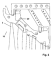
- the present invention relates to a configuration 10 for controlling flow instabilities in the last stage rotor blades 2 of a steam turbine when the turbine operates at low volumetric conditions, particularly during starting and low load conditions.
- the configuration 10 is such that a plurality of passages 20 are located in the vane carrier 1 of the last stage of the steam turbine, these passages 20 being located at specific positions at the circumference of the vane carrier 1. Through these passages 20, a fluid is blown onto the rotor blades 2.
- the number of passages 20 and their specific positions are defined in such a way that the fluid blown through the passages 20 is directed towards the rotor blades 2 avoiding rotating stability problems in these last stage rotor blades 2 that produce undesired vibration effects on them.
- Figure 1 shows the flow pattern in the last stage low pressure vane carrier 1 during starting and low load conditions (up to around 10% of the design mass flow), showing that the flow structure is very disorderly.
- the through flow in the vane carrier 1 adopts a wavy shape, as shown in Figure 1 , existing large toroidal vortex structures 30: the last stage low pressure vane carrier 1 actually acts as a radial pump and there is net energy input to the stage.
- a solution is to use water sprays injected in the exhaust diffuser to cool the exhaust casing vane carrier walls and last stage blades, but this solution has not been found to be reliable.
- the purpose of the configuration 10 of the invention is to design the passages 20 to eliminate the rotating flow instabilities in the last stage rotor blades 2 during starting and low load conditions of the steam turbine.
- the positions of the passages 20 upstream of the last stage rotor blade 2 is such that the injection flow is directed through the last stage vane carrier 1 to approximately 80% last stage blade height, as measured from the blade platform to the tip, so as to blow into the torodial vortex 30 typically formed upstream of the rotor blade 2 tip region.
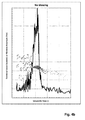
- Figs. 4a , 4b and 4c shows a series of tests that demonstrate the surprising effect that a negative injection angle results in a more stable and steady separated flow, decoupled from resonance can be seen.
- the tests were carried out in a one third scale model low pressure steam turbine over a range of mass flow rates and condenser pressure. During the tests measurement were made of last stage blade stress using a strain gauge located on the surface of the last stage blade. Results of these measurements are shown as lines representation vibrational amplitude in Figs. 4a , 4b and 4c .
- An additional dynamic pressure sensor acting as a microphone, was additional located in the flow to detect the formation of the rotating events that can give rise to blade vibration. From the pressure signal it was possible to determine frequency, which is transformable into fractional speed, and represent this as spheres in Figs 4a , 4b and 4c . The amplitude from the pressure sensor was then used in Figs. 4a , 4b and 4c to define the size of the grey spheres on each of the graphs.
- the fluid injected from the passages 20, which preferably is steam, is such that the injection angle incident on the rotor blades 2 forms an angle from zero to -90 degrees, the negative angle being taken in the direction counter to the turbine rotor rotation.
- the preferred injection angle range is -45 to -75 degrees, the most preferred injection angle being -60 degrees.
- the flow injected from the passages 20 is up to 10% of the mainstream flow.
- the number of passages 20 relative to the number of rotor blades 2 is set to provide sufficient stabilization of the rotating events. In the case of the test results given, 12 passages were used. Other embodiments of this invention may use a different number of passages to obtain sufficient stabilization.
- the passages are equally spaced around the circumference. In an alternative embodiment the passages are unevenly spaced around the circumference for enhanced performance or for practical considerations.
- the following parameters influence the performance of the configuration 10 of the invention maintaining the trajectory length of the fluid blown from the passages 20 as small as possible; maintaining the velocity of the fluid injected as high as possible; and maximizing the circumferential extent of the passages 20 in the vane carrier 1.
- the passages 20 are circumferentially shaped to increase the circumferential coverage in the vane carrier 1 as shown in Fig. 2 .
Landscapes
- Engineering & Computer Science (AREA)
- Mechanical Engineering (AREA)
- General Engineering & Computer Science (AREA)
- Turbine Rotor Nozzle Sealing (AREA)
- Control Of Turbines (AREA)
Abstract
Description
- The present invention relates to a configuration of the last stage in a steam turbine for controlling rotating flow instabilities in the last stage rotor blades when the steam turbine operates at low volumetric flow conditions, particularly during starting and low load conditions.
- Stalling is a known phenomenon based on the sudden decrease of the load exerted onto a profile subjected to a flow: in steam turbines, the stalling phenomenon induces rotating flow instabilities in the rotor blades, particularly in the last stage rotor blades.
- In steam turbines, during starting and low load conditions (up to around 10% of the design mass flow), the flow structure is very disorderly, particularly in the low pressure stage of the steam turbine: this flow is centrifuged radially outwards in the rotor blades, the flow being centrifuged radially inwards in the stator blades. At low load conditions there is high flow incidence onto the last stage rotor blades, which can cause flow separation from the rotor blades surface and flow instabilities, these instabilities are commonly found to rotate at about one half of the blade rotational speed. At this point the flow field also contains large toroidal vortex structures are set up. These rotating instabilities can couple with the natural frequency of the rotor blades and produce undesirable vibration effects.
- Some solutions known in the prior art minimize this problem by removing the last stage low pressure channel, which is replaced by a newly designed part, frequently comprising a perforated plate. However, this results in a great loss of efficiency in the steam turbine, also being very costly. Besides, it is possible that the rotating flow instabilities move upstream and makes that other stages in the steam turbine fail.
- The invention is oriented towards solving these problems.
- The present invention relates to a configuration for controlling flow instabilities in steam turbines when they operate at low volumetric conditions, particularly during starting and low load conditions. The configuration of the invention comprises a plurality of passages located in the last stage vane carrier of the low pressure stage of the steam turbine, these passages being located at specific positions at the vane carrier: through these passages, a fluid is blown onto the rotating blades to counteract rotating flow instabilities in them. The number of passages and their specific positions are defined in such a way that the fluid blown is directed towards the rotor blades and preventing the excitation.
- According to one embodiment of the invention, the passages are shaped circumferentially in order to increase the circumferential coverage of each passage.
- The fluid blown through the passages into the rotor blades is such that the swirl injection angle incident on the rotor blades forms an angle from zero to -90 degrees. The positive angle being taken in the direction of the turbine rotor rotation, with zero degrees being axial, wherein in the axial/radial plane the jet is directed downwards from the outer flow boundary.
- With the configuration of the invention, a near complete elimination of the rotor blade vibration is achieved.
- The foregoing objects and many of the attendant advantages of this invention will become more readily appreciated as the same becomes better understood by reference to the following detailed description when taken in conjunction with the accompanying drawings, wherein:
-
Figure 1 shows the characteristics of low flow in a steam turbine. Radial movements of the through flow can be seen together with the recirculation zones created; -
Figure 2 shows an embodiment of the invention where the passages are shaped in the circumferential direction to increase the flow coverage for each passage provided; -
Figure 3 shows schematically the configuration of the invention for controlling flow instabilities in the last stage rotor blades of a steam turbine when the turbine operates at low volumetric conditions; -
Figures 4a,b,c shows the influence of injection swirl angle on Volumetric flow versus fractional Speed and Vibration amplitude; and -
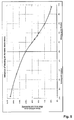
Figure 5 shows the influence of blowing mass flow on dynamic blade stress. - The present invention relates to a
configuration 10 for controlling flow instabilities in the laststage rotor blades 2 of a steam turbine when the turbine operates at low volumetric conditions, particularly during starting and low load conditions. Theconfiguration 10 is such that a plurality ofpassages 20 are located in thevane carrier 1 of the last stage of the steam turbine, thesepassages 20 being located at specific positions at the circumference of thevane carrier 1. Through thesepassages 20, a fluid is blown onto therotor blades 2. The number ofpassages 20 and their specific positions are defined in such a way that the fluid blown through thepassages 20 is directed towards therotor blades 2 avoiding rotating stability problems in these laststage rotor blades 2 that produce undesired vibration effects on them. -
Figure 1 shows the flow pattern in the last stage lowpressure vane carrier 1 during starting and low load conditions (up to around 10% of the design mass flow), showing that the flow structure is very disorderly. The through flow in thevane carrier 1 adopts a wavy shape, as shown inFigure 1 , existing large toroidal vortex structures 30: the last stage lowpressure vane carrier 1 actually acts as a radial pump and there is net energy input to the stage. According to the known prior art, a solution is to use water sprays injected in the exhaust diffuser to cool the exhaust casing vane carrier walls and last stage blades, but this solution has not been found to be reliable. - The purpose of the
configuration 10 of the invention is to design thepassages 20 to eliminate the rotating flow instabilities in the laststage rotor blades 2 during starting and low load conditions of the steam turbine. - The positions of the
passages 20 upstream of the laststage rotor blade 2 is such that the injection flow is directed through the laststage vane carrier 1 to approximately 80% last stage blade height, as measured from the blade platform to the tip, so as to blow into thetorodial vortex 30 typically formed upstream of therotor blade 2 tip region. - From the series of
Figs. 4a ,4b and4c shows a series of tests that demonstrate the surprising effect that a negative injection angle results in a more stable and steady separated flow, decoupled from resonance can be seen. The tests were carried out in a one third scale model low pressure steam turbine over a range of mass flow rates and condenser pressure. During the tests measurement were made of last stage blade stress using a strain gauge located on the surface of the last stage blade. Results of these measurements are shown as lines representation vibrational amplitude inFigs. 4a ,4b and4c . - An additional dynamic pressure sensor, acting as a microphone, was additional located in the flow to detect the formation of the rotating events that can give rise to blade vibration. From the pressure signal it was possible to determine frequency, which is transformable into fractional speed, and represent this as spheres in
Figs 4a ,4b and4c . The amplitude from the pressure sensor was then used inFigs. 4a ,4b and4c to define the size of the grey spheres on each of the graphs. - Plots were then produced of fractional speed and vibrational amplitude versus volumetric flow for each of the cases of +60 degree injection as shown in
Fig 4a no injection as shown inFig. 4b , and -60 degree injection as shown inFig. 4c , wherein volumetric flow is defined as the average axial flow velocity leaving the last stage divided by the blade root speed. - In each case, measured high vibration amplitude events were found to coincide with higher dynamic pressure amplitude and loss of its frequency scatter. With an injection at +60 degrees appeared to exacerbate vibrational amplitude, as seen in
Fig. 4a when compared with the no injection case shown inFig. 4b . With an injection angle of -60 it was possible to eliminate blade vibration, as can been seen inFig. 4c . As further shown inFig. 5 , a negative injection rate has a positive effect on reducing relative dynamic stress even at very shallow injection angles. - According to an embodiment, the fluid injected from the
passages 20, which preferably is steam, is such that the injection angle incident on therotor blades 2 forms an angle from zero to -90 degrees, the negative angle being taken in the direction counter to the turbine rotor rotation. According to a further embodiment of the invention, the preferred injection angle range is -45 to -75 degrees, the most preferred injection angle being -60 degrees. According to still a further embodiment of the invention. The flow injected from thepassages 20 is up to 10% of the mainstream flow. - The number of
passages 20 relative to the number ofrotor blades 2 is set to provide sufficient stabilization of the rotating events. In the case of the test results given, 12 passages were used. Other embodiments of this invention may use a different number of passages to obtain sufficient stabilization. - In an embodiment of this invention the passages are equally spaced around the circumference. In an alternative embodiment the passages are unevenly spaced around the circumference for enhanced performance or for practical considerations.
- Together with the injection angle the velocity of the fluid blown onto the
rotor blades 2 is also important. - Therefore, the following parameters influence the performance of the
configuration 10 of the invention maintaining the trajectory length of the fluid blown from thepassages 20 as small as possible; maintaining the velocity of the fluid injected as high as possible; and maximizing the circumferential extent of thepassages 20 in thevane carrier 1. - It is difficult to weight the above-cited parameters and, therefore, a different optimum absolute injection angle exists and has to be calculated for each specific case.
- According to one embodiment of the invention, the
passages 20 are circumferentially shaped to increase the circumferential coverage in thevane carrier 1 as shown inFig. 2 . - With the
configuration 10 of the invention, a major minimization of therotor blades 2 vibration and of their critical resonance is achieved. Moreover, the use ofpassages 20 to control rotating flow instabilities constitutes a way of controlling the flow instabilities rotating problem and does not lead to a loss in the efficiency at design full-load conditions. - Although the present invention has been fully described in connection with preferred embodiments, it is evident that modifications may be introduced within the scope thereof, not considering this as limited by these embodiments, but by the contents of the following claims.
- 1
- Last stage vane carrier
- 2
- Rotor blades
- 10
- Configuration for controlling flow instabilities
- 20
- Passages
- 30
- Toroidal vortex in the vane carrier
Claims (12)
- Configuration (10) of a last stage of a steam turbine where rotor blades (2) rotate encircled by a vane carrier (1), characterized in that a plurality of passages (20) are located in the vane carrier (1), such that a fluid is blown through these passages (20) upstream of the rotor blades (2) and arranged to form a flow that impinges onto the rotor blades (2) with an injection angle of between zero to -90 degrees against the rotation of the rotor blades (2) such that rotating flow instabilities in the rotor blades (2) when the steam turbine operates at low volumetric flow conditions are reduced.
- Configuration (10) according to claim 1, wherein the passages are configured and arranged to blow fluid towards a point that is approximately 80% of a height of the last stage rotor blade (2) taken from a base to a tip of the rotor blade (2).
- Configuration (10) according to claim 1, wherein the plurality of passages (20) are circumferentially uniformly spaced in the vane carrier (1).
- Configuration (10) according to claim 3, wherein the plurality of passages (20) circumferentially uniformly spaced in the vane carrier (1) number eight.
- Configuration (10) according to claim 3, wherein the plurality of passages (20) circumferentially uniformly spaced in the vane carrier (1) number twelve.
- Configuration (10) according to claim 1, wherein the passages (20) are circumferentially shaped in such a way that a circumferential coverage in the vane carrier (1) is increased.
- Configuration (10) according to claim 1, wherein the injection angle is in a range from -45 to -75 degrees.
- Configuration (10) according to claim 1, wherein the injection angle is about -60 degrees.
- Configuration (10) according to claim 1 wherein in that the flow injected through the passages (20) is up to 10% of the mainstream flow circulating through the rotor blades (2) and the vane carrier (1).
- Configuration (10) according to claim 1 wherein in that the flow injected through the passages (20) is approximately 10% of the mainstream flow circulating through the rotor blades (2) and the vane carrier (1).
- Configuration (10) according to claim 1, wherein the fluid blown through the passages (20) is steam.
- A steam turbine comprising a last stage configuration (10) according to any of claims 1 to 10.
Priority Applications (1)
| Application Number | Priority Date | Filing Date | Title |
|---|---|---|---|
| EP14170721.6A EP2816199B1 (en) | 2013-06-17 | 2014-06-02 | Control of low volumetric flow instabilities in steam turbines |
Applications Claiming Priority (2)
| Application Number | Priority Date | Filing Date | Title |
|---|---|---|---|
| EP13172223 | 2013-06-17 | ||
| EP14170721.6A EP2816199B1 (en) | 2013-06-17 | 2014-06-02 | Control of low volumetric flow instabilities in steam turbines |
Publications (3)
| Publication Number | Publication Date |
|---|---|
| EP2816199A2 true EP2816199A2 (en) | 2014-12-24 |
| EP2816199A3 EP2816199A3 (en) | 2015-03-04 |
| EP2816199B1 EP2816199B1 (en) | 2021-09-01 |
Family
ID=48669768
Family Applications (1)
| Application Number | Title | Priority Date | Filing Date |
|---|---|---|---|
| EP14170721.6A Active EP2816199B1 (en) | 2013-06-17 | 2014-06-02 | Control of low volumetric flow instabilities in steam turbines |
Country Status (5)
| Country | Link |
|---|---|
| US (1) | US20140369815A1 (en) |
| EP (1) | EP2816199B1 (en) |
| JP (1) | JP6239447B2 (en) |
| CN (1) | CN104234757B (en) |
| IN (1) | IN2014DE01617A (en) |
Cited By (1)
| Publication number | Priority date | Publication date | Assignee | Title |
|---|---|---|---|---|
| WO2019236062A1 (en) | 2018-06-05 | 2019-12-12 | Siemens Energy, Inc. | Arrangement of a last stage with flow blockers and corresponding method for suppressing rotating flow instability cells |
Families Citing this family (7)
| Publication number | Priority date | Publication date | Assignee | Title |
|---|---|---|---|---|
| US11193942B2 (en) * | 2014-12-09 | 2021-12-07 | Anna Villarreal | Methods and devices for female health monitoring |
| US10662802B2 (en) | 2018-01-02 | 2020-05-26 | General Electric Company | Controlled flow guides for turbines |
| JP6916755B2 (en) * | 2018-03-09 | 2021-08-11 | 三菱重工業株式会社 | Rotating machine |
| EP3816397B1 (en) * | 2019-10-31 | 2023-05-10 | General Electric Company | Controlled flow turbine blades |
| CN112699505B (en) * | 2020-12-28 | 2022-11-25 | 哈尔滨汽轮机厂有限责任公司 | Dynamic stress finite element calculation method for long blade of low-pressure cylinder of nuclear power unit |
| CN113153453B (en) * | 2021-03-02 | 2022-10-11 | 哈尔滨工业大学 | Steam turbine last stage blade volume flow estimation method, flutter early warning method, system and device |
| CN116842644A (en) * | 2022-03-23 | 2023-10-03 | 三河发电有限责任公司 | A safety check method for zero-output modification of low-pressure cylinders |
Family Cites Families (19)
| Publication number | Priority date | Publication date | Assignee | Title |
|---|---|---|---|---|
| JPS57180101U (en) * | 1981-05-12 | 1982-11-15 | ||
| JPS5813105A (en) * | 1981-07-16 | 1983-01-25 | Toshiba Corp | Steam turbine |
| JPS63179101A (en) * | 1987-01-20 | 1988-07-23 | Mitsubishi Heavy Ind Ltd | Axial flow turbine |
| JPH0430203A (en) * | 1990-05-25 | 1992-02-03 | Fanuc Ltd | Control system for acceleration/deceleration time constant of robot |
| JPH0430203U (en) * | 1990-07-09 | 1992-03-11 | ||
| JPH04308301A (en) * | 1991-04-03 | 1992-10-30 | Mitsubishi Heavy Ind Ltd | Vibration preventing method for steam turbine blade |
| US5486091A (en) * | 1994-04-19 | 1996-01-23 | United Technologies Corporation | Gas turbine airfoil clocking |
| JP3816150B2 (en) * | 1995-07-18 | 2006-08-30 | 株式会社荏原製作所 | Centrifugal fluid machinery |
| JP3786458B2 (en) * | 1996-01-19 | 2006-06-14 | 株式会社東芝 | Axial turbine blade |
| CH697101A5 (en) * | 2004-01-31 | 2008-04-30 | Zhengji Zhang | Method for elimination of flow instability and rotary replacements in radial, diagonal or axial fluid-flow machines, particularly turbomachines, centrifugal pumps or compressor, involves diverting leakage current by diagonal gap |
| US7594388B2 (en) * | 2005-06-06 | 2009-09-29 | General Electric Company | Counterrotating turbofan engine |
| JP2005299680A (en) * | 2005-07-11 | 2005-10-27 | Toshiba Corp | Axial turbine blade |
| US7744343B2 (en) * | 2006-09-21 | 2010-06-29 | General Electric Company | Method and apparatus for controlling the operation of a steam turbine |
| US8322972B2 (en) * | 2009-11-05 | 2012-12-04 | General Electric Company | Steampath flow separation reduction system |
| EP2434164A1 (en) * | 2010-09-24 | 2012-03-28 | Siemens Aktiengesellschaft | Variable casing treatment |
| US10072522B2 (en) * | 2011-07-14 | 2018-09-11 | Honeywell International Inc. | Compressors with integrated secondary air flow systems |
| US20130064665A1 (en) * | 2011-09-13 | 2013-03-14 | General Electric Company | Low pressure steam turbine including pivotable nozzle |
| JP2013060931A (en) * | 2011-09-15 | 2013-04-04 | Toshiba Corp | Steam turbine |
| US20130280050A1 (en) * | 2012-04-18 | 2013-10-24 | General Electric Company | Turbine vibration reduction system |
-
2014
- 2014-06-02 EP EP14170721.6A patent/EP2816199B1/en active Active
- 2014-06-16 US US14/305,316 patent/US20140369815A1/en not_active Abandoned
- 2014-06-16 IN IN1617DE2014 patent/IN2014DE01617A/en unknown
- 2014-06-17 CN CN201410269622.4A patent/CN104234757B/en active Active
- 2014-06-17 JP JP2014124549A patent/JP6239447B2/en active Active
Non-Patent Citations (1)
| Title |
|---|
| None |
Cited By (1)
| Publication number | Priority date | Publication date | Assignee | Title |
|---|---|---|---|---|
| WO2019236062A1 (en) | 2018-06-05 | 2019-12-12 | Siemens Energy, Inc. | Arrangement of a last stage with flow blockers and corresponding method for suppressing rotating flow instability cells |
Also Published As
| Publication number | Publication date |
|---|---|
| JP6239447B2 (en) | 2017-11-29 |
| EP2816199B1 (en) | 2021-09-01 |
| JP2015001228A (en) | 2015-01-05 |
| EP2816199A3 (en) | 2015-03-04 |
| CN104234757B (en) | 2016-10-05 |
| CN104234757A (en) | 2014-12-24 |
| US20140369815A1 (en) | 2014-12-18 |
| IN2014DE01617A (en) | 2015-06-19 |
Similar Documents
| Publication | Publication Date | Title |
|---|---|---|
| EP2816199B1 (en) | Control of low volumetric flow instabilities in steam turbines | |
| RU2264541C2 (en) | Method of modification of steam turbine rotor blade, steam turbine rotor blade and multistage steam turbine | |
| Camp et al. | 1997 best paper award—Turbomachinery committee: A study of spike and modal stall phenomena in a low-speed axial compressor | |
| JP2021050739A (en) | Biased passage in diffuser and corresponding method for designing such a diffuser | |
| US10443626B2 (en) | Non uniform vane spacing | |
| US9488064B2 (en) | Turbomachine with variable-pitch vortex generator | |
| JP6971564B2 (en) | Turbomachinery and turbine nozzles for it | |
| CA2141544A1 (en) | Process and device for monitoring and for controlling of a compressor | |
| US20110274537A1 (en) | Blade excitation reduction method and arrangement | |
| CN103987956B (en) | Compact blades for a runner of a Farfield turbine and method of configuring the runner | |
| KR20150131247A (en) | Vane arrangement having alternating vanes with different trailing edge profile | |
| Wang et al. | The effects on stability, performance, and tip leakage flow of recirculating casing treatment in a subsonic axial flow compressor | |
| Yue et al. | Experimental investigation of the unsteady tip clearance flow in a low-speed axial contra-rotating compressor | |
| Xu et al. | Experimental research on inlet steady swirl distortion in an axial compressor with non-uniform tip clearance | |
| JP6804265B2 (en) | System for integrating turbine parts | |
| Alone et al. | Performance characterization of the effect of axial positioning of bend skewed casing treatment retrofitted to a transonic axial flow compressor | |
| Hassan | Influence of the volute design parameters on the performance of a centrifugal compressor of an aircraft turbocharger | |
| Cai et al. | Aerodynamic and aeroacoustic performance of a skewed rotor | |
| US11788557B1 (en) | Centrifugal acceleration stabilizer | |
| Xin et al. | Numerical investigation of the flow field and aerodynamic load on impellers in centrifugal compressor with different radial inlets | |
| Nishioka et al. | Rotor-tip flow fields near inception point of rotating instability in an axial-flow fan | |
| Alone et al. | Experimental investigation on the effect of porosity of bend skewed casing treatment on a single stage transonic axial flow compressor | |
| Li et al. | Investigation of the wake effect from the centrifugal splitter impeller blade to the vaned diffuser | |
| Nishioka et al. | Influence of rotor stagger angle on rotating stall inception in an axial-flow fan | |
| Buffaz et al. | Impact of Tip Clearance Size and Rotation Speed on the Surge Onset in a High Pressure Centrifugal Compressor |
Legal Events
| Date | Code | Title | Description |
|---|---|---|---|
| PUAI | Public reference made under article 153(3) epc to a published international application that has entered the european phase |
Free format text: ORIGINAL CODE: 0009012 |
|
| 17P | Request for examination filed |
Effective date: 20140602 |
|
| AK | Designated contracting states |
Kind code of ref document: A2 Designated state(s): AL AT BE BG CH CY CZ DE DK EE ES FI FR GB GR HR HU IE IS IT LI LT LU LV MC MK MT NL NO PL PT RO RS SE SI SK SM TR |
|
| AX | Request for extension of the european patent |
Extension state: BA ME |
|
| PUAL | Search report despatched |
Free format text: ORIGINAL CODE: 0009013 |
|
| AK | Designated contracting states |
Kind code of ref document: A3 Designated state(s): AL AT BE BG CH CY CZ DE DK EE ES FI FR GB GR HR HU IE IS IT LI LT LU LV MC MK MT NL NO PL PT RO RS SE SI SK SM TR |
|
| AX | Request for extension of the european patent |
Extension state: BA ME |
|
| RIC1 | Information provided on ipc code assigned before grant |
Ipc: F01D 19/00 20060101AFI20150129BHEP Ipc: F01D 9/04 20060101ALI20150129BHEP Ipc: F01D 21/00 20060101ALI20150129BHEP Ipc: F01D 5/16 20060101ALI20150129BHEP Ipc: F01D 25/24 20060101ALI20150129BHEP Ipc: F01D 5/10 20060101ALI20150129BHEP Ipc: F01D 25/06 20060101ALI20150129BHEP Ipc: F01D 5/00 20060101ALI20150129BHEP Ipc: F01D 25/04 20060101ALI20150129BHEP Ipc: F01D 11/10 20060101ALI20150129BHEP |
|
| RAP1 | Party data changed (applicant data changed or rights of an application transferred) |
Owner name: GENERAL ELECTRIC TECHNOLOGY GMBH |
|
| STAA | Information on the status of an ep patent application or granted ep patent |
Free format text: STATUS: EXAMINATION IS IN PROGRESS |
|
| 17Q | First examination report despatched |
Effective date: 20180504 |
|
| GRAP | Despatch of communication of intention to grant a patent |
Free format text: ORIGINAL CODE: EPIDOSNIGR1 |
|
| STAA | Information on the status of an ep patent application or granted ep patent |
Free format text: STATUS: GRANT OF PATENT IS INTENDED |
|
| INTG | Intention to grant announced |
Effective date: 20201120 |
|
| GRAJ | Information related to disapproval of communication of intention to grant by the applicant or resumption of examination proceedings by the epo deleted |
Free format text: ORIGINAL CODE: EPIDOSDIGR1 |
|
| STAA | Information on the status of an ep patent application or granted ep patent |
Free format text: STATUS: EXAMINATION IS IN PROGRESS |
|
| INTC | Intention to grant announced (deleted) | ||
| GRAP | Despatch of communication of intention to grant a patent |
Free format text: ORIGINAL CODE: EPIDOSNIGR1 |
|
| STAA | Information on the status of an ep patent application or granted ep patent |
Free format text: STATUS: GRANT OF PATENT IS INTENDED |
|
| RAP3 | Party data changed (applicant data changed or rights of an application transferred) |
Owner name: GENERAL ELECTRIC TECHNOLOGY GMBH |
|
| INTG | Intention to grant announced |
Effective date: 20210420 |
|
| GRAS | Grant fee paid |
Free format text: ORIGINAL CODE: EPIDOSNIGR3 |
|
| GRAA | (expected) grant |
Free format text: ORIGINAL CODE: 0009210 |
|
| STAA | Information on the status of an ep patent application or granted ep patent |
Free format text: STATUS: THE PATENT HAS BEEN GRANTED |
|
| AK | Designated contracting states |
Kind code of ref document: B1 Designated state(s): AL AT BE BG CH CY CZ DE DK EE ES FI FR GB GR HR HU IE IS IT LI LT LU LV MC MK MT NL NO PL PT RO RS SE SI SK SM TR |
|
| REG | Reference to a national code |
Ref country code: GB Ref legal event code: FG4D |
|
| REG | Reference to a national code |
Ref country code: CH Ref legal event code: EP Ref country code: AT Ref legal event code: REF Ref document number: 1426459 Country of ref document: AT Kind code of ref document: T Effective date: 20210915 |
|
| REG | Reference to a national code |
Ref country code: DE Ref legal event code: R096 Ref document number: 602014079801 Country of ref document: DE |
|
| REG | Reference to a national code |
Ref country code: IE Ref legal event code: FG4D |
|
| REG | Reference to a national code |
Ref country code: LT Ref legal event code: MG9D |
|
| REG | Reference to a national code |
Ref country code: NL Ref legal event code: MP Effective date: 20210901 |
|
| PG25 | Lapsed in a contracting state [announced via postgrant information from national office to epo] |
Ref country code: LT Free format text: LAPSE BECAUSE OF FAILURE TO SUBMIT A TRANSLATION OF THE DESCRIPTION OR TO PAY THE FEE WITHIN THE PRESCRIBED TIME-LIMIT Effective date: 20210901 Ref country code: BG Free format text: LAPSE BECAUSE OF FAILURE TO SUBMIT A TRANSLATION OF THE DESCRIPTION OR TO PAY THE FEE WITHIN THE PRESCRIBED TIME-LIMIT Effective date: 20211201 Ref country code: FI Free format text: LAPSE BECAUSE OF FAILURE TO SUBMIT A TRANSLATION OF THE DESCRIPTION OR TO PAY THE FEE WITHIN THE PRESCRIBED TIME-LIMIT Effective date: 20210901 Ref country code: ES Free format text: LAPSE BECAUSE OF FAILURE TO SUBMIT A TRANSLATION OF THE DESCRIPTION OR TO PAY THE FEE WITHIN THE PRESCRIBED TIME-LIMIT Effective date: 20210901 Ref country code: NO Free format text: LAPSE BECAUSE OF FAILURE TO SUBMIT A TRANSLATION OF THE DESCRIPTION OR TO PAY THE FEE WITHIN THE PRESCRIBED TIME-LIMIT Effective date: 20211201 Ref country code: HR Free format text: LAPSE BECAUSE OF FAILURE TO SUBMIT A TRANSLATION OF THE DESCRIPTION OR TO PAY THE FEE WITHIN THE PRESCRIBED TIME-LIMIT Effective date: 20210901 Ref country code: SE Free format text: LAPSE BECAUSE OF FAILURE TO SUBMIT A TRANSLATION OF THE DESCRIPTION OR TO PAY THE FEE WITHIN THE PRESCRIBED TIME-LIMIT Effective date: 20210901 Ref country code: RS Free format text: LAPSE BECAUSE OF FAILURE TO SUBMIT A TRANSLATION OF THE DESCRIPTION OR TO PAY THE FEE WITHIN THE PRESCRIBED TIME-LIMIT Effective date: 20210901 |
|
| REG | Reference to a national code |
Ref country code: AT Ref legal event code: MK05 Ref document number: 1426459 Country of ref document: AT Kind code of ref document: T Effective date: 20210901 |
|
| PG25 | Lapsed in a contracting state [announced via postgrant information from national office to epo] |
Ref country code: PL Free format text: LAPSE BECAUSE OF FAILURE TO SUBMIT A TRANSLATION OF THE DESCRIPTION OR TO PAY THE FEE WITHIN THE PRESCRIBED TIME-LIMIT Effective date: 20210901 Ref country code: LV Free format text: LAPSE BECAUSE OF FAILURE TO SUBMIT A TRANSLATION OF THE DESCRIPTION OR TO PAY THE FEE WITHIN THE PRESCRIBED TIME-LIMIT Effective date: 20210901 Ref country code: GR Free format text: LAPSE BECAUSE OF FAILURE TO SUBMIT A TRANSLATION OF THE DESCRIPTION OR TO PAY THE FEE WITHIN THE PRESCRIBED TIME-LIMIT Effective date: 20211202 |
|
| PG25 | Lapsed in a contracting state [announced via postgrant information from national office to epo] |
Ref country code: AT Free format text: LAPSE BECAUSE OF FAILURE TO SUBMIT A TRANSLATION OF THE DESCRIPTION OR TO PAY THE FEE WITHIN THE PRESCRIBED TIME-LIMIT Effective date: 20210901 |
|
| PG25 | Lapsed in a contracting state [announced via postgrant information from national office to epo] |
Ref country code: IS Free format text: LAPSE BECAUSE OF FAILURE TO SUBMIT A TRANSLATION OF THE DESCRIPTION OR TO PAY THE FEE WITHIN THE PRESCRIBED TIME-LIMIT Effective date: 20220101 Ref country code: SM Free format text: LAPSE BECAUSE OF FAILURE TO SUBMIT A TRANSLATION OF THE DESCRIPTION OR TO PAY THE FEE WITHIN THE PRESCRIBED TIME-LIMIT Effective date: 20210901 Ref country code: SK Free format text: LAPSE BECAUSE OF FAILURE TO SUBMIT A TRANSLATION OF THE DESCRIPTION OR TO PAY THE FEE WITHIN THE PRESCRIBED TIME-LIMIT Effective date: 20210901 Ref country code: RO Free format text: LAPSE BECAUSE OF FAILURE TO SUBMIT A TRANSLATION OF THE DESCRIPTION OR TO PAY THE FEE WITHIN THE PRESCRIBED TIME-LIMIT Effective date: 20210901 Ref country code: PT Free format text: LAPSE BECAUSE OF FAILURE TO SUBMIT A TRANSLATION OF THE DESCRIPTION OR TO PAY THE FEE WITHIN THE PRESCRIBED TIME-LIMIT Effective date: 20220103 Ref country code: NL Free format text: LAPSE BECAUSE OF FAILURE TO SUBMIT A TRANSLATION OF THE DESCRIPTION OR TO PAY THE FEE WITHIN THE PRESCRIBED TIME-LIMIT Effective date: 20210901 Ref country code: EE Free format text: LAPSE BECAUSE OF FAILURE TO SUBMIT A TRANSLATION OF THE DESCRIPTION OR TO PAY THE FEE WITHIN THE PRESCRIBED TIME-LIMIT Effective date: 20210901 Ref country code: AL Free format text: LAPSE BECAUSE OF FAILURE TO SUBMIT A TRANSLATION OF THE DESCRIPTION OR TO PAY THE FEE WITHIN THE PRESCRIBED TIME-LIMIT Effective date: 20210901 |
|
| REG | Reference to a national code |
Ref country code: DE Ref legal event code: R097 Ref document number: 602014079801 Country of ref document: DE |
|
| PLBE | No opposition filed within time limit |
Free format text: ORIGINAL CODE: 0009261 |
|
| STAA | Information on the status of an ep patent application or granted ep patent |
Free format text: STATUS: NO OPPOSITION FILED WITHIN TIME LIMIT |
|
| PG25 | Lapsed in a contracting state [announced via postgrant information from national office to epo] |
Ref country code: DK Free format text: LAPSE BECAUSE OF FAILURE TO SUBMIT A TRANSLATION OF THE DESCRIPTION OR TO PAY THE FEE WITHIN THE PRESCRIBED TIME-LIMIT Effective date: 20210901 |
|
| 26N | No opposition filed |
Effective date: 20220602 |
|
| PG25 | Lapsed in a contracting state [announced via postgrant information from national office to epo] |
Ref country code: SI Free format text: LAPSE BECAUSE OF FAILURE TO SUBMIT A TRANSLATION OF THE DESCRIPTION OR TO PAY THE FEE WITHIN THE PRESCRIBED TIME-LIMIT Effective date: 20210901 |
|
| PG25 | Lapsed in a contracting state [announced via postgrant information from national office to epo] |
Ref country code: MC Free format text: LAPSE BECAUSE OF FAILURE TO SUBMIT A TRANSLATION OF THE DESCRIPTION OR TO PAY THE FEE WITHIN THE PRESCRIBED TIME-LIMIT Effective date: 20210901 |
|
| REG | Reference to a national code |
Ref country code: CH Ref legal event code: PL |
|
| REG | Reference to a national code |
Ref country code: BE Ref legal event code: MM Effective date: 20220630 |
|
| PG25 | Lapsed in a contracting state [announced via postgrant information from national office to epo] |
Ref country code: LU Free format text: LAPSE BECAUSE OF NON-PAYMENT OF DUE FEES Effective date: 20220602 Ref country code: LI Free format text: LAPSE BECAUSE OF NON-PAYMENT OF DUE FEES Effective date: 20220630 Ref country code: IE Free format text: LAPSE BECAUSE OF NON-PAYMENT OF DUE FEES Effective date: 20220602 Ref country code: CH Free format text: LAPSE BECAUSE OF NON-PAYMENT OF DUE FEES Effective date: 20220630 |
|
| PG25 | Lapsed in a contracting state [announced via postgrant information from national office to epo] |
Ref country code: BE Free format text: LAPSE BECAUSE OF NON-PAYMENT OF DUE FEES Effective date: 20220630 |
|
| P01 | Opt-out of the competence of the unified patent court (upc) registered |
Effective date: 20230523 |
|
| PG25 | Lapsed in a contracting state [announced via postgrant information from national office to epo] |
Ref country code: HU Free format text: LAPSE BECAUSE OF FAILURE TO SUBMIT A TRANSLATION OF THE DESCRIPTION OR TO PAY THE FEE WITHIN THE PRESCRIBED TIME-LIMIT; INVALID AB INITIO Effective date: 20140602 |
|
| PG25 | Lapsed in a contracting state [announced via postgrant information from national office to epo] |
Ref country code: MK Free format text: LAPSE BECAUSE OF FAILURE TO SUBMIT A TRANSLATION OF THE DESCRIPTION OR TO PAY THE FEE WITHIN THE PRESCRIBED TIME-LIMIT Effective date: 20210901 Ref country code: CY Free format text: LAPSE BECAUSE OF FAILURE TO SUBMIT A TRANSLATION OF THE DESCRIPTION OR TO PAY THE FEE WITHIN THE PRESCRIBED TIME-LIMIT Effective date: 20210901 |
|
| PG25 | Lapsed in a contracting state [announced via postgrant information from national office to epo] |
Ref country code: TR Free format text: LAPSE BECAUSE OF FAILURE TO SUBMIT A TRANSLATION OF THE DESCRIPTION OR TO PAY THE FEE WITHIN THE PRESCRIBED TIME-LIMIT Effective date: 20210901 |
|
| PG25 | Lapsed in a contracting state [announced via postgrant information from national office to epo] |
Ref country code: MT Free format text: LAPSE BECAUSE OF FAILURE TO SUBMIT A TRANSLATION OF THE DESCRIPTION OR TO PAY THE FEE WITHIN THE PRESCRIBED TIME-LIMIT Effective date: 20210901 |
|
| PGFP | Annual fee paid to national office [announced via postgrant information from national office to epo] |
Ref country code: DE Payment date: 20250520 Year of fee payment: 12 |
|
| PGFP | Annual fee paid to national office [announced via postgrant information from national office to epo] |
Ref country code: GB Payment date: 20250520 Year of fee payment: 12 |
|
| PGFP | Annual fee paid to national office [announced via postgrant information from national office to epo] |
Ref country code: IT Payment date: 20250520 Year of fee payment: 12 |
|
| PGFP | Annual fee paid to national office [announced via postgrant information from national office to epo] |
Ref country code: FR Payment date: 20250520 Year of fee payment: 12 |
|
| PGFP | Annual fee paid to national office [announced via postgrant information from national office to epo] |
Ref country code: CZ Payment date: 20250528 Year of fee payment: 12 |