EP2816126A1 - Heat treatment method - Google Patents
Heat treatment method Download PDFInfo
- Publication number
- EP2816126A1 EP2816126A1 EP13748875.5A EP13748875A EP2816126A1 EP 2816126 A1 EP2816126 A1 EP 2816126A1 EP 13748875 A EP13748875 A EP 13748875A EP 2816126 A1 EP2816126 A1 EP 2816126A1
- Authority
- EP
- European Patent Office
- Prior art keywords
- heat treatment
- heat
- impeller
- covering
- target material
- Prior art date
- Legal status (The legal status is an assumption and is not a legal conclusion. Google has not performed a legal analysis and makes no representation as to the accuracy of the status listed.)
- Withdrawn
Links
Images




Classifications
-
- F—MECHANICAL ENGINEERING; LIGHTING; HEATING; WEAPONS; BLASTING
- F27—FURNACES; KILNS; OVENS; RETORTS
- F27D—DETAILS OR ACCESSORIES OF FURNACES, KILNS, OVENS OR RETORTS, IN SO FAR AS THEY ARE OF KINDS OCCURRING IN MORE THAN ONE KIND OF FURNACE
- F27D7/00—Forming, maintaining or circulating atmospheres in heating chambers
- F27D7/02—Supplying steam, vapour, gases or liquids
-
- C—CHEMISTRY; METALLURGY
- C21—METALLURGY OF IRON
- C21D—MODIFYING THE PHYSICAL STRUCTURE OF FERROUS METALS; GENERAL DEVICES FOR HEAT TREATMENT OF FERROUS OR NON-FERROUS METALS OR ALLOYS; MAKING METAL MALLEABLE, e.g. BY DECARBURISATION OR TEMPERING
- C21D1/00—General methods or devices for heat treatment, e.g. annealing, hardening, quenching or tempering
- C21D1/34—Methods of heating
-
- C—CHEMISTRY; METALLURGY
- C21—METALLURGY OF IRON
- C21D—MODIFYING THE PHYSICAL STRUCTURE OF FERROUS METALS; GENERAL DEVICES FOR HEAT TREATMENT OF FERROUS OR NON-FERROUS METALS OR ALLOYS; MAKING METAL MALLEABLE, e.g. BY DECARBURISATION OR TEMPERING
- C21D1/00—General methods or devices for heat treatment, e.g. annealing, hardening, quenching or tempering
- C21D1/74—Methods of treatment in inert gas, controlled atmosphere, vacuum or pulverulent material
- C21D1/767—Methods of treatment in inert gas, controlled atmosphere, vacuum or pulverulent material with forced gas circulation; Reheating thereof
-
- C—CHEMISTRY; METALLURGY
- C21—METALLURGY OF IRON
- C21D—MODIFYING THE PHYSICAL STRUCTURE OF FERROUS METALS; GENERAL DEVICES FOR HEAT TREATMENT OF FERROUS OR NON-FERROUS METALS OR ALLOYS; MAKING METAL MALLEABLE, e.g. BY DECARBURISATION OR TEMPERING
- C21D1/00—General methods or devices for heat treatment, e.g. annealing, hardening, quenching or tempering
- C21D1/74—Methods of treatment in inert gas, controlled atmosphere, vacuum or pulverulent material
- C21D1/773—Methods of treatment in inert gas, controlled atmosphere, vacuum or pulverulent material under reduced pressure or vacuum
-
- C—CHEMISTRY; METALLURGY
- C21—METALLURGY OF IRON
- C21D—MODIFYING THE PHYSICAL STRUCTURE OF FERROUS METALS; GENERAL DEVICES FOR HEAT TREATMENT OF FERROUS OR NON-FERROUS METALS OR ALLOYS; MAKING METAL MALLEABLE, e.g. BY DECARBURISATION OR TEMPERING
- C21D9/00—Heat treatment, e.g. annealing, hardening, quenching or tempering, adapted for particular articles; Furnaces therefor
-
- C—CHEMISTRY; METALLURGY
- C21—METALLURGY OF IRON
- C21D—MODIFYING THE PHYSICAL STRUCTURE OF FERROUS METALS; GENERAL DEVICES FOR HEAT TREATMENT OF FERROUS OR NON-FERROUS METALS OR ALLOYS; MAKING METAL MALLEABLE, e.g. BY DECARBURISATION OR TEMPERING
- C21D9/00—Heat treatment, e.g. annealing, hardening, quenching or tempering, adapted for particular articles; Furnaces therefor
- C21D9/0068—Heat treatment, e.g. annealing, hardening, quenching or tempering, adapted for particular articles; Furnaces therefor for particular articles not mentioned below
-
- C—CHEMISTRY; METALLURGY
- C21—METALLURGY OF IRON
- C21D—MODIFYING THE PHYSICAL STRUCTURE OF FERROUS METALS; GENERAL DEVICES FOR HEAT TREATMENT OF FERROUS OR NON-FERROUS METALS OR ALLOYS; MAKING METAL MALLEABLE, e.g. BY DECARBURISATION OR TEMPERING
- C21D9/00—Heat treatment, e.g. annealing, hardening, quenching or tempering, adapted for particular articles; Furnaces therefor
- C21D9/52—Heat treatment, e.g. annealing, hardening, quenching or tempering, adapted for particular articles; Furnaces therefor for wires; for strips ; for rods of unlimited length
- C21D9/54—Furnaces for treating strips or wire
- C21D9/663—Bell-type furnaces
- C21D9/667—Multi-station furnaces
- C21D9/67—Multi-station furnaces adapted for treating the charge in vacuum or special atmosphere
-
- C—CHEMISTRY; METALLURGY
- C21—METALLURGY OF IRON
- C21D—MODIFYING THE PHYSICAL STRUCTURE OF FERROUS METALS; GENERAL DEVICES FOR HEAT TREATMENT OF FERROUS OR NON-FERROUS METALS OR ALLOYS; MAKING METAL MALLEABLE, e.g. BY DECARBURISATION OR TEMPERING
- C21D9/00—Heat treatment, e.g. annealing, hardening, quenching or tempering, adapted for particular articles; Furnaces therefor
- C21D9/52—Heat treatment, e.g. annealing, hardening, quenching or tempering, adapted for particular articles; Furnaces therefor for wires; for strips ; for rods of unlimited length
- C21D9/54—Furnaces for treating strips or wire
- C21D9/663—Bell-type furnaces
- C21D9/673—Details, accessories, or equipment peculiar to bell-type furnaces
-
- C—CHEMISTRY; METALLURGY
- C21—METALLURGY OF IRON
- C21D—MODIFYING THE PHYSICAL STRUCTURE OF FERROUS METALS; GENERAL DEVICES FOR HEAT TREATMENT OF FERROUS OR NON-FERROUS METALS OR ALLOYS; MAKING METAL MALLEABLE, e.g. BY DECARBURISATION OR TEMPERING
- C21D9/00—Heat treatment, e.g. annealing, hardening, quenching or tempering, adapted for particular articles; Furnaces therefor
- C21D9/52—Heat treatment, e.g. annealing, hardening, quenching or tempering, adapted for particular articles; Furnaces therefor for wires; for strips ; for rods of unlimited length
- C21D9/54—Furnaces for treating strips or wire
- C21D9/663—Bell-type furnaces
- C21D9/677—Arrangements of heating devices
-
- F—MECHANICAL ENGINEERING; LIGHTING; HEATING; WEAPONS; BLASTING
- F04—POSITIVE - DISPLACEMENT MACHINES FOR LIQUIDS; PUMPS FOR LIQUIDS OR ELASTIC FLUIDS
- F04D—NON-POSITIVE-DISPLACEMENT PUMPS
- F04D29/00—Details, component parts, or accessories
- F04D29/02—Selection of particular materials
- F04D29/023—Selection of particular materials especially adapted for elastic fluid pumps
-
- F—MECHANICAL ENGINEERING; LIGHTING; HEATING; WEAPONS; BLASTING
- F04—POSITIVE - DISPLACEMENT MACHINES FOR LIQUIDS; PUMPS FOR LIQUIDS OR ELASTIC FLUIDS
- F04D—NON-POSITIVE-DISPLACEMENT PUMPS
- F04D29/00—Details, component parts, or accessories
- F04D29/26—Rotors specially for elastic fluids
- F04D29/28—Rotors specially for elastic fluids for centrifugal or helico-centrifugal pumps for radial-flow or helico-centrifugal pumps
- F04D29/284—Rotors specially for elastic fluids for centrifugal or helico-centrifugal pumps for radial-flow or helico-centrifugal pumps for compressors
-
- F—MECHANICAL ENGINEERING; LIGHTING; HEATING; WEAPONS; BLASTING
- F27—FURNACES; KILNS; OVENS; RETORTS
- F27B—FURNACES, KILNS, OVENS OR RETORTS IN GENERAL; OPEN SINTERING OR LIKE APPARATUS
- F27B17/00—Furnaces of a kind not covered by any of groups F27B1/00 - F27B15/00
- F27B17/0016—Chamber type furnaces
- F27B17/0041—Chamber type furnaces specially adapted for burning bricks or pottery
- F27B17/0075—Heating devices therefor
-
- F—MECHANICAL ENGINEERING; LIGHTING; HEATING; WEAPONS; BLASTING
- F27—FURNACES; KILNS; OVENS; RETORTS
- F27B—FURNACES, KILNS, OVENS OR RETORTS IN GENERAL; OPEN SINTERING OR LIKE APPARATUS
- F27B17/00—Furnaces of a kind not covered by any of groups F27B1/00 - F27B15/00
- F27B17/0016—Chamber type furnaces
- F27B17/0083—Chamber type furnaces with means for circulating the atmosphere
-
- F—MECHANICAL ENGINEERING; LIGHTING; HEATING; WEAPONS; BLASTING
- F27—FURNACES; KILNS; OVENS; RETORTS
- F27B—FURNACES, KILNS, OVENS OR RETORTS IN GENERAL; OPEN SINTERING OR LIKE APPARATUS
- F27B5/00—Muffle furnaces; Retort furnaces; Other furnaces in which the charge is held completely isolated
- F27B5/04—Muffle furnaces; Retort furnaces; Other furnaces in which the charge is held completely isolated adapted for treating the charge in vacuum or special atmosphere
-
- C—CHEMISTRY; METALLURGY
- C21—METALLURGY OF IRON
- C21D—MODIFYING THE PHYSICAL STRUCTURE OF FERROUS METALS; GENERAL DEVICES FOR HEAT TREATMENT OF FERROUS OR NON-FERROUS METALS OR ALLOYS; MAKING METAL MALLEABLE, e.g. BY DECARBURISATION OR TEMPERING
- C21D9/00—Heat treatment, e.g. annealing, hardening, quenching or tempering, adapted for particular articles; Furnaces therefor
- C21D9/32—Heat treatment, e.g. annealing, hardening, quenching or tempering, adapted for particular articles; Furnaces therefor for gear wheels, worm wheels, or the like
-
- C—CHEMISTRY; METALLURGY
- C21—METALLURGY OF IRON
- C21D—MODIFYING THE PHYSICAL STRUCTURE OF FERROUS METALS; GENERAL DEVICES FOR HEAT TREATMENT OF FERROUS OR NON-FERROUS METALS OR ALLOYS; MAKING METAL MALLEABLE, e.g. BY DECARBURISATION OR TEMPERING
- C21D9/00—Heat treatment, e.g. annealing, hardening, quenching or tempering, adapted for particular articles; Furnaces therefor
- C21D9/34—Heat treatment, e.g. annealing, hardening, quenching or tempering, adapted for particular articles; Furnaces therefor for tyres; for rims
-
- F—MECHANICAL ENGINEERING; LIGHTING; HEATING; WEAPONS; BLASTING
- F05—INDEXING SCHEMES RELATING TO ENGINES OR PUMPS IN VARIOUS SUBCLASSES OF CLASSES F01-F04
- F05D—INDEXING SCHEME FOR ASPECTS RELATING TO NON-POSITIVE-DISPLACEMENT MACHINES OR ENGINES, GAS-TURBINES OR JET-PROPULSION PLANTS
- F05D2230/00—Manufacture
- F05D2230/40—Heat treatment
-
- F—MECHANICAL ENGINEERING; LIGHTING; HEATING; WEAPONS; BLASTING
- F27—FURNACES; KILNS; OVENS; RETORTS
- F27B—FURNACES, KILNS, OVENS OR RETORTS IN GENERAL; OPEN SINTERING OR LIKE APPARATUS
- F27B5/00—Muffle furnaces; Retort furnaces; Other furnaces in which the charge is held completely isolated
- F27B5/06—Details, accessories or equipment specially adapted for furnaces of these types
- F27B5/16—Arrangements of air or gas supply devices
- F27B2005/166—Means to circulate the atmosphere
- F27B2005/167—Means to circulate the atmosphere the atmosphere being recirculated through the treatment chamber by a turbine
- F27B2005/168—Means to circulate the atmosphere the atmosphere being recirculated through the treatment chamber by a turbine by more than one turbine
Definitions
- the present invention relates to a heat treatment method of a disc-shaped treatment target material.
- an impeller used for a centrifugal compressor or the like is a member requiring high hardness and high toughness since the impeller is exposed to a compression medium while constantly rotating and centrifugal force and high pressure act thereon. For this reason, the impeller is subjected to heat treatment in which it is heated to a predetermined temperature to be tempered within a heating furnace (see Patent Literatures 2 and 3) and is then quenched by blowing a fluid such as nitrogen gas, and thereby has a degree of hardness and toughness suitable for required specifications.
- the impeller is subjected to the heat treatment.
- the degree of heating differs between parts in which the impeller is close to the heaters and parts in which the impeller is distanced from the heaters, thereby generating a temperature distribution in the impeller.
- the impeller is quenched by the nitrogen gas, it is difficult to uniformly blow the nitrogen gas and a flow distribution of nitrogen is wholly generated in the impeller. Accordingly, a temperature distribution is also generated in the impeller.
- a conventional heat treatment is performed in a state in which extra thickness is provided in an impeller and then an uneven portion of the extra thickness is removed by machining and the like, in consideration of the above deformation, so as to correspond to a variation in hardness and toughness generated during the heat treatment.
- reducing the temperature distribution generated during heating of the impeller by installing a heat shield plate for shielding heat such that a part of the impeller facing a heater is not directly affected by the heater during heating of the impeller or by installing a stirring fan for uniformizing an atmosphere in a furnace and a temperature thereof may be considered.
- the present invention has been made in view of the above problems, and an object of the present invention is to provide a heat treatment method of a member to be treated, capable of reducing extra thickness while preventing a heat treatment time from lengthening.
- a heat treatment method of a disc-shaped treatment target material includes a treatment target material covering process of covering an outer peripheral surface of the treatment target material in a circumferential direction with a covering body made of a radiation conversion material which radiates transferred heat as radiant heat, and a heat treatment process of performing heat treatment by heating or cooling the treatment target material covered with the covering body from the periphery.
- the heat treatment process is performed in a state in which the treatment target material is covered in the circumferential direction by the covering body made of the radiation conversion material by the treatment target material covering process. Therefore, after transferred heat enters the covering body and heats the covering body, the heat may be uniformly radiated from the covering body to the treatment target material in the circumferential direction. That is, since the transferred heat is emitted through the covering body instead of directly entering the treatment target material, the covering body may simply block the transferred heat, and the heat that is unevenly transferred to the covering body in the circumferential direction by convection may uniformly heat the entire covering body by heat conduction within the covering body.
- the covering body is made of the radiation conversion material
- the covering body which is uniformly heated by the heat conduction, may uniformly radiate heat to the treatment target material by radiant heat transfer in the circumferential direction. Therefore, it may be possible to prevent the required time for the heat treatment from lengthening and to achieve heat uniformizing in the heat treatment process.
- a member made of the radiation conversion material having permeability may be used as the covering body, and in the heat treatment process, a fluid in a heat treatment atmosphere may flow from the outside of the covering body to the treatment target material due to permeability of the covering body.
- the covering body is made of the radiation conversion material having permeability, it may be possible to suppress a fluid from stagnating between the covering body and the treatment target material and to reduce the time for the heat treatment.
- the treatment target material may also be covered from an axial direction by the covering body.
- the covering body covers the treatment target material from an axial direction in addition to the circumferential direction, the radiant heat transfer may be performed from an overall direction to the treatment target material and the heat uniformizing may be further achieved during the heat treatment.
- the treatment target material may be an impeller having an axial hole into which a rotary shaft is capable of being inserted
- the heat treatment method may further include a first insertion process of inserting an axial hole insertion body made of the radiation conversion material into the axial hole, and the heat treatment process may be performed in a state in which the axial hole insertion body is inserted into the axial hole.
- the radiant heat transfer may be increased within the axial hole, in which stagnation of a fluid in a heat treatment atmosphere may be easily generated, by the first insertion process of inserting the axial hole insertion body, the heat uniformizing may be further achieved during the heat treatment.
- the treatment target material may be an impeller having a passage therein
- the heat treatment method may further include a second insertion process of inserting a passage insertion body made of the radiation conversion material into the passage, and the heat treatment process may be performed in a state in which the passage insertion body is inserted into the passage.
- the radiant heat transfer may be increased within the passage, in which stagnation of a fluid in a heat treatment atmosphere may be easily generated, the heat uniformizing may be further achieved during the heat treatment due to the second insertion process of inserting the passage insertion body.
- extra thickness may be reduced while achieving heat uniformizing in a heat treatment process and preventing a heat treatment time from becoming longer, by performing a treatment target material covering process using a covering body made of a radiation conversion material.
- the impeller 1 which is heat treated by the present embodiment, is used for a rotary machine such as a compressor for increasing pressure of a fluid.
- the impeller 1 includes a disc 1a, a cover 1b, and blades 1c, which are formed integrally with each other on the basis of an axis line P.
- the disc 1a is a member having a substantial disc shape.
- the disc 1a has a small diameter end face toward one side in the direction of the axis line P and a large diameter end face toward the other side in the direction of the axis line P. These two end faces are connected to each other by a curved surface having a diameter which is gradually increased from one end side to the other end side.
- the blades 1c are provided in a plural number at regular intervals in the circumferential direction so as to rise from the curved surface in the disc 1a.
- each of the blades I c extends from the inside to the outside in the radial direction of the disc 1a to be curved toward one direction of the circumferential direction
- the cover 1b is a member which is formed integrally with the plurality of blades 1c so as to cover the blades 1c from one side in the direction of the axis line P.
- the cover 1b has a substantial disc shape when viewed from the direction of the axis line P on the basis of the axis line P.
- the cover 1b has an umbrella shape having a diameter which is gradually decreased toward one side in the direction of the axis line P.
- the inside in the radial direction of the cover 1b has a cylindrical shape rising toward one side in the direction of the axis line P.
- a region interposed between two blades 1c adjacent to the disc 1a and the cover 1b forms passages 10 in which a fluid flows.
- the inside in the radial direction of each of the passages 10 rises toward one side of the axis line P so that an introduction port 1d into which the fluid is introduced in the direction of the axis line P is opened in a region interposed between the cover 1 b and the disc 1a.
- the impeller 1 is provided, at a center thereof, with an axial hole 11 penetrated in the direction of the axis line P such that a rotor (a rotary shaft), which is not shown, is fixedly inserted from the direction of the axis line P to the axial hole 11 so as to integrally rotate the impeller 1 and the rotor.
- a rotor a rotary shaft
- the heat treatment method of the impeller 1 includes a heat treatment preparation process S1 of arranging the impeller 1 before the heat treatment within a vacuum furnace 3 as a heating furnace, an impeller covering process (a treatment target material covering process) S2 of covering the impeller 1 with a heat uniformizing jig (a covering body) 2 in the vacuum furnace 3, and a heat treatment process S3 of heating or cooling the impeller 1 from the periphery in a state in which the impeller 1 is covered with the heat uniformizing jig 2.
- the heat treatment preparation process S1 is performed. That is, the impeller before the heat treatment, which is manufactured by forging and the like, is arranged and prepared in the vacuum furnace 3.
- the vacuum furnace 3 is a type of heat treatment furnace which may suppress an oxidation reaction during the heat treatment by maintaining an inner portion of the furnace at a pressure lower than atmospheric pressure.
- two stirring fans 5 for stirring an atmosphere fluid in the vacuum furnace 3 are provided at an interval on an upper surface of the inner portion of the vacuum furnace 3, and heaters 4 are wholly provided only on two facing surfaces (two surfaces located in the left and right directions in Fig. 4 ) out of the four surfaces of a furnace sidewall 3a within the vacuum furnace 3.
- the impeller covering process S2 is performed. That is, the impeller 1 arranged within the vacuum furnace 3 is covered by the heat uniformizing jig 2 from the circumferential direction and the direction of the axis line P within the vacuum furnace 3.
- the heat uniformizing jig 2 may cover the impeller 1 while spaced apart from the impeller 1 or in contact with the impeller 1.
- a method of transferring heat from the heat uniformizing jig 2 to the impeller 1 differs between a spaced part and a contact part. Accordingly, it is preferable to cover the impeller 1 in the spaced state when possible and the contact part is preferably disposed to be rotationally symmetric.
- the heat uniformizing jig 2 is a member which is made of a radiation conversion material having high emissivity.
- the heat uniformizing jig 2 has a peripheral wall portion 12 having a cylindrical shape centered on the axis line P, and an upper bottom surface 13 and a lower bottom surface 14 which close upper and lower openings on the peripheral wall portion 12 from the direction of the axis line P, so as to cover the entire impeller 1.
- the emissivity is preferably 80% or more.
- a silica sintered body, a sintered metal, or a high radiation cloth (Sourcil blanc (registered trademark), etc.) is used, for example, as the radiation conversion material.
- a high radiation cloth When the high radiation cloth is adopted, it is preferable in terms of costs.
- the radiation conversion material also has permeability and it is preferable that porosity as an index of the permeability be about 50 to 90%.
- the heat treatment process S3 includes a heating process S3a and a cooling process S3b performed after the heating process S3a.
- the inner portion of the vacuum furnace 3 is heated to a predetermined temperature by the heaters 4 and quenching is performed on the impeller 1.
- the predetermined temperature in the heating process S3a is determined according to the material of the impeller 1 and the purpose of the heat treatment.
- the temperature in the quenching treatment of the impeller made of SNCM is 820 to 900°C.
- the cooling process S3b cools the impeller 1 to a predetermined temperature in consideration of a change of a required material structure, thereby achieving a required hardness and yield strength.
- nitrogen gas (a fluid) G is blown into the vacuum furnace 3 from the bottom or top thereof, and quenching is performed so that the impeller 1 is cooled to a predetermined temperature in consideration of a change of a required material structure, thereby achieving a required hardness and yield strength.
- the predetermined temperature in the cooling process S3b is determined according to the material of the impeller 1 and the purpose of the heat treatment.
- the temperature in the tempering treatment of the impeller made of SNCM is 580 to 630°C.
- the heating process S3a of the heat treatment process S3 is performed in a state in which the entire impeller 1 is covered from the circumferential direction and the direction of the axis line P by the heat uniformizing jig 2 using the radiation conversion material in the impeller covering process S2. That is, when the inner portion of the vacuum furnace 3 is heated by the heaters 4, heat from the heaters 4 primarily heats the heat uniformizing jig 2 instead of being directly transferred to the impeller 1.
- the heat uniformizing jig 2 may uniformly transfer heat transferred from the heaters 4 to the impeller I from the circumferential direction and the direction of the axis line P as radiant heat having high thermal emissivity.
- the heat uniformizing jig 2 simply blocks heat from the heaters 4, and primarily, heat that is unevenly transferred to the heat uniformizing jig 2 in the circumferential direction by radiation and convection uniformly heats the entire heat uniformizing jig 2 by heat conduction within the heat uniformizing jig 2.
- the heat uniformizing jig 2 Since the heat uniformizing jig 2 is made of the radiation conversion material, the heat uniformizing jig 2, which is uniformly heated by the heat conduction, may uniformly radiate heat to the impeller 1 by radiant heat transfer. Therefore, it may be possible to prevent a required time for the heat treatment from lengthening, to prevent only parts of the impeller 1 close to the heaters 4 from being easily heated, and to prevent a degree of heating from differing. As a result, the quenching may be uniformly performed.
- the impeller 1 is arranged on the lower bottom surface 14 of the heat uniformizing jig 2, heating of the impeller 1 from the downward side thereof is mainly performed by heat conduction from the lower bottom surface 14. Even in this case, since the impeller 1 comes into contact with the lower bottom surface 14 at a part which is rotationally symmetric to the axis line P of the impeller, the degree of heating is not different.
- the impeller 1 may be uniformly cooled using radiant heat transfer by covering the impeller 1 with the heat uniformizing jig 2.
- the heat uniformizing jig 2 has permeability. Therefore, when the nitrogen gas G is blown in the cooling process S3b, it may be possible to suppress the nitrogen gas G from stagnating between the heat uniformizing jig 2 and the impeller 1. Accordingly, it may be possible to reduce the time for the heat treatment process S3 by effectively improving convection heat transfer.
- the heat treatment method of the impeller 1 of the present embodiment uses the radiant heat transfer by the heat uniformizing jig 2, it may be possible to achieve uniform heating and uniform cooling in the heat treatment process S3. Accordingly, there is no need to perform the heat treatment in a state in which the extra thickness is provided in the impeller 1 as in the related art. Thus, it may also be possible to reduce working man-hours of the extra thickness and reduce material costs by a reduction of the extra thickness.
- the heat uniformizing jig 2 formed of the radiation conversion material having high emissivity is disposed to surround the impeller 1, heating efficiency may be improved. Therefore, since a required time for the heat treatment process may be prevented from becoming longer and a time for the cooling process S3b may be reduced, an overall required time for the heat treatment process S3 may be reduced.
- a plurality of heat uniformizing jigs 2A may also be stacked and disposed in the circumferential direction and the direction of the axis line P. Uniform heating and uniform cooling may be more securely achieved by properly changing a thickness of the heat uniformizing jig 2 to adjust a radiant heat quantity and permeability corresponding to the dimensions and shape of the impeller 1.
- a heat uniformizing jig 2B may also have a plurality of convex portions 12b protruding toward an inner peripheral side from an inner peripheral surface of the peripheral wall portion 12. In this case, it may be possible to increase a heat transfer area inside the heat uniformizing jig 2 and to effectively improve radiant heat transfer.
- the heat treatment method of the present embodiment differs from that of the first embodiment in that the heat treatment method of the present embodiment further includes a first insertion process S10 and a second insertion process S11 after the impeller covering process S2.
- the first insertion process S 10 is performed before the heat treatment process S3. That is, an axial hole insertion jig (an axial hole insertion body) 21, which is made of the cylinder-shaped radiation conversion material corresponding to the shape of the axial hole 11, is inserted into the axial hole 11 of the impeller 1.
- the axial hole insertion jig 21 may also be maintained within the passage 10 so as to be hung from the upward side or may also be maintained in contact with the axial hole 11, in the inner portion of the vacuum furnace 3.
- the second insertion process S11 is performed after the first insertion process S10. That is, a passage insertion jig (a passage insertion body) 20, which is made of the radiation conversion material corresponding to the shape of the passage 10, is inserted into each passage 10 of the impeller 1. Similarly to the axial hole insertion jig 21, the passage insertion jig 20 may also be maintained within the passage 10 so as to be hung from the upward side or may also be maintained in the passage 10 by coming in contact therewith, in the inner portion of the vacuum furnace 3.
- a method of inserting the passage insertion jig 20 and the axial hole insertion jig 21 between the axial hole 11 and the axial hole insertion jig 21 and between the passage 10 and the passage insertion jig 20 in a state in which clearances are formed therebetween may improve fluidity of the nitrogen gas in the cooling process S3b and more effectively improve convection heat transfer.
- the heat treatment process S3 is performed in a state in which the passage insertion jig 20 and the axial hole insertion jig 21 are respectively inserted into the passage 10 and the axial hole 11 by the first and second insertion processes S10 and S11.
- the radiant heat may be securely transferred to the passage 10 and the axial hole 11 since heat does not easily spread out, and uniform heating and uniform cooling of the impeller 1 may be further achieved in the heat treatment process S3. Consequently, quenching and tempering may be uniformly achieved.
- each of the axial hole insertion jig 21 and the passage insertion jig 20 is made of the radiation conversion material and has permeability, the nitrogen gas G may spread to the passage 10 and the axial hole 11. Therefore, it may be possible to reduce a required time for the cooling process S3b by an increase of convection heat transfer.
- the heat treatment method of the impeller 1 according to the present embodiment may further achieve uniform heating and uniform cooling in the heat treatment process S3 by means of the axial hole insertion jig 21 and the passage insertion jig 20 in addition to the heat uniformizing jig 2, it may be possible to reduce the extra thickness of the impeller. In addition, it may be possible to reduce the time for the heat treatment in the cooling process S3b and to further reduce an overall required time for the heat treatment process S3.
- Both of the first and second insertion processes S10 and S11 need not necessarily be performed, and need not be performed sequentially.
- the axial hole insertion jig 21 and the passage insertion jig 20 may also each form, for example, convex portions on the outer peripheral surfaces thereof so as to increase a heat transfer area.
- the radiant heat transfer effect may be improved and thus the uniform heating and the uniform cooling may be further achieved in the heat treatment process S3.
- the heat uniformizing jig has the peripheral wall portion 12, the upper bottom surface 13, and the lower bottom surface 14 so as to cover the entire impeller 1, the heat uniformizing jig, for example, may also be configured by only the peripheral wall portion 12.
- the embodiments of the present invention illustrate the impeller 1 as a heat treatment object
- the present invention may be similarly applied to heat treatments other than that of the impeller 1.
- the present invention may be similarly applied to heat treatments other than the quenching and tempering described in the above-mentioned embodiments.
- the heat treatments may include a solution heat treatment, an aging heat treatment, etc.
- the vacuum furnace 3 is not limited to the above-mentioned embodiments.
- a case in which two or more stirring fans 5 are installed, a case in which no stirring fan 5 is installed, and a case in which the installation surfaces of the heaters 5 and the number of installation surfaces are different from each other may be similarly applied to the embodiments.
- the embodiments of the present invention describe, for example, the closed type impeller having the cover 1b as a heat treatment object, the present invention may be similarly applied to an open type impeller not having the cover 1b.
- the embodiments of the present invention describe a case of using the vacuum furnace 3 as a heating furnace, the present invention is not limited thereto.
- any one of an atmosphere furnace having an inner pressure equal to atmospheric pressure and a press furnace having a pressure higher than atmospheric pressure may also be similarly applied to the embodiments.
- a reducing gas is preferably used as the atmosphere gas in order to maximally suppress the oxidation reaction during the heat treatment.
- extra thickness may be reduced while realizing heat uniformizing in a heat treatment process and preventing a heat treatment time from lengthening, by performing a treatment target material covering process using a covering body made of a radiation conversion material.
Landscapes
- Engineering & Computer Science (AREA)
- Chemical & Material Sciences (AREA)
- Mechanical Engineering (AREA)
- Physics & Mathematics (AREA)
- Thermal Sciences (AREA)
- Crystallography & Structural Chemistry (AREA)
- Materials Engineering (AREA)
- Metallurgy (AREA)
- Organic Chemistry (AREA)
- General Engineering & Computer Science (AREA)
- Structures Of Non-Positive Displacement Pumps (AREA)
- Heat Treatment Of Articles (AREA)
Abstract
Description
- The present invention relates to a heat treatment method of a disc-shaped treatment target material.
- Priority is claimed on Japanese Patent Application No.
2012-033135, filed February 17,2012 - For example, an impeller (see Patent Literature 1) used for a centrifugal compressor or the like is a member requiring high hardness and high toughness since the impeller is exposed to a compression medium while constantly rotating and centrifugal force and high pressure act thereon. For this reason, the impeller is subjected to heat treatment in which it is heated to a predetermined temperature to be tempered within a heating furnace (see
Patent Literatures 2 and 3) and is then quenched by blowing a fluid such as nitrogen gas, and thereby has a degree of hardness and toughness suitable for required specifications. - In this way, the impeller is subjected to the heat treatment. However, when heaters arranged on a wall portion within the furnace are not installed all around the wall portion during heating of the impeller, the degree of heating differs between parts in which the impeller is close to the heaters and parts in which the impeller is distanced from the heaters, thereby generating a temperature distribution in the impeller. In addition, even when the impeller is quenched by the nitrogen gas, it is difficult to uniformly blow the nitrogen gas and a flow distribution of nitrogen is wholly generated in the impeller. Accordingly, a temperature distribution is also generated in the impeller.
- In particular, this situation is easily generated in a large impeller and the impeller has a variation in hardness and toughness due to the temperature distribution during the heat treatment. For this reason, when centrifugal force acts on the impeller by rotation thereof, there is a possibility that the hardness and toughness may differ at every part of the impeller which may cause oval deformation.
- Therefore, a conventional heat treatment is performed in a state in which extra thickness is provided in an impeller and then an uneven portion of the extra thickness is removed by machining and the like, in consideration of the above deformation, so as to correspond to a variation in hardness and toughness generated during the heat treatment.
- Here, for example, reducing the temperature distribution generated during heating of the impeller by installing a heat shield plate for shielding heat such that a part of the impeller facing a heater is not directly affected by the heater during heating of the impeller or by installing a stirring fan for uniformizing an atmosphere in a furnace and a temperature thereof may be considered.
-
- [Patent Literature 1]
Japanese Unexamined Patent Application, First Publication No.2009-156122 - [Patent Literature 2]
Japanese Unexamined Patent Application, First Publication No.H10-287437 - [Patent Literature 3]
Japanese Unexamined Patent Application, First Publication No.H06-145781 - However, when the above heat shield plate is provided, even though a heat uniformizing effect is partially obtained, heating takes a long time because heat is blocked by the heat shield plate. In addition, it is difficult to effectively perform heat uniformizing during heating even when convection of gas in the furnace is accelerated by installing the stirring fan in the furnace. Moreover, even though the heat uniformizing is realized during heating, uniform cooling may not be achieved during cooling, resulting in a variation in hardness, yield strength, tensile strength, and toughness in the impeller. Accordingly, when a disc-shaped treatment target material such as an impeller is heat treated, there is a need to perform heat treatment in a state in which extra thickness is provided in the material so as to include an uneven portion generated during the heat treatment and then remove the extra thickness. For this reason, there is a need to increase the size of a heat treatment apparatus according to the extra thickness or to decrease the treatment target material after finishing according to the extra thickness. In addition, since a heat capacity is increased by providing extra thickness to resolve unevenness in the heat treatment, heat treatment costs may be increased.
- The present invention has been made in view of the above problems, and an object of the present invention is to provide a heat treatment method of a member to be treated, capable of reducing extra thickness while preventing a heat treatment time from lengthening.
- According to a first aspect of the present invention, a heat treatment method of a disc-shaped treatment target material includes a treatment target material covering process of covering an outer peripheral surface of the treatment target material in a circumferential direction with a covering body made of a radiation conversion material which radiates transferred heat as radiant heat, and a heat treatment process of performing heat treatment by heating or cooling the treatment target material covered with the covering body from the periphery.
- In accordance with the heat treatment method, the heat treatment process is performed in a state in which the treatment target material is covered in the circumferential direction by the covering body made of the radiation conversion material by the treatment target material covering process. Therefore, after transferred heat enters the covering body and heats the covering body, the heat may be uniformly radiated from the covering body to the treatment target material in the circumferential direction. That is, since the transferred heat is emitted through the covering body instead of directly entering the treatment target material, the covering body may simply block the transferred heat, and the heat that is unevenly transferred to the covering body in the circumferential direction by convection may uniformly heat the entire covering body by heat conduction within the covering body. In addition, since the covering body is made of the radiation conversion material, the covering body, which is uniformly heated by the heat conduction, may uniformly radiate heat to the treatment target material by radiant heat transfer in the circumferential direction. Therefore, it may be possible to prevent the required time for the heat treatment from lengthening and to achieve heat uniformizing in the heat treatment process.
- In addition, in the treatment target material covering process, a member made of the radiation conversion material having permeability may be used as the covering body, and in the heat treatment process, a fluid in a heat treatment atmosphere may flow from the outside of the covering body to the treatment target material due to permeability of the covering body.
- Since the covering body is made of the radiation conversion material having permeability, it may be possible to suppress a fluid from stagnating between the covering body and the treatment target material and to reduce the time for the heat treatment.
- Furthermore, in the treatment target material covering process, the treatment target material may also be covered from an axial direction by the covering body.
- Since the covering body covers the treatment target material from an axial direction in addition to the circumferential direction, the radiant heat transfer may be performed from an overall direction to the treatment target material and the heat uniformizing may be further achieved during the heat treatment.
- In addition, the treatment target material may be an impeller having an axial hole into which a rotary shaft is capable of being inserted, the heat treatment method may further include a first insertion process of inserting an axial hole insertion body made of the radiation conversion material into the axial hole, and the heat treatment process may be performed in a state in which the axial hole insertion body is inserted into the axial hole.
- Since the radiant heat transfer may be increased within the axial hole, in which stagnation of a fluid in a heat treatment atmosphere may be easily generated, by the first insertion process of inserting the axial hole insertion body, the heat uniformizing may be further achieved during the heat treatment.
- Furthermore, the treatment target material may be an impeller having a passage therein, the heat treatment method may further include a second insertion process of inserting a passage insertion body made of the radiation conversion material into the passage, and the heat treatment process may be performed in a state in which the passage insertion body is inserted into the passage.
- Since the radiant heat transfer may be increased within the passage, in which stagnation of a fluid in a heat treatment atmosphere may be easily generated, the heat uniformizing may be further achieved during the heat treatment due to the second insertion process of inserting the passage insertion body.
- According to a heat treatment method of the present invention, in a heat treatment method, extra thickness may be reduced while achieving heat uniformizing in a heat treatment process and preventing a heat treatment time from becoming longer, by performing a treatment target material covering process using a covering body made of a radiation conversion material.
-
-
Fig. 1 is a perspective view illustrating a cut state of an impeller according to a first embodiment of the present invention. -
Fig. 2 is a process flowchart illustrating a heat treatment method of the impeller according to the first embodiment of the present invention. -
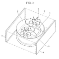
Fig. 3 is a perspective view illustrating an impeller covering process in the heat treatment method of the impeller according to the first embodiment of the present invention. -
Fig. 4 is a side view illustrating the impeller covering process in the heat treatment method of the impeller according to the first embodiment of the present invention. -
Fig. 5 is a side view analyzing a flow state of a nitrogen gas in a cooling process if the impeller covering process is not performed in the heat treatment method of the impeller according to the first embodiment of the present invention. -
Fig. 6 is a side view illustrating a different heat uniformizing jig in the impeller covering process in the heat treatment method of the impeller according to the first embodiment of the present invention. -
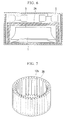
Fig. 7 is a perspective view illustrating a different heat uniformizing jig in the impeller covering process in the heat treatment method of the impeller according to the first embodiment of the present invention. -
Fig. 8 is a process flowchart illustrating a heat treatment method of an impeller according to a second embodiment of the present invention. -
Fig. 9 is a side view illustrating a first insertion process and a second insertion process in the heat treatment method of the impeller according to the second embodiment of the present invention. - Hereinafter, a heat treatment method of an
impeller 1 as a disc-shaped treatment target material according to a first embodiment of the present invention will be described. - As shown in
Fig. 1 , theimpeller 1, which is heat treated by the present embodiment, is used for a rotary machine such as a compressor for increasing pressure of a fluid. - In addition, the
impeller 1 includes adisc 1a, acover 1b, andblades 1c, which are formed integrally with each other on the basis of an axis line P. - The
disc 1a is a member having a substantial disc shape. Thedisc 1a has a small diameter end face toward one side in the direction of the axis line P and a large diameter end face toward the other side in the direction of the axis line P. These two end faces are connected to each other by a curved surface having a diameter which is gradually increased from one end side to the other end side. - The
blades 1c are provided in a plural number at regular intervals in the circumferential direction so as to rise from the curved surface in thedisc 1a. - In addition, each of the blades I c extends from the inside to the outside in the radial direction of the
disc 1a to be curved toward one direction of the circumferential direction - The
cover 1b is a member which is formed integrally with the plurality ofblades 1c so as to cover theblades 1c from one side in the direction of the axis line P. In addition, thecover 1b has a substantial disc shape when viewed from the direction of the axis line P on the basis of the axis line P. In more detail, thecover 1b has an umbrella shape having a diameter which is gradually decreased toward one side in the direction of the axis line P. The inside in the radial direction of thecover 1b has a cylindrical shape rising toward one side in the direction of the axis line P. - In addition, a region interposed between two
blades 1c adjacent to thedisc 1a and thecover 1b formspassages 10 in which a fluid flows. Moreover, the inside in the radial direction of each of thepassages 10 rises toward one side of the axis line P so that anintroduction port 1d into which the fluid is introduced in the direction of the axis line P is opened in a region interposed between thecover 1 b and thedisc 1a. - Furthermore, the
impeller 1 is provided, at a center thereof, with anaxial hole 11 penetrated in the direction of the axis line P such that a rotor (a rotary shaft), which is not shown, is fixedly inserted from the direction of the axis line P to theaxial hole 11 so as to integrally rotate theimpeller 1 and the rotor. - Next, a procedure for the heat treatment method of the
impeller 1 will be described. - As shown in
Figs. 2 to 4 , the heat treatment method of theimpeller 1 includes a heat treatment preparation process S1 of arranging theimpeller 1 before the heat treatment within avacuum furnace 3 as a heating furnace, an impeller covering process (a treatment target material covering process) S2 of covering theimpeller 1 with a heat uniformizing jig (a covering body) 2 in thevacuum furnace 3, and a heat treatment process S3 of heating or cooling theimpeller 1 from the periphery in a state in which theimpeller 1 is covered with theheat uniformizing jig 2. - First, the heat treatment preparation process S1 is performed. That is, the impeller before the heat treatment, which is manufactured by forging and the like, is arranged and prepared in the
vacuum furnace 3. - Here, the
vacuum furnace 3 is a type of heat treatment furnace which may suppress an oxidation reaction during the heat treatment by maintaining an inner portion of the furnace at a pressure lower than atmospheric pressure. In addition, two stirringfans 5 for stirring an atmosphere fluid in thevacuum furnace 3 are provided at an interval on an upper surface of the inner portion of thevacuum furnace 3, andheaters 4 are wholly provided only on two facing surfaces (two surfaces located in the left and right directions inFig. 4 ) out of the four surfaces of afurnace sidewall 3a within thevacuum furnace 3. - Next, the impeller covering process S2 is performed. That is, the
impeller 1 arranged within thevacuum furnace 3 is covered by theheat uniformizing jig 2 from the circumferential direction and the direction of the axis line P within thevacuum furnace 3. Theheat uniformizing jig 2 may cover theimpeller 1 while spaced apart from theimpeller 1 or in contact with theimpeller 1. However, a method of transferring heat from theheat uniformizing jig 2 to theimpeller 1 differs between a spaced part and a contact part. Accordingly, it is preferable to cover theimpeller 1 in the spaced state when possible and the contact part is preferably disposed to be rotationally symmetric. - Here, the
heat uniformizing jig 2 is a member which is made of a radiation conversion material having high emissivity. Theheat uniformizing jig 2 has aperipheral wall portion 12 having a cylindrical shape centered on the axis line P, and anupper bottom surface 13 and alower bottom surface 14 which close upper and lower openings on theperipheral wall portion 12 from the direction of the axis line P, so as to cover theentire impeller 1. The emissivity is preferably 80% or more. - In addition, a silica sintered body, a sintered metal, or a high radiation cloth (Sourcil blanc (registered trademark), etc.) is used, for example, as the radiation conversion material. When the high radiation cloth is adopted, it is preferable in terms of costs.
- Moreover, the radiation conversion material also has permeability and it is preferable that porosity as an index of the permeability be about 50 to 90%.
- Next, the heat treatment process S3 is performed. The heat treatment process S3 includes a heating process S3a and a cooling process S3b performed after the heating process S3a.
- In the heating process S3a, the inner portion of the
vacuum furnace 3 is heated to a predetermined temperature by theheaters 4 and quenching is performed on theimpeller 1. - The predetermined temperature in the heating process S3a is determined according to the material of the
impeller 1 and the purpose of the heat treatment. For example, the temperature in the quenching treatment of the impeller made of SNCM is 820 to 900°C. - In addition, after the
impeller 1 is increased to the predetermined temperature in the heating process S3a and is maintained for a predetermined time, the cooling process S3b cools theimpeller 1 to a predetermined temperature in consideration of a change of a required material structure, thereby achieving a required hardness and yield strength. In this case, there is also a case in which nitrogen gas (a fluid) G is blown into thevacuum furnace 3 from the bottom or top thereof, and quenching is performed so that theimpeller 1 is cooled to a predetermined temperature in consideration of a change of a required material structure, thereby achieving a required hardness and yield strength. - The predetermined temperature in the cooling process S3b is determined according to the material of the
impeller 1 and the purpose of the heat treatment. For example, the temperature in the tempering treatment of the impeller made of SNCM is 580 to 630°C. - In the heat treatment method of the
impeller 1, the heating process S3a of the heat treatment process S3 is performed in a state in which theentire impeller 1 is covered from the circumferential direction and the direction of the axis line P by theheat uniformizing jig 2 using the radiation conversion material in the impeller covering process S2. That is, when the inner portion of thevacuum furnace 3 is heated by theheaters 4, heat from theheaters 4 primarily heats theheat uniformizing jig 2 instead of being directly transferred to theimpeller 1. - Here, since the
heat uniformizing jig 2 is made of the radiation conversion material, theheat uniformizing jig 2 may uniformly transfer heat transferred from theheaters 4 to the impeller I from the circumferential direction and the direction of the axis line P as radiant heat having high thermal emissivity. In more detail, theheat uniformizing jig 2 simply blocks heat from theheaters 4, and primarily, heat that is unevenly transferred to theheat uniformizing jig 2 in the circumferential direction by radiation and convection uniformly heats the entireheat uniformizing jig 2 by heat conduction within theheat uniformizing jig 2. Since theheat uniformizing jig 2 is made of the radiation conversion material, theheat uniformizing jig 2, which is uniformly heated by the heat conduction, may uniformly radiate heat to theimpeller 1 by radiant heat transfer. Therefore, it may be possible to prevent a required time for the heat treatment from lengthening, to prevent only parts of theimpeller 1 close to theheaters 4 from being easily heated, and to prevent a degree of heating from differing. As a result, the quenching may be uniformly performed. - In the present embodiment, since the
impeller 1 is arranged on thelower bottom surface 14 of theheat uniformizing jig 2, heating of theimpeller 1 from the downward side thereof is mainly performed by heat conduction from thelower bottom surface 14. Even in this case, since theimpeller 1 comes into contact with thelower bottom surface 14 at a part which is rotationally symmetric to the axis line P of the impeller, the degree of heating is not different. - In addition, as shown in an analyzed result of
Fig. 5 , it may be identified that, in the conventional method, when the nitrogen gas G is blown from the bottom in the cooling process S3b, a flow distribution of the nitrogen gas G is not uniform. That is, after the nitrogen gas G comes into contact with thedisc 1a at the lower portion of theimpeller 1, the nitrogen gas G flows to be dispersed outward in the radial direction of theimpeller 1. - Similarly to the heating process S3a, in the cooling process S3b of the present embodiment, the
impeller 1 may be uniformly cooled using radiant heat transfer by covering theimpeller 1 with theheat uniformizing jig 2. Moreover, theheat uniformizing jig 2 has permeability. Therefore, when the nitrogen gas G is blown in the cooling process S3b, it may be possible to suppress the nitrogen gas G from stagnating between theheat uniformizing jig 2 and theimpeller 1. Accordingly, it may be possible to reduce the time for the heat treatment process S3 by effectively improving convection heat transfer. In addition, although not shown, an analysis in a state in which theheat uniformizing jig 2 is provided is also performed by setting the permeability of theheat uniformizing jig 2 to have porosity of 80%. Consequently, a preferable result is obtained. - Since the heat treatment method of the
impeller 1 of the present embodiment uses the radiant heat transfer by theheat uniformizing jig 2, it may be possible to achieve uniform heating and uniform cooling in the heat treatment process S3. Accordingly, there is no need to perform the heat treatment in a state in which the extra thickness is provided in theimpeller 1 as in the related art. Thus, it may also be possible to reduce working man-hours of the extra thickness and reduce material costs by a reduction of the extra thickness. In addition, since theheat uniformizing jig 2 formed of the radiation conversion material having high emissivity is disposed to surround theimpeller 1, heating efficiency may be improved. Therefore, since a required time for the heat treatment process may be prevented from becoming longer and a time for the cooling process S3b may be reduced, an overall required time for the heat treatment process S3 may be reduced. - As shown in
Fig. 6 , a plurality of heat uniformizing jigs 2Amay also be stacked and disposed in the circumferential direction and the direction of the axis line P. Uniform heating and uniform cooling may be more securely achieved by properly changing a thickness of theheat uniformizing jig 2 to adjust a radiant heat quantity and permeability corresponding to the dimensions and shape of theimpeller 1. - As shown in
Fig. 7 , aheat uniformizing jig 2B may also have a plurality ofconvex portions 12b protruding toward an inner peripheral side from an inner peripheral surface of theperipheral wall portion 12. In this case, it may be possible to increase a heat transfer area inside theheat uniformizing jig 2 and to effectively improve radiant heat transfer. - Next, a heat treatment method of an
impeller 1 according to a second embodiment of the present invention will be described. - Like reference numerals refer to the same elements as those of the first embodiment and no detailed description thereof will be given.
- As shown in
Fig. 8 , the heat treatment method of the present embodiment differs from that of the first embodiment in that the heat treatment method of the present embodiment further includes a first insertion process S10 and a second insertion process S11 after the impeller covering process S2. - As shown in
Fig. 9 , the firstinsertion process S 10 is performed before the heat treatment process S3. That is, an axial hole insertion jig (an axial hole insertion body) 21, which is made of the cylinder-shaped radiation conversion material corresponding to the shape of theaxial hole 11, is inserted into theaxial hole 11 of theimpeller 1. The axialhole insertion jig 21 may also be maintained within thepassage 10 so as to be hung from the upward side or may also be maintained in contact with theaxial hole 11, in the inner portion of thevacuum furnace 3. - Furthermore, the second insertion process S11 is performed after the first insertion process S10. That is, a passage insertion jig (a passage insertion body) 20, which is made of the radiation conversion material corresponding to the shape of the
passage 10, is inserted into eachpassage 10 of theimpeller 1. Similarly to the axialhole insertion jig 21, thepassage insertion jig 20 may also be maintained within thepassage 10 so as to be hung from the upward side or may also be maintained in thepassage 10 by coming in contact therewith, in the inner portion of thevacuum furnace 3. - In this case, a method of inserting the
passage insertion jig 20 and the axialhole insertion jig 21 between theaxial hole 11 and the axialhole insertion jig 21 and between thepassage 10 and thepassage insertion jig 20 in a state in which clearances are formed therebetween may improve fluidity of the nitrogen gas in the cooling process S3b and more effectively improve convection heat transfer. - In accordance with the heat treatment method of the
impeller 1, the heat treatment process S3 is performed in a state in which thepassage insertion jig 20 and the axialhole insertion jig 21 are respectively inserted into thepassage 10 and theaxial hole 11 by the first and second insertion processes S10 and S11. For this reason, the radiant heat may be securely transferred to thepassage 10 and theaxial hole 11 since heat does not easily spread out, and uniform heating and uniform cooling of theimpeller 1 may be further achieved in the heat treatment process S3. Consequently, quenching and tempering may be uniformly achieved. - In addition, since each of the axial
hole insertion jig 21 and thepassage insertion jig 20 is made of the radiation conversion material and has permeability, the nitrogen gas G may spread to thepassage 10 and theaxial hole 11. Therefore, it may be possible to reduce a required time for the cooling process S3b by an increase of convection heat transfer. - Since the heat treatment method of the
impeller 1 according to the present embodiment may further achieve uniform heating and uniform cooling in the heat treatment process S3 by means of the axialhole insertion jig 21 and thepassage insertion jig 20 in addition to theheat uniformizing jig 2, it may be possible to reduce the extra thickness of the impeller. In addition, it may be possible to reduce the time for the heat treatment in the cooling process S3b and to further reduce an overall required time for the heat treatment process S3. - Both of the first and second insertion processes S10 and S11 need not necessarily be performed, and need not be performed sequentially.
- In addition, as in the
heat uniformizing jig 2B shown inFig. 7 , the axialhole insertion jig 21 and thepassage insertion jig 20 may also each form, for example, convex portions on the outer peripheral surfaces thereof so as to increase a heat transfer area. In this case, the radiant heat transfer effect may be improved and thus the uniform heating and the uniform cooling may be further achieved in the heat treatment process S3. - Although the embodiments of the present invention have been described in detail, a few design modifications may be made in these embodiments without departing from the principles and scope of the invention.
- For example, although the above-mentioned embodiments describe that the heat uniformizing jig has the
peripheral wall portion 12, theupper bottom surface 13, and thelower bottom surface 14 so as to cover theentire impeller 1, the heat uniformizing jig, for example, may also be configured by only theperipheral wall portion 12. - In addition, although the embodiments of the present invention illustrate the
impeller 1 as a heat treatment object, the present invention may be similarly applied to heat treatments other than that of theimpeller 1. Furthermore, the present invention may be similarly applied to heat treatments other than the quenching and tempering described in the above-mentioned embodiments. For example, the heat treatments may include a solution heat treatment, an aging heat treatment, etc. - In addition, the
vacuum furnace 3 is not limited to the above-mentioned embodiments. For example, a case in which two or morestirring fans 5 are installed, a case in which no stirringfan 5 is installed, and a case in which the installation surfaces of theheaters 5 and the number of installation surfaces are different from each other may be similarly applied to the embodiments. - In addition, although the embodiments of the present invention describe, for example, the closed type impeller having the
cover 1b as a heat treatment object, the present invention may be similarly applied to an open type impeller not having thecover 1b. - In addition, although the embodiments of the present invention describe a case of using the
vacuum furnace 3 as a heating furnace, the present invention is not limited thereto. For example, any one of an atmosphere furnace having an inner pressure equal to atmospheric pressure and a press furnace having a pressure higher than atmospheric pressure may also be similarly applied to the embodiments. In this case, a reducing gas is preferably used as the atmosphere gas in order to maximally suppress the oxidation reaction during the heat treatment. - According to the above heat treatment method, extra thickness may be reduced while realizing heat uniformizing in a heat treatment process and preventing a heat treatment time from lengthening, by performing a treatment target material covering process using a covering body made of a radiation conversion material.
-
- 1
- Impeller (treatment target material)
- 1a
- Disc
- 1b
- Cover
- 1c
- Blade
- 1d
- Introduction port
- 2
- Heat uniformizing jig (covering body)
- 2A, 2B
- Heat uniformizing jig
- 3
- Vacuum furnace
- 3a
- Furnace sidewall
- 4
- Heater
- 5
- Stirring fan
- 10
- Passage
- 11
- Axial hole
- 12
- Peripheral wall portion
- 12b
- Convex portion
- 13
- Upper bottom surface
- 14
- Lower bottom surface
-
S 1 - Heat treatment preparation process
- S2
- Impeller covering process (treatment target material covering process)
- S3
- Heat treatment process
- S3a
- Heating process
- S3b
- Cooling process
- P
- Axis line
- G
- Nitrogen gas (fluid)
- S10
- First insertion process
- 20
- Passage insertion jig
- S1
- Second insertion process
- 21
- Axial hole insertion jig
Claims (5)
- A heat treatment method of a disc-shaped treatment target material, the heat treatment method comprising:a treatment target material covering process of covering an outer peripheral surface of the treatment target material in a circumferential direction with a covering body made of a radiation conversion material which radiates transferred heat as radiant heat; anda heat treatment process of performing heat treatment by heating or cooling the treatment target material covered with the covering body from the periphery.
- The heat treatment method according to claim 1, wherein:in the treatment target material covering process, a member made of the radiation conversion material having permeability is used as the covering body; andin the heat treatment process, a fluid in a heat treatment atmosphere flows from the outside of the covering body to the treatment target material due to permeability of the covering body.
- The heat treatment method according to claim 2, wherein, in the treatment target material covering process, the treatment target material is also covered from an axial direction by the covering body.
- The heat treatment method according to any one of claims 1 to 3, wherein:the treatment target material is an impeller having an axial hole into which a rotary shaft is capable of being inserted;the heat treatment method further comprises a first insertion process of inserting an axial hole insertion body made of the radiation conversion material into the axial hole; andthe heat treatment process is performed in a state in which the axial hole insertion body is inserted into the axial hole.
- The heat treatment method according to any one of claims 1 to 4, wherein:the treatment target material is an impeller having a passage therein;the heat treatment method further comprises a second insertion process of inserting a passage insertion body made of the radiation conversion material into the passage; andthe heat treatment process is performed in a state in which the passage insertion body is inserted into the passage.
Applications Claiming Priority (2)
| Application Number | Priority Date | Filing Date | Title |
|---|---|---|---|
| JP2012033135A JP5863499B2 (en) | 2012-02-17 | 2012-02-17 | Heat treatment method |
| PCT/JP2013/053673 WO2013122192A1 (en) | 2012-02-17 | 2013-02-15 | Heat treatment method |
Publications (2)
| Publication Number | Publication Date |
|---|---|
| EP2816126A1 true EP2816126A1 (en) | 2014-12-24 |
| EP2816126A4 EP2816126A4 (en) | 2015-10-21 |
Family
ID=48984301
Family Applications (1)
| Application Number | Title | Priority Date | Filing Date |
|---|---|---|---|
| EP13748875.5A Withdrawn EP2816126A4 (en) | 2012-02-17 | 2013-02-15 | Heat treatment method |
Country Status (5)
| Country | Link |
|---|---|
| US (1) | US9423183B2 (en) |
| EP (1) | EP2816126A4 (en) |
| JP (1) | JP5863499B2 (en) |
| CN (1) | CN104093864B (en) |
| WO (1) | WO2013122192A1 (en) |
Families Citing this family (5)
| Publication number | Priority date | Publication date | Assignee | Title |
|---|---|---|---|---|
| CN105936973B (en) * | 2016-07-08 | 2017-08-08 | 天津华源线材制品有限公司 | A kind of iron wire heats guiding device |
| US11781198B2 (en) * | 2016-12-07 | 2023-10-10 | Ebner Industrieofenbau Gmbh | Temperature control device for the temperature control of a component |
| JP7105656B2 (en) * | 2018-09-10 | 2022-07-25 | 株式会社ジェイテクトサーモシステム | Heat treatment apparatus and heat treatment method |
| CN110004278B (en) * | 2019-04-12 | 2021-03-02 | 沈阳透平机械股份有限公司 | A preparatory heat treatment process of FV520(B) steel for ternary milling and welding impeller |
| JP2021091960A (en) * | 2019-12-09 | 2021-06-17 | 中外炉工業株式会社 | Heat treatment device |
Family Cites Families (17)
| Publication number | Priority date | Publication date | Assignee | Title |
|---|---|---|---|---|
| DD82746A (en) | ||||
| US1975422A (en) * | 1931-12-07 | 1934-10-02 | Hellenbroich Wilhelm Josef | Method and apparatus for the manufacture of disk ribbed pipes |
| JPS5819443A (en) * | 1981-07-25 | 1983-02-04 | Daido Steel Co Ltd | heat treatment furnace |
| US4570053A (en) * | 1983-05-04 | 1986-02-11 | General Electric Company | Apparatus for heating a turbine wheel |
| JPS61110717A (en) * | 1984-11-05 | 1986-05-29 | Mitsubishi Heavy Ind Ltd | Manufacture of impeller for refrigerator |
| US4596526A (en) * | 1985-03-04 | 1986-06-24 | Worthington Industries, Inc. | Batch coil annealing furnace and method |
| JPH03193816A (en) | 1989-12-22 | 1991-08-23 | Daido Steel Co Ltd | Heat treatment furnace |
| JP3047504B2 (en) | 1991-04-25 | 2000-05-29 | 石川島播磨重工業株式会社 | Heat treatment method for turbine disk |
| JPH0618015A (en) | 1992-06-30 | 1994-01-25 | Mitsubishi Heavy Ind Ltd | Radiation transducer for incinerator |
| JPH06145781A (en) | 1992-11-02 | 1994-05-27 | Nippon Techno:Kk | Atmosphere heat treatment furnace |
| JP2842767B2 (en) * | 1993-09-22 | 1999-01-06 | 石川島播磨重工業株式会社 | Heat treatment furnace for round steel coil |
| JP3882258B2 (en) | 1997-04-11 | 2007-02-14 | 旭硝子株式会社 | heating furnace |
| US5934871A (en) * | 1997-07-24 | 1999-08-10 | Murphy; Donald G. | Method and apparatus for supplying a anti-oxidizing gas to and simultaneously cooling a shaft and a fan in a heat treatment chamber |
| JP2000018192A (en) | 1998-07-03 | 2000-01-18 | Hitachi Ltd | Centrifugal impeller |
| ITMI20021876A1 (en) | 2002-09-03 | 2004-03-04 | Nuovo Pignone Spa | IMPROVED PROCEDURE FOR MAKING A ROTOR OF ONE |
| JP2009156122A (en) | 2007-12-26 | 2009-07-16 | Mitsubishi Heavy Ind Ltd | Impeller for centrifugal compressor |
| US7874835B2 (en) * | 2008-03-27 | 2011-01-25 | Schwank Ltd. | Radiant tube heater and burner assembly for use therein |
-
2012
- 2012-02-17 JP JP2012033135A patent/JP5863499B2/en not_active Expired - Fee Related
-
2013
- 2013-02-15 US US14/378,360 patent/US9423183B2/en not_active Expired - Fee Related
- 2013-02-15 WO PCT/JP2013/053673 patent/WO2013122192A1/en not_active Ceased
- 2013-02-15 EP EP13748875.5A patent/EP2816126A4/en not_active Withdrawn
- 2013-02-15 CN CN201380007999.6A patent/CN104093864B/en not_active Expired - Fee Related
Also Published As
| Publication number | Publication date |
|---|---|
| JP5863499B2 (en) | 2016-02-16 |
| US9423183B2 (en) | 2016-08-23 |
| US20150017593A1 (en) | 2015-01-15 |
| JP2013170274A (en) | 2013-09-02 |
| WO2013122192A1 (en) | 2013-08-22 |
| EP2816126A4 (en) | 2015-10-21 |
| CN104093864A (en) | 2014-10-08 |
| CN104093864B (en) | 2016-03-16 |
Similar Documents
| Publication | Publication Date | Title |
|---|---|---|
| US9423183B2 (en) | Heat treatment method | |
| US10161404B2 (en) | Turbo-molecular pump | |
| KR101444039B1 (en) | Substrate processing apparatus and heating equipment | |
| JP4458079B2 (en) | Vacuum carburizing equipment | |
| JP2013170274A5 (en) | ||
| KR20200029360A (en) | Apparatus and method for heat treatment | |
| JP2009024243A (en) | Quenching method | |
| JP6026795B2 (en) | Rotary heat treatment furnace | |
| JP6113961B2 (en) | Heat treatment equipment | |
| JP5918881B1 (en) | Stirring fan for heat treatment apparatus and heat treatment apparatus provided with the same | |
| JP5563027B2 (en) | Stirring fan for heat treatment apparatus and heat treatment apparatus provided with the same | |
| KR101539314B1 (en) | Method for manufacturing camshaft for internal combustion engine | |
| JP2013216959A (en) | Thermal treatment equipment for ring-shaped member | |
| CN109923363B (en) | Heat treatment apparatus with non-uniform thermal insulation | |
| CN212375318U (en) | Aging furnace for aluminum profile production | |
| US9313832B2 (en) | Method and system for localized heat treating using susceptor | |
| KR101646709B1 (en) | Heat treatment jig for vacuum furnace and method for calibrating surface flatness using the same | |
| KR101521464B1 (en) | Heat treatment apparatus | |
| KR200439608Y1 (en) | Vacuum heat treatment furnace | |
| CN106574317A (en) | A tire rasp blade | |
| KR200391448Y1 (en) | Heatexchanger as one body having heat treatment furnace | |
| CN211316963U (en) | Heating furnace capable of being heated uniformly | |
| CN215799781U (en) | Heat treatment processing equipment for circular saw blade base body | |
| KR102359596B1 (en) | A seal cap and a semiconductor manufacturing equipment comprising thereof | |
| CN212741462U (en) | Rear screen cooling port structure of vacuum heat treatment furnace |
Legal Events
| Date | Code | Title | Description |
|---|---|---|---|
| PUAI | Public reference made under article 153(3) epc to a published international application that has entered the european phase |
Free format text: ORIGINAL CODE: 0009012 |
|
| 17P | Request for examination filed |
Effective date: 20140814 |
|
| AK | Designated contracting states |
Kind code of ref document: A1 Designated state(s): AL AT BE BG CH CY CZ DE DK EE ES FI FR GB GR HR HU IE IS IT LI LT LU LV MC MK MT NL NO PL PT RO RS SE SI SK SM TR |
|
| AX | Request for extension of the european patent |
Extension state: BA ME |
|
| DAX | Request for extension of the european patent (deleted) | ||
| RA4 | Supplementary search report drawn up and despatched (corrected) |
Effective date: 20150921 |
|
| RIC1 | Information provided on ipc code assigned before grant |
Ipc: C21D 1/34 20060101ALI20150915BHEP Ipc: C21D 9/67 20060101ALI20150915BHEP Ipc: F04D 29/28 20060101ALI20150915BHEP Ipc: C21D 9/673 20060101ALI20150915BHEP Ipc: F27B 17/00 20060101ALI20150915BHEP Ipc: C21D 9/677 20060101ALI20150915BHEP Ipc: C21D 9/00 20060101AFI20150915BHEP |
|
| STAA | Information on the status of an ep patent application or granted ep patent |
Free format text: STATUS: THE APPLICATION HAS BEEN WITHDRAWN |
|
| 18W | Application withdrawn |
Effective date: 20170922 |