EP2815902B2 - Suspension system for a self-propelled harvesting machine with tracks - Google Patents
Suspension system for a self-propelled harvesting machine with tracks Download PDFInfo
- Publication number
- EP2815902B2 EP2815902B2 EP14002082.7A EP14002082A EP2815902B2 EP 2815902 B2 EP2815902 B2 EP 2815902B2 EP 14002082 A EP14002082 A EP 14002082A EP 2815902 B2 EP2815902 B2 EP 2815902B2
- Authority
- EP
- European Patent Office
- Prior art keywords
- self
- cylinder
- harvesting machine
- suspension system
- propelled harvesting
- Prior art date
- Legal status (The legal status is an assumption and is not a legal conclusion. Google has not performed a legal analysis and makes no representation as to the accuracy of the status listed.)
- Not-in-force
Links
Images


Classifications
-
- B—PERFORMING OPERATIONS; TRANSPORTING
- B60—VEHICLES IN GENERAL
- B60G—VEHICLE SUSPENSION ARRANGEMENTS
- B60G13/00—Resilient suspensions characterised by arrangement, location or type of vibration dampers
- B60G13/001—Arrangements for attachment of dampers
- B60G13/005—Arrangements for attachment of dampers characterised by the mounting on the axle or suspension arm of the damper unit
-
- B—PERFORMING OPERATIONS; TRANSPORTING
- B60—VEHICLES IN GENERAL
- B60G—VEHICLE SUSPENSION ARRANGEMENTS
- B60G2204/00—Indexing codes related to suspensions per se or to auxiliary parts
- B60G2204/10—Mounting of suspension elements
- B60G2204/12—Mounting of springs or dampers
- B60G2204/128—Damper mount on vehicle body or chassis
-
- B—PERFORMING OPERATIONS; TRANSPORTING
- B60—VEHICLES IN GENERAL
- B60G—VEHICLE SUSPENSION ARRANGEMENTS
- B60G2204/00—Indexing codes related to suspensions per se or to auxiliary parts
- B60G2204/10—Mounting of suspension elements
- B60G2204/12—Mounting of springs or dampers
- B60G2204/129—Damper mount on wheel suspension or knuckle
-
- B—PERFORMING OPERATIONS; TRANSPORTING
- B60—VEHICLES IN GENERAL
- B60G—VEHICLE SUSPENSION ARRANGEMENTS
- B60G2300/00—Indexing codes relating to the type of vehicle
- B60G2300/32—Track vehicles
Definitions
- the invention relates to self-propelled harvesting machines and particularly to the provision of suspension for ground engaging tracks.
- Self-propelled harvesting machines include by way of example combine harvesters, forage harvesters, and sugar-cane harvesters. Over many years the size and weight of machines has increased significantly driven by a demand for greater processing capacity. Offsetting this demand for larger machines, there is a growing awareness of the damage and problems caused by high ground pressures exerted by the footprint of the machines upon the fields. For example, soil compaction can increase runoff of rainfall, in turn resulting in irreversible erosion. Moreover, the risk of getting stuck in wet field conditions is increased for machines with higher ground pressures.
- US-8,341,926 discloses a self-propelled harvesting machine having a crawler track assembly provided with a damping system. The mechanism by which the track assembly is mounted to the axle is not disclosed.
- US-2007/0017714 discloses a track assembly for a variety of all terrain vehicles, the assembly including idler wheel suspension for the track.
- a self-propelled harvesting machine comprising a suspension system and a crawler track assembly according to the pre-characterising portion of claim 1 is described in European patent application EP 1 018 294 A1 .
- a self-propelled harvesting machine comprising a suspension system and a crawler track assembly as recited in claim 1 of the attached claims.
- the track assembly typically comprises an endless ground-engaging belt wrapped around a plurality of wheels, at least one of which is a propulsion wheel driven by an external driving torque and at least two of which are idler wheels.
- the track assembly may also comprises a bogie truck upon which the propulsion wheel and idler wheels are supported to maintain a spatial relationship between those wheels.
- the propulsion wheel is preferably mounted directly onto the attachment hub of the suspension system.
- the damper comprises a fluid-filled cylinder which can be conveniently connected between the chassis and the final drive by appropriate attachment means.
- the fluid may be compressed air, but more preferably hydraulic fluid.
- the accumulator is preferably a nitrogen charged accumulator.
- the parallel-connected accumulators charged with different pressures provide a multi-mode damping function to the vehicle to cater for different operating conditions, for example a transport (unloaded) condition and an operating (loaded) condition.
- the control circuit preferably comprises a check valve connected in parallel with a throttle valve between the cylinder and the accumulator (or accumulators).
- the throttle valve provides a damping effect in one direction of cylinder travel whilst the check valve permits the cylinder to return to the rest position rapidly.
- the hydraulic control circuit may be a closed circuit or an open circuit, the latter including a pump/drain means to adjust the resting position of the cylinder piston.
- the cylinder may be dual-acting or single-acting, wherein the former permits a more accurate control of the cylinder action and is preferred for some final drive geometries.
- a combine harvester 10 comprises a cab 12, elevator housing 13, unloading auger 14, left and right track units 16,18, and steerable rear wheels 20 (only one of which is shown).
- a header for cutting and gathering a standing crop as the machine is advanced across a field, can be attached to the front of elevator housing 13 in a known manner.
- the header is not shown in the drawings provided.
- each track assembly 16,18 comprises an endless ground-engaging belt 17a wrapped around a propulsion (or driving) wheel 17b and four idler wheels 17c-17f.
- the wheels 17b-17f are mounted on a bogie truck (or track frame) 17g which maintains a spatial relationship between the wheels.
- the idler wheels 17c-17f may be mounted to the bogie truck by independent damped suspension arms (not shown) as is known in the art, from WO-2006/018215 for example.
- a left-hand suspension system 25 and a right-hand suspension system 26 are secured at either end of a transverse frame member or axle 22 which forms part of the vehicle chassis.
- the axle 22 is shown as a rectangular box section beam but it should be understood that the axle 22 may take other forms of construction such as an I-section beam.
- Each suspension assembly 25, 26 presents an attachment hub 24 to which the propulsion wheel 17b of each respective track unit 16, 18 is secured. However, in an alternative arrangement, a ground-engaging wheel may be secured directly to the attachment hub 24.
- Left-hand suspension system 25 comprises a final drive unit which itself comprises an input shaft 28 which is drivingly connected to an engine via a gear box (not shown).
- the construction of the final drive unit is similar to that of a construction of hillside combine described in EP-0,698,338 to which reference is invited.
- the input shaft 28 extends transversely with respect to the forward direction of travel of the combine 10 and is supported for rotation by a bearing unit 30 which is secured to the axle 22 by means of a welded bracket 32. Connected to a torque source such as an engine or electric motor via a gearbox (not shown) the input shaft 28 and serves to convey a driving torque to the final drive and the track units.
- a torque source such as an engine or electric motor via a gearbox (not shown) the input shaft 28 and serves to convey a driving torque to the final drive and the track units.
- the input shaft 28 extends through the casing 34 of the final drive unit 25, the casing 34 enclosing a pair of gears (not shown), one of which is keyed to and driven by the input shaft 28.
- the second gear within the housing 34 meshes with the first gear and is keyed on to an output shaft which extends outwardly from the combine and drives the attachment hub 24.
- An outer housing 36 has a circular body which is concentric with the output shaft and attachment hub 24 and comprises an integral extension part 36a which is journalled onto the outer end of input shaft 28.
- the components 34, 36 of the final drive housing together with the attachment hub 24 are arranged to pivot around an axis defined by the input shaft 28 in a direction indicated by arrow X in Figure 5 . Movement of the final drive 25 around input shaft 28 away from a resting position is damped by damping cylinder 40 which is connected at a front end to a bracket 42 formed from two parallel plates 42a, 42b welded to the axle 24, and at a rear end to the housing 34 by a pin 44 which permits pivoting movement.
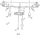
- Damping cylinder 40 forms part of a background (non-invention) configuration of hydraulic circuit 100 shown in Figure 8 together with the equivalent right-hand cylinder 40'.
- Each damping cylinder 40, 40' is dual-acting wherein one side of each piston 46, 46' is connected to a nitrogen-charged accumulator 48, 48' via a respective check valve 50, 50' and a throttle valve 52, 52'.
- the hydraulic circuit 100 comprises means to adjust the position of the pistons 46,46' in the respective cylinders and thus the resting position of the suspension.
- a pump 60 and tank 64 are connected to the cylinders 40, 40' via a solenoid-actuated three-position directional control valve 62.
- the pump 60 is driven mechanically and derives a driving torque from the engine of the harvester in a known manner.
- the directional control valve 62 controls the delivery of pressurised fluid to and from the pump 60 and tank 64 in response to electrical control signals that activate the solenoids.
- the electrical control signals may be generated automatically in response to sensed parameters or manually by the operator.
- the directional control valve 62 closes off the hydraulic connection to the pump and tank 60, 64.
- pressurised hydraulic fluid is conveyed to one side of each cylinder 40, 40' to adjust the resting position.
- the pump 60, tank 64 and valve 62 may be omitted leaving a closed circuit for each cylinder 40, 40' in which the resting position cannot be adjusted.
- the overall weight of the combine harvester when being transported is significantly less than when in operation.
- the header In a transport mode the header is detached and the grain bins are typically empty.
- the attached header and carried grain add a significant additional load to the chassis.
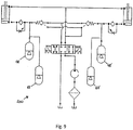
- additional accumulators 68, 68' are connected in parallel to the aforementioned accumulators 48, 48' as shown in the hydraulic circuit 200 embodying aspects of the present invention and illustrated in Figure 9 .
- each of the first pair of accumulators 48, 48' may be charged to a pressure of 120 bar whereas the second pair 68, 68' are charged to 230 bar.
- the first pair 48, 48' of accumulators provide the desired cushioning to the cylinders 40, 40'.
- the second pair of accumulators 68, 68' charged to a higher pressure, provide the desired freedom of movement.
- Additional accumulators may be provided in a similar fashion to deliver damping functionality targeted at different machine weight levels.
Landscapes
- Engineering & Computer Science (AREA)
- Mechanical Engineering (AREA)
- Vehicle Body Suspensions (AREA)
- Harvester Elements (AREA)
- Combines (AREA)
Description
- The invention relates to self-propelled harvesting machines and particularly to the provision of suspension for ground engaging tracks.
- Self-propelled harvesting machines include by way of example combine harvesters, forage harvesters, and sugar-cane harvesters. Over many years the size and weight of machines has increased significantly driven by a demand for greater processing capacity. Offsetting this demand for larger machines, there is a growing awareness of the damage and problems caused by high ground pressures exerted by the footprint of the machines upon the fields. For example, soil compaction can increase runoff of rainfall, in turn resulting in irreversible erosion. Moreover, the risk of getting stuck in wet field conditions is increased for machines with higher ground pressures.
- Reduction of the ground pressure by reducing the weight of these harvesting machines can only be exploited to a limited extent without overly affecting the machine capacity. Instead, manufacturers have resorted to increasing the machine footprint by using larger wheels and, more recently, ground engaging tracks.
- Despite the advantages offered, the ride comfort provided by tracked harvesters is noticeably inferior to equivalent machines with wheels.
US-8,341,926 discloses a self-propelled harvesting machine having a crawler track assembly provided with a damping system. The mechanism by which the track assembly is mounted to the axle is not disclosed.US-2007/0017714 discloses a track assembly for a variety of all terrain vehicles, the assembly including idler wheel suspension for the track. - There is a desire by manufacturers to find cheaper, simpler and more robust suspension systems for tracked harvesting machines.
- Therefore, it is one object of the invention to provide an improved suspension system for a self-propelled harvesting machine which can be employed for track assemblies. A self-propelled harvesting machine comprising a suspension system and a crawler track assembly according to the pre-characterising portion of claim 1 is described in
European patent application EP 1 018 294 A1 . - In accordance with the invention there is provided a self-propelled harvesting machine comprising a suspension system and a crawler track assembly as recited in claim 1 of the attached claims.
- By providing a final drive unit which pivots around an input shaft a vertical degree of freedom is provided for the crawler track assembly in a compact and robust construction. Furthermore, the damper simply cushions the rotational movement of the final drive relative to the chassis.
- The track assembly typically comprises an endless ground-engaging belt wrapped around a plurality of wheels, at least one of which is a propulsion wheel driven by an external driving torque and at least two of which are idler wheels. The track assembly may also comprises a bogie truck upon which the propulsion wheel and idler wheels are supported to maintain a spatial relationship between those wheels. The propulsion wheel is preferably mounted directly onto the attachment hub of the suspension system. The provision of a damper between the chassis and the final drive in accordance with the invention results in damping of the entire track assembly relative to the vehicle chassis.
- The damper comprises a fluid-filled cylinder which can be conveniently connected between the chassis and the final drive by appropriate attachment means. The fluid may be compressed air, but more preferably hydraulic fluid.
- The accumulator is preferably a nitrogen charged accumulator. The parallel-connected accumulators charged with different pressures provide a multi-mode damping function to the vehicle to cater for different operating conditions, for example a transport (unloaded) condition and an operating (loaded) condition.
- The control circuit preferably comprises a check valve connected in parallel with a throttle valve between the cylinder and the accumulator (or accumulators). The throttle valve provides a damping effect in one direction of cylinder travel whilst the check valve permits the cylinder to return to the rest position rapidly.
- The hydraulic control circuit may be a closed circuit or an open circuit, the latter including a pump/drain means to adjust the resting position of the cylinder piston. The cylinder may be dual-acting or single-acting, wherein the former permits a more accurate control of the cylinder action and is preferred for some final drive geometries.
- Further advantages of the invention will become apparent from reading the following description of specific embodiments with reference to the appended drawings in which:
-
Figure 1 is an upper front left perspective view of a combine harvester fitted with a pair of track suspension systems in accordance with the invention, the body of the combine shown in ghost form; -
Figure 2 is an upper front left perspective view of the front axle, suspension systems and associated track units of the combine harvester ofFigure 1 ; -
Figure 3 is an upper front left perspective view of the front axle and suspension systems ofFigure 2 shown with the track units removed; -
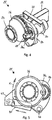
Figure 4 is an upper left rear perspective view of the left-hand suspension system ofFigure 2 ; -
Figure 5 is a left side elevation of the left-hand suspension system ofFigure 2 ; -
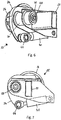
Figure 6 is a right rear perspective view of the left-hand suspension system ofFigure 2 ; -
Figure 7 is right hand view from the section VII-VII ofFigure 3 ; -
Figure 8 shows, for illustrative purposes only, and outside the scope of the present invention, a hydraulic circuit for controlling the suspension systems such as those illustrated inFigures 1 to 7 ; and, -
Figure 9 shows a hydraulic circuit for controlling the suspension systems illustrated inFigures 1 to 7 in a system according to the present invention. - With reference to
Figure 1 a combine harvester 10 comprises acab 12, elevator housing 13, unloadingauger 14, left andright track units - Although explained in relation to a combine harvester, it should be understood that the suspension system described hereinafter can be adopted on other self propelled harvesting machines without significant effort including forage harvesters and sugar cane for example.
- With reference to
Figure 2 , eachtrack assembly engaging belt 17a wrapped around a propulsion (or driving) wheel 17b and four idler wheels 17c-17f. The wheels 17b-17f are mounted on a bogie truck (or track frame) 17g which maintains a spatial relationship between the wheels. The idler wheels 17c-17f may be mounted to the bogie truck by independent damped suspension arms (not shown) as is known in the art, fromWO-2006/018215 for example. - Turning to
Figures 2 to 7 , a left-hand suspension system 25 and a right-hand suspension system 26 are secured at either end of a transverse frame member oraxle 22 which forms part of the vehicle chassis. Theaxle 22 is shown as a rectangular box section beam but it should be understood that theaxle 22 may take other forms of construction such as an I-section beam. Eachsuspension assembly attachment hub 24 to which the propulsion wheel 17b of eachrespective track unit attachment hub 24. - For sake of simple explanation, only the left-
hand suspension assembly 25 will be described hereinafter. However, it should be understood that the construction of the right-hand suspension assembly 26 is effectively a mirror image of that described. - Left-
hand suspension system 25 comprises a final drive unit which itself comprises aninput shaft 28 which is drivingly connected to an engine via a gear box (not shown). The construction of the final drive unit is similar to that of a construction of hillside combine described inEP-0,698,338 to which reference is invited. - The
input shaft 28 extends transversely with respect to the forward direction of travel of the combine 10 and is supported for rotation by abearing unit 30 which is secured to theaxle 22 by means of awelded bracket 32. Connected to a torque source such as an engine or electric motor via a gearbox (not shown) theinput shaft 28 and serves to convey a driving torque to the final drive and the track units. - The
input shaft 28 extends through thecasing 34 of thefinal drive unit 25, thecasing 34 enclosing a pair of gears (not shown), one of which is keyed to and driven by theinput shaft 28. The second gear within thehousing 34 meshes with the first gear and is keyed on to an output shaft which extends outwardly from the combine and drives theattachment hub 24. Anouter housing 36 has a circular body which is concentric with the output shaft andattachment hub 24 and comprises anintegral extension part 36a which is journalled onto the outer end ofinput shaft 28. - The
components attachment hub 24 are arranged to pivot around an axis defined by theinput shaft 28 in a direction indicated by arrow X inFigure 5 . Movement of thefinal drive 25 aroundinput shaft 28 away from a resting position is damped by dampingcylinder 40 which is connected at a front end to a bracket 42 formed from two parallel plates 42a, 42b welded to theaxle 24, and at a rear end to thehousing 34 by apin 44 which permits pivoting movement. -
Damping cylinder 40 forms part of a background (non-invention) configuration ofhydraulic circuit 100 shown inFigure 8 together with the equivalent right-hand cylinder 40'. Eachdamping cylinder 40, 40' is dual-acting wherein one side of eachpiston 46, 46' is connected to a nitrogen-chargedaccumulator 48, 48' via a respective check valve 50, 50' and a throttle valve 52, 52'. - In operation, undulations in the terrain encountered will cause the ground-
engaging track units cylinders 40, 40'. Thepre-charged accumulators 48, 48' determine the stiffness in the freedom of movement of the final drives whilst the throttle valves 52, 52' damp said motion. - In addition to damping functionality, the
hydraulic circuit 100 comprises means to adjust the position of thepistons 46,46' in the respective cylinders and thus the resting position of the suspension. - A
pump 60 andtank 64 are connected to thecylinders 40, 40' via a solenoid-actuated three-positiondirectional control valve 62. Thepump 60 is driven mechanically and derives a driving torque from the engine of the harvester in a known manner. Thedirectional control valve 62 controls the delivery of pressurised fluid to and from thepump 60 andtank 64 in response to electrical control signals that activate the solenoids. The electrical control signals may be generated automatically in response to sensed parameters or manually by the operator. - When in the centre position as shown in
Figure 8 , thedirectional control valve 62 closes off the hydraulic connection to the pump andtank cylinder 40, 40' to adjust the resting position. - In a simplified embodiment, the
pump 60,tank 64 andvalve 62 may be omitted leaving a closed circuit for eachcylinder 40, 40' in which the resting position cannot be adjusted. - The overall weight of the combine harvester when being transported is significantly less than when in operation. In a transport mode the header is detached and the grain bins are typically empty. When in operation the attached header and carried grain add a significant additional load to the chassis. To accommodate the changes in machine weight,
additional accumulators 68, 68' are connected in parallel to theaforementioned accumulators 48, 48' as shown in thehydraulic circuit 200 embodying aspects of the present invention and illustrated inFigure 9 . - By way of example only, each of the first pair of
accumulators 48, 48' may be charged to a pressure of 120 bar whereas thesecond pair 68, 68' are charged to 230 bar. When the header is detached, thefirst pair 48, 48' of accumulators provide the desired cushioning to thecylinders 40, 40'. When the header is attached, the second pair ofaccumulators 68, 68', charged to a higher pressure, provide the desired freedom of movement. - Additional accumulators may be provided in a similar fashion to deliver damping functionality targeted at different machine weight levels.
- From reading the present disclosure, other modification will be apparent to persons skilled in the art. Such modifications may involve other features which are already known in the field of agricultural harvesting machines and component parts therefore and which may be used instead of or in addition to features already described herein.
Claims (6)
- A self-propelled harvesting machine (10) comprising a suspension system and a crawler track assembly, the suspension system comprising a final drive unit having an input shaft (28) drivingly connected to a drive source, and an output shaft parallel with the input shaft (28) and connected to an attachment hub (24) on which the track assembly (16, 18) is mounted, the final drive unit being pivotally mounted to a chassis (22) around an axis which is coaxial with the input shaft, the suspension system further comprising a damper (40) between the chassis and the final drive; wherein the damper (40) comprises a fluid-filled cylinder; and wherein the suspension system further comprises a hydraulic control circuit (100) which is hydraulically connected to the cylinder, the control circuit comprising an accumulator (48) which controls the damping characteristics of the damper (40); characterised in that the control circuit (100) comprises a further accumulator (68) connected in parallel to the first-mentioned accumulator, the two accumulators (48, 68) charged with different pressures.
- A self-propelled harvesting machine according to Claim 1, wherein the control circuit (100) further comprises a check valve (50) connected in parallel with a throttle valve (52) between the cylinder (40) and the accumulator (48).
- A self-propelled harvesting machine according to any one of Claims 1 or 2, wherein the control circuit is closed.
- A self-propelled harvesting machine according to any one of Claims 1 or 2, wherein the control circuit further comprises pump/drain means to adjust a resting position of a piston in the cylinder.
- A self-propelled harvesting machine according to Claim 4, wherein the cylinder is a dual-action actuator.
- A self-propelled harvesting machine according to Claim 1, wherein the cylinder is gas-charged.
Applications Claiming Priority (1)
| Application Number | Priority Date | Filing Date | Title |
|---|---|---|---|
| GBGB1311024.2A GB201311024D0 (en) | 2013-06-20 | 2013-06-20 | Suspension system for a self-propelled harvesting machine with tracks |
Publications (4)
| Publication Number | Publication Date |
|---|---|
| EP2815902A2 EP2815902A2 (en) | 2014-12-24 |
| EP2815902A3 EP2815902A3 (en) | 2015-04-15 |
| EP2815902B1 EP2815902B1 (en) | 2018-08-08 |
| EP2815902B2 true EP2815902B2 (en) | 2021-07-14 |
Family
ID=48950216
Family Applications (1)
| Application Number | Title | Priority Date | Filing Date |
|---|---|---|---|
| EP14002082.7A Not-in-force EP2815902B2 (en) | 2013-06-20 | 2014-06-17 | Suspension system for a self-propelled harvesting machine with tracks |
Country Status (2)
| Country | Link |
|---|---|
| EP (1) | EP2815902B2 (en) |
| GB (1) | GB201311024D0 (en) |
Citations (6)
| Publication number | Priority date | Publication date | Assignee | Title |
|---|---|---|---|---|
| DE4115311A1 (en) † | 1991-05-10 | 1992-11-12 | Deere & Co | SPRING SUSPENSION OF A STEERING AXLE |
| DE4138208A1 (en) † | 1991-11-21 | 1993-05-27 | Deere & Co | HYDROPNEUMATIC SPRING SUSPENSION |
| EP0958730A1 (en) † | 1998-05-13 | 1999-11-24 | CLAAS KGaA | Device for actioning and adjusting working cylinders |
| EP1018294A1 (en) † | 1999-01-07 | 2000-07-12 | Same Deutz-Fahr S.P.A. | Drive axle for vehicles |
| DE19919959A1 (en) † | 1999-04-30 | 2000-11-02 | Caterpillar Inc | Crawler running gear for self-propelled harvester vehicles has anchor plate with lateral guide and bearing journal for crawler gear connecting flange holder on machine frame, front axle |
| WO2006018215A1 (en) † | 2004-08-11 | 2006-02-23 | Harain Verwaltungsgesellschaft Mbh & Co. Kg | Traveling mechanism for agricultural machines and off-road vehicles having an endless belt-band travelling gear and a corresponding belt-band travelling gear |
Family Cites Families (4)
| Publication number | Priority date | Publication date | Assignee | Title |
|---|---|---|---|---|
| DE19705583A1 (en) * | 1997-02-14 | 1998-08-20 | Deere & Co | Harvester |
| DE10106706A1 (en) * | 2001-02-14 | 2002-09-26 | Hydac Technology Gmbh | Suspension system, in particular for a work machine |
| US7597161B2 (en) * | 2003-01-21 | 2009-10-06 | Glen Brazier | Terrain conforming track assembly |
| DE102010036756A1 (en) * | 2010-07-30 | 2012-02-02 | Claas Selbstfahrende Erntemaschinen Gmbh | Self-propelled harvester |
-
2013
- 2013-06-20 GB GBGB1311024.2A patent/GB201311024D0/en not_active Ceased
-
2014
- 2014-06-17 EP EP14002082.7A patent/EP2815902B2/en not_active Not-in-force
Patent Citations (6)
| Publication number | Priority date | Publication date | Assignee | Title |
|---|---|---|---|---|
| DE4115311A1 (en) † | 1991-05-10 | 1992-11-12 | Deere & Co | SPRING SUSPENSION OF A STEERING AXLE |
| DE4138208A1 (en) † | 1991-11-21 | 1993-05-27 | Deere & Co | HYDROPNEUMATIC SPRING SUSPENSION |
| EP0958730A1 (en) † | 1998-05-13 | 1999-11-24 | CLAAS KGaA | Device for actioning and adjusting working cylinders |
| EP1018294A1 (en) † | 1999-01-07 | 2000-07-12 | Same Deutz-Fahr S.P.A. | Drive axle for vehicles |
| DE19919959A1 (en) † | 1999-04-30 | 2000-11-02 | Caterpillar Inc | Crawler running gear for self-propelled harvester vehicles has anchor plate with lateral guide and bearing journal for crawler gear connecting flange holder on machine frame, front axle |
| WO2006018215A1 (en) † | 2004-08-11 | 2006-02-23 | Harain Verwaltungsgesellschaft Mbh & Co. Kg | Traveling mechanism for agricultural machines and off-road vehicles having an endless belt-band travelling gear and a corresponding belt-band travelling gear |
Also Published As
| Publication number | Publication date |
|---|---|
| GB201311024D0 (en) | 2013-08-07 |
| EP2815902A2 (en) | 2014-12-24 |
| EP2815902A3 (en) | 2015-04-15 |
| EP2815902B1 (en) | 2018-08-08 |
Similar Documents
| Publication | Publication Date | Title |
|---|---|---|
| US6789379B2 (en) | Method and assembly for supporting an agricultural implement | |
| US9693502B2 (en) | Active header control | |
| US8020648B2 (en) | Windrower tractor with rear wheel suspension | |
| US11800826B2 (en) | Self-propelled baling vehicle | |
| EP3457830B1 (en) | Steered caster wheel systems | |
| US5865444A (en) | Body leveling suspension including a pivoting arrangement | |
| US10485174B2 (en) | Position/height-based hydraulic suspension system and methods of using the same | |
| US6488114B1 (en) | Grain cart | |
| EP3441244B1 (en) | Self-propelled vehicles with pitch control | |
| US20100115906A1 (en) | Agricultural harvesting machine | |
| US6843046B2 (en) | Support wheel assembly for an agricultural implement on an agricultural machine | |
| SE1350564A1 (en) | Wrist-banded vehicle | |
| US6616167B2 (en) | Towed implement | |
| US20190090424A1 (en) | Swath Roller Attachment for a Swather Tractor | |
| EP2815902B2 (en) | Suspension system for a self-propelled harvesting machine with tracks | |
| EP3556579B1 (en) | Bogie for a forestry vehicle and vehicle with at least one bogie axle | |
| DE102013111426B4 (en) | Attachment for an agricultural vehicle and agricultural vehicle | |
| CA2122487C (en) | Swivelling device, wheel suspension via a swivelling device and agricultural appliance, especially a combine harvester, with a wheel bearer and chassis fitted with a swivelling device | |
| CA2852288C (en) | Rear suspension for swather tractor | |
| US9415651B2 (en) | Rear suspension for swather tractor | |
| WO2017201396A1 (en) | A modular self-propelled vehicle for supporting and operating a device |
Legal Events
| Date | Code | Title | Description |
|---|---|---|---|
| PUAI | Public reference made under article 153(3) epc to a published international application that has entered the european phase |
Free format text: ORIGINAL CODE: 0009012 |
|
| 17P | Request for examination filed |
Effective date: 20140617 |
|
| AK | Designated contracting states |
Kind code of ref document: A2 Designated state(s): AL AT BE BG CH CY CZ DE DK EE ES FI FR GB GR HR HU IE IS IT LI LT LU LV MC MK MT NL NO PL PT RO RS SE SI SK SM TR |
|
| AX | Request for extension of the european patent |
Extension state: BA ME |
|
| PUAL | Search report despatched |
Free format text: ORIGINAL CODE: 0009013 |
|
| AK | Designated contracting states |
Kind code of ref document: A3 Designated state(s): AL AT BE BG CH CY CZ DE DK EE ES FI FR GB GR HR HU IE IS IT LI LT LU LV MC MK MT NL NO PL PT RO RS SE SI SK SM TR |
|
| AX | Request for extension of the european patent |
Extension state: BA ME |
|
| RIC1 | Information provided on ipc code assigned before grant |
Ipc: B62D 55/04 20060101ALI20150310BHEP Ipc: A01D 75/28 20060101ALI20150310BHEP Ipc: A01D 67/00 20060101ALI20150310BHEP Ipc: B60G 13/00 20060101AFI20150310BHEP |
|
| R17P | Request for examination filed (corrected) |
Effective date: 20151015 |
|
| RBV | Designated contracting states (corrected) |
Designated state(s): AL AT BE BG CH CY CZ DE DK EE ES FI FR GB GR HR HU IE IS IT LI LT LU LV MC MK MT NL NO PL PT RO RS SE SI SK SM TR |
|
| GRAP | Despatch of communication of intention to grant a patent |
Free format text: ORIGINAL CODE: EPIDOSNIGR1 |
|
| STAA | Information on the status of an ep patent application or granted ep patent |
Free format text: STATUS: GRANT OF PATENT IS INTENDED |
|
| INTG | Intention to grant announced |
Effective date: 20180208 |
|
| GRAS | Grant fee paid |
Free format text: ORIGINAL CODE: EPIDOSNIGR3 |
|
| GRAA | (expected) grant |
Free format text: ORIGINAL CODE: 0009210 |
|
| STAA | Information on the status of an ep patent application or granted ep patent |
Free format text: STATUS: THE PATENT HAS BEEN GRANTED |
|
| AK | Designated contracting states |
Kind code of ref document: B1 Designated state(s): AL AT BE BG CH CY CZ DE DK EE ES FI FR GB GR HR HU IE IS IT LI LT LU LV MC MK MT NL NO PL PT RO RS SE SI SK SM TR |
|
| REG | Reference to a national code |
Ref country code: GB Ref legal event code: FG4D |
|
| REG | Reference to a national code |
Ref country code: CH Ref legal event code: EP Ref country code: AT Ref legal event code: REF Ref document number: 1026570 Country of ref document: AT Kind code of ref document: T Effective date: 20180815 |
|
| REG | Reference to a national code |
Ref country code: IE Ref legal event code: FG4D |
|
| REG | Reference to a national code |
Ref country code: DE Ref legal event code: R096 Ref document number: 602014029786 Country of ref document: DE |
|
| REG | Reference to a national code |
Ref country code: NL Ref legal event code: MP Effective date: 20180808 |
|
| REG | Reference to a national code |
Ref country code: LT Ref legal event code: MG4D |
|
| REG | Reference to a national code |
Ref country code: AT Ref legal event code: MK05 Ref document number: 1026570 Country of ref document: AT Kind code of ref document: T Effective date: 20180808 |
|
| PG25 | Lapsed in a contracting state [announced via postgrant information from national office to epo] |
Ref country code: FI Free format text: LAPSE BECAUSE OF FAILURE TO SUBMIT A TRANSLATION OF THE DESCRIPTION OR TO PAY THE FEE WITHIN THE PRESCRIBED TIME-LIMIT Effective date: 20180808 Ref country code: LT Free format text: LAPSE BECAUSE OF FAILURE TO SUBMIT A TRANSLATION OF THE DESCRIPTION OR TO PAY THE FEE WITHIN THE PRESCRIBED TIME-LIMIT Effective date: 20180808 Ref country code: IS Free format text: LAPSE BECAUSE OF FAILURE TO SUBMIT A TRANSLATION OF THE DESCRIPTION OR TO PAY THE FEE WITHIN THE PRESCRIBED TIME-LIMIT Effective date: 20181208 Ref country code: BG Free format text: LAPSE BECAUSE OF FAILURE TO SUBMIT A TRANSLATION OF THE DESCRIPTION OR TO PAY THE FEE WITHIN THE PRESCRIBED TIME-LIMIT Effective date: 20181108 Ref country code: NL Free format text: LAPSE BECAUSE OF FAILURE TO SUBMIT A TRANSLATION OF THE DESCRIPTION OR TO PAY THE FEE WITHIN THE PRESCRIBED TIME-LIMIT Effective date: 20180808 Ref country code: GR Free format text: LAPSE BECAUSE OF FAILURE TO SUBMIT A TRANSLATION OF THE DESCRIPTION OR TO PAY THE FEE WITHIN THE PRESCRIBED TIME-LIMIT Effective date: 20181109 Ref country code: NO Free format text: LAPSE BECAUSE OF FAILURE TO SUBMIT A TRANSLATION OF THE DESCRIPTION OR TO PAY THE FEE WITHIN THE PRESCRIBED TIME-LIMIT Effective date: 20181108 Ref country code: AT Free format text: LAPSE BECAUSE OF FAILURE TO SUBMIT A TRANSLATION OF THE DESCRIPTION OR TO PAY THE FEE WITHIN THE PRESCRIBED TIME-LIMIT Effective date: 20180808 Ref country code: RS Free format text: LAPSE BECAUSE OF FAILURE TO SUBMIT A TRANSLATION OF THE DESCRIPTION OR TO PAY THE FEE WITHIN THE PRESCRIBED TIME-LIMIT Effective date: 20180808 Ref country code: PL Free format text: LAPSE BECAUSE OF FAILURE TO SUBMIT A TRANSLATION OF THE DESCRIPTION OR TO PAY THE FEE WITHIN THE PRESCRIBED TIME-LIMIT Effective date: 20180808 Ref country code: SE Free format text: LAPSE BECAUSE OF FAILURE TO SUBMIT A TRANSLATION OF THE DESCRIPTION OR TO PAY THE FEE WITHIN THE PRESCRIBED TIME-LIMIT Effective date: 20180808 |
|
| PG25 | Lapsed in a contracting state [announced via postgrant information from national office to epo] |
Ref country code: LV Free format text: LAPSE BECAUSE OF FAILURE TO SUBMIT A TRANSLATION OF THE DESCRIPTION OR TO PAY THE FEE WITHIN THE PRESCRIBED TIME-LIMIT Effective date: 20180808 Ref country code: AL Free format text: LAPSE BECAUSE OF FAILURE TO SUBMIT A TRANSLATION OF THE DESCRIPTION OR TO PAY THE FEE WITHIN THE PRESCRIBED TIME-LIMIT Effective date: 20180808 Ref country code: HR Free format text: LAPSE BECAUSE OF FAILURE TO SUBMIT A TRANSLATION OF THE DESCRIPTION OR TO PAY THE FEE WITHIN THE PRESCRIBED TIME-LIMIT Effective date: 20180808 |
|
| PG25 | Lapsed in a contracting state [announced via postgrant information from national office to epo] |
Ref country code: ES Free format text: LAPSE BECAUSE OF FAILURE TO SUBMIT A TRANSLATION OF THE DESCRIPTION OR TO PAY THE FEE WITHIN THE PRESCRIBED TIME-LIMIT Effective date: 20180808 Ref country code: EE Free format text: LAPSE BECAUSE OF FAILURE TO SUBMIT A TRANSLATION OF THE DESCRIPTION OR TO PAY THE FEE WITHIN THE PRESCRIBED TIME-LIMIT Effective date: 20180808 Ref country code: CZ Free format text: LAPSE BECAUSE OF FAILURE TO SUBMIT A TRANSLATION OF THE DESCRIPTION OR TO PAY THE FEE WITHIN THE PRESCRIBED TIME-LIMIT Effective date: 20180808 Ref country code: RO Free format text: LAPSE BECAUSE OF FAILURE TO SUBMIT A TRANSLATION OF THE DESCRIPTION OR TO PAY THE FEE WITHIN THE PRESCRIBED TIME-LIMIT Effective date: 20180808 |
|
| REG | Reference to a national code |
Ref country code: DE Ref legal event code: R026 Ref document number: 602014029786 Country of ref document: DE |
|
| PLBI | Opposition filed |
Free format text: ORIGINAL CODE: 0009260 |
|
| PLAX | Notice of opposition and request to file observation + time limit sent |
Free format text: ORIGINAL CODE: EPIDOSNOBS2 |
|
| PG25 | Lapsed in a contracting state [announced via postgrant information from national office to epo] |
Ref country code: DK Free format text: LAPSE BECAUSE OF FAILURE TO SUBMIT A TRANSLATION OF THE DESCRIPTION OR TO PAY THE FEE WITHIN THE PRESCRIBED TIME-LIMIT Effective date: 20180808 Ref country code: SM Free format text: LAPSE BECAUSE OF FAILURE TO SUBMIT A TRANSLATION OF THE DESCRIPTION OR TO PAY THE FEE WITHIN THE PRESCRIBED TIME-LIMIT Effective date: 20180808 Ref country code: SK Free format text: LAPSE BECAUSE OF FAILURE TO SUBMIT A TRANSLATION OF THE DESCRIPTION OR TO PAY THE FEE WITHIN THE PRESCRIBED TIME-LIMIT Effective date: 20180808 |
|
| 26 | Opposition filed |
Opponent name: DEERE & COMPANY/JOHN DEERE GMBH & CO. KG Effective date: 20190507 |
|
| PG25 | Lapsed in a contracting state [announced via postgrant information from national office to epo] |
Ref country code: SI Free format text: LAPSE BECAUSE OF FAILURE TO SUBMIT A TRANSLATION OF THE DESCRIPTION OR TO PAY THE FEE WITHIN THE PRESCRIBED TIME-LIMIT Effective date: 20180808 |
|
| PLBB | Reply of patent proprietor to notice(s) of opposition received |
Free format text: ORIGINAL CODE: EPIDOSNOBS3 |
|
| PG25 | Lapsed in a contracting state [announced via postgrant information from national office to epo] |
Ref country code: MC Free format text: LAPSE BECAUSE OF FAILURE TO SUBMIT A TRANSLATION OF THE DESCRIPTION OR TO PAY THE FEE WITHIN THE PRESCRIBED TIME-LIMIT Effective date: 20180808 |
|
| REG | Reference to a national code |
Ref country code: CH Ref legal event code: PL |
|
| GBPC | Gb: european patent ceased through non-payment of renewal fee |
Effective date: 20190617 |
|
| REG | Reference to a national code |
Ref country code: BE Ref legal event code: MM Effective date: 20190630 |
|
| PG25 | Lapsed in a contracting state [announced via postgrant information from national office to epo] |
Ref country code: TR Free format text: LAPSE BECAUSE OF FAILURE TO SUBMIT A TRANSLATION OF THE DESCRIPTION OR TO PAY THE FEE WITHIN THE PRESCRIBED TIME-LIMIT Effective date: 20180808 |
|
| PG25 | Lapsed in a contracting state [announced via postgrant information from national office to epo] |
Ref country code: GB Free format text: LAPSE BECAUSE OF NON-PAYMENT OF DUE FEES Effective date: 20190617 Ref country code: IE Free format text: LAPSE BECAUSE OF NON-PAYMENT OF DUE FEES Effective date: 20190617 |
|
| PG25 | Lapsed in a contracting state [announced via postgrant information from national office to epo] |
Ref country code: BE Free format text: LAPSE BECAUSE OF NON-PAYMENT OF DUE FEES Effective date: 20190630 Ref country code: LU Free format text: LAPSE BECAUSE OF NON-PAYMENT OF DUE FEES Effective date: 20190617 Ref country code: CH Free format text: LAPSE BECAUSE OF NON-PAYMENT OF DUE FEES Effective date: 20190630 Ref country code: LI Free format text: LAPSE BECAUSE OF NON-PAYMENT OF DUE FEES Effective date: 20190630 |
|
| PG25 | Lapsed in a contracting state [announced via postgrant information from national office to epo] |
Ref country code: PT Free format text: LAPSE BECAUSE OF FAILURE TO SUBMIT A TRANSLATION OF THE DESCRIPTION OR TO PAY THE FEE WITHIN THE PRESCRIBED TIME-LIMIT Effective date: 20181208 |
|
| PG25 | Lapsed in a contracting state [announced via postgrant information from national office to epo] |
Ref country code: CY Free format text: LAPSE BECAUSE OF FAILURE TO SUBMIT A TRANSLATION OF THE DESCRIPTION OR TO PAY THE FEE WITHIN THE PRESCRIBED TIME-LIMIT Effective date: 20180808 |
|
| PUAH | Patent maintained in amended form |
Free format text: ORIGINAL CODE: 0009272 |
|
| STAA | Information on the status of an ep patent application or granted ep patent |
Free format text: STATUS: PATENT MAINTAINED AS AMENDED |
|
| 27A | Patent maintained in amended form |
Effective date: 20210714 |
|
| AK | Designated contracting states |
Kind code of ref document: B2 Designated state(s): AL AT BE BG CH CY CZ DE DK EE ES FI FR GB GR HR HU IE IS IT LI LT LU LV MC MK MT NL NO PL PT RO RS SE SI SK SM TR |
|
| REG | Reference to a national code |
Ref country code: DE Ref legal event code: R102 Ref document number: 602014029786 Country of ref document: DE |
|
| PG25 | Lapsed in a contracting state [announced via postgrant information from national office to epo] |
Ref country code: HU Free format text: LAPSE BECAUSE OF FAILURE TO SUBMIT A TRANSLATION OF THE DESCRIPTION OR TO PAY THE FEE WITHIN THE PRESCRIBED TIME-LIMIT; INVALID AB INITIO Effective date: 20140617 Ref country code: MT Free format text: LAPSE BECAUSE OF FAILURE TO SUBMIT A TRANSLATION OF THE DESCRIPTION OR TO PAY THE FEE WITHIN THE PRESCRIBED TIME-LIMIT Effective date: 20180808 |
|
| PGFP | Annual fee paid to national office [announced via postgrant information from national office to epo] |
Ref country code: FR Payment date: 20210622 Year of fee payment: 8 Ref country code: DE Payment date: 20210618 Year of fee payment: 8 Ref country code: IT Payment date: 20210624 Year of fee payment: 8 |
|
| PG25 | Lapsed in a contracting state [announced via postgrant information from national office to epo] |
Ref country code: MK Free format text: LAPSE BECAUSE OF FAILURE TO SUBMIT A TRANSLATION OF THE DESCRIPTION OR TO PAY THE FEE WITHIN THE PRESCRIBED TIME-LIMIT Effective date: 20180808 |
|
| REG | Reference to a national code |
Ref country code: DE Ref legal event code: R119 Ref document number: 602014029786 Country of ref document: DE |
|
| PG25 | Lapsed in a contracting state [announced via postgrant information from national office to epo] |
Ref country code: FR Free format text: LAPSE BECAUSE OF NON-PAYMENT OF DUE FEES Effective date: 20220630 |
|
| PG25 | Lapsed in a contracting state [announced via postgrant information from national office to epo] |
Ref country code: DE Free format text: LAPSE BECAUSE OF NON-PAYMENT OF DUE FEES Effective date: 20230103 |
|
| PG25 | Lapsed in a contracting state [announced via postgrant information from national office to epo] |
Ref country code: IT Free format text: LAPSE BECAUSE OF NON-PAYMENT OF DUE FEES Effective date: 20220617 |