EP2815899A1 - Hochlastzugöse - Google Patents
Hochlastzugöse Download PDFInfo
- Publication number
- EP2815899A1 EP2815899A1 EP14450027.9A EP14450027A EP2815899A1 EP 2815899 A1 EP2815899 A1 EP 2815899A1 EP 14450027 A EP14450027 A EP 14450027A EP 2815899 A1 EP2815899 A1 EP 2815899A1
- Authority
- EP
- European Patent Office
- Prior art keywords
- bearing housing
- shaft
- hochlastzugöse
- coupling element
- shank
- Prior art date
- Legal status (The legal status is an assumption and is not a legal conclusion. Google has not performed a legal analysis and makes no representation as to the accuracy of the status listed.)
- Granted
Links
Images


Classifications
-
- B—PERFORMING OPERATIONS; TRANSPORTING
- B60—VEHICLES IN GENERAL
- B60D—VEHICLE CONNECTIONS
- B60D1/00—Traction couplings; Hitches; Draw-gear; Towing devices
- B60D1/14—Draw-gear or towing devices characterised by their type
- B60D1/143—Draw-gear or towing devices characterised by their type characterised by the mounting of the draw-gear on the towed vehicle
-
- B—PERFORMING OPERATIONS; TRANSPORTING
- B60—VEHICLES IN GENERAL
- B60D—VEHICLE CONNECTIONS
- B60D1/00—Traction couplings; Hitches; Draw-gear; Towing devices
-
- B—PERFORMING OPERATIONS; TRANSPORTING
- B60—VEHICLES IN GENERAL
- B60D—VEHICLE CONNECTIONS
- B60D1/00—Traction couplings; Hitches; Draw-gear; Towing devices
- B60D1/48—Traction couplings; Hitches; Draw-gear; Towing devices characterised by the mounting
- B60D1/56—Traction couplings; Hitches; Draw-gear; Towing devices characterised by the mounting securing to the vehicle bumper
- B60D1/565—Traction couplings; Hitches; Draw-gear; Towing devices characterised by the mounting securing to the vehicle bumper having an eyelet
Definitions
- the invention relates to a Hochlastzuginate according to the preamble of claim 1.
- Hochlastzugösen are drawbar eyes, which are used for pulling heavy trailers, for example in the field of agriculture.
- Hochlastzugösen are known, which have a fastened to the trailer bearing housing, wherein a coupling element exhibiting shaft is inserted into the bearing housing and is secured to a coupling element opposite side with a screwed securing element.
- the shaft can be replaced.
- the shaft is usually rotationally symmetrical about the central axis, wherein a diameter of the shaft decreases with increasing distance from the coupling element, so that the shaft can be inserted into the bearing housing.
- the object of the invention is therefore to provide a Hochlastzuginate of the type mentioned, with which the mentioned disadvantages can be avoided, and which can be better adapted to the designed load in the form.
- the shape of the shaft can be freely selected by the split bearing housing and can be better matched to the designed load and the particular requirements.
- the diameter of the shaft may be greatest at the point where the highest bending moments occur.
- the Hochlastzuginate be made easier and material-saving, with an optimal course of the voltage curves can be achieved in the designed load.
- the change of the shaft can be facilitated as an opening of the Bearing housing is easier than removing the fuse element.
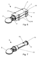
- FIG. 1 to 9 show a preferred embodiment and parts of the preferred embodiment of a Hochlastzuginate 1 for a vehicle trailer, wherein a coupling element 2 having straight shaft 3 is arranged in a bearing housing 4, on the coupling element 2 side facing away from the shaft 3, a securing element 5 of the shaft 3 on the Bearing housing 4 is supported.
- a Hochlastzuginate 1 is a towing eye, so a device for coupling a vehicle trailer to a towing vehicle, which is designed for receiving high tensile loads and supporting loads, such as those occurring in agriculture, for example.
- the Hochlastzuginate 1 has a coupling element 2, which is provided for coupling with a counter-coupling element, wherein the counter-coupling element may be attached in particular to a towing vehicle.
- the coupling element 2 is formed as a ball socket.
- the coupling element can also have other shapes and be designed, for example, as a ring eyelet.
- the shaft 3 may be particularly preferably formed as a forged part.
- the shaft 3 is arranged partly in the bearing housing 4, wherein the bearing housing 4 is preferably designed such that the bearing housing 4 can be fastened to a drawbar of a vehicle trailer.
- the bearing housing 4 may have a particular planar mounting surface 11, which contacts a drawbar of the vehicle trailer in a fixed state of Hochlastzuginate 1.
- the bearing housing 4 may be particularly preferably formed as a forged part.
- the shank 3 has on a side facing away from the coupling element 2 a securing element 5, which securing element 5 is supported on the bearing housing 4 and thus holds the shaft 3 in the bearing housing.
- the bearing housing 4 is formed divided. In this case, in particular, the bearing housing 4 of two or more bearing housing parts 8.9 exist, in an assembled state of the bearing housing 4, the shaft 3 is held in the bearing housing 4 by a positive connection, and in a disassembled state of the bearing housing 4 of the shaft 3 from the bearing housing 4 can be removed. It can be achieved that for removal or insertion of the shaft 3 in or out of the bearing housing 4, the bearing housing 4 can be opened, and the shaft 3 need not be pushed parallel to its longitudinal axis in the bearing housing 4.
- a vehicle trailer comprising a Hochlastzuginate 1 may be provided, wherein the Hochlastzuginate 1 is formed as described above.
- the vehicle trailer may in particular be an agricultural vehicle trailer.
- the vehicle trailer has a drawbar - that the bearing housing 4 attached to the drawbar, in particular welded or screwed, and that the mounting surface 11 of the bearing housing 4 contacts the drawbar.
- the securing element 5 is supported on an outer side of the bearing housing 4.
- the shaft 3 can reach through the entire bearing housing 4.
- a conventional shaft can be inserted into the bearing housing in an advantageous manner.
- a recess 12 is formed on the outer side of the bearing housing 4, and that the securing element 5 is arranged in the recess 12.
- the bearing housing 4 is closed on the outside of the coupling element 2 outside, and that the securing element 5 is surrounded by the bearing housing 4.
- the shaft 3 is formed in one piece.
- the securing element 5 is formed on the shaft 3.
- a particularly advantageous voltage curve in the shaft 3 can be achieved, since the securing element 5, which receives substantially all the tensile forces, is formed directly on the shaft 3 and the forces can pass well.
- the Hochlastzuginate 1 platzsparent be formed because no space for a fuse element 5 with the remaining shaft 4 connecting screw needs to be present.
- a first part 6 of the shaft 3 is arranged in a receptacle 7 of the bearing housing 4.
- the coupling element 2 may in particular be integrally formed on the first part 6 of the shaft 3, wherein the first part 6 may be formed in particular rotationally symmetrical about a longitudinal axis of the first part 6.
- the longitudinal axis of the shaft 3 may be the longitudinal axis of the first part 6.
- the shaft 3 according to the preferred embodiment of the coupling element 2, the first part 6 and the securing element 5 consist, which together form the one-piece shaft 3.
- the first part 6 of the shaft 3 may have at least one contact surface 13, which is in contact with at least one opposite counter-contact surface 14 of the receptacle 7.
- the at least one contact surface 13 and the at least one mating contact surface 14 may be formed annularly about the longitudinal axis of the shaft 3. According to the preferred embodiment, in each case two contact surface 13 and mating contact surface 14 may be provided.
- the receptacle 7 has a lubricating device, for example comprising a graphite body.
- the lubricating device can be arranged in particular in the region of the at least one contact surface 13 and lubricate the contact surface 13.
- the bearing housing 4 has a first bearing housing part 8 and a second bearing housing part 9.
- the first bearing housing part 8 and the second bearing housing part 9 can be substantially the same size.
- the bearing housing 4 may be particularly simple and robust. In a vehicle trailer here, the first bearing housing part 8 or the second bearing housing part 9 may be attached to the drawbar.
- the bearing housing 4 is divided substantially along a first plane, and that a longitudinal axis of the shaft 3 in the first level is arranged.
- the bearing housing parts 8, 9 can essentially each have a semicylindrical receptacle 7.
- the two bearing housing parts 8, 9 can be designed as essentially two semicylindrical shells which hold the shaft 3.
- a particularly good handling and a stable construction can be achieved.
- the two bearing housing parts 8,9 can be particularly easily formed as forgings.
- first bearing housing part 8 and the second bearing housing part 9 are connected to each other in a non-destructive detachable manner.
- first bearing housing part 8 and the second bearing housing part 9 can be screwed together. Thereby, a simple and repeatable opening of the bearing housing 4 can be achieved.
- first bearing housing part 8 and the second bearing housing part 9 have aligned connecting means receptacles 17, which connecting means receptacles 17 may be provided in particular for receiving screws.
- a central axis of the connecting means receptacles 17 may be in particular normal to the longitudinal axis of the shaft 3.
- the connecting means receptacles 17 of the bearing housing part 8, 9 which can be fastened to the vehicle trailer can have a thread into which the screw 18 engages.
- connection means receptacles 17 are formed thread-free.
- the screws 18 can pass through the two bearing housing parts 8,9 and engage in a trained in the drawbar thread, the screws 18, the bearing housing parts 8.9 fastened together and to the drawbar. As a result, the number of required connection means can be kept low.
- first bearing housing part 8 and the second bearing housing part 9 have at least one latching extension 15 and at least one opposite latching projection receptacle 16. In this case, a lateral displacement of the two bearing housing parts 8,9 to each other can be prevented. According to the preferred embodiment, four pairs of latching extensions 15 and latching projection receptacles 16 are provided.
- the at least one mating contact surface 14 is arranged in a region between two connecting means receptacles 17.
- forces acting on the shaft 3 can be forwarded to the bearing housing 4 at particularly well fastened areas of the bearing housing 4.
- connecting means receptacles 17 are provided, which are each formed in half in the first bearing housing part 8 and the second bearing housing part 9.
- the four connecting means receptacles 17 are divided into two pairs, each pair having two connecting means receptacles 17, which lead on both sides of the shaft 3 over.
- a mating contact surface 14 may be formed in the pairing of the connecting means receptacles 17, a mating contact surface 14 may be formed.
- the shaft 3 has an anti-rotation extension 10.
- the anti-rotation extension 10 prevents rotation of the shaft 4 about the longitudinal axis.
- the anti-rotation extension 10 may be formed in particular in the first part 6, wherein in the receptacle 7, as in Fig. 4 represented, a Drehêtsnut 19 is formed, in which the anti-rotation extension 10 can engage. Due to the split design of the bearing housing 4 in this case the rotation lock can be designed to be particularly simple and reliable.
- the anti-rotation groove 19 may be formed in particular in both bearing housing parts 8.
- the shaft 4 can be installed rotated if necessary by 180 °.
- a cable channel is formed in the receptacle 7.
- the cable duct can be provided for the passage of electrical cables, it being particularly advantageous here if a cable connection between towing vehicle and vehicle trailer takes place immediately adjacent to the coupling element 2. Due to the split design of the bearing housing 4, the cable channel be particularly easily formed milled into the receptacle.
- sensors may be mounted on the shaft 4, for example on the coupling element 2 or on the first part 6 of the shaft 3.
- These sensors may, for example, comprise strain gauges which measure the tensile and / or bending loads, thereby exceeding the designed load or an impending material failure can be reliably detected.
- the supply of the cables for the sensors can be done in particular via the cable channel.
Landscapes
- Engineering & Computer Science (AREA)
- Transportation (AREA)
- Mechanical Engineering (AREA)
- Mounting Of Bearings Or Others (AREA)
- Rolling Contact Bearings (AREA)
- Motor Power Transmission Devices (AREA)
Abstract
Description
- Die Erfindung betrifft eine Hochlastzugöse gemäß dem Oberbegriff des Patentanspruches 1.
- Hochlastzugösen sind Zugösen, welche zum Ziehen von schweren Anhängern, beispielsweise im Bereich der Landwirtschaft, verwendet werden. Hierbei sind Hochlastzugösen bekannt, welche ein an dem Anhänger befestigbares Lagergehäuse aufweisen, wobei ein ein Kupplungselement aufweisender Schaft in das Lagergehäuse eingesteckt ist und an einer dem Kupplungselement gegenüberliegenden Seite mit einem verschraubten Sicherungselement gesichert ist. Durch diese Bauweise kann der Schaft ausgetauscht werden. Der Schaft ist üblicherweise rotationssymmetrisch um die Mittelachse, wobei ein Durchmesser des Schaftes mit zunehmender Entfernung vom Kupplungselement abnimmt, damit der Schaft in das Lagergehäuse gesteckt werden kann.
- Nachteilig daran ist, dass bei der Gestaltung des Schaftes darauf Rücksicht genommen werden muss, dass dieser in das Lagergehäuse einsteckbar ist. Weiters muss die Schraube, welche das Sicherungselement befestigt, im Betrieb große Zugbelastungen aufnehmen und dementsprechend dimensioniert sein und mit einem entsprechenden Drehmoment befestigt sein, wodurch das Austauschen des Schaftes erschwert ist.
- Aufgabe der Erfindung ist es daher eine Hochlastzugöse der eingangs genannten Art anzugeben, mit welcher die genannten Nachteile vermieden werden können, und welche in der Form besser auf die ausgelegte Belastung angepasst sein kann.
- Erfindungsgemäß wird dies durch die Merkmale des Patentanspruches 1 erreicht.
- Dadurch ergibt sich der Vorteil, dass durch das geteilte Lagergehäuse die Form des Schaftes frei gewählt und auf die ausgelegte Belastung und den besonderen Erfordernissen besser abgestimmt sein kann. Beispielsweise kann der Durchmesser des Schaftes an jener Stelle am größten sein, an welcher die höchsten Biegemomente auftreten. Dadurch kann die Hochlastzugöse leichter und Materialsparender ausgebildet sein, wobei ein optimaler Verlauf der Spannungsverläufe bei der ausgelegten Belastung erreicht werden kann. Weiters kann der Wechsel des Schaftes erleichtert werden, da ein Öffnen des Lagergehäuses leichter möglich ist als das Abnehmen des Sicherungselementes. Bei dem Einbau oder Ausbau des Schaftes ist es weiters von Vorteil, dass dieser seitlich eingelegt werden kann und nicht frontal eingeschoben werden braucht, da dadurch ein geringerer Platzbedarf notwendig ist.
- Die Unteransprüche betreffen weitere vorteilhafte Ausgestaltungen der Erfindung.
- Ausdrücklich wird hiermit auf den Wortlaut der Patentansprüche Bezug genommen, wodurch die Ansprüche an dieser Stelle durch Bezugnahme in die Beschreibung eingefügt sind und als wörtlich wiedergegeben gelten.
- Die Erfindung wird unter Bezugnahme auf die beigeschlossenen Zeichnungen, in welchen lediglich eine bevorzugte Ausführungsform beispielhaft dargestellt ist, näher beschrieben. Dabei zeigt:
-
Fig. 1 zeigt eine bevorzugte Ausführungsform einer Hochlastzugöse als Explosionsdarstellung; -
Fig. 2 zeigt ein Lagergehäuse der bevorzugten Ausführungsform einer Hochlastzugöse in Seitenansicht; -
Fig. 3 zeigt das Lagergehäuse der bevorzugten Ausführungsform in Vorderansicht; -
Fig. 4 zeigt den Schnitt entlang der Linie A-A inFig. 2 ; -
Fig. 5 zeigt das Lagergehäuse der bevorzugten Ausführungsform in Draufsicht; -
Fig. 6 bevorzugte Ausführungsform einer Hochlastzugöse in einer axonometrischen Darstellung; -
Fig. 7 zeigt einen Schaft der bevorzugten Ausführungsform einer Hochlastzugöse in einer axonometrischen Darstellung; -
Fig. 8 zeigt das Lagergehäuse der bevorzugten Ausführungsform in einer axonometrischen Darstellung; und -
Fig. 9 zeigt das Lagergehäuse der bevorzugten Ausführungsform als Explosionsdarstellung; - Die
Fig. 1 bis 9 zeigen eine bevorzugte Ausführungsform und Teile der bevorzugten Ausführungsform einer Hochlastzugöse 1 für einen Fahrzeuganhänger, wobei ein ein Kuppelelement 2 aufweisender gerader Schaft 3 in einem Lagergehäuse 4 angeordnet ist, auf der dem Kuppelelement 2 abgewandten Seite des Schaftes 3 ein Sicherungselement 5 des Schaftes 3 an dem Lagergehäuse 4 abgestützt ist. Eine Hochlastzugöse 1 ist eine Zugöse, also eine Vorrichtung zum Kuppeln eines Fahrzeuganhängers an ein Zugfahrzeug, welche für die Aufnahme hoher Zuglasten und Stützlasten, wie diese beispielsweise in der Landwirtschaft auftreten, ausgebildet ist. - Hierbei weist die Hochlastzugöse 1 ein Kuppelelement 2 auf, welches zum Kuppeln mit einem Gegenkupplungselement vorgesehen ist, wobei das Gegenkupplungselement insbesondere an einem Zugfahrzeug befestigt sein kann.
- Wie in
Fig. 1 ,6 und 7 dargestellt kann bei der bevorzugten Ausführungsform insbesondere vorgesehen sein, dass das Kuppelelement 2 als Kugelpfanne ausgebildet ist. Dass Kupplungselement kann aber auch andere Formen aufweisen und beispielsweise als Ringöse ausgebildet sein. - Der Schaft 3 kann besonders bevorzugt als Schmiedeteil ausgebildet sein.
- Der Schaft 3 ist zum Teil in dem Lagergehäuse 4 angeordnet, wobei das Lagergehäuse 4 vorzugsweise derart ausgebildet ist, dass das Lagergehäuse 4 an eine Deichsel eines Fahrzeuganhängers befestigbar ist. Hierbei kann das Lagergehäuse 4 eine insbesondere ebene Befestigungsfläche 11 aufweisen, welche in einem befestigten Zustand der Hochlastzugöse 1 eine Deichsel des Fahrzeuganhängers kontaktiert.
- Das Lagergehäuse 4 kann besonders bevorzugt als Schmiedeteil ausgebildet sein.
- Der Schaft 3 weist an einer dem Kuppelelement 2 abgewandten Seite ein Sicherungselement 5 auf, welches Sicherungselement 5 an dem Lagergehäuse 4 abgestützt ist und derart den Schaft 3 in dem Lagergehäuse hält.
- Vorgesehen ist, dass das Lagergehäuse 4 geteilt ausgebildet ist. Hierbei kann insbesondere das Lagergehäuse 4 aus zwei oder mehr Lagergehäuseteile 8,9 bestehen, wobei in einem zusammengesetzten Zustand des Lagergehäuses 4 der Schaft 3 im Lagergehäuse 4 durch einen Formschluss gehalten ist, und in einem auseinandergenommenen Zustand des Lagergehäuses 4 der Schaft 3 aus dem Lagergehäuse 4 entnehmbar ist. Dabei kann erreicht werden, dass zur Entnahme oder Einbringung des Schaftes 3 in oder aus dem Lagergehäuse 4 das Lagergehäuse 4 geöffnet werden kann, und der Schaft 3 nicht parallel zu seiner Längsachse in das Lagergehäuse 4 geschoben werden braucht.
- Weiters kann ein Fahrzeuganhänger umfassend eine Hochlastzugöse 1 vorgesehen sein, wobei die Hochlastzugöse 1 wie vorstehend beschrieben ausgebildet ist. Der Fahrzeuganhänger kann insbesondere ein landwirtschaftlicher Fahrzeuganhänger sein. Weiters kann vorgesehen sein, dass der Fahrzeuganhänger eine Deichsel - aufweist, dass das Lagergehäuse 4 an der Deichsel befestigt, insbesondere verschweißt oder verschraubt, ist, und dass die Befestigungsfläche 11 des Lagergehäuses 4 die Deichsel kontaktiert.
- Vorzugsweise kann vorgesehen sein, das Sicherungselement 5 an einer Außenseite des Lagergehäuses 4 abgestützt ist. Hierbei kann der Schaft 3 durch das gesamte Lagergehäuse 4 reichen. Dabei kann in vorteilhafter Weise auch ein herkömmlicher Schaft in das Lagergehäuse eingelegt werden.
- Insbesondere kann hierbei vorgesehen sein, dass eine Vertiefung 12 an der Außenseite des Lagergehäuses 4 ausgebildet ist, und dass das Sicherungselement 5 in der Vertiefung 12 angeordnet ist.
- Alternativ kann vorgesehen sein, dass das Lagergehäuse 4 an der dem Kuppelelement 2 gegenüberliegenden Außenseite geschlossen ist, und dass das Sicherungselement 5 von dem Lagergehäuse 4 umgeben ist.
- Besonders bevorzugt kann vorgesehen sein, dass der Schaft 3 einstückig ausgebildet ist. Insbesondere kann vorgesehen sein, dass das Sicherungselement 5 am Schaft 3 angeformt ist. Dabei kann ein besonders vorteilhafter Spannungsverlauf im Schaft 3 erreicht werden, da das Sicherungselement 5, welches im Wesentlichen alle Zugkräfte aufnimmt, direkt am Schaft 3 angeformt ist und die Kräfte gut weiterleiten kann. Weiters kann dadurch die Hochlastzugöse 1 platzsparrender ausgebildet sein, weil kein Platz für eine das Sicherungselement 5 mit dem restlichen Schaft 4 verbindende Schraube vorhanden sein braucht.
- Besonders bevorzugt kann vorgesehen sein, dass ein erster Teil 6 des Schaftes 3 in einer Aufnahme 7 des Lagergehäuses 4 angeordnet ist. Das Kuppelelement 2 kann insbesondere an dem ersten Teil 6 des Schaftes 3 angeformt sein, wobei der erste Teil 6 insbesondere rotationssymmetrisch um eine Längsachse des ersten Teils 6 ausgebildet sein kann. Die Längsachse des Schaftes 3 kann hierbei die Längsachse des ersten Teils 6 sein.
- Hierbei kann der Schaft 3 gemäß der bevorzugten Ausführungsform aus dem Kuppelelement 2, dem ersten Teil 6 und dem Sicherungselement 5 bestehen, welche zusammen den einstückigen Schaft 3 ausbilden.
- Vorzugsweise kann der erste Teil 6 des Schaftes 3 wenigstens eine Kontaktfläche 13 aufweisen, welche mit wenigstens einer gegengleichen Gegenkontaktfläche 14 der Aufnahme 7 in Kontakt ist. Hierbei kann die wenigstens eine Kontaktfläche 13 und die wenigstens eine Gegenkontaktfläche 14 ringförmig um die Längsachse des Schaftes 3 ausgebildet sein. Gemäß der bevorzugten Ausführungsform können jeweils zwei Kontaktfläche 13 und Gegenkontaktfläche 14 vorgesehen sein.
- Weiters kann vorgesehen sein, dass die Aufnahme 7 eine Schmiervorrichtung, beispielsweise umfassend einen Grafitkörper, aufweist. Die Schmiervorrichtung kann insbesondere im Bereich der wenigstens einen Kontaktfläche 13 angeordnet sein und die Kontaktfläche 13 schmieren.
- Wie in
Fig. 1 bis Fig. 6 , sowieFig. 8 und Fig. 9 dargestellt kann vorzugsweise vorgesehen sein, dass das Lagergehäuse 4 ein erstes Lagergehäuseteil 8 und ein zweites Lagergehäuseteil 9 aufweist. Besonders bevorzugt kann der erste Lagergehäuseteil 8 und der zweite Lagergehäuseteil 9 im Wesentlichen gleich groß sein. Hierbei kann das Lagergehäuse 4 besonders einfach und robust ausgebildet sein. Bei einem Fahrzeuganhänger kann hierbei der erste Lagergehäuseteil 8 oder der zweite Lagergehäuseteil 9 an der Deichsel befestigt sein. - Vorzugsweise kann vorgesehen sein, dass das Lagergehäuse 4 im Wesentlichen entlang einer ersten Ebene geteilt ist, und dass eine Längsachse des Schaftes 3 in der ersten Ebene angeordnet ist. Herbei können die Lagergehäuseteile 8,9 im Wesentlichen jeweils eine halbzylinderförmige Aufnahme 7 aufweisen. Durch diese Ausführung können die beiden Lagergehäuseteile 8,9 als im Wesentlichen zwei halbzylinderförmige Schalen ausgebildet sein, welche den Schaft 3 halten. Hierbei kann eine besonders gute Handhabung und eine stabile Bauweise erreicht werden. Weiters können die beiden Lagergehäuseteile 8,9 besonders einfach als Schmiedeteile ausgebildet sein.
- Besonders bevorzugt kann vorgesehen sein, dass das erste Lagergehäuseteil 8 und das zweite Lagergehäuseteil 9 zerstörungsfrei lösbar miteinander verbunden sind. Insbesondere können das erste Lagergehäuseteil 8 und das zweite Lagergehäuseteil 9 miteinander verschraubbar sein. Dadurch kann ein einfaches und wiederholbares Öffnen des Lagergehäuses 4 erreicht werden.
- Hierbei kann vorgesehen sein, dass das erste Lagergehäuseteil 8 und der zweite Lagergehäuseteil 9 fluchtende Verbindungsmittelaufnahmen 17 aufweist, welche Verbindungsmittelaufnahmen 17 insbesondere zur Aufnahme von Schrauben vorgesehen sein. Eine Mittelachse der Verbindungsmittelaufnahmen 17 kann insbesondere normal zu der Längsachse des Schaftes 3 sein.
- Gemäß der bevorzugten Ausführungsform können die Verbindungsmittelaufnahmen 17 des an dem Fahrzeuganhänger befestigbaren Lagergehäuseteils 8,9 ein Gewinde aufweisen, in welche die Schraube 18 eingreifen.
- Alternativ kann vorgesehen sein, dass die Verbindungsmittelaufnahmen 17 gewindefrei ausgebildet sind. Hierbei können die Schrauben 18 durch die beiden Lagergehäuseteile 8,9 durchgreifen und in ein in der Deichsel ausgebildetes Gewinde eingreifen, wobei die Schrauben 18 die Lagergehäuseteile 8,9 miteinander und an der Deichsel befestigen. Dadurch kann die Zahl der benötigten Verbindungsmittel gering gehalten werden.
- Weiters kann vorgesehen sein, dass der erste Lagergehäuseteil 8 und der zweite Lagergehäuseteil 9 wenigstens einen Rastfortsatz 15 und wenigstens eine gegengleiche Rastfortsatzaufnahme 16 aufweisen. Hierbei kann ein seitliches Verschieben der beiden Lagergehäuseteile 8,9 zueinander unterbunden werden. Gemäß der bevorzugten Ausführungsform sind vier Paare an Rastfortsätzen 15 und Rastfortsatzaufnahmen 16 vorgesehen.
- Bevorzugt kann weiters vorgesehen sein, dass die wenigstens eine Gegenkontaktfläche 14 in einem Bereich zwischen zwei Verbindungsmittelaufnahmen 17 angeordnet ist. Dadurch können auf den Schaft 3 einwirkende Kräfte an besonders gut befestigten Bereichen des Lagergehäuses 4 an das Lagergehäuse 4 weitergeleitet werden.
- In der bevorzugten Ausführungsform sind vier Verbindungsmittelaufnahmen 17 vorgesehen, welche jeweils zur Hälfte in dem ersten Lagergehäuseteil 8 und dem zweiten Lagergehäuseteil 9 ausgebildet sind. Hierbei sind die vier Verbindungsmittelaufnahmen 17 zu zwei Paaren aufgeteilt, wobei jedes Paar zwei Verbindungsmittelaufnahmen 17 aufweist, welche beidseitig am Schaft 3 vorbei führen. Hierbei kann bei dem Paaren der Verbindungsmittelaufnahmen 17 eine Gegenkontaktfläche 14 ausgebildet sein.
- Bevorzugt kann weiters vorgesehen sein, dass der Schaft 3 einen Drehsicherungsfortsatz 10 aufweist. Der Drehsicherungsfortsatz 10 verhindert eine Verdrehung des Schaftes 4 um die Längsachse. Hierbei kann der Drehsicherungsfortsatz 10 insbesondere im ersten Teil 6 angeformt sein, wobei in der Aufnahme 7, wie in
Fig. 4 dargestellt, eine Drehsicherungsnut 19 ausgebildet ist, in welche der Drehsicherungsfortsatz 10 eingreifen kann. Durch die geteilte Ausbildung des Lagergehäuses 4 kann hierbei die Drehsicherung besonders einfach und zuverlässig ausgebildet sein. - Die Drehsicherungsnut 19 kann insbesondere in beiden Lagergehäuseteile 8 ausgebildet sein. Hierbei kann der Schaft 4 bei Bedarf um 180° verdreht eingebaut werden.
- Weiters kann vorgesehen sein, dass in der Aufnahme 7 ein Kabelkanal ausgebildet ist. Der Kabelkanal kann zur Durchleitung elektrischer Kabel vorgesehen sein, wobei es hierbei besonders vorteilhaft ist, wenn eine Kabelverbindung zwischen Zugfahrzeug und Fahrzeuganhänger unmittelbar benachbart zu dem Kuppelelement 2 erfolgt. Durch die geteilte Ausbildung des Lagergehäuses 4 kann der Kabelkanal besonders leicht in die Aufnahme eingefräst ausgebildet sein.
- Weiters kann vorgesehen sein, dass am Schaft 4 Sensoren angebracht sind, beispielsweise am Kuppelelement 2 oder am ersten Teil 6 des Schaftes 3. Diese Sensoren können beispielsweise Dehnungsmessstreifen umfassen, welche die Zug- und/oder Biegebelastungen messen, wodurch eine Überschreitung der ausgelegten Belastung oder ein sich anbahnendes Materialversagen zuverlässig erkannt werden kann. Die Zuleitung der Kabeln für die Sensoren kann insbesondere über den Kabelkanal erfolgen.
Claims (10)
- Hochlastzugöse (1) für einen Fahrzeuganhänger, wobei ein ein Kuppelelement (2) aufweisender gerader Schaft (3) in einem Lagergehäuse (4) angeordnet ist, auf der dem Kuppelelement (2) abgewandten Seite des Schaftes (3) ein Sicherungselement (5) des Schaftes (3) an dem Lagergehäuse (4) abgestützt ist, dadurch gekennzeichnet, dass das Lagergehäuse (4) geteilt ausgebildet ist.
- Hochlastzugöse (1) nach Anspruch 1, dadurch gekennzeichnet, dass das Sicherungselement (5) an einer Außenseite des Lagergehäuses (4) abgestützt ist.
- Hochlastzugöse (1) nach Anspruch 1 oder 2, dadurch gekennzeichnet, dass der Schaft (3) einstückig ausgebildet ist.
- Hochlastzugöse (1) nach einem der Ansprüche 1 bis 3, dadurch gekennzeichnet, dass ein erster Teil (6) des Schaftes (3) in einer Aufnahme (7) des Lagergehäuses (4) angeordnet ist.
- Hochlastzugöse (1) nach einem der Ansprüche 1 bis 4, dadurch gekennzeichnet, dass das Lagergehäuse (4) ein erstes Lagergehäuseteil (8) und ein zweites Lagergehäuseteil (9) aufweist.
- Hochlastzugöse (1) nach Anspruch 5, dadurch gekennzeichnet, dass das erste Lagergehäuseteil (8) und das zweite Lagergehäuseteil (9) zerstörungsfrei lösbar miteinander verbunden sind.
- Hochlastzugöse (1) nach einem der Ansprüche 1 bis 6, dadurch gekennzeichnet, dass das Lagergehäuse (4) im Wesentlichen entlang einer ersten Ebene geteilt ist, und dass eine Längsachse des Schaftes (3) in der ersten Ebene angeordnet ist.
- Hochlastzugöse (1) nach einem der Ansprüche 1 bis 7, dadurch gekennzeichnet, dass der Schaft (3) einen Drehsicherungsfortsatz (10) aufweist.
- Hochlastzugöse (1) nach einem der Ansprüche 4 bis 8, dadurch gekennzeichnet, dass in der Aufnahme (7) ein Kabelkanal ausgebildet ist.
- Fahrzeuganhänger umfassend eine Hochlastzugöse (1) nach einem der Ansprüche 1 bis 9.
Applications Claiming Priority (1)
| Application Number | Priority Date | Filing Date | Title |
|---|---|---|---|
| ATA495/2013A AT514455B1 (de) | 2013-06-19 | 2013-06-19 | Hochlastzugöse |
Publications (2)
| Publication Number | Publication Date |
|---|---|
| EP2815899A1 true EP2815899A1 (de) | 2014-12-24 |
| EP2815899B1 EP2815899B1 (de) | 2018-09-19 |
Family
ID=50877225
Family Applications (1)
| Application Number | Title | Priority Date | Filing Date |
|---|---|---|---|
| EP14450027.9A Active EP2815899B1 (de) | 2013-06-19 | 2014-05-22 | Hochlastzugöse |
Country Status (2)
| Country | Link |
|---|---|
| EP (1) | EP2815899B1 (de) |
| AT (1) | AT514455B1 (de) |
Families Citing this family (2)
| Publication number | Priority date | Publication date | Assignee | Title |
|---|---|---|---|---|
| DE102017121356A1 (de) * | 2017-09-14 | 2019-03-14 | ACPS Automotive GmbH | Anhängekupplung |
| DE102017121369A1 (de) * | 2017-09-14 | 2019-03-14 | ACPS Automotive GmbH | Anhängekupplung |
Citations (4)
| Publication number | Priority date | Publication date | Assignee | Title |
|---|---|---|---|---|
| DE1865806U (de) * | 1962-09-15 | 1963-01-17 | Jellinghaus & Co | Geteilte zugoese. |
| US3169783A (en) * | 1962-07-30 | 1965-02-16 | Western Unit Corp | Drawbar hitch assembly |
| DE10153032A1 (de) * | 2001-10-26 | 2002-07-18 | Audi Ag | Abschleppvorrichtung für ein Kraftfahrzeug |
| EP2080644A1 (de) * | 2008-01-18 | 2009-07-22 | Redrock Engineering limited | Schwenkanhängerkupplung |
-
2013
- 2013-06-19 AT ATA495/2013A patent/AT514455B1/de not_active IP Right Cessation
-
2014
- 2014-05-22 EP EP14450027.9A patent/EP2815899B1/de active Active
Patent Citations (4)
| Publication number | Priority date | Publication date | Assignee | Title |
|---|---|---|---|---|
| US3169783A (en) * | 1962-07-30 | 1965-02-16 | Western Unit Corp | Drawbar hitch assembly |
| DE1865806U (de) * | 1962-09-15 | 1963-01-17 | Jellinghaus & Co | Geteilte zugoese. |
| DE10153032A1 (de) * | 2001-10-26 | 2002-07-18 | Audi Ag | Abschleppvorrichtung für ein Kraftfahrzeug |
| EP2080644A1 (de) * | 2008-01-18 | 2009-07-22 | Redrock Engineering limited | Schwenkanhängerkupplung |
Also Published As
| Publication number | Publication date |
|---|---|
| AT514455A1 (de) | 2015-01-15 |
| EP2815899B1 (de) | 2018-09-19 |
| AT514455B1 (de) | 2015-03-15 |
Similar Documents
| Publication | Publication Date | Title |
|---|---|---|
| EP3050167B1 (de) | Elektrische anschlussklemme | |
| DE102015015202B4 (de) | Steckverbinder und Stecksystem | |
| DE102012008483A1 (de) | Federkontakte | |
| DE102012101813B3 (de) | Steckverbinder | |
| DE202008005394U1 (de) | Hochstromleiterplattensteckverbinder | |
| DE102015210336A1 (de) | Halteblock und modularer Steckereinsatz | |
| DE102010017361A1 (de) | Anbausteckverbinder | |
| DE69917983T2 (de) | Kontaktstift | |
| EP3358682B1 (de) | Elektrischer steckverbinder und elektrisches stecksystem | |
| EP0949711A2 (de) | Kabelsteckverbinder | |
| EP2815899B1 (de) | Hochlastzugöse | |
| DE202010010418U1 (de) | Rundsteckverbinder | |
| DE2239476A1 (de) | Elektrischer verbinder und verfahren zur herstellung einer verbindung | |
| DE202023002957U1 (de) | Hochstromsteckverbindersystem mit einstellbarer Trennkraft | |
| DE102017222809B4 (de) | Elektrischer Steckverbinder und Steckverbindung | |
| DE102020120306A1 (de) | Rundsteckverbinder mit Schirmanbindung | |
| EP2940803B1 (de) | Verbinder für elektrische Energiekabel | |
| DE102013105602A1 (de) | Anschlusselement für Steckverbinder | |
| EP3123566B1 (de) | Kontaktbuchse für eine steckdose oder kupplung | |
| DE202013001891U1 (de) | Steckverbinder | |
| DE202017107625U1 (de) | Elektrischer Steckverbinder | |
| DE102014006201A1 (de) | Kabelschuh, insbesondere für ein Kraftfahrzeug | |
| WO2019001644A1 (de) | Zwitterartiges kontaktelement | |
| EP3439118B1 (de) | Schraubsystem, schraubverbinder und verfahren zur herstellung eines schraubverbinders | |
| AT16923U1 (de) | Einbausteckverbinder |
Legal Events
| Date | Code | Title | Description |
|---|---|---|---|
| PUAI | Public reference made under article 153(3) epc to a published international application that has entered the european phase |
Free format text: ORIGINAL CODE: 0009012 |
|
| 17P | Request for examination filed |
Effective date: 20140522 |
|
| AK | Designated contracting states |
Kind code of ref document: A1 Designated state(s): AL AT BE BG CH CY CZ DE DK EE ES FI FR GB GR HR HU IE IS IT LI LT LU LV MC MK MT NL NO PL PT RO RS SE SI SK SM TR |
|
| AX | Request for extension of the european patent |
Extension state: BA ME |
|
| R17P | Request for examination filed (corrected) |
Effective date: 20150624 |
|
| RAX | Requested extension states of the european patent have changed |
Extension state: BA Payment date: 20150624 Extension state: ME Payment date: 20150624 |
|
| RBV | Designated contracting states (corrected) |
Designated state(s): AL AT BE BG CH CY CZ DE DK EE ES FI FR GB GR HR HU IE IS IT LI LT LU LV MC MK MT NL NO PL PT RO RS SE SI SK SM TR |
|
| GRAP | Despatch of communication of intention to grant a patent |
Free format text: ORIGINAL CODE: EPIDOSNIGR1 |
|
| STAA | Information on the status of an ep patent application or granted ep patent |
Free format text: STATUS: GRANT OF PATENT IS INTENDED |
|
| INTG | Intention to grant announced |
Effective date: 20180508 |
|
| GRAS | Grant fee paid |
Free format text: ORIGINAL CODE: EPIDOSNIGR3 |
|
| GRAA | (expected) grant |
Free format text: ORIGINAL CODE: 0009210 |
|
| STAA | Information on the status of an ep patent application or granted ep patent |
Free format text: STATUS: THE PATENT HAS BEEN GRANTED |
|
| AK | Designated contracting states |
Kind code of ref document: B1 Designated state(s): AL AT BE BG CH CY CZ DE DK EE ES FI FR GB GR HR HU IE IS IT LI LT LU LV MC MK MT NL NO PL PT RO RS SE SI SK SM TR |
|
| AX | Request for extension of the european patent |
Extension state: BA ME |
|
| REG | Reference to a national code |
Ref country code: GB Ref legal event code: FG4D Free format text: NOT ENGLISH |
|
| REG | Reference to a national code |
Ref country code: CH Ref legal event code: EP |
|
| REG | Reference to a national code |
Ref country code: AT Ref legal event code: REF Ref document number: 1042828 Country of ref document: AT Kind code of ref document: T Effective date: 20181015 |
|
| REG | Reference to a national code |
Ref country code: IE Ref legal event code: FG4D Free format text: LANGUAGE OF EP DOCUMENT: GERMAN |
|
| REG | Reference to a national code |
Ref country code: DE Ref legal event code: R096 Ref document number: 502014009513 Country of ref document: DE |
|
| REG | Reference to a national code |
Ref country code: NL Ref legal event code: FP |
|
| PG25 | Lapsed in a contracting state [announced via postgrant information from national office to epo] |
Ref country code: GR Free format text: LAPSE BECAUSE OF FAILURE TO SUBMIT A TRANSLATION OF THE DESCRIPTION OR TO PAY THE FEE WITHIN THE PRESCRIBED TIME-LIMIT Effective date: 20181220 Ref country code: FI Free format text: LAPSE BECAUSE OF FAILURE TO SUBMIT A TRANSLATION OF THE DESCRIPTION OR TO PAY THE FEE WITHIN THE PRESCRIBED TIME-LIMIT Effective date: 20180919 Ref country code: LT Free format text: LAPSE BECAUSE OF FAILURE TO SUBMIT A TRANSLATION OF THE DESCRIPTION OR TO PAY THE FEE WITHIN THE PRESCRIBED TIME-LIMIT Effective date: 20180919 Ref country code: BG Free format text: LAPSE BECAUSE OF FAILURE TO SUBMIT A TRANSLATION OF THE DESCRIPTION OR TO PAY THE FEE WITHIN THE PRESCRIBED TIME-LIMIT Effective date: 20181219 Ref country code: SE Free format text: LAPSE BECAUSE OF FAILURE TO SUBMIT A TRANSLATION OF THE DESCRIPTION OR TO PAY THE FEE WITHIN THE PRESCRIBED TIME-LIMIT Effective date: 20180919 Ref country code: NO Free format text: LAPSE BECAUSE OF FAILURE TO SUBMIT A TRANSLATION OF THE DESCRIPTION OR TO PAY THE FEE WITHIN THE PRESCRIBED TIME-LIMIT Effective date: 20181219 Ref country code: RS Free format text: LAPSE BECAUSE OF FAILURE TO SUBMIT A TRANSLATION OF THE DESCRIPTION OR TO PAY THE FEE WITHIN THE PRESCRIBED TIME-LIMIT Effective date: 20180919 |
|
| REG | Reference to a national code |
Ref country code: LT Ref legal event code: MG4D |
|
| PG25 | Lapsed in a contracting state [announced via postgrant information from national office to epo] |
Ref country code: HR Free format text: LAPSE BECAUSE OF FAILURE TO SUBMIT A TRANSLATION OF THE DESCRIPTION OR TO PAY THE FEE WITHIN THE PRESCRIBED TIME-LIMIT Effective date: 20180919 Ref country code: LV Free format text: LAPSE BECAUSE OF FAILURE TO SUBMIT A TRANSLATION OF THE DESCRIPTION OR TO PAY THE FEE WITHIN THE PRESCRIBED TIME-LIMIT Effective date: 20180919 Ref country code: AL Free format text: LAPSE BECAUSE OF FAILURE TO SUBMIT A TRANSLATION OF THE DESCRIPTION OR TO PAY THE FEE WITHIN THE PRESCRIBED TIME-LIMIT Effective date: 20180919 |
|
| PG25 | Lapsed in a contracting state [announced via postgrant information from national office to epo] |
Ref country code: CZ Free format text: LAPSE BECAUSE OF FAILURE TO SUBMIT A TRANSLATION OF THE DESCRIPTION OR TO PAY THE FEE WITHIN THE PRESCRIBED TIME-LIMIT Effective date: 20180919 Ref country code: RO Free format text: LAPSE BECAUSE OF FAILURE TO SUBMIT A TRANSLATION OF THE DESCRIPTION OR TO PAY THE FEE WITHIN THE PRESCRIBED TIME-LIMIT Effective date: 20180919 Ref country code: IT Free format text: LAPSE BECAUSE OF FAILURE TO SUBMIT A TRANSLATION OF THE DESCRIPTION OR TO PAY THE FEE WITHIN THE PRESCRIBED TIME-LIMIT Effective date: 20180919 Ref country code: EE Free format text: LAPSE BECAUSE OF FAILURE TO SUBMIT A TRANSLATION OF THE DESCRIPTION OR TO PAY THE FEE WITHIN THE PRESCRIBED TIME-LIMIT Effective date: 20180919 Ref country code: IS Free format text: LAPSE BECAUSE OF FAILURE TO SUBMIT A TRANSLATION OF THE DESCRIPTION OR TO PAY THE FEE WITHIN THE PRESCRIBED TIME-LIMIT Effective date: 20190119 Ref country code: ES Free format text: LAPSE BECAUSE OF FAILURE TO SUBMIT A TRANSLATION OF THE DESCRIPTION OR TO PAY THE FEE WITHIN THE PRESCRIBED TIME-LIMIT Effective date: 20180919 Ref country code: PL Free format text: LAPSE BECAUSE OF FAILURE TO SUBMIT A TRANSLATION OF THE DESCRIPTION OR TO PAY THE FEE WITHIN THE PRESCRIBED TIME-LIMIT Effective date: 20180919 |
|
| PG25 | Lapsed in a contracting state [announced via postgrant information from national office to epo] |
Ref country code: PT Free format text: LAPSE BECAUSE OF FAILURE TO SUBMIT A TRANSLATION OF THE DESCRIPTION OR TO PAY THE FEE WITHIN THE PRESCRIBED TIME-LIMIT Effective date: 20190119 Ref country code: SK Free format text: LAPSE BECAUSE OF FAILURE TO SUBMIT A TRANSLATION OF THE DESCRIPTION OR TO PAY THE FEE WITHIN THE PRESCRIBED TIME-LIMIT Effective date: 20180919 Ref country code: SM Free format text: LAPSE BECAUSE OF FAILURE TO SUBMIT A TRANSLATION OF THE DESCRIPTION OR TO PAY THE FEE WITHIN THE PRESCRIBED TIME-LIMIT Effective date: 20180919 |
|
| REG | Reference to a national code |
Ref country code: DE Ref legal event code: R097 Ref document number: 502014009513 Country of ref document: DE |
|
| PLBE | No opposition filed within time limit |
Free format text: ORIGINAL CODE: 0009261 |
|
| STAA | Information on the status of an ep patent application or granted ep patent |
Free format text: STATUS: NO OPPOSITION FILED WITHIN TIME LIMIT |
|
| PG25 | Lapsed in a contracting state [announced via postgrant information from national office to epo] |
Ref country code: DK Free format text: LAPSE BECAUSE OF FAILURE TO SUBMIT A TRANSLATION OF THE DESCRIPTION OR TO PAY THE FEE WITHIN THE PRESCRIBED TIME-LIMIT Effective date: 20180919 |
|
| 26N | No opposition filed |
Effective date: 20190620 |
|
| PG25 | Lapsed in a contracting state [announced via postgrant information from national office to epo] |
Ref country code: SI Free format text: LAPSE BECAUSE OF FAILURE TO SUBMIT A TRANSLATION OF THE DESCRIPTION OR TO PAY THE FEE WITHIN THE PRESCRIBED TIME-LIMIT Effective date: 20180919 |
|
| REG | Reference to a national code |
Ref country code: CH Ref legal event code: PL |
|
| REG | Reference to a national code |
Ref country code: NL Ref legal event code: MM Effective date: 20190601 |
|
| GBPC | Gb: european patent ceased through non-payment of renewal fee |
Effective date: 20190522 |
|
| PG25 | Lapsed in a contracting state [announced via postgrant information from national office to epo] |
Ref country code: CH Free format text: LAPSE BECAUSE OF NON-PAYMENT OF DUE FEES Effective date: 20190531 Ref country code: LI Free format text: LAPSE BECAUSE OF NON-PAYMENT OF DUE FEES Effective date: 20190531 Ref country code: MC Free format text: LAPSE BECAUSE OF FAILURE TO SUBMIT A TRANSLATION OF THE DESCRIPTION OR TO PAY THE FEE WITHIN THE PRESCRIBED TIME-LIMIT Effective date: 20180919 |
|
| REG | Reference to a national code |
Ref country code: BE Ref legal event code: MM Effective date: 20190531 |
|
| PG25 | Lapsed in a contracting state [announced via postgrant information from national office to epo] |
Ref country code: LU Free format text: LAPSE BECAUSE OF NON-PAYMENT OF DUE FEES Effective date: 20190522 |
|
| PG25 | Lapsed in a contracting state [announced via postgrant information from national office to epo] |
Ref country code: TR Free format text: LAPSE BECAUSE OF FAILURE TO SUBMIT A TRANSLATION OF THE DESCRIPTION OR TO PAY THE FEE WITHIN THE PRESCRIBED TIME-LIMIT Effective date: 20180919 |
|
| PG25 | Lapsed in a contracting state [announced via postgrant information from national office to epo] |
Ref country code: GB Free format text: LAPSE BECAUSE OF NON-PAYMENT OF DUE FEES Effective date: 20190522 Ref country code: NL Free format text: LAPSE BECAUSE OF NON-PAYMENT OF DUE FEES Effective date: 20190601 Ref country code: IE Free format text: LAPSE BECAUSE OF NON-PAYMENT OF DUE FEES Effective date: 20190522 |
|
| PG25 | Lapsed in a contracting state [announced via postgrant information from national office to epo] |
Ref country code: BE Free format text: LAPSE BECAUSE OF NON-PAYMENT OF DUE FEES Effective date: 20190531 |
|
| PG25 | Lapsed in a contracting state [announced via postgrant information from national office to epo] |
Ref country code: FR Free format text: LAPSE BECAUSE OF NON-PAYMENT OF DUE FEES Effective date: 20190531 |
|
| PGFP | Annual fee paid to national office [announced via postgrant information from national office to epo] |
Ref country code: DE Payment date: 20200525 Year of fee payment: 7 |
|
| REG | Reference to a national code |
Ref country code: AT Ref legal event code: MM01 Ref document number: 1042828 Country of ref document: AT Kind code of ref document: T Effective date: 20190522 |
|
| PG25 | Lapsed in a contracting state [announced via postgrant information from national office to epo] |
Ref country code: AT Free format text: LAPSE BECAUSE OF NON-PAYMENT OF DUE FEES Effective date: 20190522 |
|
| PG25 | Lapsed in a contracting state [announced via postgrant information from national office to epo] |
Ref country code: CY Free format text: LAPSE BECAUSE OF FAILURE TO SUBMIT A TRANSLATION OF THE DESCRIPTION OR TO PAY THE FEE WITHIN THE PRESCRIBED TIME-LIMIT Effective date: 20180919 |
|
| PG25 | Lapsed in a contracting state [announced via postgrant information from national office to epo] |
Ref country code: MT Free format text: LAPSE BECAUSE OF FAILURE TO SUBMIT A TRANSLATION OF THE DESCRIPTION OR TO PAY THE FEE WITHIN THE PRESCRIBED TIME-LIMIT Effective date: 20180919 Ref country code: HU Free format text: LAPSE BECAUSE OF FAILURE TO SUBMIT A TRANSLATION OF THE DESCRIPTION OR TO PAY THE FEE WITHIN THE PRESCRIBED TIME-LIMIT; INVALID AB INITIO Effective date: 20140522 |
|
| REG | Reference to a national code |
Ref country code: DE Ref legal event code: R119 Ref document number: 502014009513 Country of ref document: DE |
|
| PG25 | Lapsed in a contracting state [announced via postgrant information from national office to epo] |
Ref country code: DE Free format text: LAPSE BECAUSE OF NON-PAYMENT OF DUE FEES Effective date: 20211201 |
|
| PG25 | Lapsed in a contracting state [announced via postgrant information from national office to epo] |
Ref country code: MK Free format text: LAPSE BECAUSE OF FAILURE TO SUBMIT A TRANSLATION OF THE DESCRIPTION OR TO PAY THE FEE WITHIN THE PRESCRIBED TIME-LIMIT Effective date: 20180919 |