EP2815147B1 - Caliper assembly for service and parking disc brake - Google Patents
Caliper assembly for service and parking disc brake Download PDFInfo
- Publication number
- EP2815147B1 EP2815147B1 EP13716391.1A EP13716391A EP2815147B1 EP 2815147 B1 EP2815147 B1 EP 2815147B1 EP 13716391 A EP13716391 A EP 13716391A EP 2815147 B1 EP2815147 B1 EP 2815147B1
- Authority
- EP
- European Patent Office
- Prior art keywords
- service
- calliper
- parking
- assembly
- elongated element
- Prior art date
- Legal status (The legal status is an assumption and is not a legal conclusion. Google has not performed a legal analysis and makes no representation as to the accuracy of the status listed.)
- Active
Links
Images





Classifications
-
- F—MECHANICAL ENGINEERING; LIGHTING; HEATING; WEAPONS; BLASTING
- F16—ENGINEERING ELEMENTS AND UNITS; GENERAL MEASURES FOR PRODUCING AND MAINTAINING EFFECTIVE FUNCTIONING OF MACHINES OR INSTALLATIONS; THERMAL INSULATION IN GENERAL
- F16D—COUPLINGS FOR TRANSMITTING ROTATION; CLUTCHES; BRAKES
- F16D55/00—Brakes with substantially-radial braking surfaces pressed together in axial direction, e.g. disc brakes
- F16D55/02—Brakes with substantially-radial braking surfaces pressed together in axial direction, e.g. disc brakes with axially-movable discs or pads pressed against axially-located rotating members
- F16D55/22—Brakes with substantially-radial braking surfaces pressed together in axial direction, e.g. disc brakes with axially-movable discs or pads pressed against axially-located rotating members by clamping an axially-located rotating disc between movable braking members, e.g. movable brake discs or brake pads
- F16D55/224—Brakes with substantially-radial braking surfaces pressed together in axial direction, e.g. disc brakes with axially-movable discs or pads pressed against axially-located rotating members by clamping an axially-located rotating disc between movable braking members, e.g. movable brake discs or brake pads with a common actuating member for the braking members
- F16D55/225—Brakes with substantially-radial braking surfaces pressed together in axial direction, e.g. disc brakes with axially-movable discs or pads pressed against axially-located rotating members by clamping an axially-located rotating disc between movable braking members, e.g. movable brake discs or brake pads with a common actuating member for the braking members the braking members being brake pads
- F16D55/226—Brakes with substantially-radial braking surfaces pressed together in axial direction, e.g. disc brakes with axially-movable discs or pads pressed against axially-located rotating members by clamping an axially-located rotating disc between movable braking members, e.g. movable brake discs or brake pads with a common actuating member for the braking members the braking members being brake pads in which the common actuating member is moved axially, e.g. floating caliper disc brakes
-
- F—MECHANICAL ENGINEERING; LIGHTING; HEATING; WEAPONS; BLASTING
- F16—ENGINEERING ELEMENTS AND UNITS; GENERAL MEASURES FOR PRODUCING AND MAINTAINING EFFECTIVE FUNCTIONING OF MACHINES OR INSTALLATIONS; THERMAL INSULATION IN GENERAL
- F16D—COUPLINGS FOR TRANSMITTING ROTATION; CLUTCHES; BRAKES
- F16D55/00—Brakes with substantially-radial braking surfaces pressed together in axial direction, e.g. disc brakes
- F16D55/02—Brakes with substantially-radial braking surfaces pressed together in axial direction, e.g. disc brakes with axially-movable discs or pads pressed against axially-located rotating members
- F16D55/22—Brakes with substantially-radial braking surfaces pressed together in axial direction, e.g. disc brakes with axially-movable discs or pads pressed against axially-located rotating members by clamping an axially-located rotating disc between movable braking members, e.g. movable brake discs or brake pads
- F16D55/228—Brakes with substantially-radial braking surfaces pressed together in axial direction, e.g. disc brakes with axially-movable discs or pads pressed against axially-located rotating members by clamping an axially-located rotating disc between movable braking members, e.g. movable brake discs or brake pads with a separate actuating member for each side
-
- F—MECHANICAL ENGINEERING; LIGHTING; HEATING; WEAPONS; BLASTING
- F16—ENGINEERING ELEMENTS AND UNITS; GENERAL MEASURES FOR PRODUCING AND MAINTAINING EFFECTIVE FUNCTIONING OF MACHINES OR INSTALLATIONS; THERMAL INSULATION IN GENERAL
- F16D—COUPLINGS FOR TRANSMITTING ROTATION; CLUTCHES; BRAKES
- F16D55/00—Brakes with substantially-radial braking surfaces pressed together in axial direction, e.g. disc brakes
- F16D2055/0004—Parts or details of disc brakes
- F16D2055/0008—Brake supports
-
- F—MECHANICAL ENGINEERING; LIGHTING; HEATING; WEAPONS; BLASTING
- F16—ENGINEERING ELEMENTS AND UNITS; GENERAL MEASURES FOR PRODUCING AND MAINTAINING EFFECTIVE FUNCTIONING OF MACHINES OR INSTALLATIONS; THERMAL INSULATION IN GENERAL
- F16D—COUPLINGS FOR TRANSMITTING ROTATION; CLUTCHES; BRAKES
- F16D55/00—Brakes with substantially-radial braking surfaces pressed together in axial direction, e.g. disc brakes
- F16D2055/0004—Parts or details of disc brakes
- F16D2055/0016—Brake calipers
-
- F—MECHANICAL ENGINEERING; LIGHTING; HEATING; WEAPONS; BLASTING
- F16—ENGINEERING ELEMENTS AND UNITS; GENERAL MEASURES FOR PRODUCING AND MAINTAINING EFFECTIVE FUNCTIONING OF MACHINES OR INSTALLATIONS; THERMAL INSULATION IN GENERAL
- F16D—COUPLINGS FOR TRANSMITTING ROTATION; CLUTCHES; BRAKES
- F16D55/00—Brakes with substantially-radial braking surfaces pressed together in axial direction, e.g. disc brakes
- F16D2055/0075—Constructional features of axially engaged brakes
- F16D2055/0091—Plural actuators arranged side by side on the same side of the rotor
-
- F—MECHANICAL ENGINEERING; LIGHTING; HEATING; WEAPONS; BLASTING
- F16—ENGINEERING ELEMENTS AND UNITS; GENERAL MEASURES FOR PRODUCING AND MAINTAINING EFFECTIVE FUNCTIONING OF MACHINES OR INSTALLATIONS; THERMAL INSULATION IN GENERAL
- F16D—COUPLINGS FOR TRANSMITTING ROTATION; CLUTCHES; BRAKES
- F16D2121/00—Type of actuator operation force
- F16D2121/02—Fluid pressure
- F16D2121/04—Fluid pressure acting on a piston-type actuator, e.g. for liquid pressure
-
- F—MECHANICAL ENGINEERING; LIGHTING; HEATING; WEAPONS; BLASTING
- F16—ENGINEERING ELEMENTS AND UNITS; GENERAL MEASURES FOR PRODUCING AND MAINTAINING EFFECTIVE FUNCTIONING OF MACHINES OR INSTALLATIONS; THERMAL INSULATION IN GENERAL
- F16D—COUPLINGS FOR TRANSMITTING ROTATION; CLUTCHES; BRAKES
- F16D2123/00—Multiple operation forces
Definitions
- the present invention relates to a service and parking caliper assembly.
- the present invention relates to an assembly comprising a caliper body of the type placed astride a disc, and having thrust pistons of a pad positioned on both the opposite sides of the braking surfaces of a disc for a disc brake and also a parking caliper body connected to said fixed caliper body.
- the purpose of the present invention is therefore to excogitate and make available a service and parking caliper assembly which makes it possible to produce a compact but at the same time efficient and robust solution especially in the case of demanding and extremely demanding applications, such as for example for sports cars or particularly heavy vehicles.
- a caliper assembly for a service and parking disc brake comprises a service caliper body placed astride a disc for a disc brake having a first elongated element on the vehicle side suitable for facing a first braking surface of the brake disc, said elongated first element comprises at least a first cylinder which houses a first thrust piston suitable for exercising a thrust action on a first service pad side to abut it against a first braking surface of the disc and exercise a service braking action on the vehicle.
- said first elongated element comprises at least a first abutment and guide pin of the first service pad to guide and receive the service braking action of the vehicle.
- said service caliper body comprises a second elongated element on the wheel side suitable for facing a second braking surface of the brake disc.
- Said second elongated element comprises at least a second cylinder which houses a second thrust piston suitable for exercising a thrust action on a second service pad side to abut it against a second braking surface of the disc and exercise a service braking action on the vehicle.
- said service caliper body comprises in addition a first bridge suitable for positioning itself astride the disc and connecting said first elongated element on the vehicle side to said second elongated element on the wheel side.
- Said assembly further comprises a parking caliper having separate thrust means of the parking caliper distinct from the first cylinder and second cylinder of the service caliper body and suitable for abutting at least a third parking pad against the first braking surface of the disc.
- said parking caliper has a connection for supporting and connecting at least partially said parking caliper to said service caliper body.
- connection between the parking caliper and the service caliper body comprises a first blocking screw positioned coaxially to said first support and guide pin of the first service pad.
- a caliper assembly for a service and parking disc brake 1 comprises a service caliper body 2 placed astride a disc for a disc brake 3.
- Said body 2 comprises a first elongated element on the vehicle side 4 suitable for facing a first braking surface 5 of the brake disc 3.
- Said first elongated element 4 comprises at least a first cylinder 6 which houses a first thrust piston 7 suitable for exercising a thrust action on a facing first service pad 8 to abut it against a first braking surface 5 of the disc 3 and exercise a service braking action on the vehicle.
- said first elongated element 4 comprises at least a first abutment and guide pin 16 of the first pad 8 to guide said pad 8 and receive the braking action of the vehicle.
- said service caliper body 2 further comprises a second elongated element on the wheel side 9 suitable for facing a second braking surface 10 of the brake disc 3.
- Said second elongated element 9 comprises at least a second cylinder 11 which houses a second thrust piston 12 suitable for exercising a thrust action on a facing second service pad 13 to abut it against a second braking surface 14 of the disc 3 and exercise a service braking action on the vehicle.
- said service caliper body 2 comprises, in addition, at least a first bridge 15 suitable for connecting said first elongated element on the vehicle side 4 to said second elongated element on the wheel side 9.
- said assembly 1 further comprises a parking caliper 17 comprising separate thrust means 20 of the parking caliper distinct from said first and second cylinder 6, 11 and suitable for abutting at least a third parking pad 21 against the first braking surface 5 of the disc 3.
- said parking caliper 17 has a connection 18 for supporting and connecting at least partially said parking caliper 17 to said service caliper body 2.
- connection 18 of the parking caliper 17 to the service caliper body 2 comprises a first blocking screw 19 positioned coaxially to said first support and guide pin 16 of the first service pad 8.
- said service caliper body 2 comprises at least two bridges 15, 22 positioned adjacent to each other which leave between them an access window to the disc 23.
- said parking caliper 17 is positioned between said two adjacent bridges 15, 22.
- said parking caliper 17 is a floating parking caliper comprising a floating body 24, for example, but not necessarily, in a single piece or alternatively in two separable pieces firmly connected to each other, which moves by sliding on guides 19, 25 attached to the service caliper body 2 which acts as a bracket for said floating body 24.
- said first blocking screw acts as a first guide 19 of said floating body 24.
- a guide bush 26 suitable for receiving the floating body 24 is fitted onto said first blocking screw 19.
- said guide bush 26 receives, in such a way as to be free to slide, an attachment portion 27 of the floating body 24.
- said parking caliper 17 comprises a floating caliper body 24 supported in a sliding manner on said service caliper body 2 which acts as a bracket for said floating body 24.
- said floating body 24 slides on a second guide 25 placed on the opposite side of the floating body 24 in relation to the first guide 19 comprising said blocking screw.
- said second guide 25 is connected to the elongated element on the wheel side 9 of the service caliper body 2.
- said first abutment and guide pin 16 of the first pad 8 has a stem 28 eternally threaded and housed in a threaded seat 29 provided in the first elongated element on the wheel side 4.
- said abutment and guide pin 16 of the first pad 8 has a hollow and internally threaded stem 28 to house a threaded end 30 of the first blocking screw 19.
- said first blocking screw 19 has a stem which projects so as to overhang from said first elongated element on the vehicle side 4 to form a sliding guide for the floating body 24 of the parking caliper 17.
- a guide bush 26 protected by dust covers 31 is positioned between the floating body 24 and the first blocking screw 19.
Landscapes
- Engineering & Computer Science (AREA)
- General Engineering & Computer Science (AREA)
- Mechanical Engineering (AREA)
- Braking Arrangements (AREA)
- Automobile Manufacture Line, Endless Track Vehicle, Trailer (AREA)
Description
- . The present invention relates to a service and parking caliper assembly.
- . In particular the present invention relates to an assembly comprising a caliper body of the type placed astride a disc, and having thrust pistons of a pad positioned on both the opposite sides of the braking surfaces of a disc for a disc brake and also a parking caliper body connected to said fixed caliper body.
- . From the
document EP 1 924 782-B1 in the name of the same Applicant a service and parking caliper assembly is known of in which the service caliper is of the fixed type and the parking caliper is of the floating type and comprising a fixed bracket with the body of the service caliper and a floating portion moving in relation said bracket. This solution is not always applicable on account of its considerable circumferential or tangential dimensions, above all when destined for applications to sports cars having brake discs of considerable dimensions which do not leave much space between them and the inside of the wheel rim to house a brake caliper of considerable dimensions. - . Moreover, the need is particularly felt to have a service caliper to which a parking caliper is joined not just having reduced dimensions but also a more limited weight precisely for those demanding applications such as those of sports cars, where the aim is always to reduce the weight of the unsuspended masses, such as, namely, the brake disc caliper.
- . From the document
US 2005/000757-A1 in the name of PBR Australia PTY Ltd. a service brake is known of wherein the pad suitable for abutting against the braking surfaces of the disc is operated both by service operating means and parking operating means. In this solution therefore the same brake caliper structure is used both for service purposes and parking purposes. This solution is only adequate for vehicles with low performance or of very limited weight, since in the case of demanding applications it requires oversized parking operating means so as to exert on the ample area of the service pads a sufficient braking action to ensure adequate parking of the vehicle. Consequently, contrary to what may appear, this type of solution would prove extremely demanding in the case of applications to high performance or very heavy vehicles leading to an extremely oversized scaling of the parking operating means thus making them cumbersome and heavy. - . An analogous solution is known from the document
WO 88/04741 US 2005/000757 . - . The document
US 4784241-A1 in the name of Allied-Signal Inc. illustrates a braking system composed of a service caliper associated to a drum for a parking brake drum. This solution proves suitable for low performance vehicles and occupies considerable space. - . The purpose of the present invention is therefore to excogitate and make available a service and parking caliper assembly which makes it possible to produce a compact but at the same time efficient and robust solution especially in the case of demanding and extremely demanding applications, such as for example for sports cars or particularly heavy vehicles.
- . It is also the purpose of the present invention to excogitate a caliper assembly for a service and parking disc brake which has structural and functional characteristics such as to satisfy the aforesaid requirements while at the same time obviating the drawbacks of the aforementioned documentation of the state of the art.
- . Such problem is resolved by a caliper assembly for a service and parking disc brake as defined in the appended
claim 1. - . According to a general embodiment of the invention, a caliper assembly for a service and parking disc brake comprises a service caliper body placed astride a disc for a disc brake having a first elongated element on the vehicle side suitable for facing a first braking surface of the brake disc, said elongated first element comprises at least a first cylinder which houses a first thrust piston suitable for exercising a thrust action on a first service pad side to abut it against a first braking surface of the disc and exercise a service braking action on the vehicle.
- . Advantageously, said first elongated element comprises at least a first abutment and guide pin of the first service pad to guide and receive the service braking action of the vehicle.
- . Advantageously said service caliper body comprises a second elongated element on the wheel side suitable for facing a second braking surface of the brake disc. Said second elongated element comprises at least a second cylinder which houses a second thrust piston suitable for exercising a thrust action on a second service pad side to abut it against a second braking surface of the disc and exercise a service braking action on the vehicle.
- . Of further advantage, said service caliper body comprises in addition a first bridge suitable for positioning itself astride the disc and connecting said first elongated element on the vehicle side to said second elongated element on the wheel side.
- . Said assembly further comprises a parking caliper having separate thrust means of the parking caliper distinct from the first cylinder and second cylinder of the service caliper body and suitable for abutting at least a third parking pad against the first braking surface of the disc.
- . Particularly advantageously said parking caliper has a connection for supporting and connecting at least partially said parking caliper to said service caliper body.
- . Preferably, said connection between the parking caliper and the service caliper body comprises a first blocking screw positioned coaxially to said first support and guide pin of the first service pad.
- . Such solution makes it possible to obtain a service caliper with an integrated parking caliper while keeping the dimensions of the assembly extremely compact even in the case of extremely stringent applications such as those for sports cars or very heavy vehicles.
- . Thanks to the solution proposed the number of components can be limited and the construction, assembly and even maintenance operations of the assembly can be simplified.
- . Further characteristics and advantages of the service and parking caliper assembly according to the invention will, in any case, be evident from the description given below of its preferred embodiments, made by way of a non-limiting example with reference to the appended drawings, wherein:
- . -
figure 1 shows, in an axonometric view from the wheel side, a service and parking caliper assembly; - . -
figure 2 shows, in an axonometric view from the vehicle side, the assembly infigure 1 ; - . -
figure 3 shows, in an axonometric view from the axis of the associable disc, the assembly infigure 1 ; - . -
figure 4 shows, in a cross-section axonometric view, the assembly infigure 1 sectioned at the point of the guide and abutment pin of the first pad coaxial to the blocking screw of the floating caliper; - . -
figure 5 shows a front view of the cross-section offigure 4 ; - . -
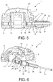
figure 6 shows the assembly infigure 4 in cross-section and in separate parts; - . -
figure 7 shows in an axonometric view the assembly infigure 1 sectioned substantially in the centreline along a tangential plane parallel to the braking surfaces of the disc and with the components of the connection between the parking caliper and the fixed caliper body in separate parts; - . -
figure 8 shows, in an axonometric view from the wheel side, the assembly infigure 1 with the connection between the parking caliper and fixed caliper body in separate parts; - . -
figure 9 shows, in an axonometric view from the wheel side, the assembly infigure 1 ; - . -
figure 10 shows a view from above of the assembly infigure 1 ; - . -
figure 11 shows a front view from the vehicle side of the assembly infigure 1 ; - . -
figure 12 shows a front view from the wheel side of the assembly infigure 1 ; - . -
figure 13 shows a cross-section along a tangential plane passing through the centreline of the assembly infigure 1 ; - . -
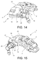
Figures 14 and 15 show in an axonometric view a service and parking caliper assembly respectively on the vehicle and wheel sides, in which an electrical type of actuation is connected to the parking caliper; - . -
figure 16 shows a cross-section according to an axial radial plane of the parking caliper; - . -
figure 17 shows a cross-section along a tangential plane of the centreline of the parking caliper; - . -
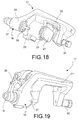
figure 18 shows, in an axonometric view from the wheel side, the parking caliper; - . -
figure 19 shows, in an axonometric view from the vehicle side, the parking caliper without pads; - . -
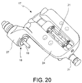
figure 20 shows, in an axonometric view from above, the parking caliper infigure 18 . - . With reference to the aforementioned figures, a caliper assembly for a service and
parking disc brake 1 comprises aservice caliper body 2 placed astride a disc for adisc brake 3. - .
Said body 2 comprises a first elongated element on thevehicle side 4 suitable for facing afirst braking surface 5 of thebrake disc 3. - . Said first elongated
element 4 comprises at least afirst cylinder 6 which houses afirst thrust piston 7 suitable for exercising a thrust action on a facingfirst service pad 8 to abut it against afirst braking surface 5 of thedisc 3 and exercise a service braking action on the vehicle. - . In accordance with an embodiment, said first
elongated element 4 comprises at least a first abutment and guidepin 16 of thefirst pad 8 to guide saidpad 8 and receive the braking action of the vehicle. - . In accordance with an embodiment, said
service caliper body 2 further comprises a second elongated element on thewheel side 9 suitable for facing asecond braking surface 10 of thebrake disc 3. - . Said second
elongated element 9 comprises at least asecond cylinder 11 which houses asecond thrust piston 12 suitable for exercising a thrust action on a facingsecond service pad 13 to abut it against a second braking surface 14 of thedisc 3 and exercise a service braking action on the vehicle. - . In accordance with an embodiment, said
service caliper body 2 comprises, in addition, at least afirst bridge 15 suitable for connecting said first elongated element on thevehicle side 4 to said second elongated element on thewheel side 9. - . In accordance with an embodiment, said
assembly 1 further comprises aparking caliper 17 comprising separate thrust means 20 of the parking caliper distinct from said first andsecond cylinder third parking pad 21 against thefirst braking surface 5 of thedisc 3. - . In accordance with an embodiment, said
parking caliper 17 has aconnection 18 for supporting and connecting at least partially saidparking caliper 17 to saidservice caliper body 2. - . In accordance with an embodiment, said
connection 18 of theparking caliper 17 to theservice caliper body 2 comprises a first blockingscrew 19 positioned coaxially to said first support and guidepin 16 of thefirst service pad 8. - . In accordance with an embodiment, said
service caliper body 2 comprises at least twobridges disc 23. - . In accordance with an embodiment, said
parking caliper 17 is positioned between said twoadjacent bridges - . In accordance with an embodiment, said
parking caliper 17 is a floating parking caliper comprising a floatingbody 24, for example, but not necessarily, in a single piece or alternatively in two separable pieces firmly connected to each other, which moves by sliding onguides service caliper body 2 which acts as a bracket for said floatingbody 24. - . In accordance with an embodiment, said first blocking screw acts as a
first guide 19 of said floatingbody 24. - . In accordance with an embodiment, a
guide bush 26 suitable for receiving the floatingbody 24 is fitted onto said first blockingscrew 19. - . In accordance with an embodiment, said
guide bush 26 receives, in such a way as to be free to slide, anattachment portion 27 of the floatingbody 24. - . In accordance with an embodiment, said
parking caliper 17 comprises a floatingcaliper body 24 supported in a sliding manner on saidservice caliper body 2 which acts as a bracket for said floatingbody 24. - . In accordance with an embodiment, said floating
body 24 slides on asecond guide 25 placed on the opposite side of the floatingbody 24 in relation to thefirst guide 19 comprising said blocking screw. - . In accordance with an embodiment, said
second guide 25 is connected to the elongated element on thewheel side 9 of theservice caliper body 2. - . In accordance with an embodiment, said first abutment and guide
pin 16 of thefirst pad 8 has astem 28 eternally threaded and housed in a threadedseat 29 provided in the first elongated element on thewheel side 4. - . In accordance with an embodiment, said abutment and guide
pin 16 of thefirst pad 8 has a hollow and internally threadedstem 28 to house a threadedend 30 of the first blockingscrew 19. - . In accordance with an embodiment, said first blocking
screw 19 has a stem which projects so as to overhang from said first elongated element on thevehicle side 4 to form a sliding guide for the floatingbody 24 of theparking caliper 17. - . In accordance with an embodiment, a
guide bush 26 protected bydust covers 31 is positioned between the floatingbody 24 and the first blockingscrew 19. - . Obviously, a person skilled in the art may make numerous modifications and variations to the brake caliper body according to the invention so as to satisfy contingent and specific requirements while remaining within the scope of the invention as defined by the following claims.
REFERENCES 1. assembly 26. sliding bush on first blocking screw 2. service caliper body 27. attachment portion of the floating body to the bush 3. disc for disc brake 28. stem of first pad guide pin 4. elongated element vehicle side 29. threaded seat for pin stem 5. first braking surface vehicle side of disc 30. threaded end of first blocking screw 6. first cylinder 31. dust cover 7. first piston 8. first pad 9. second elongated element wheel side 10. second braking surface 11. second cylinder 12. second thrust piston 13. second service pad 14. second braking surface 15. first bridge 16. first pad guide abutment pin 17. parking caliper 18. connection 19. first blocking screw 20. separate parking thrust means 21. third parking pad 22. second bridge adjacent to service caliper body 23. window between bridges 24. floating body parking caliper 25. second floating body sliding guide
Claims (7)
- Assembly of service and parking calliper for disc brake (1) comprising:- a service calliper body (2) arranged astride of a disc for disc brake (3) having a first vehicle side elongated element (4) suitable for facing a first braking surface (5) of the brake disc (3), said first elongated element (4) comprising at least a first cylinder (6) housing a first thrust piston (7) suitable for exerting a thrust action of a faced first service pad (8) for abutting it against a first braking surface (5) of the disc (3) and exerting a service braking action of the vehicle;- said first elongated element (4) comprising at least a first abutment and guide pivot or pin (16) of the first pad (8) for guiding it and receiving the braking action of the vehicle;- said service calliper body (2) further comprising a second wheel side elongated element (9) suitable for facing a second braking surface (10) of the brake disc (3), said second elongated element (9) comprising at least a second cylinder (11) housing a second thrust piston (12) suitable for exerting a thrust action on a second faced service pad (13) for abutting it against a second braking surface (14) of the disc (3) and exerting a service braking action of the vehicle;- said service calliper body (2) further comprises at least a first bridge (15) suitable for connecting said first vehicle side elongated element (4) to said second wheel side elongated element (9);said assembly (1) further comprises:- a parking calliper (17) comprising separated thrust means (20) of the parking calliper separated from said first and second cylinder (6, 11) and suitable for abutting at least a third parking pad (21) against the first braking surface (5) of the disc (3);- said parking calliper (17) has a connection (18) for connecting and supporting at least partially said parking calliper (17) to said service calliper body (2);characterised in that- said connection (18) of the parking calliper (17) to the service calliper body (2) comprises a first locking screw (19) arranged coaxially to said first pin (16) for supporting and guiding the first service pad (8).
- Assembly (1) according to claim 1, wherein said service calliper body (2) comprises at least two bridges (15, 22) arranged adjacent to one another leaving between them a window for accessing the disc (23), and/or wherein
said parking calliper (17) is arranged between said adjacent bridges (15, 22). - Assembly (1) according to any one of the previous claims, wherein said parking calliper (17) is a floating parking calliper comprising a floating body (24), in a single piece or in two pieces firmly connected to one another, which moves sliding on rails (19, 25) fastened to the service calliper body (2) serving as a bracket for said floating body (24).
- Assembly (1) according to claim 3, wherein said first locking screw (19) serves as a first rail (19) of said floating body (24), and/or wherein
on said first locking screw (19) a guiding bush (26) suitable for receiving the floating body (24) is put on, and/or wherein
said guiding bush (26) receives an attachment portion (27) of the floating body (24), which is free to slide. - Assembly (1) according to any one of the previous claims, wherein
said parking calliper (17) comprises a floating calliper body (24) slidably supported on said service calliper body (2) serving as a bracket for said floating body (24), wherein said floating body (24) slides on a second rail (25) arranged on the opposite side of the floating body (24) with respect to the first rail (19) comprising said locking screw (19), and/or wherein
said second rail (25) is connected to the wheel side elongated element (9) of the service calliper body (2). - Assembly (1) according to any one of the previous claims, wherein
said first abutment and guide pivot or pin (16) of the first pad (8) has an externally threaded stem (28) received in a threaded seat (29) provided in the first vehicle side elongated element (4), and/or wherein
said abutment and guide pin (16) of the first pad (8) has a hollow stem (28) internally threaded for housing a threaded end (30) of the first locking screw (19). - Assembly (1) according to one of the previous claims, wherein
said first locking screw (19) has a stem projecting cantilevered from said first vehicle side elongated element (4) to form a sliding rail for the floating body (24) of the parking calliper (17), and/or wherein
between the floating body (24) and the first locking screw (19) a guiding bush (26), protected by anti-dust caps (31), is interposed.
Applications Claiming Priority (2)
| Application Number | Priority Date | Filing Date | Title |
|---|---|---|---|
| IT000232A ITMI20120232A1 (en) | 2012-02-16 | 2012-02-16 | ASSEMBLY OF SERVICE CLAMP AND STATION |
| PCT/IB2013/051248 WO2013121395A1 (en) | 2012-02-16 | 2013-02-15 | Caliper assembly for service and parking disc brake |
Publications (2)
| Publication Number | Publication Date |
|---|---|
| EP2815147A1 EP2815147A1 (en) | 2014-12-24 |
| EP2815147B1 true EP2815147B1 (en) | 2016-05-11 |
Family
ID=45998578
Family Applications (1)
| Application Number | Title | Priority Date | Filing Date |
|---|---|---|---|
| EP13716391.1A Active EP2815147B1 (en) | 2012-02-16 | 2013-02-15 | Caliper assembly for service and parking disc brake |
Country Status (5)
| Country | Link |
|---|---|
| US (1) | US9422991B2 (en) |
| EP (1) | EP2815147B1 (en) |
| CN (1) | CN104246273B (en) |
| IT (1) | ITMI20120232A1 (en) |
| WO (1) | WO2013121395A1 (en) |
Families Citing this family (28)
| Publication number | Priority date | Publication date | Assignee | Title |
|---|---|---|---|---|
| US9353811B2 (en) | 2013-11-13 | 2016-05-31 | Akebono Brake Industry Co., Ltd | Electric park brake for a multiple piston caliper |
| JP2015124811A (en) * | 2013-12-26 | 2015-07-06 | 曙ブレーキ工業株式会社 | Disc brake device |
| JP2015124812A (en) * | 2013-12-26 | 2015-07-06 | 曙ブレーキ工業株式会社 | Disc brake device |
| JP6208065B2 (en) * | 2014-03-31 | 2017-10-04 | 曙ブレーキ工業株式会社 | Opposite piston type disc brake device |
| JP2015215074A (en) * | 2014-05-13 | 2015-12-03 | 曙ブレーキ工業株式会社 | Disc brake device |
| JP2016017558A (en) * | 2014-07-08 | 2016-02-01 | 曙ブレーキ工業株式会社 | Disc brake device |
| USD790417S1 (en) * | 2014-08-05 | 2017-06-27 | Freni Brembo S.P.A. | Disc brake calliper body |
| CN107002783B (en) * | 2014-11-28 | 2019-10-15 | 福乐尼·乐姆宝公开有限公司 | Brake disc floating calipers for service and parking brakes |
| JP6446275B2 (en) * | 2015-01-19 | 2018-12-26 | 曙ブレーキ工業株式会社 | Counter-piston disc brake caliper |
| DE102015107128A1 (en) | 2015-05-07 | 2016-11-10 | Knorr-Bremse Systeme für Nutzfahrzeuge GmbH | Disc brake of a commercial vehicle |
| USD785520S1 (en) * | 2015-07-20 | 2017-05-02 | Freni Brembo S.P.A. | Disc brake calliper |
| USD812534S1 (en) * | 2015-09-11 | 2018-03-13 | Hb Performance Systems, Inc. | Brake caliper housing |
| TWI616603B (en) * | 2016-05-20 | 2018-03-01 | Tw Racing Parts Inc | Electronic parking calipers |
| TWM530777U (en) * | 2016-07-26 | 2016-10-21 | Jieh Jia Entpr Co Ltd | Electronic brake calipers |
| JP6414992B2 (en) * | 2016-09-29 | 2018-10-31 | 本田技研工業株式会社 | Rear wheel brake device for vehicle |
| USD864062S1 (en) * | 2017-04-13 | 2019-10-22 | Freni Brembo S.P.A. | Disc brake caliper |
| JP1603869S (en) * | 2017-04-13 | 2018-05-14 | ||
| US10458499B2 (en) | 2017-10-20 | 2019-10-29 | Akebono Brake Industry Co., Ltd. | Multi-caliper brake assembly per rotor |
| KR102020664B1 (en) * | 2017-12-18 | 2019-09-11 | 스톨츠 주식회사 | Caliper band |
| IT201800006539A1 (en) * | 2018-06-21 | 2019-12-21 | DISC BRAKE CALIPER | |
| USD902097S1 (en) * | 2018-10-15 | 2020-11-17 | Wooshin Industries Co., Ltd. | Disk brake caliper for automobile |
| US11339842B2 (en) | 2019-03-26 | 2022-05-24 | Akebono Brake Industry Co., Ltd. | Brake system with torque distributing assembly |
| CN112413006B (en) * | 2019-08-23 | 2022-02-08 | 比亚迪股份有限公司 | Disc brake and vehicle |
| EP3835612B1 (en) | 2019-12-10 | 2022-08-24 | ZF CV Systems Europe BV | Disc brake, especially for commercial vehicles and vehicle comprising a disc brake, especially a commercial vehicle comprising a disc brake |
| DE102021110963B3 (en) | 2021-04-28 | 2022-12-01 | Schaeffler Technologies AG & Co. KG | Disc brake system with parking brake module for a vehicle and vehicle with the disc brake system |
| EP4652382A1 (en) * | 2023-01-18 | 2025-11-26 | Hendrickson USA, L.L.C. | Shear-to-torque guide pin assembly for heavy-duty vehicles |
| KR20240171415A (en) * | 2023-05-30 | 2024-12-09 | 현대모비스 주식회사 | Brake device and vehicle having the same |
| DE102023209445A1 (en) * | 2023-09-27 | 2025-03-27 | Hl Mando Corporation | CALIPER BRAKE |
Family Cites Families (8)
| Publication number | Priority date | Publication date | Assignee | Title |
|---|---|---|---|---|
| CH394834A (en) | 1962-12-07 | 1965-06-30 | Campagnolo Tullio | Disc brake for motor vehicles in general with hydraulic and mechanical actuation |
| GB2182990B (en) * | 1985-11-15 | 1989-09-27 | Nippon Air Brake Co | Disc brake |
| US4784241A (en) | 1986-09-26 | 1988-11-15 | Allied-Signal Inc. | Integrated disc brake and drum rake construction |
| US4793447A (en) | 1986-12-23 | 1988-12-27 | Allied-Signal Inc. | Electrically operated disc brake |
| FR2638498B1 (en) * | 1988-10-28 | 1993-04-09 | Bendix France | BRAKE WITH TWO FIXED GAP DISCS |
| AUPR688801A0 (en) | 2001-08-08 | 2001-08-30 | Pbr Australia Pty Ltd | Disc brake caliper |
| DE602005014020D1 (en) * | 2005-10-05 | 2009-05-28 | Freni Brembo Spa | DISC BRAKING SYSTEM FOR A VEHICLE COMBINING OPERATOR AND PARKING BRAKE |
| DE102008034300A1 (en) * | 2008-07-23 | 2010-01-28 | Lucas Automotive Gmbh | Vehicle disc brake |
-
2012
- 2012-02-16 IT IT000232A patent/ITMI20120232A1/en unknown
-
2013
- 2013-02-15 WO PCT/IB2013/051248 patent/WO2013121395A1/en not_active Ceased
- 2013-02-15 CN CN201380020192.6A patent/CN104246273B/en active Active
- 2013-02-15 EP EP13716391.1A patent/EP2815147B1/en active Active
- 2013-02-15 US US14/379,238 patent/US9422991B2/en active Active
Also Published As
| Publication number | Publication date |
|---|---|
| WO2013121395A1 (en) | 2013-08-22 |
| EP2815147A1 (en) | 2014-12-24 |
| US9422991B2 (en) | 2016-08-23 |
| CN104246273B (en) | 2016-12-14 |
| CN104246273A (en) | 2014-12-24 |
| ITMI20120232A1 (en) | 2013-08-17 |
| US20150021125A1 (en) | 2015-01-22 |
Similar Documents
| Publication | Publication Date | Title |
|---|---|---|
| US9422991B2 (en) | Caliper assembly for service and parking disc brake | |
| EP2815146B1 (en) | Parking caliper assembly | |
| US10738844B2 (en) | Disc brake for a utility vehicle | |
| EP3129672B2 (en) | Disc brake pad, spring for disc brake caliper and disk brake caliper assembly | |
| US5343985A (en) | Floating-caliper spot-type disc brake for high-powered vehicles | |
| EP3676508B1 (en) | Brake disc assembly | |
| US8307961B2 (en) | Rail vehicle brake slack adjuster | |
| US20140097050A1 (en) | Floating calliper for disc brake | |
| US6173819B1 (en) | Partially lined disc brake | |
| WO2009014022A4 (en) | Vehicle disc brake device | |
| KR20150121075A (en) | Disc brake assembly with non-rotatable vehicle component and method for producing same | |
| ATE428870T1 (en) | DISC BRAKE SYSTEM FOR A VEHICLE WHICH COMBINES OPERATING AND PARKING BRAKES | |
| US20140083805A1 (en) | Disc brake caliper, brake pads and pad pin | |
| US7331430B2 (en) | Multi-disc brake with fixed center brake pad assembly | |
| EP1963701B1 (en) | Disc brake caliper | |
| US7234568B2 (en) | High performance disk brake | |
| CN210686773U (en) | Double-cylinder disc brake | |
| JP2015004412A (en) | Electric parking brake and disc brake with parking brake | |
| KR20190030264A (en) | Monoblock caliper brake | |
| ITPD20120214A1 (en) | BRAKE CALIPER WITH DISC | |
| US11215248B2 (en) | Floating-caliper disc brake | |
| CN214036595U (en) | Brake drum device for load-carrying truck | |
| EP1249387A2 (en) | Fore-end assembly with improved shock absorbing means for motorcycles | |
| CN221195833U (en) | Mounting structure of multi-piston brake caliper for portable vehicle | |
| GB2126294A (en) | Spot-type disc brake |
Legal Events
| Date | Code | Title | Description |
|---|---|---|---|
| PUAI | Public reference made under article 153(3) epc to a published international application that has entered the european phase |
Free format text: ORIGINAL CODE: 0009012 |
|
| 17P | Request for examination filed |
Effective date: 20140814 |
|
| AK | Designated contracting states |
Kind code of ref document: A1 Designated state(s): AL AT BE BG CH CY CZ DE DK EE ES FI FR GB GR HR HU IE IS IT LI LT LU LV MC MK MT NL NO PL PT RO RS SE SI SK SM TR |
|
| AX | Request for extension of the european patent |
Extension state: BA ME |
|
| DAX | Request for extension of the european patent (deleted) | ||
| GRAP | Despatch of communication of intention to grant a patent |
Free format text: ORIGINAL CODE: EPIDOSNIGR1 |
|
| INTG | Intention to grant announced |
Effective date: 20151126 |
|
| GRAS | Grant fee paid |
Free format text: ORIGINAL CODE: EPIDOSNIGR3 |
|
| GRAA | (expected) grant |
Free format text: ORIGINAL CODE: 0009210 |
|
| AK | Designated contracting states |
Kind code of ref document: B1 Designated state(s): AL AT BE BG CH CY CZ DE DK EE ES FI FR GB GR HR HU IE IS IT LI LT LU LV MC MK MT NL NO PL PT RO RS SE SI SK SM TR |
|
| REG | Reference to a national code |
Ref country code: GB Ref legal event code: FG4D |
|
| REG | Reference to a national code |
Ref country code: CH Ref legal event code: EP |
|
| REG | Reference to a national code |
Ref country code: AT Ref legal event code: REF Ref document number: 798923 Country of ref document: AT Kind code of ref document: T Effective date: 20160515 |
|
| REG | Reference to a national code |
Ref country code: IE Ref legal event code: FG4D |
|
| REG | Reference to a national code |
Ref country code: DE Ref legal event code: R096 Ref document number: 602013007438 Country of ref document: DE |
|
| REG | Reference to a national code |
Ref country code: LT Ref legal event code: MG4D |
|
| REG | Reference to a national code |
Ref country code: NL Ref legal event code: MP Effective date: 20160511 |
|
| PG25 | Lapsed in a contracting state [announced via postgrant information from national office to epo] |
Ref country code: NL Free format text: LAPSE BECAUSE OF FAILURE TO SUBMIT A TRANSLATION OF THE DESCRIPTION OR TO PAY THE FEE WITHIN THE PRESCRIBED TIME-LIMIT Effective date: 20160511 Ref country code: FI Free format text: LAPSE BECAUSE OF FAILURE TO SUBMIT A TRANSLATION OF THE DESCRIPTION OR TO PAY THE FEE WITHIN THE PRESCRIBED TIME-LIMIT Effective date: 20160511 Ref country code: NO Free format text: LAPSE BECAUSE OF FAILURE TO SUBMIT A TRANSLATION OF THE DESCRIPTION OR TO PAY THE FEE WITHIN THE PRESCRIBED TIME-LIMIT Effective date: 20160811 Ref country code: LT Free format text: LAPSE BECAUSE OF FAILURE TO SUBMIT A TRANSLATION OF THE DESCRIPTION OR TO PAY THE FEE WITHIN THE PRESCRIBED TIME-LIMIT Effective date: 20160511 |
|
| REG | Reference to a national code |
Ref country code: AT Ref legal event code: MK05 Ref document number: 798923 Country of ref document: AT Kind code of ref document: T Effective date: 20160511 |
|
| PG25 | Lapsed in a contracting state [announced via postgrant information from national office to epo] |
Ref country code: GR Free format text: LAPSE BECAUSE OF FAILURE TO SUBMIT A TRANSLATION OF THE DESCRIPTION OR TO PAY THE FEE WITHIN THE PRESCRIBED TIME-LIMIT Effective date: 20160812 Ref country code: LV Free format text: LAPSE BECAUSE OF FAILURE TO SUBMIT A TRANSLATION OF THE DESCRIPTION OR TO PAY THE FEE WITHIN THE PRESCRIBED TIME-LIMIT Effective date: 20160511 Ref country code: SE Free format text: LAPSE BECAUSE OF FAILURE TO SUBMIT A TRANSLATION OF THE DESCRIPTION OR TO PAY THE FEE WITHIN THE PRESCRIBED TIME-LIMIT Effective date: 20160511 Ref country code: RS Free format text: LAPSE BECAUSE OF FAILURE TO SUBMIT A TRANSLATION OF THE DESCRIPTION OR TO PAY THE FEE WITHIN THE PRESCRIBED TIME-LIMIT Effective date: 20160511 Ref country code: HR Free format text: LAPSE BECAUSE OF FAILURE TO SUBMIT A TRANSLATION OF THE DESCRIPTION OR TO PAY THE FEE WITHIN THE PRESCRIBED TIME-LIMIT Effective date: 20160511 Ref country code: PT Free format text: LAPSE BECAUSE OF FAILURE TO SUBMIT A TRANSLATION OF THE DESCRIPTION OR TO PAY THE FEE WITHIN THE PRESCRIBED TIME-LIMIT Effective date: 20160912 Ref country code: ES Free format text: LAPSE BECAUSE OF FAILURE TO SUBMIT A TRANSLATION OF THE DESCRIPTION OR TO PAY THE FEE WITHIN THE PRESCRIBED TIME-LIMIT Effective date: 20160511 |
|
| PG25 | Lapsed in a contracting state [announced via postgrant information from national office to epo] |
Ref country code: SK Free format text: LAPSE BECAUSE OF FAILURE TO SUBMIT A TRANSLATION OF THE DESCRIPTION OR TO PAY THE FEE WITHIN THE PRESCRIBED TIME-LIMIT Effective date: 20160511 Ref country code: RO Free format text: LAPSE BECAUSE OF FAILURE TO SUBMIT A TRANSLATION OF THE DESCRIPTION OR TO PAY THE FEE WITHIN THE PRESCRIBED TIME-LIMIT Effective date: 20160511 Ref country code: DK Free format text: LAPSE BECAUSE OF FAILURE TO SUBMIT A TRANSLATION OF THE DESCRIPTION OR TO PAY THE FEE WITHIN THE PRESCRIBED TIME-LIMIT Effective date: 20160511 Ref country code: CZ Free format text: LAPSE BECAUSE OF FAILURE TO SUBMIT A TRANSLATION OF THE DESCRIPTION OR TO PAY THE FEE WITHIN THE PRESCRIBED TIME-LIMIT Effective date: 20160511 Ref country code: EE Free format text: LAPSE BECAUSE OF FAILURE TO SUBMIT A TRANSLATION OF THE DESCRIPTION OR TO PAY THE FEE WITHIN THE PRESCRIBED TIME-LIMIT Effective date: 20160511 |
|
| REG | Reference to a national code |
Ref country code: DE Ref legal event code: R097 Ref document number: 602013007438 Country of ref document: DE |
|
| PG25 | Lapsed in a contracting state [announced via postgrant information from national office to epo] |
Ref country code: PL Free format text: LAPSE BECAUSE OF FAILURE TO SUBMIT A TRANSLATION OF THE DESCRIPTION OR TO PAY THE FEE WITHIN THE PRESCRIBED TIME-LIMIT Effective date: 20160511 Ref country code: AT Free format text: LAPSE BECAUSE OF FAILURE TO SUBMIT A TRANSLATION OF THE DESCRIPTION OR TO PAY THE FEE WITHIN THE PRESCRIBED TIME-LIMIT Effective date: 20160511 Ref country code: BE Free format text: LAPSE BECAUSE OF FAILURE TO SUBMIT A TRANSLATION OF THE DESCRIPTION OR TO PAY THE FEE WITHIN THE PRESCRIBED TIME-LIMIT Effective date: 20160511 Ref country code: SM Free format text: LAPSE BECAUSE OF FAILURE TO SUBMIT A TRANSLATION OF THE DESCRIPTION OR TO PAY THE FEE WITHIN THE PRESCRIBED TIME-LIMIT Effective date: 20160511 |
|
| PLBE | No opposition filed within time limit |
Free format text: ORIGINAL CODE: 0009261 |
|
| STAA | Information on the status of an ep patent application or granted ep patent |
Free format text: STATUS: NO OPPOSITION FILED WITHIN TIME LIMIT |
|
| 26N | No opposition filed |
Effective date: 20170214 |
|
| PG25 | Lapsed in a contracting state [announced via postgrant information from national office to epo] |
Ref country code: SI Free format text: LAPSE BECAUSE OF FAILURE TO SUBMIT A TRANSLATION OF THE DESCRIPTION OR TO PAY THE FEE WITHIN THE PRESCRIBED TIME-LIMIT Effective date: 20160511 |
|
| PG25 | Lapsed in a contracting state [announced via postgrant information from national office to epo] |
Ref country code: MC Free format text: LAPSE BECAUSE OF FAILURE TO SUBMIT A TRANSLATION OF THE DESCRIPTION OR TO PAY THE FEE WITHIN THE PRESCRIBED TIME-LIMIT Effective date: 20160511 |
|
| REG | Reference to a national code |
Ref country code: CH Ref legal event code: PL |
|
| GBPC | Gb: european patent ceased through non-payment of renewal fee |
Effective date: 20170215 |
|
| PG25 | Lapsed in a contracting state [announced via postgrant information from national office to epo] |
Ref country code: CH Free format text: LAPSE BECAUSE OF NON-PAYMENT OF DUE FEES Effective date: 20170228 Ref country code: LI Free format text: LAPSE BECAUSE OF NON-PAYMENT OF DUE FEES Effective date: 20170228 |
|
| REG | Reference to a national code |
Ref country code: IE Ref legal event code: MM4A |
|
| REG | Reference to a national code |
Ref country code: FR Ref legal event code: ST Effective date: 20171031 |
|
| PG25 | Lapsed in a contracting state [announced via postgrant information from national office to epo] |
Ref country code: LU Free format text: LAPSE BECAUSE OF NON-PAYMENT OF DUE FEES Effective date: 20170215 |
|
| PG25 | Lapsed in a contracting state [announced via postgrant information from national office to epo] |
Ref country code: FR Free format text: LAPSE BECAUSE OF NON-PAYMENT OF DUE FEES Effective date: 20170228 |
|
| PG25 | Lapsed in a contracting state [announced via postgrant information from national office to epo] |
Ref country code: GB Free format text: LAPSE BECAUSE OF NON-PAYMENT OF DUE FEES Effective date: 20170215 Ref country code: IE Free format text: LAPSE BECAUSE OF NON-PAYMENT OF DUE FEES Effective date: 20170215 |
|
| PG25 | Lapsed in a contracting state [announced via postgrant information from national office to epo] |
Ref country code: MT Free format text: LAPSE BECAUSE OF NON-PAYMENT OF DUE FEES Effective date: 20170215 |
|
| PG25 | Lapsed in a contracting state [announced via postgrant information from national office to epo] |
Ref country code: AL Free format text: LAPSE BECAUSE OF FAILURE TO SUBMIT A TRANSLATION OF THE DESCRIPTION OR TO PAY THE FEE WITHIN THE PRESCRIBED TIME-LIMIT Effective date: 20160511 |
|
| PG25 | Lapsed in a contracting state [announced via postgrant information from national office to epo] |
Ref country code: HU Free format text: LAPSE BECAUSE OF FAILURE TO SUBMIT A TRANSLATION OF THE DESCRIPTION OR TO PAY THE FEE WITHIN THE PRESCRIBED TIME-LIMIT; INVALID AB INITIO Effective date: 20130215 |
|
| PG25 | Lapsed in a contracting state [announced via postgrant information from national office to epo] |
Ref country code: BG Free format text: LAPSE BECAUSE OF FAILURE TO SUBMIT A TRANSLATION OF THE DESCRIPTION OR TO PAY THE FEE WITHIN THE PRESCRIBED TIME-LIMIT Effective date: 20160511 |
|
| PG25 | Lapsed in a contracting state [announced via postgrant information from national office to epo] |
Ref country code: CY Free format text: LAPSE BECAUSE OF FAILURE TO SUBMIT A TRANSLATION OF THE DESCRIPTION OR TO PAY THE FEE WITHIN THE PRESCRIBED TIME-LIMIT Effective date: 20160511 |
|
| PG25 | Lapsed in a contracting state [announced via postgrant information from national office to epo] |
Ref country code: MK Free format text: LAPSE BECAUSE OF FAILURE TO SUBMIT A TRANSLATION OF THE DESCRIPTION OR TO PAY THE FEE WITHIN THE PRESCRIBED TIME-LIMIT Effective date: 20160511 |
|
| PG25 | Lapsed in a contracting state [announced via postgrant information from national office to epo] |
Ref country code: TR Free format text: LAPSE BECAUSE OF FAILURE TO SUBMIT A TRANSLATION OF THE DESCRIPTION OR TO PAY THE FEE WITHIN THE PRESCRIBED TIME-LIMIT Effective date: 20160511 |
|
| PG25 | Lapsed in a contracting state [announced via postgrant information from national office to epo] |
Ref country code: IS Free format text: LAPSE BECAUSE OF FAILURE TO SUBMIT A TRANSLATION OF THE DESCRIPTION OR TO PAY THE FEE WITHIN THE PRESCRIBED TIME-LIMIT Effective date: 20160911 |
|
| REG | Reference to a national code |
Ref country code: DE Ref legal event code: R081 Ref document number: 602013007438 Country of ref document: DE Owner name: BREMBO S.P.A., CURNO, IT Free format text: FORMER OWNER: FRENI BREMBO S.P.A., CURNO, BERGAMO, IT |
|
| P01 | Opt-out of the competence of the unified patent court (upc) registered |
Effective date: 20230526 |
|
| PGFP | Annual fee paid to national office [announced via postgrant information from national office to epo] |
Ref country code: DE Payment date: 20260223 Year of fee payment: 14 |
|
| PGFP | Annual fee paid to national office [announced via postgrant information from national office to epo] |
Ref country code: IT Payment date: 20260223 Year of fee payment: 14 |