EP2814635B1 - Locating tool, in particular for a sliding rod end or an aircraft landing gear casing - Google Patents
Locating tool, in particular for a sliding rod end or an aircraft landing gear casing Download PDFInfo
- Publication number
- EP2814635B1 EP2814635B1 EP13749669.1A EP13749669A EP2814635B1 EP 2814635 B1 EP2814635 B1 EP 2814635B1 EP 13749669 A EP13749669 A EP 13749669A EP 2814635 B1 EP2814635 B1 EP 2814635B1
- Authority
- EP
- European Patent Office
- Prior art keywords
- flange
- locating
- locating tool
- clamping
- head
- Prior art date
- Legal status (The legal status is an assumption and is not a legal conclusion. Google has not performed a legal analysis and makes no representation as to the accuracy of the status listed.)
- Active
Links
- 238000003754 machining Methods 0.000 description 5
- 230000004807 localization Effects 0.000 description 3
- 239000011248 coating agent Substances 0.000 description 1
- 238000000576 coating method Methods 0.000 description 1
- 230000000694 effects Effects 0.000 description 1
- 238000009434 installation Methods 0.000 description 1
- 230000035515 penetration Effects 0.000 description 1
Images

Classifications
-
- B—PERFORMING OPERATIONS; TRANSPORTING
- B64—AIRCRAFT; AVIATION; COSMONAUTICS
- B64F—GROUND OR AIRCRAFT-CARRIER-DECK INSTALLATIONS SPECIALLY ADAPTED FOR USE IN CONNECTION WITH AIRCRAFT; DESIGNING, MANUFACTURING, ASSEMBLING, CLEANING, MAINTAINING OR REPAIRING AIRCRAFT, NOT OTHERWISE PROVIDED FOR; HANDLING, TRANSPORTING, TESTING OR INSPECTING AIRCRAFT COMPONENTS, NOT OTHERWISE PROVIDED FOR
- B64F5/00—Designing, manufacturing, assembling, cleaning, maintaining or repairing aircraft, not otherwise provided for; Handling, transporting, testing or inspecting aircraft components, not otherwise provided for
- B64F5/10—Manufacturing or assembling aircraft, e.g. jigs therefor
Landscapes
- Engineering & Computer Science (AREA)
- Manufacturing & Machinery (AREA)
- Transportation (AREA)
- Aviation & Aerospace Engineering (AREA)
- Jigs For Machine Tools (AREA)
- Shafts, Cranks, Connecting Bars, And Related Bearings (AREA)
Description
L'invention est relative à un outillage de localisation pouvant être utilisé notamment pour localiser une tige coulissante ou de caisson d'atterrisseur d'aéronef sur un gabarit d'usinage ou de montage.The invention relates to a locating tool that can be used in particular for locating a sliding rod or aircraft landing gear box on a machining or mounting jig.
On sait que les tiges coulissantes ou les caissons d'atterrisseurs comportent bien souvent des extrémités en T. Les tiges coulissantes peuvent par exemple comporter à leur extrémité inférieure un essieu réalisé intégralement avec le corps de la tige destiné à recevoir des roues, tandis que les caissons peuvent comporter à leur extrémité supérieure une traverse également réalisée intégralement avec le corps du caisson pour recevoir à ses extrémités les pivots d'articulation de l'atterrisseur sur l'aéronef.It is known that the sliding rods or the landing gear housings often have T-shaped ends. The sliding rods may for example comprise, at their lower end, an axle integrally formed with the body of the rod intended to receive wheels. caissons may comprise at their upper end a crossbar also made integrally with the body of the box to receive at its ends the hinge pins of the landing gear on the aircraft.
Il importe de pouvoir disposer à la jonction entre le corps de la pièce et la portion transversale (essieu, traverse) un outillage de localisation pour pouvoir recevoir la pièce dans un gabarit d'usinage, par exemple pour procéder aux usinages de finition du corps (notamment le revêtement et la rectification externe ou interne du corps de la pièce). En général, la pièce comporte un alésage dans la paroi de la portion transversale, s'étendant dans l'axe du corps de la pièce.It is important to have at the junction between the body of the part and the transverse portion (axle, crossbeam) a location tool to be able to receive the workpiece in a machining jig, for example to carry out finishing machining of the body ( in particular coating and external or internal grinding of the body of the part). In general, the part has a bore in the wall of the transverse portion, extending in the axis of the body of the part.
L'outillage de localisation classiquement utilisé est un centreur qui comporte un organe de centrage qui est rapporté sur la pièce pour saillir de celle-ci et ainsi permettre le positionnement de la pièce sur un gabarit d'usinage ou de montage.The location tooling conventionally used is a centraliser which comprises a centering member which is attached to the part to project from it and thus allow the positioning of the part on a machining or assembly template.
Pour ce faire, l'organe de centrage du centreur comporte une portée terminée qui est introduite dans l'alésage de la pièce. La portée est introduite dans l'alésage jusqu'à ce qu'un épaulement du centreur vienne buter contre une face externe de la pièce. Le centreur est maintenu en position sur la pièce au moyen d'une bride qui s'étend contre la face interne de la pièce, de l'autre côté de la face externe de la pièce, et qui est serrée au moyen d'une tige ayant une tête portant sur la bride, et qui traverse l'organe de centrage pour recevoir un écrou de serrage.To do this, the centraliser of the centraliser comprises a finished scope which is inserted into the bore of the piece. The scope is introduced into the bore until a shoulder of the centraliser abuts against an outer face of the part. The centering device is held in position on the part by means of a flange which extends against the internal face of the part, on the other side of the outer face of the part, and which is tightened by means of a rod having a head bearing on the flange, and which passes through the centering member to receive a clamping nut.
Un problème parfois rencontré est que la face interne de la pièce n'est pas parallèle à sa face externe. On pourrait alors prévoir une bride à face d'appui oblique faisant un angle adéquat avec la face externe de la pièce. Cependant, il est très difficile de contrôler l'orientation de la bride lors du serrage, puisque le centreur obstrue complètement l'alésage. En outre, une telle bride ne peut être utilisée que pour un seul type d'angle.A problem sometimes encountered is that the inner face of the part is not parallel to its outer face. One could then provide a flange with oblique bearing face at a suitable angle with the outer face of the part. However, it is very difficult to control the orientation of the flange when tightening, since the centering device completely obstructs the bore. In addition, such a flange can be used for only one type of angle.
De plus,
L'invention a pour objet un outillage de localisation pouvant être facilement monté sur un alésage d'une pièce dont les faces internes et externes sur lesquelles débouchent l'alésage ne sont pas parallèles.The invention relates to a locating tool that can be easily mounted on a bore of a part whose inner and outer faces on which the bore bore are not parallel.
En vue de la réalisation de ce but, on propose un outillage de localisation destiné à être installé dans un alésage d'une pièce qui traverse une paroi de celle-ci délimitée entre une face externe et une face interne, comportant :
- un organe de localisation prolongé une portée s'étendant en saillie de celui-ci pour son introduction à ajustement dans l'alésage de la pièce, jusqu'à contact d'un épaulement terminant la portée contre la face externe de la pièce ;
- une bride destinée à prendre appui contre la face interne de la pièce ;
- une tige de serrage équipée d'une tête prenant appui sur la bride, et traversant la bride et l'organe de centrage pour recevoir un écrou de serrage contre un fond de l'organe de localisation.
- an extended locating member has a bearing surface projecting therefrom for its fitting fit into the bore of the piece, until contact with a shoulder ending the bearing against the outer face of the piece;
- a flange intended to bear against the inner face of the piece;
- a clamping rod equipped with a head bearing on the flange, and passing through the flange and the centering member for receiving a clamping nut against a bottom of the locating member.
Selon l'invention, la tête de la tige comporte une base de forme convexe qui coopère avec une surface d'appui sur la bride de telle sorte à permettre une orientation angulaire de la bride.According to the invention, the head of the rod comprises a base of convex shape which cooperates with a bearing surface on the flange so as to allow an angular orientation of the flange.
Ainsi, même si les faces interne et externe de la pièce ne sont pas parallèles, la possibilité d'orientation offerte par la tête à base convexe permet un appui homogène de la bride contre la face interne de la pièce.Thus, even if the inner and outer faces of the part are not parallel, the possibility of orientation offered by the convex base head allows a homogeneous support of the flange against the inner face of the workpiece.
Selon un mode particulier de réalisation, la bride est de forme générale oblongue et comporte deux flancs parallèles, la bride étant reçue dans un logement à flancs parallèles ménagé dans la portée de l'organe de centrage.According to a particular embodiment, the flange is generally oblong and has two parallel flanks, the flange being received in a recess with parallel flanks formed in the scope of the centering member.
Ainsi, même lorsque le centreur est en place sur la pièce, on connaît très précisément l'orientation angulaire de la bride. L'organe de localisation peut alors être tourné avant son serrage pour positionner angulairement la bride, par exemple, pour faire tomber ses extrémités dans des encoches intérieures de la pièce, si celle-ci en est pourvue, ou pour orienter la bride selon une ligne de plus grande pente de la face interne de la pièce.Thus, even when the centering device is in place on the part, the angular orientation of the flange is very precisely known. The locating member may then be rotated before being clamped to angularly position the flange, for example, to drop its ends into internal notches in the workpiece, if provided, or to orient the flange along a line greater slope of the inner face of the room.
L'invention sera mieux comprise à la lumière de la description qui suit d'un mode particulier de réalisation non limitatif de l'invention, en référence aux figures des dessins annexés parmi lesquelles :
- la
figure 1 est une vue en perspective de l'outillage de localisation de l'invention ; - la
figure 2 est une vue de l'outillage de lafigure 1 en place sur la partie supérieure d'un caisson d'atterrisseur d'aéronef ; - la
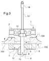
figure 3 est une vue en coupe de l'outillage en place sur le caisson d'atterrisseur.
- the
figure 1 is a perspective view of the location tooling of the invention; - the
figure 2 is a view of the tooling of thefigure 1 in place on the upper part of an aircraft landing gear box; - the
figure 3 is a sectional view of the tool in place on the landing gear box.
En référence aux figures, l'outillage de localisation de l'invention est destiné à équiper ici un caisson 100 d'atterrisseur qui comporte un corps 101 s'étendant ici selon un axe Z et terminé en partie supérieure par une traverse 102 s'étendant selon un axe X, dont les extrémités sont destinées à recevoir des pivots d'articulation de l'atterrisseur sur l'aéronef. La traverse 102 est percée sensiblement selon l'axe Z et présente ainsi un alésage qui traverse la paroi de la traverse 102 entre une face interne 103 et une face externe 104 de celle-ci. Sur la
L'outillage de localisation comporte un organe de localisation, ici un centreur 1, qui est destiné à dépasser de la pièce à équiper pour faciliter son positionnement dans un gabarit d'usinage ou de montage. Le centreur 1 comporte ici une jupe cylindrique 2 qui est percée à intervalles réguliers, et qui est prolongée axialement par une portée 3 ayant un diamètre extérieur ajusté à celui de l'alésage du caisson 100 pour y pénétrer avec un faible jeu. Comme cela est visible à la
La portée 3 a été fraisée en son centre pour présenter un logement central à flancs parallèles 5. Une bride 6 de forme oblongue présentant deux flancs parallèles est positionnée dans le logement de la portée de sorte que les flancs de la bride 6 et les flancs du logement 5 coopèrent avec un faible jeu. Un passage traversant 7 est ménagé dans la bride 6 pour permettre l'introduction dans celle-ci d'une tige de serrage 8 filetée. Le passage traversant 7 est lui-même de contour oblong parallèle à un contour extérieur de la bride 6. La tige de serrage 8 a une extrémité munie d'une tête 9 à base sphérique. Ici, la tête 9 est rapportée sur l'extrémité de la tige de serrage et maintenue sur celle-ci au moyen d'une broche 10.The
Une empreinte sphérique est ménagée au milieu de du passage traversant 7, dans les flancs intérieurs de celui-ci, pour recevoir à rotulage la base sphérique de la tête 9, ce qui permet une libre orientation de la bride 6. Sur la
Par ailleurs, la tige de serrage 8 passe au travers d'un perçage central du centreur 1 pour dépasser d'un fond de celui-ci et recevoir un écrou de serrage 12. La tige de serrage 8 est prolongée d'une tige de manoeuvre 13 terminée par une poignée de manoeuvre 14.Furthermore, the
L'utilisation de l'outil de localisation de l'invention est la suivante. On commence par faire pénétrer la bride 6 à l'intérieur de l'alésage de la pièce 100. Pour ce faire, l'écrou 12 est enlevé, et la tige de serrage 8 repoussée à fond dans le perçage central du centreur 1. Grâce à la forme oblongue du passage traversant 7, la bride peut être inclinée et couchée contre la tige de serrage 8, ce qui facilite l'introduction de la bride 6 dans la pièce 100.The use of the location tool of the invention is as follows. The
On rapporte ensuite le centreur 1 dans l'alésage de la pièce 100, jusqu'à ce que la face arrière 4 du cylindre de prise 2 du centreur 1 vienne en butée contre la face externe 104. En tirant sur la tige de serrage 8 via la poignée de manoeuvre 14, on force la bride 6 à buter contre la face interne 103 et ainsi à se redresser. La base sphérique de la tête 9 est alors introduite dans l'empreinte sphérique de la bride 6. Par tâtonnement, on oriente la bride de sorte à la faire pénétrer dans le logement 5 de la portée 3. La bride 6 est alors astreinte angulairement. De préférence, avant serrage, on orientera le centreur 1 de sorte que la bride 6 s'étende contre la face interne 103 selon une ligne de plus grande pente par rapport à la face externe 104. Enfin, on visse l'écrou 12 sur la tige de serrage 8 jusqu'à son serrage contre le fond du centreur 1. L'outillage est alors en place. La possibilité de rotulage offerte par la coopération de l'empreinte sphérique de la bride 6 avec la base sphérique de la tête 9 permet la libre orientation de la bride de sorte que celle-ci appuie de façon égale sur la face interne de part et d'autre de la tige de serrage 8, en s'accommodant de l'inclinaison de la face interne 103.The
En outre, le positionnement de la bride 6 dans le logement 5 empêche les flancs de la bride de s'écarter sous l'effet du serrage.In addition, the positioning of the
L'invention n'est bien sûr pas limitée à ce qui vient d'être décrit, mais englobe toute variante entrant dans le cadre défini par les revendications.The invention is of course not limited to what has just been described, but encompasses any variant entering within the scope defined by the claims.
En particulier, bien que l'on ait indiqué que la base de la tête de la tige de serrage était sphérique et coopérait avec une empreinte sphérique ménagée dans des flancs intérieurs d'un passage traversant la bride, on pourra plus généralement prévoir une tête à base convexe coopérant avec une surface d'appui de la bride qui permet sa libre orientation pour appuyer de façon homogène sur la face interne de la pièce. Par exemple, on pourra prévoir une tête à base cylindrique convexe coopérant avec une surface d'appui concave également cylindrique.In particular, although it has been indicated that the base of the head of the clamping rod is spherical and cooperates with a spherical imprint formed in the inner flanks of a passage passing through the flange, it will more generally be possible to provide a head to convex base cooperating with a bearing surface of the flange which allows its free orientation to support homogeneously on the inner face of the part. For example, it is possible to provide a convex cylindrical base head cooperating with a concave bearing surface that is also cylindrical.
Claims (6)
- A locating tool intended to be installed in a bore in a component that passes through a wall of the latter delimited between an outer face and an inner face, having:- a locating member (2) that is extended by a seating (3) that projects from the latter for the introduction thereof with a tight fit into the bore in the component until a shoulder (4) that ends the seating makes contact with the outer face of the component;- a flange (6) that is intended to bear against the inner face of the component characterized by a clamping rod (8) that is equipped with a head (9) that bears against the flange, said clamping rod (8) passing through the flange and the centering member in order to take a clamping nut (12) for clamping against a bottom of the locating member;and in that the head of the rod has a base with a convex shape that engages with a bearing surface on the flange so as to allow an angular orientation of the flange.
- The locating tool as claimed in claim 1, wherein the base of the head of the clamping screw (8) has a spherical shape and engages with a spherical impression made in the internal side walls of a through-passage in the flange.
- The locating tool as claimed in claim 1, wherein the flange has an elongate shape and has parallel side walls, being received in a central housing (5) in the seating that has parallel side walls.
- The locating tool as claimed in claim 3, wherein the flange has an elongate through-passage.
- The locating tool as claimed in claim 1, wherein the locating member is a cylindrical skirt (2).
- The locating tool as claimed in claim 1, wherein the clamping rod (8) is extended by a maneuvering rod (13) ended by a maneuvering handle (14).
Applications Claiming Priority (2)
| Application Number | Priority Date | Filing Date | Title |
|---|---|---|---|
| CA2767791A CA2767791C (en) | 2012-02-13 | 2012-02-13 | Positoning tool, specificallly for the extremity of a sliding rod or a landing gear housing on an aircraft |
| PCT/CA2013/050070 WO2013120193A1 (en) | 2012-02-13 | 2013-01-30 | Locating tool, in particular for a sliding rod end or an aircraft landing gear casing |
Publications (3)
| Publication Number | Publication Date |
|---|---|
| EP2814635A1 EP2814635A1 (en) | 2014-12-24 |
| EP2814635A4 EP2814635A4 (en) | 2015-10-14 |
| EP2814635B1 true EP2814635B1 (en) | 2016-07-13 |
Family
ID=48980497
Family Applications (1)
| Application Number | Title | Priority Date | Filing Date |
|---|---|---|---|
| EP13749669.1A Active EP2814635B1 (en) | 2012-02-13 | 2013-01-30 | Locating tool, in particular for a sliding rod end or an aircraft landing gear casing |
Country Status (4)
| Country | Link |
|---|---|
| EP (1) | EP2814635B1 (en) |
| CA (1) | CA2767791C (en) |
| MX (1) | MX355449B (en) |
| WO (1) | WO2013120193A1 (en) |
Family Cites Families (2)
| Publication number | Priority date | Publication date | Assignee | Title |
|---|---|---|---|---|
| US6855099B2 (en) * | 2001-10-31 | 2005-02-15 | The Boeing Company | Manufacturing system for aircraft structures and other large structures |
| CN201833217U (en) * | 2010-07-30 | 2011-05-18 | 中国航空工业集团公司北京航空制造工程研究所 | Three-dimensional positioning apparatus |
-
2012
- 2012-02-13 CA CA2767791A patent/CA2767791C/en active Active
-
2013
- 2013-01-30 WO PCT/CA2013/050070 patent/WO2013120193A1/en active Application Filing
- 2013-01-30 MX MX2014009560A patent/MX355449B/en active IP Right Grant
- 2013-01-30 EP EP13749669.1A patent/EP2814635B1/en active Active
Also Published As
| Publication number | Publication date |
|---|---|
| MX355449B (en) | 2018-04-18 |
| EP2814635A1 (en) | 2014-12-24 |
| EP2814635A4 (en) | 2015-10-14 |
| MX2014009560A (en) | 2015-01-26 |
| WO2013120193A1 (en) | 2013-08-22 |
| CA2767791A1 (en) | 2013-08-13 |
| CA2767791C (en) | 2014-07-08 |
Similar Documents
| Publication | Publication Date | Title |
|---|---|---|
| FR2599703A1 (en) | HEADSET FOR PARTICULARLY LOCKING BICYCLES WITH RESPECT TO THE FORK | |
| EP3684549B1 (en) | Fastening socket for assembling structures and associated attachment | |
| FR3046137A1 (en) | METHOD FOR ALIGNING A FIRST ORIFICE OF A FIRST PART WITH A SECOND ORIFICE OF A SECOND PART AND KIT FOR IMPLEMENTING IT | |
| WO2000005035A1 (en) | Device for centring and clamping a sheet metal assembly or a mechanical part | |
| EP3589445A1 (en) | Quick-clamping spindle | |
| EP1553310B1 (en) | A reversible device for locking an end piece on a structure with adjustable position | |
| FR3047759A1 (en) | DOOR STAND FOR QUICK ASSEMBLY AND DISASSEMBLY | |
| FR3008156A1 (en) | TENSIONER DEVICE OF A TRACTION MEMBER, MOTOR EQUIPPED WITH SUCH TENDERING DEVICE AND METHOD OF IMPLEMENTING THE SAME | |
| EP2814635B1 (en) | Locating tool, in particular for a sliding rod end or an aircraft landing gear casing | |
| EP3130419B1 (en) | Adapter for a boring grate and boring grate provided with said adapter | |
| FR3036361A1 (en) | IMPROVED FIXING ELEMENT | |
| EP1882794A1 (en) | Device for assembling vertical edges of form panels | |
| FR2919693A1 (en) | DEVICE FOR ASSEMBLING A STRUCTURAL ELEMENT AND A SUPERPOSED PLATE | |
| FR3041893A1 (en) | TOOL FOR EXTRACTING A FLATPLATE PLATE TO AN OUTER WALL OF AN AIRCRAFT | |
| EP3299650A1 (en) | A method for equiping the end of a thin walled tube with an axial stop that is adjustable by a threaded joint | |
| EP1775815B1 (en) | Flush-mounted box with optimal fixation | |
| EP2392750A1 (en) | Tie for removably supporting and attaching a structure to a wall, provided with an adapter | |
| EP3019430B1 (en) | Lifting ring | |
| FR2974749A1 (en) | Tool for installation of O-ring around threaded rod in car, has portion forming pusher that is adapted to push O-ring along threaded rod, and gripping part made of cylindrical handle | |
| LU102432B1 (en) | Swivel lifting point for lifting loads | |
| FR3070136B1 (en) | TOOLING ASSEMBLY OF TWO CONDUITS | |
| EP2094986B1 (en) | Linking device between pinion shaft and steering column cap | |
| FR2887308A1 (en) | Panel assembling system, has rod with ball-shaped end engaged in recess of connecting part`s head, and pin/clamp locking rod in housing arranged in one of set of panels, where panels are maintained in position by connecting points | |
| WO2022069378A1 (en) | Electrical equipotential connection device | |
| FR2972131A1 (en) | Hand tool i.e. multigrip pliers, has treated steel ball placed within housing to produce radial deformation of axle against inner wall of bore of connecting unit such that axle and part of tool are connected with each other |
Legal Events
| Date | Code | Title | Description |
|---|---|---|---|
| PUAI | Public reference made under article 153(3) epc to a published international application that has entered the european phase |
Free format text: ORIGINAL CODE: 0009012 |
|
| 17P | Request for examination filed |
Effective date: 20140731 |
|
| AK | Designated contracting states |
Kind code of ref document: A1 Designated state(s): AL AT BE BG CH CY CZ DE DK EE ES FI FR GB GR HR HU IE IS IT LI LT LU LV MC MK MT NL NO PL PT RO RS SE SI SK SM TR |
|
| AX | Request for extension of the european patent |
Extension state: BA ME |
|
| DAX | Request for extension of the european patent (deleted) | ||
| RA4 | Supplementary search report drawn up and despatched (corrected) |
Effective date: 20150914 |
|
| RIC1 | Information provided on ipc code assigned before grant |
Ipc: B64F 5/00 20060101AFI20150908BHEP |
|
| REG | Reference to a national code |
Ref country code: DE Ref legal event code: R079 Ref document number: 602013009420 Country of ref document: DE Free format text: PREVIOUS MAIN CLASS: B23Q0003180000 Ipc: B64F0005000000 |
|
| GRAP | Despatch of communication of intention to grant a patent |
Free format text: ORIGINAL CODE: EPIDOSNIGR1 |
|
| RIC1 | Information provided on ipc code assigned before grant |
Ipc: B64F 5/00 20060101AFI20160218BHEP |
|
| INTG | Intention to grant announced |
Effective date: 20160321 |
|
| GRAS | Grant fee paid |
Free format text: ORIGINAL CODE: EPIDOSNIGR3 |
|
| GRAA | (expected) grant |
Free format text: ORIGINAL CODE: 0009210 |
|
| AK | Designated contracting states |
Kind code of ref document: B1 Designated state(s): AL AT BE BG CH CY CZ DE DK EE ES FI FR GB GR HR HU IE IS IT LI LT LU LV MC MK MT NL NO PL PT RO RS SE SI SK SM TR |
|
| REG | Reference to a national code |
Ref country code: GB Ref legal event code: FG4D Free format text: NOT ENGLISH |
|
| REG | Reference to a national code |
Ref country code: AT Ref legal event code: REF Ref document number: 812064 Country of ref document: AT Kind code of ref document: T Effective date: 20160715 Ref country code: CH Ref legal event code: EP |
|
| REG | Reference to a national code |
Ref country code: IE Ref legal event code: FG4D Free format text: LANGUAGE OF EP DOCUMENT: FRENCH |
|
| REG | Reference to a national code |
Ref country code: DE Ref legal event code: R096 Ref document number: 602013009420 Country of ref document: DE |
|
| REG | Reference to a national code |
Ref country code: LT Ref legal event code: MG4D |
|
| REG | Reference to a national code |
Ref country code: NL Ref legal event code: MP Effective date: 20160713 |
|
| REG | Reference to a national code |
Ref country code: AT Ref legal event code: MK05 Ref document number: 812064 Country of ref document: AT Kind code of ref document: T Effective date: 20160713 |
|
| REG | Reference to a national code |
Ref country code: FR Ref legal event code: PLFP Year of fee payment: 5 |
|
| PG25 | Lapsed in a contracting state [announced via postgrant information from national office to epo] |
Ref country code: FI Free format text: LAPSE BECAUSE OF FAILURE TO SUBMIT A TRANSLATION OF THE DESCRIPTION OR TO PAY THE FEE WITHIN THE PRESCRIBED TIME-LIMIT Effective date: 20160713 Ref country code: HR Free format text: LAPSE BECAUSE OF FAILURE TO SUBMIT A TRANSLATION OF THE DESCRIPTION OR TO PAY THE FEE WITHIN THE PRESCRIBED TIME-LIMIT Effective date: 20160713 Ref country code: NO Free format text: LAPSE BECAUSE OF FAILURE TO SUBMIT A TRANSLATION OF THE DESCRIPTION OR TO PAY THE FEE WITHIN THE PRESCRIBED TIME-LIMIT Effective date: 20161013 Ref country code: RS Free format text: LAPSE BECAUSE OF FAILURE TO SUBMIT A TRANSLATION OF THE DESCRIPTION OR TO PAY THE FEE WITHIN THE PRESCRIBED TIME-LIMIT Effective date: 20160713 Ref country code: NL Free format text: LAPSE BECAUSE OF FAILURE TO SUBMIT A TRANSLATION OF THE DESCRIPTION OR TO PAY THE FEE WITHIN THE PRESCRIBED TIME-LIMIT Effective date: 20160713 Ref country code: LT Free format text: LAPSE BECAUSE OF FAILURE TO SUBMIT A TRANSLATION OF THE DESCRIPTION OR TO PAY THE FEE WITHIN THE PRESCRIBED TIME-LIMIT Effective date: 20160713 Ref country code: IS Free format text: LAPSE BECAUSE OF FAILURE TO SUBMIT A TRANSLATION OF THE DESCRIPTION OR TO PAY THE FEE WITHIN THE PRESCRIBED TIME-LIMIT Effective date: 20161113 Ref country code: IT Free format text: LAPSE BECAUSE OF FAILURE TO SUBMIT A TRANSLATION OF THE DESCRIPTION OR TO PAY THE FEE WITHIN THE PRESCRIBED TIME-LIMIT Effective date: 20160713 |
|
| PG25 | Lapsed in a contracting state [announced via postgrant information from national office to epo] |
Ref country code: ES Free format text: LAPSE BECAUSE OF FAILURE TO SUBMIT A TRANSLATION OF THE DESCRIPTION OR TO PAY THE FEE WITHIN THE PRESCRIBED TIME-LIMIT Effective date: 20160713 Ref country code: PT Free format text: LAPSE BECAUSE OF FAILURE TO SUBMIT A TRANSLATION OF THE DESCRIPTION OR TO PAY THE FEE WITHIN THE PRESCRIBED TIME-LIMIT Effective date: 20161114 Ref country code: PL Free format text: LAPSE BECAUSE OF FAILURE TO SUBMIT A TRANSLATION OF THE DESCRIPTION OR TO PAY THE FEE WITHIN THE PRESCRIBED TIME-LIMIT Effective date: 20160713 Ref country code: GR Free format text: LAPSE BECAUSE OF FAILURE TO SUBMIT A TRANSLATION OF THE DESCRIPTION OR TO PAY THE FEE WITHIN THE PRESCRIBED TIME-LIMIT Effective date: 20161014 Ref country code: AT Free format text: LAPSE BECAUSE OF FAILURE TO SUBMIT A TRANSLATION OF THE DESCRIPTION OR TO PAY THE FEE WITHIN THE PRESCRIBED TIME-LIMIT Effective date: 20160713 Ref country code: LV Free format text: LAPSE BECAUSE OF FAILURE TO SUBMIT A TRANSLATION OF THE DESCRIPTION OR TO PAY THE FEE WITHIN THE PRESCRIBED TIME-LIMIT Effective date: 20160713 Ref country code: SE Free format text: LAPSE BECAUSE OF FAILURE TO SUBMIT A TRANSLATION OF THE DESCRIPTION OR TO PAY THE FEE WITHIN THE PRESCRIBED TIME-LIMIT Effective date: 20160713 |
|
| REG | Reference to a national code |
Ref country code: DE Ref legal event code: R097 Ref document number: 602013009420 Country of ref document: DE |
|
| PG25 | Lapsed in a contracting state [announced via postgrant information from national office to epo] |
Ref country code: EE Free format text: LAPSE BECAUSE OF FAILURE TO SUBMIT A TRANSLATION OF THE DESCRIPTION OR TO PAY THE FEE WITHIN THE PRESCRIBED TIME-LIMIT Effective date: 20160713 Ref country code: RO Free format text: LAPSE BECAUSE OF FAILURE TO SUBMIT A TRANSLATION OF THE DESCRIPTION OR TO PAY THE FEE WITHIN THE PRESCRIBED TIME-LIMIT Effective date: 20160713 |
|
| PLBE | No opposition filed within time limit |
Free format text: ORIGINAL CODE: 0009261 |
|
| STAA | Information on the status of an ep patent application or granted ep patent |
Free format text: STATUS: NO OPPOSITION FILED WITHIN TIME LIMIT |
|
| PG25 | Lapsed in a contracting state [announced via postgrant information from national office to epo] |
Ref country code: SK Free format text: LAPSE BECAUSE OF FAILURE TO SUBMIT A TRANSLATION OF THE DESCRIPTION OR TO PAY THE FEE WITHIN THE PRESCRIBED TIME-LIMIT Effective date: 20160713 Ref country code: DK Free format text: LAPSE BECAUSE OF FAILURE TO SUBMIT A TRANSLATION OF THE DESCRIPTION OR TO PAY THE FEE WITHIN THE PRESCRIBED TIME-LIMIT Effective date: 20160713 Ref country code: SM Free format text: LAPSE BECAUSE OF FAILURE TO SUBMIT A TRANSLATION OF THE DESCRIPTION OR TO PAY THE FEE WITHIN THE PRESCRIBED TIME-LIMIT Effective date: 20160713 Ref country code: BE Free format text: LAPSE BECAUSE OF NON-PAYMENT OF DUE FEES Effective date: 20170131 Ref country code: CZ Free format text: LAPSE BECAUSE OF FAILURE TO SUBMIT A TRANSLATION OF THE DESCRIPTION OR TO PAY THE FEE WITHIN THE PRESCRIBED TIME-LIMIT Effective date: 20160713 Ref country code: BG Free format text: LAPSE BECAUSE OF FAILURE TO SUBMIT A TRANSLATION OF THE DESCRIPTION OR TO PAY THE FEE WITHIN THE PRESCRIBED TIME-LIMIT Effective date: 20161013 |
|
| 26N | No opposition filed |
Effective date: 20170418 |
|
| PG25 | Lapsed in a contracting state [announced via postgrant information from national office to epo] |
Ref country code: SI Free format text: LAPSE BECAUSE OF FAILURE TO SUBMIT A TRANSLATION OF THE DESCRIPTION OR TO PAY THE FEE WITHIN THE PRESCRIBED TIME-LIMIT Effective date: 20160713 |
|
| REG | Reference to a national code |
Ref country code: CH Ref legal event code: PL |
|
| PG25 | Lapsed in a contracting state [announced via postgrant information from national office to epo] |
Ref country code: MC Free format text: LAPSE BECAUSE OF FAILURE TO SUBMIT A TRANSLATION OF THE DESCRIPTION OR TO PAY THE FEE WITHIN THE PRESCRIBED TIME-LIMIT Effective date: 20160713 |
|
| PG25 | Lapsed in a contracting state [announced via postgrant information from national office to epo] |
Ref country code: LI Free format text: LAPSE BECAUSE OF NON-PAYMENT OF DUE FEES Effective date: 20170131 Ref country code: CH Free format text: LAPSE BECAUSE OF NON-PAYMENT OF DUE FEES Effective date: 20170131 |
|
| REG | Reference to a national code |
Ref country code: IE Ref legal event code: MM4A |
|
| PG25 | Lapsed in a contracting state [announced via postgrant information from national office to epo] |
Ref country code: LU Free format text: LAPSE BECAUSE OF NON-PAYMENT OF DUE FEES Effective date: 20170130 |
|
| REG | Reference to a national code |
Ref country code: FR Ref legal event code: PLFP Year of fee payment: 6 |
|
| REG | Reference to a national code |
Ref country code: BE Ref legal event code: MM Effective date: 20170131 |
|
| PG25 | Lapsed in a contracting state [announced via postgrant information from national office to epo] |
Ref country code: IE Free format text: LAPSE BECAUSE OF NON-PAYMENT OF DUE FEES Effective date: 20170130 |
|
| PG25 | Lapsed in a contracting state [announced via postgrant information from national office to epo] |
Ref country code: MT Free format text: LAPSE BECAUSE OF FAILURE TO SUBMIT A TRANSLATION OF THE DESCRIPTION OR TO PAY THE FEE WITHIN THE PRESCRIBED TIME-LIMIT Effective date: 20160713 |
|
| PG25 | Lapsed in a contracting state [announced via postgrant information from national office to epo] |
Ref country code: AL Free format text: LAPSE BECAUSE OF FAILURE TO SUBMIT A TRANSLATION OF THE DESCRIPTION OR TO PAY THE FEE WITHIN THE PRESCRIBED TIME-LIMIT Effective date: 20160713 |
|
| PG25 | Lapsed in a contracting state [announced via postgrant information from national office to epo] |
Ref country code: HU Free format text: LAPSE BECAUSE OF FAILURE TO SUBMIT A TRANSLATION OF THE DESCRIPTION OR TO PAY THE FEE WITHIN THE PRESCRIBED TIME-LIMIT; INVALID AB INITIO Effective date: 20130130 |
|
| PG25 | Lapsed in a contracting state [announced via postgrant information from national office to epo] |
Ref country code: CY Free format text: LAPSE BECAUSE OF FAILURE TO SUBMIT A TRANSLATION OF THE DESCRIPTION OR TO PAY THE FEE WITHIN THE PRESCRIBED TIME-LIMIT Effective date: 20160713 |
|
| PG25 | Lapsed in a contracting state [announced via postgrant information from national office to epo] |
Ref country code: MK Free format text: LAPSE BECAUSE OF FAILURE TO SUBMIT A TRANSLATION OF THE DESCRIPTION OR TO PAY THE FEE WITHIN THE PRESCRIBED TIME-LIMIT Effective date: 20160713 |
|
| PG25 | Lapsed in a contracting state [announced via postgrant information from national office to epo] |
Ref country code: TR Free format text: LAPSE BECAUSE OF FAILURE TO SUBMIT A TRANSLATION OF THE DESCRIPTION OR TO PAY THE FEE WITHIN THE PRESCRIBED TIME-LIMIT Effective date: 20160713 |
|
| PGFP | Annual fee paid to national office [announced via postgrant information from national office to epo] |
Ref country code: DE Payment date: 20211215 Year of fee payment: 10 |
|
| REG | Reference to a national code |
Ref country code: DE Ref legal event code: R119 Ref document number: 602013009420 Country of ref document: DE |
|
| PG25 | Lapsed in a contracting state [announced via postgrant information from national office to epo] |
Ref country code: DE Free format text: LAPSE BECAUSE OF NON-PAYMENT OF DUE FEES Effective date: 20230801 |
|
| PGFP | Annual fee paid to national office [announced via postgrant information from national office to epo] |
Ref country code: GB Payment date: 20231219 Year of fee payment: 12 |
|
| PGFP | Annual fee paid to national office [announced via postgrant information from national office to epo] |
Ref country code: FR Payment date: 20231219 Year of fee payment: 12 |