EP2814546B1 - Stiftartiger injektor und elektronische aufsteckvorrichtung dafür - Google Patents
Stiftartiger injektor und elektronische aufsteckvorrichtung dafür Download PDFInfo
- Publication number
- EP2814546B1 EP2814546B1 EP13709047.8A EP13709047A EP2814546B1 EP 2814546 B1 EP2814546 B1 EP 2814546B1 EP 13709047 A EP13709047 A EP 13709047A EP 2814546 B1 EP2814546 B1 EP 2814546B1
- Authority
- EP
- European Patent Office
- Prior art keywords
- injection device
- supplemental
- injection
- supplemental device
- protuberances
- Prior art date
- Legal status (The legal status is an assumption and is not a legal conclusion. Google has not performed a legal analysis and makes no representation as to the accuracy of the status listed.)
- Active
Links
Images


Classifications
-
- G—PHYSICS
- G16—INFORMATION AND COMMUNICATION TECHNOLOGY [ICT] SPECIALLY ADAPTED FOR SPECIFIC APPLICATION FIELDS
- G16H—HEALTHCARE INFORMATICS, i.e. INFORMATION AND COMMUNICATION TECHNOLOGY [ICT] SPECIALLY ADAPTED FOR THE HANDLING OR PROCESSING OF MEDICAL OR HEALTHCARE DATA
- G16H20/00—ICT specially adapted for therapies or health-improving plans, e.g. for handling prescriptions, for steering therapy or for monitoring patient compliance
- G16H20/10—ICT specially adapted for therapies or health-improving plans, e.g. for handling prescriptions, for steering therapy or for monitoring patient compliance relating to drugs or medications, e.g. for ensuring correct administration to patients
- G16H20/17—ICT specially adapted for therapies or health-improving plans, e.g. for handling prescriptions, for steering therapy or for monitoring patient compliance relating to drugs or medications, e.g. for ensuring correct administration to patients delivered via infusion or injection
-
- A—HUMAN NECESSITIES
- A61—MEDICAL OR VETERINARY SCIENCE; HYGIENE
- A61B—DIAGNOSIS; SURGERY; IDENTIFICATION
- A61B5/00—Measuring for diagnostic purposes; Identification of persons
- A61B5/145—Measuring characteristics of blood in vivo, e.g. gas concentration or pH-value ; Measuring characteristics of body fluids or tissues, e.g. interstitial fluid or cerebral tissue
- A61B5/14532—Measuring characteristics of blood in vivo, e.g. gas concentration or pH-value ; Measuring characteristics of body fluids or tissues, e.g. interstitial fluid or cerebral tissue for measuring glucose, e.g. by tissue impedance measurement
-
- A—HUMAN NECESSITIES
- A61—MEDICAL OR VETERINARY SCIENCE; HYGIENE
- A61M—DEVICES FOR INTRODUCING MEDIA INTO, OR ONTO, THE BODY; DEVICES FOR TRANSDUCING BODY MEDIA OR FOR TAKING MEDIA FROM THE BODY; DEVICES FOR PRODUCING OR ENDING SLEEP OR STUPOR
- A61M5/00—Devices for bringing media into the body in a subcutaneous, intra-vascular or intramuscular way; Accessories therefor, e.g. filling or cleaning devices, arm-rests
- A61M5/178—Syringes
- A61M5/24—Ampoule syringes, i.e. syringes with needle for use in combination with replaceable ampoules or carpules, e.g. automatic
-
- A—HUMAN NECESSITIES
- A61—MEDICAL OR VETERINARY SCIENCE; HYGIENE
- A61M—DEVICES FOR INTRODUCING MEDIA INTO, OR ONTO, THE BODY; DEVICES FOR TRANSDUCING BODY MEDIA OR FOR TAKING MEDIA FROM THE BODY; DEVICES FOR PRODUCING OR ENDING SLEEP OR STUPOR
- A61M5/00—Devices for bringing media into the body in a subcutaneous, intra-vascular or intramuscular way; Accessories therefor, e.g. filling or cleaning devices, arm-rests
- A61M5/178—Syringes
- A61M5/31—Details
- A61M5/3146—Priming, e.g. purging, reducing backlash or clearance
-
- A—HUMAN NECESSITIES
- A61—MEDICAL OR VETERINARY SCIENCE; HYGIENE
- A61M—DEVICES FOR INTRODUCING MEDIA INTO, OR ONTO, THE BODY; DEVICES FOR TRANSDUCING BODY MEDIA OR FOR TAKING MEDIA FROM THE BODY; DEVICES FOR PRODUCING OR ENDING SLEEP OR STUPOR
- A61M5/00—Devices for bringing media into the body in a subcutaneous, intra-vascular or intramuscular way; Accessories therefor, e.g. filling or cleaning devices, arm-rests
- A61M5/178—Syringes
- A61M5/31—Details
- A61M5/315—Pistons; Piston-rods; Guiding, blocking or restricting the movement of the rod or piston; Appliances on the rod for facilitating dosing ; Dosing mechanisms
- A61M5/31525—Dosing
-
- A—HUMAN NECESSITIES
- A61—MEDICAL OR VETERINARY SCIENCE; HYGIENE
- A61M—DEVICES FOR INTRODUCING MEDIA INTO, OR ONTO, THE BODY; DEVICES FOR TRANSDUCING BODY MEDIA OR FOR TAKING MEDIA FROM THE BODY; DEVICES FOR PRODUCING OR ENDING SLEEP OR STUPOR
- A61M5/00—Devices for bringing media into the body in a subcutaneous, intra-vascular or intramuscular way; Accessories therefor, e.g. filling or cleaning devices, arm-rests
- A61M5/178—Syringes
- A61M5/31—Details
- A61M5/32—Needles; Details of needles pertaining to their connection with syringe or hub; Accessories for bringing the needle into, or holding the needle on, the body; Devices for protection of needles
- A61M5/3202—Devices for protection of the needle before use, e.g. caps
-
- F—MECHANICAL ENGINEERING; LIGHTING; HEATING; WEAPONS; BLASTING
- F16—ENGINEERING ELEMENTS AND UNITS; GENERAL MEASURES FOR PRODUCING AND MAINTAINING EFFECTIVE FUNCTIONING OF MACHINES OR INSTALLATIONS; THERMAL INSULATION IN GENERAL
- F16B—DEVICES FOR FASTENING OR SECURING CONSTRUCTIONAL ELEMENTS OR MACHINE PARTS TOGETHER, e.g. NAILS, BOLTS, CIRCLIPS, CLAMPS, CLIPS OR WEDGES; JOINTS OR JOINTING
- F16B1/00—Devices for securing together, or preventing relative movement between, constructional elements or machine parts
-
- F—MECHANICAL ENGINEERING; LIGHTING; HEATING; WEAPONS; BLASTING
- F16—ENGINEERING ELEMENTS AND UNITS; GENERAL MEASURES FOR PRODUCING AND MAINTAINING EFFECTIVE FUNCTIONING OF MACHINES OR INSTALLATIONS; THERMAL INSULATION IN GENERAL
- F16B—DEVICES FOR FASTENING OR SECURING CONSTRUCTIONAL ELEMENTS OR MACHINE PARTS TOGETHER, e.g. NAILS, BOLTS, CIRCLIPS, CLAMPS, CLIPS OR WEDGES; JOINTS OR JOINTING
- F16B2/00—Friction-grip releasable fastenings
- F16B2/02—Clamps, i.e. with gripping action effected by positive means other than the inherent resistance to deformation of the material of the fastening
-
- F—MECHANICAL ENGINEERING; LIGHTING; HEATING; WEAPONS; BLASTING
- F16—ENGINEERING ELEMENTS AND UNITS; GENERAL MEASURES FOR PRODUCING AND MAINTAINING EFFECTIVE FUNCTIONING OF MACHINES OR INSTALLATIONS; THERMAL INSULATION IN GENERAL
- F16B—DEVICES FOR FASTENING OR SECURING CONSTRUCTIONAL ELEMENTS OR MACHINE PARTS TOGETHER, e.g. NAILS, BOLTS, CIRCLIPS, CLAMPS, CLIPS OR WEDGES; JOINTS OR JOINTING
- F16B2/00—Friction-grip releasable fastenings
- F16B2/20—Clips, i.e. with gripping action effected solely by the inherent resistance to deformation of the material of the fastening
-
- F—MECHANICAL ENGINEERING; LIGHTING; HEATING; WEAPONS; BLASTING
- F16—ENGINEERING ELEMENTS AND UNITS; GENERAL MEASURES FOR PRODUCING AND MAINTAINING EFFECTIVE FUNCTIONING OF MACHINES OR INSTALLATIONS; THERMAL INSULATION IN GENERAL
- F16B—DEVICES FOR FASTENING OR SECURING CONSTRUCTIONAL ELEMENTS OR MACHINE PARTS TOGETHER, e.g. NAILS, BOLTS, CIRCLIPS, CLAMPS, CLIPS OR WEDGES; JOINTS OR JOINTING
- F16B21/00—Means for preventing relative axial movement of a pin, spigot, shaft or the like and a member surrounding it; Stud-and-socket releasable fastenings
- F16B21/02—Releasable fastening devices locking by rotation
-
- F—MECHANICAL ENGINEERING; LIGHTING; HEATING; WEAPONS; BLASTING
- F16—ENGINEERING ELEMENTS AND UNITS; GENERAL MEASURES FOR PRODUCING AND MAINTAINING EFFECTIVE FUNCTIONING OF MACHINES OR INSTALLATIONS; THERMAL INSULATION IN GENERAL
- F16B—DEVICES FOR FASTENING OR SECURING CONSTRUCTIONAL ELEMENTS OR MACHINE PARTS TOGETHER, e.g. NAILS, BOLTS, CIRCLIPS, CLAMPS, CLIPS OR WEDGES; JOINTS OR JOINTING
- F16B21/00—Means for preventing relative axial movement of a pin, spigot, shaft or the like and a member surrounding it; Stud-and-socket releasable fastenings
- F16B21/06—Releasable fastening devices with snap-action
-
- F—MECHANICAL ENGINEERING; LIGHTING; HEATING; WEAPONS; BLASTING
- F16—ENGINEERING ELEMENTS AND UNITS; GENERAL MEASURES FOR PRODUCING AND MAINTAINING EFFECTIVE FUNCTIONING OF MACHINES OR INSTALLATIONS; THERMAL INSULATION IN GENERAL
- F16B—DEVICES FOR FASTENING OR SECURING CONSTRUCTIONAL ELEMENTS OR MACHINE PARTS TOGETHER, e.g. NAILS, BOLTS, CIRCLIPS, CLAMPS, CLIPS OR WEDGES; JOINTS OR JOINTING
- F16B7/00—Connections of rods or tubes, e.g. of non-circular section, mutually, including resilient connections
- F16B7/04—Clamping or clipping connections
-
- G—PHYSICS
- G16—INFORMATION AND COMMUNICATION TECHNOLOGY [ICT] SPECIALLY ADAPTED FOR SPECIFIC APPLICATION FIELDS
- G16H—HEALTHCARE INFORMATICS, i.e. INFORMATION AND COMMUNICATION TECHNOLOGY [ICT] SPECIALLY ADAPTED FOR THE HANDLING OR PROCESSING OF MEDICAL OR HEALTHCARE DATA
- G16H20/00—ICT specially adapted for therapies or health-improving plans, e.g. for handling prescriptions, for steering therapy or for monitoring patient compliance
- G16H20/10—ICT specially adapted for therapies or health-improving plans, e.g. for handling prescriptions, for steering therapy or for monitoring patient compliance relating to drugs or medications, e.g. for ensuring correct administration to patients
-
- G—PHYSICS
- G16—INFORMATION AND COMMUNICATION TECHNOLOGY [ICT] SPECIALLY ADAPTED FOR SPECIFIC APPLICATION FIELDS
- G16H—HEALTHCARE INFORMATICS, i.e. INFORMATION AND COMMUNICATION TECHNOLOGY [ICT] SPECIALLY ADAPTED FOR THE HANDLING OR PROCESSING OF MEDICAL OR HEALTHCARE DATA
- G16H40/00—ICT specially adapted for the management or administration of healthcare resources or facilities; ICT specially adapted for the management or operation of medical equipment or devices
- G16H40/60—ICT specially adapted for the management or administration of healthcare resources or facilities; ICT specially adapted for the management or operation of medical equipment or devices for the operation of medical equipment or devices
- G16H40/63—ICT specially adapted for the management or administration of healthcare resources or facilities; ICT specially adapted for the management or operation of medical equipment or devices for the operation of medical equipment or devices for local operation
-
- G—PHYSICS
- G16—INFORMATION AND COMMUNICATION TECHNOLOGY [ICT] SPECIALLY ADAPTED FOR SPECIFIC APPLICATION FIELDS
- G16Z—INFORMATION AND COMMUNICATION TECHNOLOGY [ICT] SPECIALLY ADAPTED FOR SPECIFIC APPLICATION FIELDS, NOT OTHERWISE PROVIDED FOR
- G16Z99/00—Subject matter not provided for in other main groups of this subclass
-
- A—HUMAN NECESSITIES
- A61—MEDICAL OR VETERINARY SCIENCE; HYGIENE
- A61M—DEVICES FOR INTRODUCING MEDIA INTO, OR ONTO, THE BODY; DEVICES FOR TRANSDUCING BODY MEDIA OR FOR TAKING MEDIA FROM THE BODY; DEVICES FOR PRODUCING OR ENDING SLEEP OR STUPOR
- A61M5/00—Devices for bringing media into the body in a subcutaneous, intra-vascular or intramuscular way; Accessories therefor, e.g. filling or cleaning devices, arm-rests
- A61M5/178—Syringes
- A61M5/31—Details
- A61M2005/3125—Details specific display means, e.g. to indicate dose setting
- A61M2005/3126—Specific display means related to dosing
-
- A—HUMAN NECESSITIES
- A61—MEDICAL OR VETERINARY SCIENCE; HYGIENE
- A61M—DEVICES FOR INTRODUCING MEDIA INTO, OR ONTO, THE BODY; DEVICES FOR TRANSDUCING BODY MEDIA OR FOR TAKING MEDIA FROM THE BODY; DEVICES FOR PRODUCING OR ENDING SLEEP OR STUPOR
- A61M2205/00—General characteristics of the apparatus
- A61M2205/14—Detection of the presence or absence of a tube, a connector or a container in an apparatus
-
- A—HUMAN NECESSITIES
- A61—MEDICAL OR VETERINARY SCIENCE; HYGIENE
- A61M—DEVICES FOR INTRODUCING MEDIA INTO, OR ONTO, THE BODY; DEVICES FOR TRANSDUCING BODY MEDIA OR FOR TAKING MEDIA FROM THE BODY; DEVICES FOR PRODUCING OR ENDING SLEEP OR STUPOR
- A61M2205/00—General characteristics of the apparatus
- A61M2205/18—General characteristics of the apparatus with alarm
-
- A—HUMAN NECESSITIES
- A61—MEDICAL OR VETERINARY SCIENCE; HYGIENE
- A61M—DEVICES FOR INTRODUCING MEDIA INTO, OR ONTO, THE BODY; DEVICES FOR TRANSDUCING BODY MEDIA OR FOR TAKING MEDIA FROM THE BODY; DEVICES FOR PRODUCING OR ENDING SLEEP OR STUPOR
- A61M2205/00—General characteristics of the apparatus
- A61M2205/33—Controlling, regulating or measuring
- A61M2205/3306—Optical measuring means
-
- A—HUMAN NECESSITIES
- A61—MEDICAL OR VETERINARY SCIENCE; HYGIENE
- A61M—DEVICES FOR INTRODUCING MEDIA INTO, OR ONTO, THE BODY; DEVICES FOR TRANSDUCING BODY MEDIA OR FOR TAKING MEDIA FROM THE BODY; DEVICES FOR PRODUCING OR ENDING SLEEP OR STUPOR
- A61M2205/00—General characteristics of the apparatus
- A61M2205/33—Controlling, regulating or measuring
- A61M2205/3375—Acoustical, e.g. ultrasonic, measuring means
-
- A—HUMAN NECESSITIES
- A61—MEDICAL OR VETERINARY SCIENCE; HYGIENE
- A61M—DEVICES FOR INTRODUCING MEDIA INTO, OR ONTO, THE BODY; DEVICES FOR TRANSDUCING BODY MEDIA OR FOR TAKING MEDIA FROM THE BODY; DEVICES FOR PRODUCING OR ENDING SLEEP OR STUPOR
- A61M2205/00—General characteristics of the apparatus
- A61M2205/35—Communication
- A61M2205/3576—Communication with non implanted data transmission devices, e.g. using external transmitter or receiver
- A61M2205/3584—Communication with non implanted data transmission devices, e.g. using external transmitter or receiver using modem, internet or Bluetooth®
-
- A—HUMAN NECESSITIES
- A61—MEDICAL OR VETERINARY SCIENCE; HYGIENE
- A61M—DEVICES FOR INTRODUCING MEDIA INTO, OR ONTO, THE BODY; DEVICES FOR TRANSDUCING BODY MEDIA OR FOR TAKING MEDIA FROM THE BODY; DEVICES FOR PRODUCING OR ENDING SLEEP OR STUPOR
- A61M2205/00—General characteristics of the apparatus
- A61M2205/35—Communication
- A61M2205/3576—Communication with non implanted data transmission devices, e.g. using external transmitter or receiver
- A61M2205/3592—Communication with non implanted data transmission devices, e.g. using external transmitter or receiver using telemetric means, e.g. radio or optical transmission
-
- A—HUMAN NECESSITIES
- A61—MEDICAL OR VETERINARY SCIENCE; HYGIENE
- A61M—DEVICES FOR INTRODUCING MEDIA INTO, OR ONTO, THE BODY; DEVICES FOR TRANSDUCING BODY MEDIA OR FOR TAKING MEDIA FROM THE BODY; DEVICES FOR PRODUCING OR ENDING SLEEP OR STUPOR
- A61M2205/00—General characteristics of the apparatus
- A61M2205/50—General characteristics of the apparatus with microprocessors or computers
- A61M2205/502—User interfaces, e.g. screens or keyboards
-
- A—HUMAN NECESSITIES
- A61—MEDICAL OR VETERINARY SCIENCE; HYGIENE
- A61M—DEVICES FOR INTRODUCING MEDIA INTO, OR ONTO, THE BODY; DEVICES FOR TRANSDUCING BODY MEDIA OR FOR TAKING MEDIA FROM THE BODY; DEVICES FOR PRODUCING OR ENDING SLEEP OR STUPOR
- A61M2205/00—General characteristics of the apparatus
- A61M2205/50—General characteristics of the apparatus with microprocessors or computers
- A61M2205/52—General characteristics of the apparatus with microprocessors or computers with memories providing a history of measured variating parameters of apparatus or patient
-
- A—HUMAN NECESSITIES
- A61—MEDICAL OR VETERINARY SCIENCE; HYGIENE
- A61M—DEVICES FOR INTRODUCING MEDIA INTO, OR ONTO, THE BODY; DEVICES FOR TRANSDUCING BODY MEDIA OR FOR TAKING MEDIA FROM THE BODY; DEVICES FOR PRODUCING OR ENDING SLEEP OR STUPOR
- A61M2205/00—General characteristics of the apparatus
- A61M2205/58—Means for facilitating use, e.g. by people with impaired vision
- A61M2205/581—Means for facilitating use, e.g. by people with impaired vision by audible feedback
-
- A—HUMAN NECESSITIES
- A61—MEDICAL OR VETERINARY SCIENCE; HYGIENE
- A61M—DEVICES FOR INTRODUCING MEDIA INTO, OR ONTO, THE BODY; DEVICES FOR TRANSDUCING BODY MEDIA OR FOR TAKING MEDIA FROM THE BODY; DEVICES FOR PRODUCING OR ENDING SLEEP OR STUPOR
- A61M2205/00—General characteristics of the apparatus
- A61M2205/58—Means for facilitating use, e.g. by people with impaired vision
- A61M2205/582—Means for facilitating use, e.g. by people with impaired vision by tactile feedback
-
- A—HUMAN NECESSITIES
- A61—MEDICAL OR VETERINARY SCIENCE; HYGIENE
- A61M—DEVICES FOR INTRODUCING MEDIA INTO, OR ONTO, THE BODY; DEVICES FOR TRANSDUCING BODY MEDIA OR FOR TAKING MEDIA FROM THE BODY; DEVICES FOR PRODUCING OR ENDING SLEEP OR STUPOR
- A61M2205/00—General characteristics of the apparatus
- A61M2205/60—General characteristics of the apparatus with identification means
- A61M2205/6045—General characteristics of the apparatus with identification means having complementary physical shapes for indexing or registration purposes
-
- A—HUMAN NECESSITIES
- A61—MEDICAL OR VETERINARY SCIENCE; HYGIENE
- A61M—DEVICES FOR INTRODUCING MEDIA INTO, OR ONTO, THE BODY; DEVICES FOR TRANSDUCING BODY MEDIA OR FOR TAKING MEDIA FROM THE BODY; DEVICES FOR PRODUCING OR ENDING SLEEP OR STUPOR
- A61M2205/00—General characteristics of the apparatus
- A61M2205/60—General characteristics of the apparatus with identification means
- A61M2205/6063—Optical identification systems
- A61M2205/6072—Bar codes
-
- A—HUMAN NECESSITIES
- A61—MEDICAL OR VETERINARY SCIENCE; HYGIENE
- A61M—DEVICES FOR INTRODUCING MEDIA INTO, OR ONTO, THE BODY; DEVICES FOR TRANSDUCING BODY MEDIA OR FOR TAKING MEDIA FROM THE BODY; DEVICES FOR PRODUCING OR ENDING SLEEP OR STUPOR
- A61M2205/00—General characteristics of the apparatus
- A61M2205/60—General characteristics of the apparatus with identification means
- A61M2205/6063—Optical identification systems
- A61M2205/6081—Colour codes
-
- A—HUMAN NECESSITIES
- A61—MEDICAL OR VETERINARY SCIENCE; HYGIENE
- A61M—DEVICES FOR INTRODUCING MEDIA INTO, OR ONTO, THE BODY; DEVICES FOR TRANSDUCING BODY MEDIA OR FOR TAKING MEDIA FROM THE BODY; DEVICES FOR PRODUCING OR ENDING SLEEP OR STUPOR
- A61M2209/00—Ancillary equipment
- A61M2209/04—Tools for specific apparatus
Definitions
- the present invention relates to a supplemental device for attachment to an injection device.
- Such injection can be performed by using injection devices, which are applied either by medical personnel or by patients themselves.
- type-1 and type-2 diabetes can be treated by patients themselves by injection of insulin doses, for example once or several times per day.
- a pre-filled disposable insulin pen can be used as an injection device.
- a re-usable pen may be used.
- a re-usable pen allows replacement of an empty medicament cartridge by a new one. Either pen may come with a set of one-way needles that are replaced before each use.
- the insulin dose to be injected can then for instance be manually selected at the insulin pen by turning a dosage knob and observing the actual dose from a dose window or display of the insulin pen.
- WO 2009/024562 discloses a medical device with a value sensor.
- a Radio Frequency Identification (RFID) unit comprises a value sensor such as a pressure sensor and is integrated with a liquid medicament container to enable wireless pressure or other medicament relevant parameter value monitoring.
- the liquid medicament container is coupled with a first housing part of the medical device, which first housing part may for instance constitute a pre-filled disposable injection device.
- the RFID unit communicates wirelessly with a control circuit that is contained in a second housing part of the medical device that is releasably attached to the first housing part.
- the control circuit is adapted to process the values measured by the RFID unit, to compare it with pre-defined values and to provide an alert to the user if the measured values fall outside normal operating conditions, and to communicate data relating to the measured values to an external device for further data processing.
- control circuit of the medical device described in WO 2009/024562 can thus be used with a series of pre-filled disposable injection devices, but the requirement that the RFID unit with the value sensor is contained in the medicament container of the pre-filled disposable injection devices significantly increases the costs of the pre-filled disposable injection device.
- a supplementary device comprising a mating unit for releasably attaching the device to an injection device.
- the device includes a camera and is configured to perform optical character recognition (OCR) on captured images visible through a dosage window of the injection pen, thereby to determine a dose of medicament that has been dialled into the injection device.
- OCR optical character recognition
- WO2010/037828 discloses an assembly comprises a drug delivery device and a monitoring device adapted to detect an action taking place in the drug delivery device.
- the drug delivery device comprises a main portion having a drug expelling mechanism for expelling drug from a reservoir through an outlet, a housing in which at least a portion of the expelling mechanism is arranged, and coupling means for a cover.
- the cover is adapted to cover the outlet when mounted on the main portion.
- the monitoring device comprises a housing portion, means for detecting an action taking place in the drug delivery device, and coupling means adapted to engage the coupling means on the main portion.
- WO2010/098927 discloses a medical module which includes a primary module housing, a secondary module housing, a dosage sensor, a power source, and a microcontroller.
- the module is configured to be attached to a disposable drug delivery pen or a reusable drug delivery pen so that the module may: determine dosage selected, injection of selected dosage, duration of injection, time of injection, whether the pen has been primed or shaken to thoroughly mix up insulin mixtures, transmit information relating to insulin dosage and injection to a data management unit, provide reminders, error warning or messages on improper usage or reusage of needles, track amount of drug remaining on board the pen or duration of usage of pen with respect to expiry of the drug on board, or provide an audible alarm for locating misplaced pen and module.
- WO 2013/004843 A1 discloses a drug delivery injection pen with add-on dose capturing and display module.
- a supplemental device as claimed in claim 1.
- the aligning arrangement and the securing arrangement may be separate arrangements.
- the aligning arrangement comprises a locating channel in a main body of the supplemental device, the locating channel being configured to mate with a locating rib on the injection device.
- the locating channel may be located at one end of the main body of the supplemental device.
- the supplemental device has a main body defining an injection device receiving channel, the protuberances are located on either side of the injection device receiving channel, and the support members are biased towards each other.
- the protuberances may have sloping sides, and a gradient of a side of each protuberance that is closest to the bottom of the injection device receiving channel may be greater than a gradient of a side of the protuberance that is furthest from the bottom of the injection device receiving channel.
- the supplemental device has a main body defining an injection device receiving channel, and the securing arrangement comprises a closure that is removably attachable across the injection device receiving channel.
- the securing arrangement may be movably attached to the main body at a first side of the injection device receiving channel.
- the securing arrangement may be hinged to the main body at a first side of the injection device receiving channel.
- the securing arrangement may be removably connectable to the main body of the supplemental device at a second side of the injection device receiving channel by a latch and catch arrangement.
- the aligning arrangement and the securing arrangement comprise parts that contribute to both alignment and securing of the supplemental device on/to the injection device.
- the aligning arrangement comprises first and second protuberances, and the first and second protuberances engage in respective indents on the injection device when the predetermined positional relationship is present.
- the first and second protuberances are located on a first and second support member, respectively.
- the first and second support members are biased towards each other.
- the first and second support members may be releasably forced towards each other, e.g. by a closure.
- the supplemental device is secured to the injection device.
- the supplemental device may then still remain attached to the injection device due to the biasing force of the support members.
- a second aspect of the invention provides a system comprising a supplemental device as above and an injection device.
- the supplemental device may be located so as not to inhibit user access to a dosage knob or an injection button of the injection device when the predetermined positional relationship between the supplemental device and the injection device is present.
- the supplemental device may be located so as not to fully cover a medicament information label provided on the injection device when the predetermined positional relationship between the supplemental device and the injection device is present.
- the supplemental device is located so as to at least partly cover a dose window or display of the injection device when the predetermined positional relationship between the supplemental device and the injection device is present.
- the injection device may comprise at least one protrusion interacting with the aligning arrangement of the supplemental device.
- the at least one protrusion may comprise a locating rib.
- the injection device may comprise at least one indent interacting with the alignment arrangement of the supplemental device.
- the injection device may comprise a locating rib and two indents which are in engagement with a locating channel and protuberances, respectively, of the supplemental device.
- a third aspect of the invention provides the use as claimed in claim 12.
- the at least one protrusion and/or at least one indent on an injection device may be used for aligning or securing a supplemental device on the injection device by interacting with an aligning arrangement and/or a securing arrangement of the supplemental device.
- the at least one protrusion and/or at least one indent on an injection device may be used for aligning and securing a supplemental device on the injection device by interacting with an aligning arrangement and/or a securing arrangement of the supplemental device.
- the protrusion on the injection device may be a locating rib interacting with a locating channel of the supplemental device.
- the protrusion on the injection device may, however, have any shape suitable to interact with a locating channel of the supplemental device.
- the protrusion may, e.g., comprise a pip, nose, bump, or the like structure.
- the indents may, e.g., comprise holes, dents, slots, groves, steps
- Fig. 1a is an exploded view of an injection device 1, which may for instance represent Sanofi's Solostar (R) insulin injection pen.
- an injection device 1 which may for instance represent Sanofi's Solostar (R) insulin injection pen.
- the injection device 1 of Fig. 1a is a pre-filled, disposable injection pen that comprises a housing 10 and contains an insulin container 14, to which a needle 15 can be affixed.
- the needle is protected by an inner needle cap 16 and an outer needle cap 17, which in turn can be covered by a cap 18.
- An insulin dose to be ejected from injection device 1 can be selected by turning the dosage knob 12, and the selected dose is then displayed via dosage window 13, for instance in multiples of so-called International Units (IU), wherein one IU is the biological equivalent of about 45.5 micrograms of pure crystalline insulin (1/22 mg).
- An example of a selected dose displayed in dosage window 13 may for instance be 30 IUs, as shown in Fig. 1a .
- a label (not shown) is provided on the housing 10.
- the label includes information about the medicament included within the injection device, including information identifying the medicament.
- the information identifying the medicament may be in the form of text.
- the information identifying the medicament may also be in the form of a colour.
- the information identifying the medicament may also be encoded into a barcode, QR code or the like.
- the information identifying the medicament may also be in the form of a black and white pattern, a colour pattern or shading.
- the dosage knob 12 causes a mechanical click sound to provide acoustical feedback to a user.
- the numbers displayed in dosage window 13 are printed on a sleeve that is contained in housing 10 and mechanically interacts with a piston in insulin container 14.
- the insulin dose displayed in display window 13 will be ejected from injection device 1.
- the needle 15 of injection device 1 remains for a certain time in the skin portion after the injection button 11 is pushed, a high percentage of the dose is actually injected into the patient's body. Ejection of the insulin dose also causes a mechanical click sound, which is however different from the sounds produced when using dosage knob 12.
- Injection device 1 may be used for several injection processes until either insulin container 14 is empty or the expiration date of injection device 1 (e.g. 28 days after the first use) is reached.
- injection device 1 before using injection device 1 for the first time, it may be necessary to perform a so-called "prime shot” to remove air from insulin container 14 and needle 15, for instance by selecting two units of insulin and pressing injection button 11 while holding injection device 1 with the needle 15 upwards.
- a so-called "prime shot” to remove air from insulin container 14 and needle 15, for instance by selecting two units of insulin and pressing injection button 11 while holding injection device 1 with the needle 15 upwards.
- the ejected doses substantially correspond to the injected doses, so that, for instance when making a proposal for a dose to be injected next, this dose equals the dose that has to ejected by the injection device. Nevertheless, differences (e.g. losses) between the ejected doses and the injected doses may of course be taken into account.
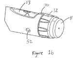
- Fig. 1b is a close-up of the end of the injection device 1. This Fig. shows a locating rib 70 that is located between the viewing window 13 and the dosage knob 12.
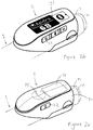
- Fig. 2a is a schematic illustration of an embodiment of a supplementary device 2 to be releasably attached to injection device 1 of Fig. 1a .
- Supplementary device 2 comprises a housing 20 with a mating unit configured and embrace the housing 10 of injection device 1 of Fig. 1a , so that supplementary device 2 sits tightly on housing 10 of injection device 1, but is nevertheless removable from injection device 1, for instance when injection device 1 is empty and has to be replaced.
- Fig. 2a is highly schematic, and details of the physical arrangement are described below with reference to Figure 2b .
- Supplementary device 2 contains optical and acoustical sensors for gathering information from injection device 1. At least a part of this information, for instance a selected dose (and optionally a unit of this dose), is displayed via display unit 21 of supplementary device 2. The dosage window 13 of injection device 1 is obstructed by supplementary device 2 when attached to injection device 1.
- Supplementary device 2 further comprises three user input transducers, illustrated schematically as a button 22. These input transducers 22 allow a user to turn on/off supplementary device 2, to trigger actions (for instance to cause establishment of a connection to or a pairing with another device, and/or to trigger transmission of information from supplementary device 2 to another device), or to confirm something.
- Fig. 2b is a schematic illustration of a second embodiment of a supplementary device 2 to be releasably attached to injection device 1 of Fig. 1a .
- Supplementary device 2 comprises a housing 20 with a mating unit configured and embrace the housing 10 of injection device 1 of Fig. 1a , so that supplementary device 2 sits tightly on housing 10 of injection device 1, but is nevertheless removable from injection device 1.
- Supplementary device 2 further comprises three user input buttons or switches.
- a first button 22 is a power on/off button, via which the supplementary device 2 may for instance be turned on and off.
- a second button 33 is a communications button.
- a third button 34 is a confirm or OK button.
- the buttons 22, 33, 34 may be any suitable form of mechanical switch. These input buttons 22, 33, 34 allow a user to turn on/off supplementary device 2, to trigger actions (for instance to cause establishment of a connection to or a pairing with another device, and/or to trigger transmission of information from supplementary device 2 to another device), or to confirm something.
- Fig. 2c is a schematic illustration of a third embodiment of a supplementary device 2 to be releasably attached to injection device 1 of Fig. 1a .
- Supplementary device 2 comprises a housing 20 with a mating unit configured and embrace the housing 10 of injection device 1 of Fig. 1a , so that supplementary device 2 sits tightly on housing 10 of injection device 1, but is nevertheless removable from injection device 1.
- the dosage window 13 of injection device 1 is obstructed by supplementary device 2 when attached to injection device 1.
- Supplementary device 2 further comprises a touch-sensitive input transducer 35. It also comprises a single user input button or switch 22.
- the button 22 is a power on/off button, via which the supplementary device 2 may for instance be turned on and off.
- the touch sensitive input transducer 35 can be used to trigger actions (for instance to cause establishment of a connection to or a pairing with another device, and/or to trigger transmission of information from supplementary device 2 to another device), or to confirm something.
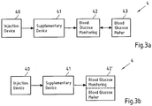
- Figs. 3A and 3b show possible distributions of functions among devices when using a supplementary device (such as the supplementary devices of Fig. 2a and 2b ) together with an injection device.
- a supplementary device such as the supplementary devices of Fig. 2a and 2b
- the supplementary device 41 determines information from injection device 40, and provides this information (e.g. type and/or dose of the medicament to be injected) to a blood glucose monitoring system 42 (e.g. via a wired or wireless connection).
- Blood glucose monitoring system 42 (which may for instance be embodied as desktop computer, personal digital assistant, mobile phone, tablet computer, notebook, netbook or ultrabook) keeps a record of the injections a patient has received so far (based on the ejected doses, for instance by assuming that the ejected doses and the injected doses are the same, or by determining the injected doses based on the ejected doses, for instance be assuming that a pre-defined percentage of the ejected dose is not completely received by the patient). Blood glucose monitoring system 42 may for instance propose a type and/or dose of insulin for the next injection for this patient.
- blood glucose meter 43 may be embodied as a separate device that is configured to receive a small blood probe (for instance on a carrier material) of a patient and to determine the blood glucose level of the patient based on this blood probe.
- Blood glucose meter 43 may however also be a device that is at least temporarily implanted into the patient, for instance in the patient's eye or beneath the skin.
- Fig. 3b is a modified constellation 4' where the blood glucose meter 43 of Fig. 3a has been included into blood glucose monitoring system 42 of Fig. 3a , thus yielding the modified blood glucose monitoring system 42' of Fig. 3b .
- the functionalities of injection device 40 and supplementary device 41 of Fig. 3a are not affected by this modification.
- the functionality of blood glucose monitoring system 42 and blood glucose meter 43 combined into blood glucose monitoring system 42' are basically unchanged, apart from the fact that both are now comprised in the same device, so that external wired or wireless communication between these devices is no longer necessary. However, communication between blood glucose monitoring system 42 and blood glucose meter 43 takes place within system 42'.
- Fig. 4 shows a schematic view of the supplementary device 2 of Fig. 2a in a state where it is attached to injection device 1 of Fig. 1a .
- a plurality of components are comprised. These are controlled by a processor 24, which may for instance be a microprocessor, a Digital Signal Processor (DSP), Application Specific Integrated Circuit (ASIC), Field Programmable Gate Array (FPGA) or the like.
- Processor 24 executes program code (e.g. software or firmware) stored in a program memory 240, and uses a main memory 241, for instance to store intermediate results.
- Main memory 241 may also be used to store a logbook on performed ejections/injections.
- Program memory 240 may for instance be a Read-Only Memory (ROM), and main memory may for instance be a Random Access Memory (RAM).
- processor 24 interacts with a first button 22, via which supplementary device 2 may for instance be turned on and off.
- a second button 33 is a communications button. The second button may be used to trigger establishment of a connection to another device, or to trigger a transmission of information to another device.
- a third button 34 is a confirm or OK button. The third button 34 can be used to acknowledge information presented to a user of supplementary device 2. In embodiments such as those shown in Fig. 2c , two of the buttons 33, 34 may be omitted. Instead, one or more capacitive sensors or other touch sensors are provided.
- Display unit 21 is used to display information to a user of supplementary device 2, for instance on present settings of injection device 1, or on a next injection to be given.
- Display unit 21 may also be embodied as a touch-screen display, for instance to receive user input.
- Processor 24 also controls an optical sensor 25, embodied as an Optical Character Recognition (OCR) reader, that is capable of capturing images of the dosage window 13, in which a currently selected dose is displayed (by way of numbers printed on the sleeve 19 contained in injection device 1, which numbers are visible through the dosage window 13).
- OCR reader 25 is further capable of recognizing characters (e.g. numbers) from the captured image and to provide this information to processor 24.
- unit 25 in supplementary device 2 may only be an optical sensor, e.g. a camera, for capturing images and providing information on the captured images to processor 24. Then processor 24 is responsible for performing OCR on the captured images.
- the numbers shown on a display window 13 of injection device 1 could comprise odd and/or even numbers.
- the processor is capable of transforming the information from the captured image into information to be indicated on the display unit 21 of the supplementary device 2.
- the information indicated on the display unit 21 could be a representation or reproduction of the image or image information.
- the information indicated on the display unit 21 could be an interpretation of the image or image information.
- the display window 13 of injection device 1 may show the numbers "12" and "14" centered which corresponds to a dose of "13 units".
- the processor could control the display to indicate a representation or reproduction of the image, i.e. the display could indicate the numbers "12" and "14".
- the processor 24 may be capable of interpreting the image information and transform it into information to be indicated on the display unit 21. Taking the above example, the image processor 24 may be capable of interpreting the image information as to correspond to a dose of "13 units” and transform the information accordingly. Processor 24 would control the display unit 21 to indicate an interpretation of the image.
- the display unit 21 could for example indicate "13" or "13 units”.
- Processor 24 also controls light-sources such as light emitting diodes (LEDs) 29 to illuminate the dosage window 13, in which a currently selected dose is displayed.
- LEDs light emitting diodes
- a diffuser may be used in front of the light-sources, for instance a diffuser made from a piece of acrylic glass.
- the optical sensor may comprise a lens (e.g. an aspheric lens) leading to a magnification (e.g. a magnification of more than 3:1).
- Processor 24 further controls a photometer 26, that is configured to determine an optical property of the housing 10 of injection device 1, for example a colour or a shading.
- the optical property may only be present in a specific portion of housing 10, for example a colour or colour coding of sleeve 19 or of an insulin container comprised within injection device 1, which colour or colour coding may for instance be visible through a further window in housing 10 (and/or in sleeve 19).
- Information on this colour is then provided to processor 24, which may then determine the type of injection device 1 or the type of insulin contained in injection device 1 (e.g. SoloStar Lantus with purple colour and SoloStar Apidra with blue colour).
- a camera unit may be used instead of photometer 26, and an image of the housing, sleeve or insulin container may then be provided to processor 24 to determine the colour of the housing, sleeve or insulin container by way of image processing.
- one or more light sources may be provided to improve reading of photometer 26.
- the light source may provide light of a certain wavelength or spectrum to improve colour detection by photometer 26.
- the light source may be arranged in such a way that unwanted reflections, for example by dosage window 13, are avoided or reduced.
- a camera unit instead of or in addition to photometer 26, a camera unit may be deployed to detect a code (for instance a bar code, which may for instance be a one- or two-dimensional bar code) related to the injection device and/or the medicament contained therein.
- This code may for instance be located on the housing 10 or on a medicament container contained in injection device 1, to name but a few examples.
- This code may for instance indicate a type of the injection device and/or the medicament, and/or further properties (for instance
- Processor 24 further controls (and/or receives signals from) an acoustic sensor 27, which is configured to sense sounds produced by injection device 1. Such sounds may for instance occur when a dose is dialled by turning dosage knob 12 and/or when a dose is ejected/injected by pressing injection button 11, and/or when a prime shot is performed. These actions are mechanically similar but nevertheless sound differently (this may also be the case for electronic sounds that indicate these actions). Either the acoustic sensor 27 and/or processor 24 may be configured to differentiate these different sounds, for instance to be able to safely recognize that an injection has taken place (rather than a prime shot only).
- Processor 24 further controls an acoustical signal generator 23, which is configured to produce acoustical signals that may for instance be related to the operating status of injection device 1, for instance as feedback to the user.
- an acoustical signal may be launched by acoustical signal generator 23 as a reminder for the next dose to be injected or as a warning signal, for instance in case of misuse.
- Acoustical signal generator may for instance be embodied as a buzzer or loudspeaker.
- a haptic signal generator (not shown) may be used to provide haptic feedback, for instance by way of vibration.
- Processor 24 controls a wireless unit 28, which is configured to transmit and/or receive information to/from another device in a wireless fashion. Such transmission may for instance be based on radio transmission or optical transmission.
- the wireless unit 28 is a Bluetooth transceiver.
- wireless unit 28 may be substituted or complemented by a wired unit configured to transmit and/or receive information to/from another device in a wire-bound fashion, for instance via a cable or fibre connection.
- the units of the data (values) transferred may be explicitly or implicitly defined. For instance, in case of an insulin dose, always International Units (IU) may be used, or otherwise, the used unit may be transferred explicitly, for instance in coded form.
- IU International Units
- Processor 24 receives an input from a pen detection switch 30, which is operable to detect whether the pen 1 is present, i.e. to detect whether the supplementary device 2 is coupled to the injection device 1.
- a battery 32 powers the processor 24 and other components by way of a power supply 31.
- the supplementary device 2 of Fig. 4 is thus capable of determining information related to a condition and/or use of injection device 1. This information is displayed on the display 21 for use by the user of the device. The information may be either processed by supplementary device 2 itself, or may at least partially be provided to another device (e.g. a blood glucose monitoring system).
- a blood glucose monitoring system e.g. a blood glucose monitoring system
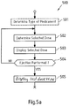
- Figs. 5a-5c are flowcharts of embodiments of methods according to the present invention. These methods may for instance be performed by processor 24 of supplementary device 2 (see Figs. 2b and 4 ), but also by a processor of supplementary device 3 of Fig. 2b , and may for instance be stored in program memory 240 of supplementary device 2, which may for instance take the shape of tangible storage medium 60 of Fig. 6 .
- Fig. 5a shows method steps that are performed in scenarios as shown in Figs. 3a and 3b , where information read by supplementary device 41 from injection device 40 is provided to blood glucose monitoring system 42 or 42' without receiving information back from blood glucose monitoring system 42 or 42'.
- the flowchart 500 starts for instance when the supplementary device is turned on or is otherwise activated.
- a type of medicament for example insulin
- a type of medicament for example insulin
- a code printed on injection device or a component thereof as already described above. Detection of the type of medicament may not be necessary if a patient always takes the same type of medicament and only uses an injection device with this single type of medicament. Furthermore, determination of the type of medicament may be ensured otherwise (e.g. by the key-recess pair shown in Fig. 4 that the supplementary device is only useable with one specific injection device, which may then only provide this single type of medicament).
- a currently selected dose is determined, for instance by OCR of information shown on a dosage window of injection device as described above. This information is then displayed to a user of the injection device in a step 503.
- a prime shot may be differentiated from an actual injection (into a creature) either based on respectively different sounds produced by the injection device and/or based on the ejected dose (e.g. a small dose, for instance less than a pre-defined amount of units, e.g. 4 or 3 units, may be considered to belong to a prime shot, whereas larger doses are considered to belong to an actual injection).
- a small dose for instance less than a pre-defined amount of units, e.g. 4 or 3 units, may be considered to belong to a prime shot, whereas larger doses are considered to belong to an actual injection.
- the determined data i.e. the selected dose and - if applicable - the type of medicament (e.g. insulin)
- the main memory 241 from where it may later be transmitted to another device, for instance a blood glucose monitoring system.
- a differentiation has been made concerning the nature of the ejection for instance if the ejection was performed as a prime shot or as an actual injection, this information may also be stored in the main memory 241, and possibly later transmitted.
- the dose is displayed on the display 21. Also displayed is a time since the last injection which, immediately after injection, is 0 or 1 minute. The time since last dose may be displayed intermittently. For instance, it may be displayed alternately with the name or other identification of the medicament that was injected, e.g. Apidra or Lantus.
- steps 502 and 503 are repeated.
- Fig. 5b shows in more detail exemplary method steps that are performed when the selected dose is determined based on the use of optical sensors only. For instance, these steps may be performed in step 502 of Fig. 5a .
- a sub-image is captured by an optical sensor such as optical sensor 25 of supplementary device 2.
- the captured sub-image is for instance an image of at least a part of the dosage window 13 of injection device 1, in which a currently selected dose is displayed (e.g. by way of numbers and/or a scale printed on the sleeve 19 of injection device 1, which is visible through the dosage window 13).
- the captured sub-image may have a low resolution and/or only show a part of the part of sleeve 19 which is visible through dosage window 13.
- the captured sub- image either shows the numbers or the scale printed on the part of sleeve 19 of injection device 1 which is visible through dosage window 13.
- a step 902 it is determined whether or not there is a change in the captured sub-image.
- the currently captured sub-image may be compared to the previously captured sub-image(s) in order to determine whether or not there is a change.
- the comparison to previously captured sub-images may be limited to the sub-image of the previously captured sub-images that was captured immediately before the current sub-image was captured and/or to the sub-images of the previously captured sub-images that were captured within a specified period of time (e.g. 0.1 seconds) before the current sub-image was captured.
- the comparison may be based on image analysis techniques such as pattern recognition performed on the currently captured sub-image and on the previously captured sub-image.
- Steps 901 and 902 may correspond to a detection of a change in the captured image.
- step 901 is repeated. Otherwise in a step 903, an image is captured by an optical sensor such as optical sensor 25 of supplementary device 2.
- the captured image is for instance an image of the dosage window 13 of injection device 1, in which a currently selected dose is displayed (e.g. by way of numbers and/or a scale printed on the sleeve 19 of injection device 1, which is visible through the dosage window 13).
- the captured image may have a resolution being higher than the resolution of the captured sub-image.
- the captured image at least shows the numbers printed on the sleeve 19 of injection device 1 which are visible through the dosage window 13.
- step 904 optical character recognition (OCR) is performed on the image captured in step 903 in order to recognize the numbers printed on the sleeve 19 of injection device 1 and visible through the dosage window 13, because these numbers correspond to the (currently) selected dose.
- OCR optical character recognition
- the selected dose is determined, for instance by setting a value representing the selected dose to the recognized numbers.
- a step 905 it is determined whether or not there is a change in the determined selected dose and, optionally, whether or not the determined selected dose does not equal zero.
- the currently determined selected dose may be compared to the previously determined selected dose(s) in order to determine whether or not there is a change.
- the comparison to previously determined selected dose(s) may be limited to the previously determined selected dose(s) that were determined within a specified period of time (e.g. 3 seconds) before the current selected dose was determined. If there is no change in the determined selected dose and, optionally, the determined selected dose does not equal zero, the currently determined selected dose is returned/forwarded for further processing (e.g. to processor 24).
- the selected dose is determined if the last turn of the dosage knob 12 is more than 3 seconds ago. If the dosage knob 12 is turned within or after these 3 seconds and the new position remains unchanged for more than 3 seconds, this value is taken as the determined selected dose.
- Fig. 5c shows in more detail method steps that are performed when the selected dose is determined based on the use of acoustical and optical sensors. For instance, these steps may be performed in step 502 of Figs. 5a .
- a sound is captured by an acoustical sensor such as acoustical sensor 27 of supplementary device 2.
- a step 1002 it is determined whether or not the captured sound is a click sound.
- the captured sound may for instance be a click sound that occurs when a dose is dialled by turning dosage knob 12 of injection device 1 and/or when a dose is ejected/injected by pressing injection button 11, and/or when a prime shot is performed. If the captured sound is not a click sound, step 1001 is repeated. Otherwise in a step 1003, an image is captured by an optical sensor such as optical sensor 25 of supplementary device 2. Step 1003 corresponds to step 903 of flowchart 900.
- Step 1004 an OCR is performed on the image captured in step 1003.
- Step 1004 corresponds to step 904 of flowchart 900.
- Step 1005 it is determined whether or not there is a change in the determined selected dose and, optionally, whether or not the determined selected dose does not equal zero. Step 1005 corresponds to step 905 of flowchart 900.
- Fig. 6 is a schematic illustration of a tangible storage medium 600 (a computer program product) that comprises a computer program 601 with program code 602.
- This program code may for instance be executed by processors contained in the supplementary device, for instance processor 24 of supplementary device 2 of Figs. 2 and 4 .
- storage medium 600 may represent program memory 240 of supplementary device 2 of Fig. 4 .
- Storage medium 600 may be a fixed memory, or a removable memory, such as for instance a memory stick or card.
- embodiments of the present invention allow connection of a standard injection device, in particular an insulin device, with a blood glucose monitoring system in a useful and productive way.
- Embodiments of the present invention introduce a supplementary device to allow for this connection, assuming the blood glucose monitoring system has wireless or other communication capabilities.
- the benefits from the connection between the blood glucose monitoring and an insulin injection device are inter alia the reduction of mistakes by the user of the injection device and a reduction of handling steps - no more manual transfer of the injected insulin unit to a blood glucose monitoring is required, in particular to a blood glucose monitoring system with functionality of providing guidance for the next dose based on the last dose injected and latest blood glucose values.
- the user attaches the supplementary device to the pen.
- the supplementary device reads out the injected dose. It may also transfer it to a blood glucose monitoring system with insulin titration capabilities. For patients taking multiple insulins, the supplementary device recognizes the device structure to the insulin type and may also transmit this piece of information to the blood glucose monitoring system.
- the information shown on a display may also converted to a sound signal played to a user through a speaker, for example by a text-to-speech functionality implemented by processor 24 using the acoustical signal generator 23.
- a user with impaired vision may have improved access to the information of supplementary device 2, such as a dialled dose, a recommended dose, a recommended time for administration and/or the like.
- the user inter alia has the following advantages: The user can use the most convenient disposable insulin injector.
- the supplementary device is attachable and detachable (reusable).
- the user may still use the injection device in the same way in which he is used to using it. This is in spite of the fact that the display window 13 is covered by the supplemental device.
- the user can identify that the injection device is the correct one to use, particularly he can check that it contains the correct medicament. This is in spite of the fact that a medicament information label of the injection device is partly covered by the supplemental device.
- Injected dose information may be transferred to the blood glucose monitoring system automatically (no more transfer mistakes). Improved dose guidance may result from this as the blood glucose monitoring system calculates the dose to be taken.
- patients may also be reminded of injecting their next dose by receiving an alarm signal, for instance, after an appropriate time after a first dose of a medicament (for instance insulin or heparin) has been injected.
- a medicament for instance insulin or heparin
- Injected dose information may be transferred to any computerized system, for instance as input for any dose calculation or any other applicable therapeutic guidance calculation, or for the creation of an alarm signal, for instance to remind the user of taking the next dose.
- drug or “medicament”, as used herein, means a pharmaceutical formulation containing at least one pharmaceutically active compound, wherein in one embodiment the pharmaceutically active compound has a molecular weight up to 1500 Da and/or is a peptide, a proteine, a polysaccharide, a vaccine, a DNA, a RNA, an enzyme, an antibody or a fragment thereof, a hormone or an oligonucleotide, or a mixture of the above-mentioned pharmaceutically active compound, wherein in a further embodiment the pharmaceutically active compound is useful for the treatment and/or prophylaxis of diabetes mellitus or complications associated with diabetes mellitus such as diabetic retinopathy, thromboembolism disorders such as deep vein or pulmonary thromboembolism, acute coronary syndrome (ACS), angina, myocardial infarction, cancer, macular degeneration, inflammation, hay fever, atherosclerosis and/or rheumatoid arthritis, wherein in a further
- Insulin analogues are for example Gly(A21), Arg(B31), Arg(B32) human insulin; Lys(B3), Glu(B29) human insulin; Lys(B28), Pro(B29) human insulin; Asp(B28) human insulin; human insulin, wherein proline in position B28 is replaced by Asp, Lys, Leu, Val or Ala and wherein in position B29 Lys may be replaced by Pro; Ala(B26) human insulin; Des(B28-B30) human insulin; Des(B27) human insulin and Des(B30) human insulin.
- Insulin derivates are for example B29-N-myristoyl-des(B30) human insulin; B29-N-palmitoyl-des(B30) human insulin; B29-N-myristoyl human insulin; B29-N-palmitoyl human insulin; B28-N-myristoyl LysB28ProB29 human insulin; B28-N-palmitoyl-LysB28ProB29 human insulin; B30-N-myristoyl-ThrB29LysB30 human insulin; B30-N-palmitoyl- ThrB29LysB30 human insulin; B29-N-(N-palmitoyl-Y-glutamyl)-des(B30) human insulin; B29-N-(N-lithocholyl-Y-glutamyl)-des(B30) human insulin; B29-N-( ⁇ -carboxyheptadecanoyl)-des(B30) human insulin and B29-N-( ⁇ -carbox
- Exendin-4 for example means Exendin-4(1-39), a peptide of the sequence H-His-Gly-Glu-Gly-Thr-Phe-Thr-Ser-Asp-Leu-Ser-Lys-Gln-Met-Glu-Glu-Glu-Ala-Val-Arg-Leu-Phe-Ile-Glu-Trp-Leu-Lys-Asn-Gly-Gly-Pro-Ser-Ser-Gly-Ala-Pro-Pro-Pro-Ser-NH2.
- Exendin-4 derivatives are for example selected from the following list of compounds:
- Hormones are for example hypophysis hormones or hypothalamus hormones or regulatory active peptides and their antagonists as listed in Rote Liste, ed. 2008, Chapter 50, such as Gonadotropine (Follitropin, Lutropin, Choriongonadotropin, Menotropin), Somatropine (Somatropin), Desmopressin, Terlipressin, Gonadorelin, Triptorelin, Leuprorelin, Buserelin, Nafarelin, Goserelin.
- Gonadotropine Follitropin, Lutropin, Choriongonadotropin, Menotropin
- Somatropine Somatropin
- Desmopressin Terlipressin
- Gonadorelin Triptorelin
- Leuprorelin Buserelin
- Nafarelin Goserelin.
- a polysaccharide is for example a glucosaminoglycane, a hyaluronic acid, a heparin, a low molecular weight heparin or an ultra low molecular weight heparin or a derivative thereof, or a sulphated, e.g. a poly-sulphated form of the above-mentioned polysaccharides, and/or a pharmaceutically acceptable salt thereof.
- An example of a pharmaceutically acceptable salt of a poly-sulphated low molecular weight heparin is enoxaparin sodium.
- Antibodies are globular plasma proteins (-150 kDa) that are also known as immunoglobulins which share a basic structure. As they have sugar chains added to amino acid residues, they are glycoproteins.
- the basic functional unit of each antibody is an immunoglobulin (Ig) monomer (containing only one Ig unit); secreted antibodies can also be dimeric with two Ig units as with IgA, tetrameric with four Ig units like teleost fish IgM, or pentameric with five Ig units, like mammalian IgM.
- Ig immunoglobulin
- the Ig monomer is a "Y"-shaped molecule that consists of four polypeptide chains; two identical heavy chains and two identical light chains connected by disulfide bonds between cysteine residues. Each heavy chain is about 440 amino acids long; each light chain is about 220 amino acids long. Heavy and light chains each contain intrachain disulfide bonds which stabilize their folding. Each chain is composed of structural domains called Ig domains. These domains contain about 70-110 amino acids and are classified into different categories (for example, variable or V, and constant or C) according to their size and function. They have a characteristic immunoglobulin fold in which two ⁇ sheets create a "sandwich" shape, held together by interactions between conserved cysteines and other charged amino acids.
- Ig heavy chain There are five types of mammalian Ig heavy chain denoted by ⁇ , ⁇ , ⁇ , ⁇ , and ⁇ .
- the type of heavy chain present defines the isotype of antibody; these chains are found in IgA, IgD, IgE, IgG, and IgM antibodies, respectively.
- Distinct heavy chains differ in size and composition; ⁇ and ⁇ contain approximately 450 amino acids and ⁇ approximately 500 amino acids, while ⁇ and ⁇ have approximately 550 amino acids.
- Each heavy chain has two regions, the constant region (C H ) and the variable region (V H ).
- the constant region is essentially identical in all antibodies of the same isotype, but differs in antibodies of different isotypes.
- Heavy chains ⁇ , ⁇ and ⁇ have a constant region composed of three tandem Ig domains, and a hinge region for added flexibility; heavy chains ⁇ and ⁇ have a constant region composed of four immunoglobulin domains.
- the variable region of the heavy chain differs in antibodies produced by different B cells, but is the same for all antibodies produced by a single B cell or B cell clone.
- the variable region of each heavy chain is approximately 110 amino acids long and is composed of a single Ig domain.
- a light chain has two successive domains: one constant domain (CL) and one variable domain (VL).
- CL constant domain
- VL variable domain
- the approximate length of a light chain is 211 to 217 amino acids.
- Each antibody contains two light chains that are always identical; only one type of light chain, ⁇ or ⁇ , is present per antibody in mammals.
- variable (V) regions are responsible for binding to the antigen, i.e. for its antigen specificity.
- VL variable light
- VH variable heavy chain
- CDRs Complementarity Determining Regions
- an "antibody fragment” contains at least one antigen binding fragment as defined above, and exhibits essentially the same function and specificity as the complete antibody of which the fragment is derived from.
- Limited proteolytic digestion with papain cleaves the Ig prototype into three fragments. Two identical amino terminal fragments, each containing one entire L chain and about half an H chain, are the antigen binding fragments (Fab).
- the Fc contains carbohydrates, complement-binding, and FcR-binding sites.
- F(ab')2 is divalent for antigen binding.
- the disulfide bond of F(ab')2 may be cleaved in order to obtain Fab'.
- the variable regions of the heavy and light chains can be fused together to form a single chain variable fragment (scFv).
- Pharmaceutically acceptable salts are for example acid addition salts and basic salts.
- Acid addition salts are e.g. HCI or HBr salts.
- Basic salts are e.g. salts having a cation selected from alkali or alkaline, e.g. Na+, or K+, or Ca2+, or an ammonium ion N+(R1)(R2)(R3)(R4), wherein R1 to R4 independently of each other mean: hydrogen, an optionally substituted C1-C6-alkyl group, an optionally substituted C2-C6-alkenyl group, an optionally substituted C6-C10-aryl group, or an optionally substituted C6-C10-heteroaryl group.
- solvates are for example hydrates.
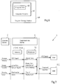
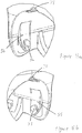
- the supplemental device 2 is attached to the injection pen 1 close to the dosage knob 12 with the display 21 uppermost in the orientation shown (which is the same for all of Figs. 8 to 14 ).
- the plane of the display 21 lies generally transverse to the longitudinal axis of the injection device 1, and is perpendicular to the page of Figures 8 , 9 , 10 , 12 , 13 and 14 .
- a closure 68 extends from a shaft 59 of a hinge, the closure extending underneath the injection pen.
- the closure 68 is connected to the supplemental device 2 on the right side (looking at the injection device 1 with the injection button closest to the viewer), extends underneath the injection pen 1 and connects with the supplemental device on the left side thereof.
- the supplemental device 2 of these illustrated embodiments includes two features that contribute to correct alignment of the supplemental device 2 on the injection device 1, and one feature that results in securing of the supplemental device 2 to the injection device 1.
- the features that contribute to correct alignment of the supplemental device 2 on the injection device 1 can be termed alignment arrangements.
- the features that contribute to securing of the supplemental device 2 to the injection device 1 can be termed a securing arrangement.
- the correct alignment of the supplemental device 2 on the injection device 1, ensures that the OCR reader 25 is correctly aligned with the dosage window 13. Correct alignment allows correct operation and reliable readings. Ensuring that there can be correct alignment between the supplemental device 2 and the injection device 1 in use allows a simpler design for the OCR reader 25, in particular because it does not need to be designed to be able to accommodate different alignments between the devices 1, 2.
- the first alignment feature is a locating channel 71.
- the locating channel 71 is located at the uppermost part of an injection device receiving channel 58 that is defined between the main body of the supplemental part and the closure 68 when in the closed position.
- the locating channel 71 is best shown in Figures 11a and 11b . From here, it will be seen that the locating channel is formed at the end of the supplemental device that is closest to the dosage knob 12 when the supplemental device 2 is fitted to the injection device 1.
- the locating rib 70 is located between the display window 13 and the dosage knob 12. In this example, the locating rib 70 extends for the whole of the distance between the display window 13 and the dosage knob 12. In other examples, the locating rib is shorter. The locating rib 70 is taller at the end that is adjacent the dosage knob 12 and tapers down to a zero height at the junction with the display window 13. As can be seen from Figure 1b , the taper of the uppermost edge of the locating rib 70 is slightly curved. The gradient of the taper is less at the part of the locating rib 70 that is closest to the dosage knob 12 and is greater along the locating rib to the location of the display window 13. The shape of the locating rib 70 is such that the gradient continually increases as one moves from the position of the locating rib 70 that is adjacent to the dosage knob 12 to the position of the locating rib 70 that is adjacent the display window 13.
- the thickness of the locating rib 70 varies along the length of the locating rib 70.
- the thickness of the locating rib 70 is greatest at the end adjacent the dosage knob 12 and is least at the end adjacent the display window 13.
- the thickness of the locating rib 70 gradually decreases as one moves from the end of the locating rib adjacent the dosage knob 12 to the end of the locating rib that is adjacent the display window 13.
- the cross-section of the locating rib is of a rounded triangle.
- the cross-section of the locating rib 70 is approximately the same for its entire length, although of course the size varies.
- the locating channel 71 is dimensioned so as to correspond closely to the shape and size of the locating rib 70 that is present on the injection pen 1.
- the locating channel 71 has a size and shape that corresponds closely to the size and shape of the locating rib 70.
- the locating channel 71 is slightly larger than the locating rib so as to ensure that the locating rib can be located within the locating channel 71.
- the corresponding sizes ensure that the two features mate together. This assists in ensuring correct positioning of the supplemental device 2 on the injection device 1.
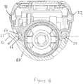
- the injection pen 1 is provided with indents on either side of its body at locations close to the dosage knob 12.
- a left side indent 52 is shown.
- a right indent 51 which is shown in Figures 10 and 12 , is located in a corresponding position on the right side of the injection pen 1.
- the left and right indents 51, 52 are relatively shallow depressions.
- the indents 51, 52 have sloping sides, that is the sides of the indents 51, 52 are not parallel. Also, they are not radial with respect to the longitudinal axis of the injection pen 1.
- the slope of the sides of the left and right indents 51, 52 is different for different parts of the indents.
- the gradient of the slope of the sides of the indents is less at the part of the indents that is furthest from the display window 13 and is greatest at the part of the indents 51, 52 that is closest to the display window 13.
- the slope of the indents changes between these two extremes, for instance in a linear fashion.
- the slope of the sides of the indent may for instance be between 30 and 70 degrees at the part that is furthest from the display window 13.
- the slope may for instance be between 60 and 80 degrees for the part that is closest to the display window 13.
- the greater angle of slope at the part closer to the display window 13 aids engagement of a face of a protuberance within the indent 51, 52 in such a way as to provide some resistance against removal of the supplemental device 2 in a direction radial to the longitudinal axis of the injection device 1.
- the left and right protuberances 53, 54 are shaped to correspond to the shapes of the right and left indents 51, 52 respectively. In this way, the right and left protuberances 53, 54 fit within the right and left indents 51, 52 respectively when the supplementary device 2 is correctly positioned on the injection pen 1.
- the external dimensions of the right and left protuberances 53, 54 are slightly smaller than the internal dimensions of the right and left indents 51, 52 so as to ensure that the protuberances fit within their respective indent.
- the left and right protuberance 52 is shaped to correspond closely to the shape of the right indent 51.
- the right protuberances 53 fits snugly within the right indent 51 when the supplementary device 2 is correctly positioned on the injection pen 1.
- the left protuberance 54 is shaped similarly to the right protuberance 53, although it is less tall. Put another way, it is like the right protuberance 53 but with the top part missing or cut off. This is the reason for the end face of the left protuberance 54 having a larger area than the right protuberance 53.
- the different sizes for the protuberances 53, 54 helps the protuberances find engagement within the indents 51, 52.
- the right protuberance 53 can be consider to be a master to the left protuberance, which is a slave.
- the right protuberance 53 is located at the end of the right arm 55, which is best shown in Figure 11b .
- the left protuberance 54 is located at the end of the left arm 56.
- the right and left arms 55, 56 depend substantially vertically from the body 20 of the supplementary device 2.
- the right and left arms 55, 56 are thus formed on either side of the injection device receiving channel 58.
- a biasing feature 67 in the form of a u-shaped spring, is coupled to each of the right and left arms 55, 56.
- the effect of the spring 67 is to bias the right and left arms into a certain position.
- the position into which the right and left arms 55, 56 are biased is such that the distance between the innermost surfaces of the right and left protuberances 53, 54 is slightly less than the distance between the bottoms of the right and left indents 51, 52.
- the effect of the spring 67 is to resist movement of the protuberances 53, 54 and the arms 55, 56, away from one another.
- the supplemental device 2 is located with respect to the injection pen 1 such that the ends of the right and left arms 55, 56, in particular the protuberances 53, 54, are just touching the housing 10 of the injection pen 1.
- the protuberances 53, 54 here contact the housing to the left and right sides of the display window 13.
- the left and right arms 55, 56 are present behind flaps 60 that depend from the supplemental device 2 on both the left and right sides.
- the flaps, or protecting walls 60 extend slightly further in a downwards direction than the arms.
- the flaps 60 are formed of transparent material. This allows a user to be able to view the locations of the arms 55, 56 relative to the indents 51, 52, which may help them to locate the supplemental device 2 correctly on the injection device 1.
- Figure 8 shows the location of the left indent 52 in dotted form, to highlight the location of the arms, 55, 56 as well as the indents 51, 52, although the arms are not shown in this view.
- the user In order to mate the supplemental device 2 with the injection device 1, the user first arranges the supplemental device 2 with respect to the injection device 1 as shown in Figure 10 , and then applies a force downwards on the supplemental device 2 while at the same time applying a force upwards on the injection device 1. This places force on the protuberances 53, 54, and thus the right and left arms 55, 56. As the injection device 1 and the supplemental device 2 move closer together, the force results in the arms being moved apart, against the resilience of the spring 67. This causes the spring 67 to apply a reaction force, which resists entry of the injection device 1 into the injection device receiving channel 58.
- the protuberances 53, 54 become aligned with the left and right indent 51, 52 and, due to the resilience of the spring 67, become engaged with the indents. Engagement provides haptic and audio feedback as the protuberances 53, 54 click or snap into the indents 51, 52. The feedback is enhanced by the force provided by the resilience of the spring 67.
- one of the protuberances 53, 54 will engage with the higher one of the indents before the other one of the protuberances reaches the other indent.
- the protuberance and indent that first meet become engaged, and present significant resistance to further movement of that protuberance relative to that indent.
- the tendency is naturally for the injection device 1 to be rotated relative to the supplemental device such that the other indent meets the other protuberance. Once the other indent meets the other protuberance, they mate together and considerable resistance is presented against further movement of the injection pen 1 relative to the supplemental device 2.
- the experience of the user is such that the injection pen 1 and the supplemental device 2 seem to move together initially with little or no rotation. Haptic and audio feedback is then provided when the first protuberance meets the corresponding indent, and after this point the injection device 1 seems to roll into place within the injection device receiving channel 58 until the other protuberance is received in the other indent, at which point further haptic and audio feedback is provided to the user.
- the injection device 1 is fully located within the injection device receiving channel 58 as shown in Figure 12 .
- the outermost surface of the display window 13 is generally aligned with a lowermost surface of the upper part of the supplemental device 2.
- This supplemental device 2 is shaped such that the injection device 1 fits snugly within the injection device receiving channel 58 and there are multiple points or areas of contact between the exterior surface of the housing 10 of the injection device 1 and the lowermost surface of the supplemental device 2 when the supplemental device and the injection pen 1 are in this relative position. Even in the absence of the mating of the protuberances 53, 54 with the indents 51, 52 at this point, the user would notice that there is a natural tendency for the injection pen 1 to sit at this location within the supplemental device 2.
- the locating rib 70 is engaged within the locating channel 71. Correct alignment of the supplemental device 2 with respect to the injection device 1 is thus provided in two ways: firstly, by the location of the locating rib 70 within the locating channel 71 and secondly by the locating of the protuberances 53, 54 within the indents 51, 52.
- the locating rib 70 does not fit within the locating channel 71.
- the supplemental device 2 is prevented from being located fully over the injection pen 1 by the locating rib 70 resting against a surface of the supplemental device 2 that is in some way distal from the correct location within the locating channel 71.
- the ends of the protuberances 53, 54 have passed the halfway point of the circumference of the housing 10 of the injection device 1 and thus the spring 67 results in the injection device 1 being biased towards the supplemental device 2 so as to be located within the injection device receiving channel 58.
- a user would know that the supplemental device 2 had not mated correctly with the injection pen 1 because they would not have received any haptic feedback from the mating of the protuberances 53, 54 with the indents 51, 52. They would also notice that the end of the supplemental device that is closest to the dosage knob 12 was separated from the injection pen 1 by a distance greater than the separation of the supplemental device 2 from the injection pen 1 at the end of the supplemental device 2 distal from the dosage knob 12. In this situation, the user can engage the supplemental device 2 and the injection pen 1 simply by exerting a force against the supplemental device 2 and the injection pen 1 such as to move the supplemental device 2 leftwards in the direction shown in Figure 8 . This can be achieved in a one-handed fashion or in a two-handed fashion.
- the locating rib and the locating channel become more and more engaged.
- the spring force provided by the spring 67 may assist relative movement of the supplemental device 2 and the injection device 1 in this manner.
- the end of the supplemental device 2 that is closest to the dosage knob 12 moves down towards the injection device 1. This movement continues until the locating rib 70 is completely within the locating channel 71, at which point the right and left protuberances 53, 54 also engage with the right and left indents 51, 52 respectively.
- haptic feedback is provided by the mating of the protuberances 53, 54 with the indents 51, 52 and the user can determine that the supplemental device 2 and the injection device 1 are properly located with respect to one another.
- the user locates the supplemental device onto the injection pen 1 such that the supplemental device is to the left of the position shown in Figure 8 , mating between the supplemental device 2 and the injection pen 1 will not occur. In this case, the locating rib 70 will not prevent the supplemental device 2 from being located flat against the injection pen 1. A user, noticing this, will know that the supplemental device 2 is located too far from the dosage knob 12. The user can engage the supplemental device 2 with the injection pen 1 simply by moving the supplemental device 2 relative to the injection device 1 such as to move the supplemental device 2 rightwards in the direction shown in Figure 8 .
- the locating rib 70 is aligned with the locating channel 71 when the end of the locating rib 70 that is closest to the display window 13, the smallest end of the locating rib 70 will enter the mouth, being the large open end, of the locating channel 71.
- the supplemental device still is located against the surface of the injection device 1, with the injection device 1 being fully located within the injection device receiving channel 58. Because of the action of the spring 67, the injection device 1 is biased into the injection device receiving channel 58 against the supplemental device 2 at this stage.
- the narrowest end of the locating rib 70 will engage with a side of the locating channel. Further relative movement of the supplemental device 2 and the injection device 1 in a longitudinal direction results in a reactive force being applied between the locating rib and a wall of the locating channel 71, biasing the supplemental device 2 and the injection device 1 towards being in full alignment. This occurs until the locating rib 70 is fully engaged within the locating channel 71, at which point the right and left protuberances 53, 54 also engage with the right and left indents 51, 52. At this point, the supplemental device 2 and the injection device 1 are fully engaged with one another.
- the supplemental device 2 is provided with a closure 68, which has a primary function of clamping the supplemental device 2 to the injection pen 1 when the two devices are mated with one another.
- the closure 68 has an innermost surface that coincides with the curved surface of an imaginary cylinder.
- the diameter of the cylinder is the same as the external dimension of the housing 10 of the injection device 1.
- the closure 68 forms a snug fit against the lowermost part of the housing 10 of the injection device 1 when the supplemental device 2 is in place on the injection device 1.
- the closure 68 is moveable between an open position, shown in Figure 13 , and a closed position, shown in Figure 14 .
- the closure 68 is located next to the arm protecting walls 60, in a direction opposite the arm protecting walls 60 to the dosage knob 12.
- the closure 68 has a dimension in a longitudinal axis of the injection pen 1 that is approximately 60% of the length dimension of the supplemental device 2.
- the length of the closure 68 in a longitudinal direction of the injection pen 1 may take a value anywhere between 30 and 80% of the length of the supplemental device 2, and preferably between 40 and 70% of the length of the supplemental device 2.
- the material of the closure 68 has a generally uniform thickness.
- the external surface of the closure 68 that is the surface that is furthest from the longitudinal axis of the injection pen 1 when the supplemental device 2 is mated with the injection pen 1, is generally cylindrical, or at least takes the form of part of a cylinder.
- the closure 68 is provided with two cutaways 72, 73.
- the cutaways 72, 73 extend from an edge of the closure 68 that is furthest from the shaft 59 of the hinge formed at the other side of the supplemental device 2.
- the cutaways 72, 73 extend from this edge in a direction that is generally circumferential with respect to the injection pen 1.
- the length of the cutaways is approximately equal to 1/6 or 1/5 of the circumference of the circle on which the closure 68 generally lies.
- the cutaways 72, 73 define a tab 61.
- the tab 61 is connected to the main part of the closure 68 at a location between the lowermost ends of the cutaways 72, 73.
- a free end 63 of the tab 61 is located between the uppermost ends of the cutaways 72, 73.
- the free end 63 of the tab 61 is curved so as to extend away from the longitudinal axis of the injection pen 1 by a greater extent at a point that is central between the cutaways 72, 73. This allows a user better to be able to locate a digit on the free end 63 of the tab 61 so as to be able to pull the free end 63 in a direction that is downwards and leftwards in Figure 14 .
- a latching edge 64 On the inside surface of the tab 61 is provided a latching edge 64, which is best seen in Figures 9 , 13 and 14 .
- the latching edge 64 is provided at a junction between a latching face and another face.
- the latching edge 64 extends for the width of the tab 61.
- the latching face is in a plane that extends approximately radially with respect to the longitudinal axis of the injection 1 when the closure 68 is in the closed position, as shown in Figure 14 .
- the latching edge 64 is engaged with a latch engaging face 66 that is provided as a part of the uppermost portion of the supplemental device 2, i.e. is provided as a portion of the supplemental device 2 that is not part of the closure 68.
- the latch engaging face 66 is provided in a plane that is generally the same orientation as the plane of the latching face when the closure 68 is in the closed position.
- the user may secure the supplemental device 2 to the injection pen 1.
- This is achieved by the user moving the closure 68 from the position shown in Figure 9 , in which the injection device receiving channel 58 is open for inclusion of the injection pen 1 therein, and rotating the closure 68 around the shaft 59 of the hinge so as to move the free end 63 of the tab 61 towards the latch engaging face. Movement continues until contact is made between the innermost part of the latching edge 64 against a guide surface 65, which is located just beneath (as shown in the Figures) the latch engaging face 66.
- the guide surface 65 is angled approximately tangentially to the outside surface of the housing 10 of the injection pen 1.
- the tendency of the closure 68 to adopt the shape shown in Figure 13 provides a spring force between the end of the tab 61 and the guide surface 65.
- the closure 68 deforms resiliently so as to increase the separation between the free end 63 of the tab 61 and the hinge 59. This allows the edge of the latching edge 64 to slide over the guide surface 65. This continues until the latching edge 64 becomes aligned with the edge between the guide surface 65 and the latch engaging face 66, at which point the latching edge 64 and the latching face engage within the channel that is formed against the latch engaging face 66.
- Movement of the supplemental device 2 along the longitudinal axis of the injection pen 1 is inhibited by the mating between the protuberances 53, 54 and the indents 51, 52. Additionally, movement of the supplemental device 2 in a rightwards direction as shown in Figure 8 is further prevented by the locating rib 70 acting against the body 20 of the supplemental device 2.
- the supplemental device 2 is provided with one or more surfaces that are specifically configured to oppose sliding of the supplemental device 2 on the exterior surface of the housing 10 of the injection device 1.
- surfaces of the supplemental device 2 that contact the injection device 1 when the supplemental device 2 is engaged with the injection device 1 as shown in Figure 8 may be provided with a high friction coating or may be formed of a high friction material.
- Such materials include rubberised materials, silicone, materials with roughened surfaces, materials which have some adhesive properties, and such like.
- Such surfaces may include one or more of an innermost surface of the closure 68, and/or a lowermost surface of the upper part of the supplementary device. These surfaces may extend for the whole of the surface of the supplementary device 2 that contacts the housing 10 of the injection device 1 during use, or may extend over only a part of the relevant surfaces.
- the user In order to remove the supplemental device 2 from the injection pen 1, the user first places a digit, for instance a finger or thumb, on the uppermost surface of the free end 63 of the tab 61. The user then can exert a force downwards and leftwards as shown in Figure 14 . When the force applied is sufficient, the closure 68 will deform to a point where the latching edge 64 is no longer engaged with the latch engaging face 66. At this point, the closure 68 can be moved downwards, pivoting around the shaft 59 of the hinge. Indeed, if the injection device 1 is held at the orientation shown in Figure 14 , then gravity will assist the movement of the closure 68 in this direction.
- a digit for instance a finger or thumb
- the supplemental device 2 is no longer clamped to the injection device 1. In this position, the supplemental device 2 is held onto the injection device 1 only by the mating of the protuberances 53, 54 and the indents 51, 52.
- the user may grasp the supplemental device 2 in one hand and apply a force to it in a direction upwards as shown in Figure 8 .
- the force applied is sufficient to overcome the spring and friction forces, the sloping surface of the indents 51 and 52 that are uppermost in Figure 10 slide over the corresponding sloping surfaces of the protuberances 53, 54.
- the left and right arms 55, 56 are moved apart, against the bias of the spring 67.
- the protuberances 53, 54 are free of the indents 51, 52, the user experiences relatively little resistance as the supplemental device 2 is removed from the injection pen 1.
- the cooperation between the locating rib 70 and the locating channel 71 does not present any obstacle to separating the supplemental device 2 and the injection pen 1 in this way.
- the user may grasp the supplemental device and move it in a direction that is rightwards in Figure 8 .
- the locating rib and the locating channel 71 cooperate to assist in removal of the protuberances from the indents 51, 52.
- the locating rib 70 slides deeper into the locating channel, which results in an upwards force being applied to the supplemental device 2 relative to the injection pen 1. This upwards force then assists in overcoming the spring and friction forces needed to remove the protuberances 53, 54 from the indents 51, 52.
- the left and right arms 55, 56 are restrained on either side by the main body of the supplemental device 2. This can prevent or inhibit movement of the left and right arms 55, 56 in a direction that is perpendicular to the page of Figure 10 . This assists in maintaining the supplemental device 2 in the correct location after installation on the injection pen 1 even in the presence of (low) forces acting to move the supplemental device 2 along the longitudinal axis of the injection pen 1.
- the arms 55, 56 can be termed support members because they support the protuberances.
- the left and right arms 55, 56 are free to move slightly in a direction that is perpendicular to the page of Figure 10 .
- the body 20 of the supplemental device 2 can move relative to the housing 10 of the injection pen 1 whilst the protuberances 53, 54 remain fully engaged within the indents 51, 52. This prevents the engagement between the protuberances 53, 54 and the indents 51, 52 significantly restricting movement of the supplemental device 2 in the rightwards direction shown in Figure 8 , at least until the interaction between the locating rib 70 and the locating channel 71 causes the supplemental device 2 to be moved upwards relative to the injection pen 1.
- the left and right arms 55, 56 are configured such that they are significantly resistant to movement in a direction that is perpendicular to the page of Figure 10 .
- the arms 55, 56 may include a triangular structure with the protuberance at one corner and fixings to the main body of the supplemental device 2 at the other two corners. These two other corners may be separated in the axial length of the supplemental device 2.
- the triangular structure may comprise three limbs or it may be sheet-like. It may be planar or it may be curved.
- the locating rib 70 and the locating channel 71 are absent. In these embodiments, the correct alignment between the supplemental device 2 and the injection pen 1 is provided by mating of the protuberances 53, 54 and the indents 51, 52.
- the right and left arms 55, 56 and the protuberances 53, 54 are absent.
- the correct alignment between the supplemental device 2 and the injection device 1 is provided by the locating rib 70 and the locating channel 71.
Landscapes
- Engineering & Computer Science (AREA)
- Health & Medical Sciences (AREA)
- General Engineering & Computer Science (AREA)
- Public Health (AREA)
- General Health & Medical Sciences (AREA)
- Mechanical Engineering (AREA)
- Life Sciences & Earth Sciences (AREA)
- Biomedical Technology (AREA)
- Medical Informatics (AREA)
- Veterinary Medicine (AREA)
- Animal Behavior & Ethology (AREA)
- Heart & Thoracic Surgery (AREA)
- Primary Health Care (AREA)
- Epidemiology (AREA)
- Vascular Medicine (AREA)
- Anesthesiology (AREA)
- Hematology (AREA)
- Physics & Mathematics (AREA)
- Bioinformatics & Cheminformatics (AREA)
- Medicinal Chemistry (AREA)
- Chemical & Material Sciences (AREA)
- Optics & Photonics (AREA)
- Emergency Medicine (AREA)
- Biophysics (AREA)
- Pathology (AREA)
- Molecular Biology (AREA)
- Surgery (AREA)
- Business, Economics & Management (AREA)
- General Business, Economics & Management (AREA)
- Infusion, Injection, And Reservoir Apparatuses (AREA)
Claims (12)
- Zusatzvorrichtung (2) zum Anbringen an einer Injektionsvorrichtung (1), wobei die Zusatzvorrichtung Folgendes aufweist:eine Ausrichtungsanordnung (53, 54; 71) zur Gewährleistung einer vorbestimmten Positionsbeziehung zwischen der Zusatzvorrichtung und der Injektionsvorrichtung undeine Befestigungsanordnung (51-56; 63-68) zum Befestigen der Zusatzvorrichtung an der Injektionsvorrichtung,wobei eine optische Leseanordnung (25, 29) auf eine Anzeige der Injektionsvorrichtung gerichtet ist und diese zumindest teilweise abdeckt, wenn die vorbestimmte Positionsbeziehung zwischen der Zusatzvorrichtung und der Injektionsvorrichtung vorliegt,wobei die Ausrichtungsanordnung einen ersten und einen zweiten Vorsprung (53, 54) aufweist, die an einem ersten bzw. zweiten Stützglied (55, 56) angeordnet sind, wobei die Zusatzvorrichtung so ausgestaltet ist, dass die Vorsprünge in Vertiefungen (52) an der Injektionsvorrichtung in Eingriff gelangen, wenn die vorbestimmte Positionsbeziehung vorliegt,wobei die Zusatzvorrichtung einen Hauptkörper hat, der einen Injektionsvorrichtungsaufnahmekanal definiert, wobei die Vorsprünge beiderseits des Injektionsvorrichtungsaufnahmekanals angeordnet sind und wobei die Stützglieder aufeinander zu vorgespannt sind,wobei die Befestigungsanordnung einen Verschluss (68) aufweist, der über den Injektionsvorrichtungsaufnahmekanal anbringbar ist, so dass eine Bewegung der Injektionsvorrichtung relativ zu der Zusatzvorrichtung in eine orthogonal zu der Längsachse des Injektionsvorrichtungsaufnahmekanals verlaufende Richtung gesperrt ist, undwobei die Vorsprünge so ausgestaltet sind, dass eine Bewegung der Zusatzvorrichtung entlang der Längsachse des Injektionsvorrichtungsaufnahmekanals gesperrt ist, wenn sie bei Vorliegen der vorbestimmten Positionsbeziehung in den Vertiefungen (52) an der Injektionsvorrichtung in Eingriff gelangen.
- Zusatzvorrichtung nach Anspruch 1, wobei die Ausrichtungsanordnung und die Befestigungsanordnung separate Anordnungen sind.
- Zusatzvorrichtung nach einem der beiden vorhergehenden Ansprüche, wobei die Ausrichtungsanordnung einen Lokalisierungskanal (71) in einem Hauptkörper der Zusatzvorrichtung aufweist, wobei der Lokalisierungskanal dazu ausgestaltet ist, mit einer Lokalisierungsrippe (70) an der Injektionsvorrichtung zusammenzuwirken, und optional wobei der Lokalisierungskanal an einem Ende des Hauptkörpers der Zusatzvorrichtung angeordnet ist.
- Zusatzvorrichtung nach einem der vorhergehenden Ansprüche, wobei die Vorsprünge geneigte Seiten haben und wobei eine Neigung einer Seite jedes Vorsprungs, die dem Boden des Injektionsvorrichtungsaufnahmekanals am nächsten liegt, größer als eine Neigung einer Seite des Vorsprungs ist, die von dem Boden des Injektionsvorrichtungsaufnahmekanals am weitesten entfernt liegt.
- Zusatzvorrichtung nach einem der vorhergehenden Ansprüche, wobei der Verschluss entfernbar über den Injektionsvorrichtungsaufnahmekanal anbringbar ist.
- Zusatzvorrichtung nach Anspruch 5, wobei die Befestigungsanordnung an einer ersten Seite des Injektionsvorrichtungsaufnahmekanals beweglich an dem Hauptkörper angebracht ist oder wobei die Befestigungsanordnung an einer ersten Seite des Injektionsvorrichtungsaufnahmekanals an dem Hauptkörper angelenkt ist.
- Zusatzvorrichtung nach Anspruch 5 oder Anspruch 6, wobei die Befestigungsanordnung mit dem Hauptkörper der Zusatzvorrichtung an einer zweiten Seite des Injektionsvorrichtungsaufnahmekanals mittels einer Einrastverriegelungsanordnung entfernbar verbindbar ist.
- Zusatzvorrichtung nach einem der vorhergehenden Ansprüche, wobei die Stützglieder mittels des Verschlusses aufeinander zu vorgespannt sind.
- System, aufweisend eine Zusatzvorrichtung nach einem der vorhergehenden Ansprüche und eine Injektionsvorrichtung.
- System nach Anspruch 9, wobei die Zusatzvorrichtung so angeordnet ist, dass sie den Benutzerzugriff auf einen Dosierungsknopf oder einen Injektionsknopf der Injektionsvorrichtung nicht versperrt, wenn die vorbestimmte Positionsbeziehung zwischen der Zusatzvorrichtung und der Injektionsvorrichtung vorliegt, und/oder wobei die Zusatzvorrichtung so angeordnet ist, dass sie ein an der Injektionsvorrichtung vorgesehenes Medikamentinformationsetikett nicht vollständig verdeckt, wenn die vorbestimmte Positionsbeziehung zwischen der Zusatzvorrichtung und der Injektionsvorrichtung vorliegt, und/oder wobei die Injektionsvorrichtung zumindest einen Vorsprung aufweist, der mit der Ausrichtungsanordnung der Zusatzvorrichtung zusammenwirkt, und optional wobei der zumindest eine Vorsprung eine Lokalisierungsrippe aufweist und/oder wobei die Injektionsvorrichtung (1) zumindest eine Vertiefung aufweist, die mit der Ausrichtungsanordnung der Zusatzvorrichtung (2) zusammenwirkt.
- System nach Anspruch 9 oder Anspruch 10, wobei die Injektionsvorrichtung (1) eine Lokalisierungsrippe (70) und zwei Vertiefungen (51, 52) aufweist, die mit einem Lokalisierungskanal (71) bzw. Vorsprüngen (53, 54) der Zusatzvorrichtung (2) in Eingriff stehen.
- Verwendung einer Zusatzvorrichtung nach einem der Ansprüche 1 bis 8.
Priority Applications (1)
| Application Number | Priority Date | Filing Date | Title |
|---|---|---|---|
| EP13709047.8A EP2814546B1 (de) | 2012-02-13 | 2013-02-08 | Stiftartiger injektor und elektronische aufsteckvorrichtung dafür |
Applications Claiming Priority (5)
| Application Number | Priority Date | Filing Date | Title |
|---|---|---|---|
| EP12155197 | 2012-02-13 | ||
| US201261604699P | 2012-02-29 | 2012-02-29 | |
| EP12161433 | 2012-03-27 | ||
| PCT/EP2013/052506 WO2013120774A1 (en) | 2012-02-13 | 2013-02-08 | Pen-type injection device and electronic clip-on module therefor |
| EP13709047.8A EP2814546B1 (de) | 2012-02-13 | 2013-02-08 | Stiftartiger injektor und elektronische aufsteckvorrichtung dafür |
Publications (2)
| Publication Number | Publication Date |
|---|---|
| EP2814546A1 EP2814546A1 (de) | 2014-12-24 |
| EP2814546B1 true EP2814546B1 (de) | 2020-06-03 |
Family
ID=48983561
Family Applications (1)
| Application Number | Title | Priority Date | Filing Date |
|---|---|---|---|
| EP13709047.8A Active EP2814546B1 (de) | 2012-02-13 | 2013-02-08 | Stiftartiger injektor und elektronische aufsteckvorrichtung dafür |
Country Status (6)
| Country | Link |
|---|---|
| US (2) | US9526838B2 (de) |
| EP (1) | EP2814546B1 (de) |
| JP (2) | JP6340321B2 (de) |
| CN (2) | CN108355204A (de) |
| TW (1) | TW201345580A (de) |
| WO (1) | WO2013120774A1 (de) |
Families Citing this family (50)
| Publication number | Priority date | Publication date | Assignee | Title |
|---|---|---|---|---|
| EP2689359B1 (de) | 2011-03-24 | 2020-11-25 | Sanofi-Aventis Deutschland GmbH | Vorrichtung und verfahren zur erkennung einer mit einer medizinischen vorrichtung durchführbaren betätigungsaktion |
| EP2879740B1 (de) | 2012-08-03 | 2017-03-29 | Sanofi-Aventis Deutschland GmbH | Stiftartiger arzneimittelinjektor und aufsteckbares elektronisches überwachungsmodul dafür zum überwachen und protokollieren von dosiseinstellung and -abgabe |
| US10159798B2 (en) * | 2013-04-22 | 2018-12-25 | Sanofi-Aventis Deutschland Gmbh | Supplemental device for attachment to an injection device |
| EP2988803B1 (de) * | 2013-04-22 | 2017-08-16 | Sanofi-Aventis Deutschland GmbH | Ergänzende vorrichtung für eine manuell betriebene injektionsvorrichtung |
| US10503876B2 (en) * | 2014-03-12 | 2019-12-10 | Ascensia Diabetes Care Holdings Ag | Methods and apparatus for enhancing a medication delivery device |
| US10166340B2 (en) * | 2014-06-10 | 2019-01-01 | Sanofi-Aventis Deutschland Gmbh | Apparatus for determining information associated with reflection characteristics of a surface |
| EP3689401B1 (de) | 2014-10-21 | 2024-02-28 | Sanofi-Aventis Deutschland GmbH | Datenerfassung zum ablesen der dosisanzeige von medikamenteninjektoren durch optische zeichenerkennung (ocr) |
| EP3209355B1 (de) * | 2014-10-21 | 2020-04-08 | Sanofi-Aventis Deutschland GmbH | Datenerfassung zum ablesen der dosisanzeige von medikamenteninjektoren durch optische zeichenerkennung (ocr) |
| WO2016062807A1 (en) * | 2014-10-23 | 2016-04-28 | Novo Nordisk A/S | Pen-type drug delivery device with electronic display on clip member |
| EP3058970A1 (de) * | 2015-02-19 | 2016-08-24 | Sanofi-Aventis Deutschland GmbH | Datensammlungsvorrichtung zur Befestigung an einer Injektionsvorrichtung |
| EP3058973A1 (de) * | 2015-02-19 | 2016-08-24 | Sanofi-Aventis Deutschland GmbH | Zusätzvorrichtung zur lösbaren befestigung an einer arzneimitteleinspritzvorrichtung |
| EP3085404A1 (de) | 2015-04-21 | 2016-10-26 | Sanofi-Aventis Deutschland GmbH | Dosierungsmechanismus und wirkstofffreisetzungsvorrichtung |
| WO2016193229A1 (en) * | 2015-05-29 | 2016-12-08 | Insulcloud, S.L. | Monitoring device for drug application with a drug pen, with logging, communication and alarms |
| EP3656423B1 (de) | 2015-06-09 | 2024-03-13 | Sanofi-Aventis Deutschland GmbH | Datensammlungsvorrichtung zur befestigung an einer injektionsvorrichtung |
| EP3135330A1 (de) | 2015-08-24 | 2017-03-01 | Carebay Europe Ltd. | Überwachungseinheit |
| WO2017114769A1 (en) * | 2015-12-28 | 2017-07-06 | Novo Nordisk A/S | Accessory device with mounting feature |
| US10864327B2 (en) | 2016-01-29 | 2020-12-15 | Companion Medical, Inc. | Automatic medication delivery tracking |
| CN109219459B (zh) * | 2016-05-24 | 2021-11-16 | 赛诺菲-安万特德国有限公司 | 附接于药物输送装置的补充装置、药物输送装置的数字套筒和药物输送装置 |
| WO2018036938A1 (en) * | 2016-08-26 | 2018-03-01 | Sanofi-Aventis Deutschland Gmbh | A device for attachment to an injection device |
| PL3519021T3 (pl) | 2016-10-03 | 2026-01-19 | Ypsomed Ag | Moduł elektroniczny do monitorowania urządzeń wstrzykujących |
| CH713114A2 (de) * | 2016-11-09 | 2018-05-15 | Tecpharma Licensing Ag | Elektronisches Zusatzmodul für Injektionsgeräte. |
| US11833333B2 (en) | 2017-07-12 | 2023-12-05 | Insuline Medical Ltd | Drug tracking device |
| US11672923B2 (en) * | 2017-07-14 | 2023-06-13 | Sanofi | Packaging assembly |
| USD841805S1 (en) | 2017-10-04 | 2019-02-26 | West Pharmaceutical Services, Inc. | Container lid |
| USD841158S1 (en) | 2017-10-04 | 2019-02-19 | West Pharmaceutical Services, Inc. | Container lid |
| USD841157S1 (en) | 2017-10-04 | 2019-02-19 | West Pharmaceutical Services, Inc. | Container and lid |
| FR3073755B1 (fr) * | 2017-11-20 | 2019-12-20 | Gilson Sas | Accessoire fonctionnalise pour pipette mecanique de prelevement |
| US10987464B2 (en) | 2017-12-12 | 2021-04-27 | Bigfoot Biomedical, Inc. | Pen cap for insulin injection pens and associated methods and systems |
| US11116899B2 (en) | 2017-12-12 | 2021-09-14 | Bigfoot Biomedical, Inc. | User interface for diabetes management systems and devices |
| US11464459B2 (en) | 2017-12-12 | 2022-10-11 | Bigfoot Biomedical, Inc. | User interface for diabetes management systems including flash glucose monitor |
| US11077243B2 (en) | 2017-12-12 | 2021-08-03 | Bigfoot Biomedical, Inc. | Devices, systems, and methods for estimating active medication from injections |
| US11083852B2 (en) | 2017-12-12 | 2021-08-10 | Bigfoot Biomedical, Inc. | Insulin injection assistance systems, methods, and devices |
| US11197964B2 (en) | 2017-12-12 | 2021-12-14 | Bigfoot Biomedical, Inc. | Pen cap for medication injection pen having temperature sensor |
| WO2019118532A1 (en) | 2017-12-12 | 2019-06-20 | Bigfoot Biomedical, Inc. | Medicine injection and disease management systems, devices, and methods |
| WO2019129618A1 (en) * | 2017-12-28 | 2019-07-04 | Sanofi | A sensor device for attachment to an injection device |
| CH713129A2 (de) * | 2018-02-15 | 2018-05-15 | Tecpharma Licensing Ag | Verbindungsmechanismus für Zusatzmodul. |
| CN110374964A (zh) * | 2018-08-20 | 2019-10-25 | 天津京东深拓机器人科技有限公司 | 一种用于滑轨的固定装置 |
| EP3626288A1 (de) | 2018-09-19 | 2020-03-25 | Tecpharma Licensing AG | Elektronisches zusatzmodul für injektionsgeräte |
| US12205699B1 (en) | 2018-10-30 | 2025-01-21 | Bigfoot Biomedical, Inc. | Method of pairing therapy devices using shared secrets, and related systems, methods and devices |
| US12543799B2 (en) | 2018-11-02 | 2026-02-10 | Juul Labs, Inc. | Vaporizer device with charging and reverse-charging capability |
| WO2020132127A1 (en) * | 2018-12-18 | 2020-06-25 | Juul Labs, Inc. | Vaporizer device |
| US11948671B2 (en) | 2019-04-11 | 2024-04-02 | Medtronic Minimed, Inc. | Intelligent accessories for medicine dispensing device |
| EP3990056A1 (de) | 2019-06-25 | 2022-05-04 | QuiO Technologies LLC | System mit einer überwachungsvorrichtung |
| WO2021001170A1 (en) * | 2019-07-02 | 2021-01-07 | Shl Medical Ag | Supplementary device for a medicament delivery device |
| JP2022554241A (ja) * | 2019-10-28 | 2022-12-28 | サノフイ | 薬物送達デバイスの補助デバイスおよびリマインダシステム |
| US20230028688A1 (en) * | 2019-12-11 | 2023-01-26 | Sanofi | Electronic Module and Modular System for a Drug Delivery Device |
| US12527918B2 (en) * | 2020-02-07 | 2026-01-20 | Shl Medical Ag | Activation system for a supplemental device attached to a medicament delivery device |
| KR102621734B1 (ko) * | 2021-04-29 | 2024-01-04 | 주식회사 케이티앤지 | 에어로졸 생성 장치 |
| WO2024134239A1 (en) * | 2022-12-21 | 2024-06-27 | Biocorp Production S.A.S. | Injection monitoring module |
| US12357764B1 (en) * | 2024-02-28 | 2025-07-15 | Sanofi | Attachment mechanism, module and assembly herewith |
Citations (1)
| Publication number | Priority date | Publication date | Assignee | Title |
|---|---|---|---|---|
| WO2013004843A1 (en) * | 2011-07-07 | 2013-01-10 | Novo Nordisk A/S | Drug delivery injection pen with add-on dose capturing and display module |
Family Cites Families (40)
| Publication number | Priority date | Publication date | Assignee | Title |
|---|---|---|---|---|
| US533575A (en) | 1895-02-05 | wilkens | ||
| US5226895A (en) | 1989-06-05 | 1993-07-13 | Eli Lilly And Company | Multiple dose injection pen |
| GB9007113D0 (en) | 1990-03-29 | 1990-05-30 | Sams Bernard | Dispensing device |
| DK0525525T3 (da) | 1991-07-24 | 1995-10-02 | Medico Dev Investment Co | Injektor |
| DK175491D0 (da) | 1991-10-18 | 1991-10-18 | Novo Nordisk As | Apparat |
| US5279586A (en) | 1992-02-04 | 1994-01-18 | Becton, Dickinson And Company | Reusable medication delivery pen |
| US5320609A (en) | 1992-12-07 | 1994-06-14 | Habley Medical Technology Corporation | Automatic pharmaceutical dispensing syringe |
| US5383865A (en) | 1993-03-15 | 1995-01-24 | Eli Lilly And Company | Medication dispensing device |
| ZA941881B (en) | 1993-04-02 | 1995-09-18 | Lilly Co Eli | Manifold medication injection apparatus and method |
| US5582598A (en) | 1994-09-19 | 1996-12-10 | Becton Dickinson And Company | Medication delivery pen with variable increment dose scale |
| NZ302558A (en) | 1995-03-07 | 1999-11-29 | Lilly Co Eli | Dispensing apparatus with a medication cartridge with a manually adjustable metering mechanism |
| US5688251A (en) | 1995-09-19 | 1997-11-18 | Becton Dickinson And Company | Cartridge loading and priming mechanism for a pen injector |
| US5674204A (en) | 1995-09-19 | 1997-10-07 | Becton Dickinson And Company | Medication delivery pen cap actuated dose delivery clutch |
| JP2001509426A (ja) * | 1997-07-11 | 2001-07-24 | ノボ ノルディスク アクティーゼルスカブ | 医療用具の設定の表示のための装置 |
| DE19730999C1 (de) | 1997-07-18 | 1998-12-10 | Disetronic Licensing Ag | Dosierknopfsicherung an einer Vorrichtung zur dosierten Verabreichung eines injizierbaren Produkts |
| US5921966A (en) | 1997-08-11 | 1999-07-13 | Becton Dickinson And Company | Medication delivery pen having an improved clutch assembly |
| JP3270761B2 (ja) | 1998-01-30 | 2002-04-02 | ノボ ノルディスク アクティーゼルスカブ | 注射器 |
| US6221053B1 (en) | 1998-02-20 | 2001-04-24 | Becton, Dickinson And Company | Multi-featured medication delivery pen |
| US6096010A (en) | 1998-02-20 | 2000-08-01 | Becton, Dickinson And Company | Repeat-dose medication delivery pen |
| US6248095B1 (en) | 1998-02-23 | 2001-06-19 | Becton, Dickinson And Company | Low-cost medication delivery pen |
| DE29904864U1 (de) * | 1999-03-17 | 2000-08-03 | B. Braun Melsungen Ag, 34212 Melsungen | Injektionsvorrichtung mit einem Pen |
| ATE318157T1 (de) | 1999-08-05 | 2006-03-15 | Becton Dickinson Co | Stiftförmige medikamentenabgabevorrichtung |
| GB0007071D0 (en) | 2000-03-24 | 2000-05-17 | Sams Bernard | One-way clutch mechanisms and injector devices |
| US6663602B2 (en) | 2000-06-16 | 2003-12-16 | Novo Nordisk A/S | Injection device |
| US6899699B2 (en) | 2001-01-05 | 2005-05-31 | Novo Nordisk A/S | Automatic injection device with reset feature |
| EP1392377B1 (de) | 2001-05-16 | 2007-02-28 | Eli Lilly And Company | Arzneimitteleinspritzvorrichtung mit rückstellung erleichternder antriebsanordnung |
| GB0304823D0 (en) | 2003-03-03 | 2003-04-09 | Dca Internat Ltd | Improvements in and relating to a pen-type injector |
| GB2414403B (en) * | 2004-05-28 | 2009-01-07 | Cilag Ag Int | Injection device |
| DE102004063647A1 (de) | 2004-12-31 | 2006-07-20 | Tecpharma Licensing Ag | Vorrichtung zur dosierten Verabreichung eines fluiden Produkts mit Kupplung |
| FR2899482A1 (fr) * | 2006-04-11 | 2007-10-12 | Becton Dickinson France Soc Pa | Dispositif d'injection automatique |
| JP4708254B2 (ja) * | 2006-04-25 | 2011-06-22 | 未来工業株式会社 | 流体管保護ダクト、流体管保護ダクト装置、及びその基台にシート材を取着配置する方法 |
| WO2009024562A1 (en) | 2007-08-17 | 2009-02-26 | Novo Nordisk A/S | Medical device with value sensor |
| EP2060284A1 (de) * | 2007-11-13 | 2009-05-20 | F.Hoffmann-La Roche Ag | Medizinische Injektionsvorrichtung mit Dateneingabemöglichkeit und schwenkbarem Display |
| US8647309B2 (en) | 2008-05-02 | 2014-02-11 | Sanofi-Aventis Deutschland Gmbh | Medication delivery device |
| US9089650B2 (en) | 2008-10-01 | 2015-07-28 | Novo Nordisk A/S | Medical assembly with monitoring device |
| EP2182456B1 (de) | 2008-10-28 | 2018-11-28 | Roche Diabetes Care GmbH | Vorrichtung zur Überwachung des Betriebs einer Arzneimittelabgabevorrichtung, elektronisches Modul und Arzneimittelabgabesystem |
| US8556865B2 (en) * | 2009-02-27 | 2013-10-15 | Lifescan, Inc. | Medical module for drug delivery pen |
| US20100286612A1 (en) * | 2009-05-06 | 2010-11-11 | William Cirillo | Medication injection supervisor device |
| TW201808357A (zh) | 2010-03-22 | 2018-03-16 | 賽諾菲阿凡提斯德意志有限公司 | 用於判定與醫療裝置有關的資訊之裝置、方法、系統及電腦程式 |
| NL2005017C2 (en) * | 2010-07-01 | 2012-01-03 | Techlund Ab | Replaceable cap for a dosing device. |
-
2013
- 2013-02-08 EP EP13709047.8A patent/EP2814546B1/de active Active
- 2013-02-08 JP JP2014556063A patent/JP6340321B2/ja active Active
- 2013-02-08 US US14/375,112 patent/US9526838B2/en active Active
- 2013-02-08 WO PCT/EP2013/052506 patent/WO2013120774A1/en not_active Ceased
- 2013-02-08 CN CN201810175484.1A patent/CN108355204A/zh active Pending
- 2013-02-08 TW TW102105080A patent/TW201345580A/zh unknown
- 2013-02-08 CN CN201380019274.9A patent/CN104245020B/zh active Active
-
2016
- 2016-09-17 US US15/268,549 patent/US10195352B2/en active Active
-
2018
- 2018-05-11 JP JP2018091826A patent/JP6826071B2/ja active Active
Patent Citations (1)
| Publication number | Priority date | Publication date | Assignee | Title |
|---|---|---|---|---|
| WO2013004843A1 (en) * | 2011-07-07 | 2013-01-10 | Novo Nordisk A/S | Drug delivery injection pen with add-on dose capturing and display module |
Also Published As
| Publication number | Publication date |
|---|---|
| CN104245020B (zh) | 2018-04-03 |
| CN104245020A (zh) | 2014-12-24 |
| HK1200376A1 (en) | 2015-08-07 |
| WO2013120774A1 (en) | 2013-08-22 |
| JP6826071B2 (ja) | 2021-02-03 |
| US20150005713A1 (en) | 2015-01-01 |
| JP2015509769A (ja) | 2015-04-02 |
| US9526838B2 (en) | 2016-12-27 |
| CN108355204A (zh) | 2018-08-03 |
| US20170000950A1 (en) | 2017-01-05 |
| EP2814546A1 (de) | 2014-12-24 |
| JP6340321B2 (ja) | 2018-06-06 |
| TW201345580A (zh) | 2013-11-16 |
| JP2018138211A (ja) | 2018-09-06 |
| US10195352B2 (en) | 2019-02-05 |
Similar Documents
| Publication | Publication Date | Title |
|---|---|---|
| US12440152B2 (en) | Supplementary device for a manually operable injection device | |
| EP2814546B1 (de) | Stiftartiger injektor und elektronische aufsteckvorrichtung dafür | |
| US20250032721A1 (en) | Supplemental Device for Attachment to an Injection Device | |
| EP2814545B1 (de) | Stiftartiger injektor und elektronische aufsteckvorrichtung dafür | |
| US10799640B2 (en) | Pen-type drug injection device and electronic add-on monitoring module for monitoring and logging dose setting and administration | |
| US9233210B2 (en) | Supplemental device for attachment to an injection device | |
| HK40115868A (en) | A supplementary device for a manually operable injection device | |
| DK2814541T3 (en) | ADMINISTRATIVE DEVICE FOR MANUAL OPERATION | |
| HK1200376B (en) | Pen-type injection device and electronic clip-on module therefor | |
| HK1199625B (en) | Pen-type injection device and electronic clip-on module therefor | |
| HK1199623B (en) | Supplemental device for attachment to an injection device |
Legal Events
| Date | Code | Title | Description |
|---|---|---|---|
| PUAI | Public reference made under article 153(3) epc to a published international application that has entered the european phase |
Free format text: ORIGINAL CODE: 0009012 |
|
| 17P | Request for examination filed |
Effective date: 20140915 |
|
| AK | Designated contracting states |
Kind code of ref document: A1 Designated state(s): AL AT BE BG CH CY CZ DE DK EE ES FI FR GB GR HR HU IE IS IT LI LT LU LV MC MK MT NL NO PL PT RO RS SE SI SK SM TR |
|
| AX | Request for extension of the european patent |
Extension state: BA ME |
|
| DAX | Request for extension of the european patent (deleted) | ||
| REG | Reference to a national code |
Ref country code: HK Ref legal event code: DE Ref document number: 1200376 Country of ref document: HK |
|
| STAA | Information on the status of an ep patent application or granted ep patent |
Free format text: STATUS: EXAMINATION IS IN PROGRESS |
|
| 17Q | First examination report despatched |
Effective date: 20170503 |
|
| GRAP | Despatch of communication of intention to grant a patent |
Free format text: ORIGINAL CODE: EPIDOSNIGR1 |
|
| STAA | Information on the status of an ep patent application or granted ep patent |
Free format text: STATUS: GRANT OF PATENT IS INTENDED |
|
| RIC1 | Information provided on ipc code assigned before grant |
Ipc: F16B 7/04 20060101ALI20200127BHEP Ipc: F16B 21/02 20060101ALI20200127BHEP Ipc: F16B 2/02 20060101ALI20200127BHEP Ipc: F16B 21/06 20060101ALI20200127BHEP Ipc: F16B 1/00 20060101ALI20200127BHEP Ipc: G16H 40/63 20180101ALI20200127BHEP Ipc: A61M 5/31 20060101ALI20200127BHEP Ipc: F16B 2/20 20060101ALI20200127BHEP Ipc: A61M 5/24 20060101AFI20200127BHEP Ipc: A61B 5/145 20060101ALI20200127BHEP Ipc: F16B 17/00 20060101ALI20200127BHEP |
|
| INTG | Intention to grant announced |
Effective date: 20200219 |
|
| GRAS | Grant fee paid |
Free format text: ORIGINAL CODE: EPIDOSNIGR3 |
|
| GRAA | (expected) grant |
Free format text: ORIGINAL CODE: 0009210 |
|
| STAA | Information on the status of an ep patent application or granted ep patent |
Free format text: STATUS: THE PATENT HAS BEEN GRANTED |
|
| AK | Designated contracting states |
Kind code of ref document: B1 Designated state(s): AL AT BE BG CH CY CZ DE DK EE ES FI FR GB GR HR HU IE IS IT LI LT LU LV MC MK MT NL NO PL PT RO RS SE SI SK SM TR |
|
| REG | Reference to a national code |
Ref country code: GB Ref legal event code: FG4D |
|
| REG | Reference to a national code |
Ref country code: AT Ref legal event code: REF Ref document number: 1276338 Country of ref document: AT Kind code of ref document: T Effective date: 20200615 Ref country code: CH Ref legal event code: EP |
|
| REG | Reference to a national code |
Ref country code: DE Ref legal event code: R096 Ref document number: 602013069585 Country of ref document: DE |
|
| REG | Reference to a national code |
Ref country code: DK Ref legal event code: T3 Effective date: 20200819 |
|
| REG | Reference to a national code |
Ref country code: LT Ref legal event code: MG4D |
|
| PG25 | Lapsed in a contracting state [announced via postgrant information from national office to epo] |
Ref country code: LT Free format text: LAPSE BECAUSE OF FAILURE TO SUBMIT A TRANSLATION OF THE DESCRIPTION OR TO PAY THE FEE WITHIN THE PRESCRIBED TIME-LIMIT Effective date: 20200603 Ref country code: FI Free format text: LAPSE BECAUSE OF FAILURE TO SUBMIT A TRANSLATION OF THE DESCRIPTION OR TO PAY THE FEE WITHIN THE PRESCRIBED TIME-LIMIT Effective date: 20200603 Ref country code: SE Free format text: LAPSE BECAUSE OF FAILURE TO SUBMIT A TRANSLATION OF THE DESCRIPTION OR TO PAY THE FEE WITHIN THE PRESCRIBED TIME-LIMIT Effective date: 20200603 Ref country code: NO Free format text: LAPSE BECAUSE OF FAILURE TO SUBMIT A TRANSLATION OF THE DESCRIPTION OR TO PAY THE FEE WITHIN THE PRESCRIBED TIME-LIMIT Effective date: 20200903 Ref country code: GR Free format text: LAPSE BECAUSE OF FAILURE TO SUBMIT A TRANSLATION OF THE DESCRIPTION OR TO PAY THE FEE WITHIN THE PRESCRIBED TIME-LIMIT Effective date: 20200904 |
|
| REG | Reference to a national code |
Ref country code: NL Ref legal event code: MP Effective date: 20200603 |
|
| PG25 | Lapsed in a contracting state [announced via postgrant information from national office to epo] |
Ref country code: RS Free format text: LAPSE BECAUSE OF FAILURE TO SUBMIT A TRANSLATION OF THE DESCRIPTION OR TO PAY THE FEE WITHIN THE PRESCRIBED TIME-LIMIT Effective date: 20200603 Ref country code: BG Free format text: LAPSE BECAUSE OF FAILURE TO SUBMIT A TRANSLATION OF THE DESCRIPTION OR TO PAY THE FEE WITHIN THE PRESCRIBED TIME-LIMIT Effective date: 20200903 Ref country code: LV Free format text: LAPSE BECAUSE OF FAILURE TO SUBMIT A TRANSLATION OF THE DESCRIPTION OR TO PAY THE FEE WITHIN THE PRESCRIBED TIME-LIMIT Effective date: 20200603 Ref country code: HR Free format text: LAPSE BECAUSE OF FAILURE TO SUBMIT A TRANSLATION OF THE DESCRIPTION OR TO PAY THE FEE WITHIN THE PRESCRIBED TIME-LIMIT Effective date: 20200603 |
|
| REG | Reference to a national code |
Ref country code: AT Ref legal event code: MK05 Ref document number: 1276338 Country of ref document: AT Kind code of ref document: T Effective date: 20200603 |
|
| PG25 | Lapsed in a contracting state [announced via postgrant information from national office to epo] |
Ref country code: AL Free format text: LAPSE BECAUSE OF FAILURE TO SUBMIT A TRANSLATION OF THE DESCRIPTION OR TO PAY THE FEE WITHIN THE PRESCRIBED TIME-LIMIT Effective date: 20200603 Ref country code: NL Free format text: LAPSE BECAUSE OF FAILURE TO SUBMIT A TRANSLATION OF THE DESCRIPTION OR TO PAY THE FEE WITHIN THE PRESCRIBED TIME-LIMIT Effective date: 20200603 |
|
| PG25 | Lapsed in a contracting state [announced via postgrant information from national office to epo] |
Ref country code: CZ Free format text: LAPSE BECAUSE OF FAILURE TO SUBMIT A TRANSLATION OF THE DESCRIPTION OR TO PAY THE FEE WITHIN THE PRESCRIBED TIME-LIMIT Effective date: 20200603 Ref country code: RO Free format text: LAPSE BECAUSE OF FAILURE TO SUBMIT A TRANSLATION OF THE DESCRIPTION OR TO PAY THE FEE WITHIN THE PRESCRIBED TIME-LIMIT Effective date: 20200603 Ref country code: SM Free format text: LAPSE BECAUSE OF FAILURE TO SUBMIT A TRANSLATION OF THE DESCRIPTION OR TO PAY THE FEE WITHIN THE PRESCRIBED TIME-LIMIT Effective date: 20200603 Ref country code: IT Free format text: LAPSE BECAUSE OF FAILURE TO SUBMIT A TRANSLATION OF THE DESCRIPTION OR TO PAY THE FEE WITHIN THE PRESCRIBED TIME-LIMIT Effective date: 20200603 Ref country code: EE Free format text: LAPSE BECAUSE OF FAILURE TO SUBMIT A TRANSLATION OF THE DESCRIPTION OR TO PAY THE FEE WITHIN THE PRESCRIBED TIME-LIMIT Effective date: 20200603 Ref country code: PT Free format text: LAPSE BECAUSE OF FAILURE TO SUBMIT A TRANSLATION OF THE DESCRIPTION OR TO PAY THE FEE WITHIN THE PRESCRIBED TIME-LIMIT Effective date: 20201006 Ref country code: AT Free format text: LAPSE BECAUSE OF FAILURE TO SUBMIT A TRANSLATION OF THE DESCRIPTION OR TO PAY THE FEE WITHIN THE PRESCRIBED TIME-LIMIT Effective date: 20200603 Ref country code: ES Free format text: LAPSE BECAUSE OF FAILURE TO SUBMIT A TRANSLATION OF THE DESCRIPTION OR TO PAY THE FEE WITHIN THE PRESCRIBED TIME-LIMIT Effective date: 20200603 |
|
| PG25 | Lapsed in a contracting state [announced via postgrant information from national office to epo] |
Ref country code: IS Free format text: LAPSE BECAUSE OF FAILURE TO SUBMIT A TRANSLATION OF THE DESCRIPTION OR TO PAY THE FEE WITHIN THE PRESCRIBED TIME-LIMIT Effective date: 20201003 Ref country code: PL Free format text: LAPSE BECAUSE OF FAILURE TO SUBMIT A TRANSLATION OF THE DESCRIPTION OR TO PAY THE FEE WITHIN THE PRESCRIBED TIME-LIMIT Effective date: 20200603 Ref country code: SK Free format text: LAPSE BECAUSE OF FAILURE TO SUBMIT A TRANSLATION OF THE DESCRIPTION OR TO PAY THE FEE WITHIN THE PRESCRIBED TIME-LIMIT Effective date: 20200603 |
|
| REG | Reference to a national code |
Ref country code: DE Ref legal event code: R097 Ref document number: 602013069585 Country of ref document: DE |
|
| PLBE | No opposition filed within time limit |
Free format text: ORIGINAL CODE: 0009261 |
|
| STAA | Information on the status of an ep patent application or granted ep patent |
Free format text: STATUS: NO OPPOSITION FILED WITHIN TIME LIMIT |
|
| 26N | No opposition filed |
Effective date: 20210304 |
|
| PG25 | Lapsed in a contracting state [announced via postgrant information from national office to epo] |
Ref country code: SI Free format text: LAPSE BECAUSE OF FAILURE TO SUBMIT A TRANSLATION OF THE DESCRIPTION OR TO PAY THE FEE WITHIN THE PRESCRIBED TIME-LIMIT Effective date: 20200603 |
|
| PG25 | Lapsed in a contracting state [announced via postgrant information from national office to epo] |
Ref country code: MC Free format text: LAPSE BECAUSE OF FAILURE TO SUBMIT A TRANSLATION OF THE DESCRIPTION OR TO PAY THE FEE WITHIN THE PRESCRIBED TIME-LIMIT Effective date: 20200603 |
|
| REG | Reference to a national code |
Ref country code: BE Ref legal event code: MM Effective date: 20210228 |
|
| PG25 | Lapsed in a contracting state [announced via postgrant information from national office to epo] |
Ref country code: LU Free format text: LAPSE BECAUSE OF NON-PAYMENT OF DUE FEES Effective date: 20210208 |
|
| PG25 | Lapsed in a contracting state [announced via postgrant information from national office to epo] |
Ref country code: IE Free format text: LAPSE BECAUSE OF NON-PAYMENT OF DUE FEES Effective date: 20210208 |
|
| PG25 | Lapsed in a contracting state [announced via postgrant information from national office to epo] |
Ref country code: BE Free format text: LAPSE BECAUSE OF NON-PAYMENT OF DUE FEES Effective date: 20210228 |
|
| PG25 | Lapsed in a contracting state [announced via postgrant information from national office to epo] |
Ref country code: HU Free format text: LAPSE BECAUSE OF FAILURE TO SUBMIT A TRANSLATION OF THE DESCRIPTION OR TO PAY THE FEE WITHIN THE PRESCRIBED TIME-LIMIT; INVALID AB INITIO Effective date: 20130208 |
|
| PG25 | Lapsed in a contracting state [announced via postgrant information from national office to epo] |
Ref country code: CY Free format text: LAPSE BECAUSE OF FAILURE TO SUBMIT A TRANSLATION OF THE DESCRIPTION OR TO PAY THE FEE WITHIN THE PRESCRIBED TIME-LIMIT Effective date: 20200603 |
|
| PG25 | Lapsed in a contracting state [announced via postgrant information from national office to epo] |
Ref country code: MK Free format text: LAPSE BECAUSE OF FAILURE TO SUBMIT A TRANSLATION OF THE DESCRIPTION OR TO PAY THE FEE WITHIN THE PRESCRIBED TIME-LIMIT Effective date: 20200603 |
|
| PG25 | Lapsed in a contracting state [announced via postgrant information from national office to epo] |
Ref country code: MT Free format text: LAPSE BECAUSE OF FAILURE TO SUBMIT A TRANSLATION OF THE DESCRIPTION OR TO PAY THE FEE WITHIN THE PRESCRIBED TIME-LIMIT Effective date: 20200603 |
|
| PGFP | Annual fee paid to national office [announced via postgrant information from national office to epo] |
Ref country code: DE Payment date: 20241217 Year of fee payment: 13 |
|
| PGFP | Annual fee paid to national office [announced via postgrant information from national office to epo] |
Ref country code: DK Payment date: 20250214 Year of fee payment: 13 |
|
| PGFP | Annual fee paid to national office [announced via postgrant information from national office to epo] |
Ref country code: CH Payment date: 20250301 Year of fee payment: 13 |
|
| PGFP | Annual fee paid to national office [announced via postgrant information from national office to epo] |
Ref country code: TR Payment date: 20250128 Year of fee payment: 13 |
|
| PGFP | Annual fee paid to national office [announced via postgrant information from national office to epo] |
Ref country code: GB Payment date: 20251218 Year of fee payment: 14 |
|
| PGFP | Annual fee paid to national office [announced via postgrant information from national office to epo] |
Ref country code: FR Payment date: 20251208 Year of fee payment: 14 |
|
| REG | Reference to a national code |
Ref country code: CH Ref legal event code: U11 Free format text: ST27 STATUS EVENT CODE: U-0-0-U10-U11 (AS PROVIDED BY THE NATIONAL OFFICE) Effective date: 20260301 |