EP2814145A1 - Motor control unit - Google Patents
Motor control unit Download PDFInfo
- Publication number
- EP2814145A1 EP2814145A1 EP13747127.2A EP13747127A EP2814145A1 EP 2814145 A1 EP2814145 A1 EP 2814145A1 EP 13747127 A EP13747127 A EP 13747127A EP 2814145 A1 EP2814145 A1 EP 2814145A1
- Authority
- EP
- European Patent Office
- Prior art keywords
- board
- control board
- motor
- unit
- support
- Prior art date
- Legal status (The legal status is an assumption and is not a legal conclusion. Google has not performed a legal analysis and makes no representation as to the accuracy of the status listed.)
- Granted
Links
Images


Classifications
-
- H—ELECTRICITY
- H02—GENERATION; CONVERSION OR DISTRIBUTION OF ELECTRIC POWER
- H02K—DYNAMO-ELECTRIC MACHINES
- H02K11/00—Structural association of dynamo-electric machines with electric components or with devices for shielding, monitoring or protection
- H02K11/30—Structural association with control circuits or drive circuits
- H02K11/33—Drive circuits, e.g. power electronics
-
- H—ELECTRICITY
- H02—GENERATION; CONVERSION OR DISTRIBUTION OF ELECTRIC POWER
- H02K—DYNAMO-ELECTRIC MACHINES
- H02K5/00—Casings; Enclosures; Supports
- H02K5/04—Casings or enclosures characterised by the shape, form or construction thereof
- H02K5/22—Auxiliary parts of casings not covered by groups H02K5/06-H02K5/20, e.g. shaped to form connection boxes or terminal boxes
- H02K5/225—Terminal boxes or connection arrangements
-
- H—ELECTRICITY
- H02—GENERATION; CONVERSION OR DISTRIBUTION OF ELECTRIC POWER
- H02K—DYNAMO-ELECTRIC MACHINES
- H02K5/00—Casings; Enclosures; Supports
- H02K5/24—Casings; Enclosures; Supports specially adapted for suppression or reduction of noise or vibrations
Definitions
- the present invention relates to a motor control unit.
- control board is arranged in a stacking manner along with other components such as a capacitor and a motor. Therefore, disadvantageously, the length of the control unit increases in the stacking direction, and a size of the control unit increases.
- a motor control unit obtained by integrating an inverter unit and a motor unit having a motor, the inverter unit having a control board erected on a support board.
- FIG. 1 is a schematic cross-sectional view illustrating the motor control unit.
- the motor control unit 1 includes a motor unit 2 having a motor 4 and an inverter unit 3.
- the inverter unit 3 includes a power module unit 5, a support board 6, a smoothing capacitor 7, a control board 8, a busbar 9, a first casing 10, a first connector unit 14, and a second connector unit 15.
- the power module unit 5 includes a power module 12 formed of a semiconductor device such as a transistor and installed in a cooler 11 by interposing an insulator and a second casing 13 that houses the power module 12.
- a coolant such as air or a cooling water flows to the cooler 11 so that the power module 12 is cooled by the coolant.
- the support board 6 is a plate-shaped board and is installed in the outer surface of the second casing 13.
- the smoothing capacitor 7, the control board 8, the busbar 9, and the board mount portion 18 are installed in the support board 6.
- the smoothing capacitor 7 and the busbar 9 are arranged in parallel, and the control board 8 is arranged to intersect with the smoothing capacitor 7 and the busbar 9 as illustrated in FIG. 2 . That is, the smoothing capacitor 7, the control board 8, and the busbar 9 are arranged on the support board 6 in an approximately U-shape as seen from the motor 4 side.
- FIG. 2 illustrates only the support board 6, the control board 8, the busbar 9, and the smoothing capacitor 7.
- the support board 6 is provided with a circuit for controlling the power module 12 and the like.
- the power module 12, the second casing 13, and the support board 6 are stacked on the cooler 11, and the motor unit 2 is provided along this stacking direction. That is, the support board 6 and the motor 4 are arranged along the stacking direction, and the juxtaposing direction of the support board 6 and the motor 4 matches the stacking direction.
- the control board 8 is a plate-shaped board provided with a circuit for controlling the motor 4 and is fixed to the board mount portion 18 erected on the support board 6. Specifically, the control board 8 is arranged perpendicularly to the support board 6 in parallel with the board mount portion 18. It is noted that the control board 8 may be directly erected on the support board 6 without using the board mount portion 18.
- the busbar 9 is used to connect the motor 4 and the power module 12.
- FIG. 3 is a schematic cross-sectional view taken along the line III-III of FIG. 1 , in which a part of the elements are omitted intentionally for convenience purposes.
- the first connector unit 14 is connected to the control board 8.
- the first connector unit 14 extends from the connecting portion in a plane direction of the control board 8, which intersects with a direction where the control board 8 is installed in the support board 6, while it penetrates a through-hole 10a of the first casing 10, and a part thereof is positioned in the outside of the first casing 10.
- the first connector unit 14 is provided to extend in a plane direction of the control board 8 perpendicular to a direction where the control board 8 is installed in the support board 6.
- the first connector unit 14 is connected to a power source that supplies power to the control board 8.
- a first resin portion 16 for damping vibration is provided between the first connector unit 14 and the through-hole 10a of the first casing 10.
- the first resin portion 16 is formed of a resin having an elastic damping characteristic in order to prevent vibration generated from the motor 4 and the like from being transmitted to the control board 8 through the first casing 10 and the first connector unit 14.
- the first resin portion 16 is fitted to a second resin portion 17 that damps vibration in the outside of the first casing 10.
- the second resin portion 17 is formed of a resin having an elastic damping characteristic and is installed in the first casing 10 using a bolt, a nut, and the like.
- the first connector unit 14 and the control board 8 are supported by the first casing 10 by interposing the second resin portion 17.
- the second resin portion 17 prevents vibration generated from the motor 4 or the like from being transmitted to the control board 8 through the first casing 10 and the first connector unit 14.
- the first connector unit 14 and the control board 8 are supported by the first casing 10 by interposing the second resin portion 17.
- the second connector unit 15 is provided in an end portion of the control board 8 opposite to the end portion supported by the support board 6 and is connected to the control board 8, the support board 6, and the like.
- control board 8 is supported by the board mount portion 18 erected on the support board 6 and is also supported by the first casing 10 by interposing the first and second resin portions 16 and 17 in a direction intersecting with the stacking direction. That is, the control board 8 is supported from different directions.
- the length of the motor control unit increases in the stacking direction.
- control board 8 of the motor control unit 1 is supported by the board mount portion 18 erected on the support board 6.
- the support board 6 and the motor 4 In the direction where the support board 6 and the motor 4 are arranged, it is necessary to provide a length matching with the size of the motor 4, and in this embodiment, a space corresponding to this length can be effectively used. For this reason, it is possible to shorten the length of the motor control unit 1 in the juxtaposing direction of the support board 6 and the motor 4, that is, in the stacking direction of the support board 6 and the like. Therefore, it is possible to miniaturize the motor control unit 1.
- control board 8 Since the control board 8 is supported by the first casing 10 using the first connector unit 14 that supplies power to the control board 8 from the outside, the control board 8 is supported in two directions. Therefore, it is possible to improve a support rigidity of the control board 8.
- the first resin portion 16 capable of damping vibration is provided between the first connector unit 14 and the through-hole 10a of the first casing 10, it is possible to prevent vibration generated from the motor 4 or the like from being transmitted to the control board 8 through the first casing 10 and the first connector unit 14.
- the motor control unit 1 When the motor control unit 1 is mounted on a vehicle, for example, vibration input from a road surface during a travel or vibration generated from an engine in the case of a hybrid vehicle is also transmitted in addition to the vibration generated from the motor 4. For this reason, it is preferable that the vibration transmitted to the control board 8 be damped by increasing the support rigidity of the control board 8. Since the motor control unit 1 of this embodiment can damp vibration by increasing the support rigidity of the control board 8, it is possible to improve a vibration resistance of the control board 8.
- the second connector unit 15 is provided in another end portion of the control board 8 opposite to the end portion where the support board 6 is installed, it is possible to easily perform wiring for the control board 8, the support board 6, and the like.
- the busbar 9 and the control board 8 are connected using the support portion 20.
- the support portion 20 is erected on the support board 6. Specifically, the support portion 20 is arranged perpendicularly to the support board 6 and is installed in the support board 6, for example, using a bolt and a nut. The support portion 20 is arranged perpendicularly to the control board 8 and is installed in the end portion of the control board 8. As a result, the control board 8 is supported by the support board 6 using the support portion 20.
- the support portion 20 is formed of a resin having an elastic damping characteristic.
- the support portion 20 covers a surface of the busbar 9 and is integrated into the support portion 20 and the busbar 9.
- control board 8 Since the control board 8 is supported by the support board 6 using the support portion 20, it is possible to increase a support rigidity of the control board 8.
- support portion 20 is formed of a resin having an elastic damping characteristic, it is possible to prevent vibration generated from the motor 4 from being transmitted to the control board 8 through the support portion 20.
- first and second resin portions 16 and 17 are provided as a damping member, the invention is not limited thereto.
- a member having an elastic damping characteristic such as rubber may be employed.
- the first connector unit 14 is provided in a direction intersecting with a direction where the control board 8 is installed in the support board 6, and the second connector unit 15 is provided in another end portion opposite to the end portion supported by the support board 6, the invention is not limited thereto.
- the first and second connector units may be provided conversely.
- the support portion 20 according to the second embodiment may be installed in the control board 8 in the vicinity of the center of the control board 8.
Landscapes
- Engineering & Computer Science (AREA)
- Power Engineering (AREA)
- Microelectronics & Electronic Packaging (AREA)
- Motor Or Generator Frames (AREA)
- Inverter Devices (AREA)
Abstract
Description
- The present invention relates to a motor control unit.
- In the related art, a technique of using a vibration-damping support means for fixing a control board of a control unit that controls a driving apparatus is discussed in
JP 2004-215355 A - In the technique discussed in the aforementioned document, the control board is arranged in a stacking manner along with other components such as a capacitor and a motor. Therefore, disadvantageously, the length of the control unit increases in the stacking direction, and a size of the control unit increases.
- In view of the aforementioned problems, there is a need for miniaturization of the control unit by shortening the length in the stacking direction.
- According to an aspect of the invention, there is provided a motor control unit obtained by integrating an inverter unit and a motor unit having a motor, the inverter unit having a control board erected on a support board.
- Embodiments of the present invention and advantages thereof are described in detail below with reference to the accompanying drawings.
-
-
FIG. 1 is a schematic cross-sectional view illustrating a motor control unit according to a first embodiment; -
FIG. 2 is a diagram illustrating arrangement of a control board, a smoothing capacitor, and a busbar; -
FIG. 3 is a schematic cross-sectional view taken along a line III-III ofFIG. 1 ; and -
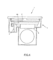
FIG. 4 is a schematic diagram illustrating a motor control unit according to a second embodiment. - A description will now be made for a motor control unit according to a first embodiment.
FIG. 1 is a schematic cross-sectional view illustrating the motor control unit. - The
motor control unit 1 includes amotor unit 2 having amotor 4 and aninverter unit 3. - The
inverter unit 3 includes apower module unit 5, asupport board 6, asmoothing capacitor 7, acontrol board 8, abusbar 9, afirst casing 10, afirst connector unit 14, and asecond connector unit 15. - The
power module unit 5 includes apower module 12 formed of a semiconductor device such as a transistor and installed in acooler 11 by interposing an insulator and asecond casing 13 that houses thepower module 12. A coolant such as air or a cooling water flows to thecooler 11 so that thepower module 12 is cooled by the coolant. - The
support board 6 is a plate-shaped board and is installed in the outer surface of thesecond casing 13. Thesmoothing capacitor 7, thecontrol board 8, thebusbar 9, and theboard mount portion 18 are installed in thesupport board 6. As thesupport board 6 is seen from themotor 4 side, thesmoothing capacitor 7 and thebusbar 9 are arranged in parallel, and thecontrol board 8 is arranged to intersect with thesmoothing capacitor 7 and thebusbar 9 as illustrated inFIG. 2 . That is, thesmoothing capacitor 7, thecontrol board 8, and thebusbar 9 are arranged on thesupport board 6 in an approximately U-shape as seen from themotor 4 side.FIG. 2 illustrates only thesupport board 6, thecontrol board 8, thebusbar 9, and thesmoothing capacitor 7. Thesupport board 6 is provided with a circuit for controlling thepower module 12 and the like. - The
power module 12, thesecond casing 13, and thesupport board 6 are stacked on thecooler 11, and themotor unit 2 is provided along this stacking direction. That is, thesupport board 6 and themotor 4 are arranged along the stacking direction, and the juxtaposing direction of thesupport board 6 and themotor 4 matches the stacking direction. - The
control board 8 is a plate-shaped board provided with a circuit for controlling themotor 4 and is fixed to theboard mount portion 18 erected on thesupport board 6. Specifically, thecontrol board 8 is arranged perpendicularly to thesupport board 6 in parallel with theboard mount portion 18. It is noted that thecontrol board 8 may be directly erected on thesupport board 6 without using theboard mount portion 18. - The
busbar 9 is used to connect themotor 4 and thepower module 12. - A description will now be made for the
first connector unit 14 with reference toFIG. 3. FIG. 3 is a schematic cross-sectional view taken along the line III-III ofFIG. 1 , in which a part of the elements are omitted intentionally for convenience purposes. - The
first connector unit 14 is connected to thecontrol board 8. Thefirst connector unit 14 extends from the connecting portion in a plane direction of thecontrol board 8, which intersects with a direction where thecontrol board 8 is installed in thesupport board 6, while it penetrates a through-hole 10a of thefirst casing 10, and a part thereof is positioned in the outside of thefirst casing 10. Specifically, thefirst connector unit 14 is provided to extend in a plane direction of thecontrol board 8 perpendicular to a direction where thecontrol board 8 is installed in thesupport board 6. In addition, thefirst connector unit 14 is connected to a power source that supplies power to thecontrol board 8. As a result, it is possible to supply power to thecontrol board 8 through thefirst connector unit 14 from the outside of thefirst casing 10. Between thefirst connector unit 14 and the through-hole 10a of thefirst casing 10, afirst resin portion 16 for damping vibration is provided so that thefirst connector unit 14 and thecontrol board 8 are supported by thefirst casing 10 by interposing thefirst resin portion 16. - The
first resin portion 16 is formed of a resin having an elastic damping characteristic in order to prevent vibration generated from themotor 4 and the like from being transmitted to thecontrol board 8 through thefirst casing 10 and thefirst connector unit 14. Thefirst resin portion 16 is fitted to asecond resin portion 17 that damps vibration in the outside of thefirst casing 10. - The
second resin portion 17 is formed of a resin having an elastic damping characteristic and is installed in thefirst casing 10 using a bolt, a nut, and the like. Thefirst connector unit 14 and thecontrol board 8 are supported by thefirst casing 10 by interposing thesecond resin portion 17. Thesecond resin portion 17 prevents vibration generated from themotor 4 or the like from being transmitted to thecontrol board 8 through thefirst casing 10 and thefirst connector unit 14. Thefirst connector unit 14 and thecontrol board 8 are supported by thefirst casing 10 by interposing thesecond resin portion 17. - The
second connector unit 15 is provided in an end portion of thecontrol board 8 opposite to the end portion supported by thesupport board 6 and is connected to thecontrol board 8, thesupport board 6, and the like. - In this embodiment, the
control board 8 is supported by theboard mount portion 18 erected on thesupport board 6 and is also supported by thefirst casing 10 by interposing the first andsecond resin portions control board 8 is supported from different directions. - A description will now be made for the effects of the first embodiment of the invention.
- If the control board is arranged in a stacking manner between the support board and the motor and the like, the length of the motor control unit increases in the stacking direction.
- In this embodiment, the
control board 8 of themotor control unit 1 is supported by theboard mount portion 18 erected on thesupport board 6. In the direction where thesupport board 6 and themotor 4 are arranged, it is necessary to provide a length matching with the size of themotor 4, and in this embodiment, a space corresponding to this length can be effectively used. For this reason, it is possible to shorten the length of themotor control unit 1 in the juxtaposing direction of thesupport board 6 and themotor 4, that is, in the stacking direction of thesupport board 6 and the like. Therefore, it is possible to miniaturize themotor control unit 1. - Since the
control board 8 is supported by thefirst casing 10 using thefirst connector unit 14 that supplies power to thecontrol board 8 from the outside, thecontrol board 8 is supported in two directions. Therefore, it is possible to improve a support rigidity of thecontrol board 8. - Since the
first resin portion 16 capable of damping vibration is provided between thefirst connector unit 14 and the through-hole 10a of thefirst casing 10, it is possible to prevent vibration generated from themotor 4 or the like from being transmitted to thecontrol board 8 through thefirst casing 10 and thefirst connector unit 14. - When the
motor control unit 1 is mounted on a vehicle, for example, vibration input from a road surface during a travel or vibration generated from an engine in the case of a hybrid vehicle is also transmitted in addition to the vibration generated from themotor 4. For this reason, it is preferable that the vibration transmitted to thecontrol board 8 be damped by increasing the support rigidity of thecontrol board 8. Since themotor control unit 1 of this embodiment can damp vibration by increasing the support rigidity of thecontrol board 8, it is possible to improve a vibration resistance of thecontrol board 8. - Since the
second connector unit 15 is provided in another end portion of thecontrol board 8 opposite to the end portion where thesupport board 6 is installed, it is possible to easily perform wiring for thecontrol board 8, thesupport board 6, and the like. - Next, a description will be made for a second embodiment of the invention with reference to
FIG. 4 . - The description will focus on differences between the first and second embodiments.
- In the
inverter unit 3 of themotor control unit 1 according this embodiment, thebusbar 9 and thecontrol board 8 are connected using thesupport portion 20. - The
support portion 20 is erected on thesupport board 6. Specifically, thesupport portion 20 is arranged perpendicularly to thesupport board 6 and is installed in thesupport board 6, for example, using a bolt and a nut. Thesupport portion 20 is arranged perpendicularly to thecontrol board 8 and is installed in the end portion of thecontrol board 8. As a result, thecontrol board 8 is supported by thesupport board 6 using thesupport portion 20. - The
support portion 20 is formed of a resin having an elastic damping characteristic. Thesupport portion 20 covers a surface of thebusbar 9 and is integrated into thesupport portion 20 and thebusbar 9. - A description will now be made for the effects of the second embodiment of the invention.
- Since the
control board 8 is supported by thesupport board 6 using thesupport portion 20, it is possible to increase a support rigidity of thecontrol board 8. In addition, since thesupport portion 20 is formed of a resin having an elastic damping characteristic, it is possible to prevent vibration generated from themotor 4 from being transmitted to thecontrol board 8 through thesupport portion 20. - Although the embodiments of the present invention have been described above, the above embodiments are only an illustration of some application examples of the present invention and not intended to limit the technical scope of the present invention to the specific configurations of the above embodiments.
- Although the first and
second resin portions - Although, in the aforementioned embodiment, the
first connector unit 14 is provided in a direction intersecting with a direction where thecontrol board 8 is installed in thesupport board 6, and thesecond connector unit 15 is provided in another end portion opposite to the end portion supported by thesupport board 6, the invention is not limited thereto. For example, the first and second connector units may be provided conversely. - The
support portion 20 according to the second embodiment may be installed in thecontrol board 8 in the vicinity of the center of thecontrol board 8. - This application claims a priority to Japanese Patent Application No.
2012-26013
Claims (7)
- A motor control unit obtained by integrating an inverter unit and a motor unit having a motor, the inverter unit comprising
a control board erected on a support board. - The motor control unit according to claim 1, wherein the inverter unit comprises a casing that houses the support board and
a power supply unit that penetrates the casing and connects a power source and the control board, and
the control board is supported by the casing using the power supply unit. - The motor control unit according to claim 1 or 2, wherein the inverter unit comprises a plate-shaped board mount portion erected on the support board, and the control board is installed in the board mount portion.
- The motor control unit according to any one of claims 1 to 3, wherein the inverter unit comprises a casing that houses the support board,
a power supply unit that penetrates the casing and connects a power source and the control board, and
a damping portion that damps vibration between the power supply unit and the casing. - The motor control unit according to any one of claims 1 to 4, wherein the control board is supported by a busbar.
- The motor control unit according to any one of claims 1 to 5, wherein the inverter unit comprsies a connector unit connected to another end portion of the control board different from an end portion supported by the support board.
- The motor control unit according to any one of claims 1 to 6, wherein the control board is erected along a juxtaposing direction of the support board and the motor.
Applications Claiming Priority (2)
| Application Number | Priority Date | Filing Date | Title |
|---|---|---|---|
| JP2012026013A JP5810953B2 (en) | 2012-02-09 | 2012-02-09 | Motor control unit |
| PCT/JP2013/052456 WO2013118674A1 (en) | 2012-02-09 | 2013-02-04 | Motor control unit |
Publications (3)
| Publication Number | Publication Date |
|---|---|
| EP2814145A1 true EP2814145A1 (en) | 2014-12-17 |
| EP2814145A4 EP2814145A4 (en) | 2016-07-20 |
| EP2814145B1 EP2814145B1 (en) | 2020-12-16 |
Family
ID=48947438
Family Applications (1)
| Application Number | Title | Priority Date | Filing Date |
|---|---|---|---|
| EP13747127.2A Active EP2814145B1 (en) | 2012-02-09 | 2013-02-04 | Motor control unit |
Country Status (5)
| Country | Link |
|---|---|
| US (1) | US9647514B2 (en) |
| EP (1) | EP2814145B1 (en) |
| JP (1) | JP5810953B2 (en) |
| CN (1) | CN104094505B (en) |
| WO (1) | WO2013118674A1 (en) |
Families Citing this family (5)
| Publication number | Priority date | Publication date | Assignee | Title |
|---|---|---|---|---|
| CN114503399B (en) | 2019-09-30 | 2024-06-04 | 日本电产株式会社 | Motor unit |
| US12113404B2 (en) | 2019-09-30 | 2024-10-08 | Nidec Corporation | Motor unit |
| JP7544065B2 (en) | 2019-09-30 | 2024-09-03 | ニデック株式会社 | Motor Unit |
| DE102021205054A1 (en) | 2021-05-18 | 2022-11-24 | Volkswagen Aktiengesellschaft | Motor housing with pressure device, electric machine and motor vehicle |
| US12377811B2 (en) | 2023-02-28 | 2025-08-05 | Honda Motor Co., Ltd. | Keyless dual power system control for electric motor vehicles |
Family Cites Families (11)
| Publication number | Priority date | Publication date | Assignee | Title |
|---|---|---|---|---|
| JP2002165412A (en) * | 2000-11-24 | 2002-06-07 | Mitsuba Corp | Electric motor unit |
| US6992409B2 (en) * | 2002-03-15 | 2006-01-31 | Denso Corporation | Liquid-cooled rotary electric machine integrated with an inverter |
| JP3760887B2 (en) * | 2002-04-26 | 2006-03-29 | 株式会社デンソー | Inverter integrated motor for vehicles |
| EP1363026A3 (en) * | 2002-04-26 | 2004-09-01 | Denso Corporation | Invertor integrated motor for an automotive vehicle |
| JP3934523B2 (en) * | 2002-10-08 | 2007-06-20 | アスモ株式会社 | motor |
| JP4243954B2 (en) | 2002-12-27 | 2009-03-25 | アイシン・エィ・ダブリュ株式会社 | Vibration control device for electric drive control unit |
| JP2007282309A (en) * | 2006-04-03 | 2007-10-25 | Denso Corp | Vehicle motor drive device |
| JP2009127523A (en) * | 2007-11-22 | 2009-06-11 | Mitsubishi Heavy Ind Ltd | Inverter-integrated electric compressor |
| JP2009132174A (en) * | 2007-11-28 | 2009-06-18 | Mitsubishi Electric Corp | Electric power steering device |
| JP5393324B2 (en) * | 2009-07-30 | 2014-01-22 | 三菱重工業株式会社 | Inverter-integrated electric compressor |
| JP2012026013A (en) | 2010-07-27 | 2012-02-09 | Kansai Coke & Chem Co Ltd | Component for film-forming apparatus and method for removing film adhered to the same |
-
2012
- 2012-02-09 JP JP2012026013A patent/JP5810953B2/en active Active
-
2013
- 2013-02-04 US US14/376,980 patent/US9647514B2/en active Active
- 2013-02-04 WO PCT/JP2013/052456 patent/WO2013118674A1/en not_active Ceased
- 2013-02-04 EP EP13747127.2A patent/EP2814145B1/en active Active
- 2013-02-04 CN CN201380007912.5A patent/CN104094505B/en active Active
Also Published As
| Publication number | Publication date |
|---|---|
| EP2814145B1 (en) | 2020-12-16 |
| WO2013118674A1 (en) | 2013-08-15 |
| CN104094505B (en) | 2016-10-12 |
| US20150008804A1 (en) | 2015-01-08 |
| EP2814145A4 (en) | 2016-07-20 |
| JP2013165538A (en) | 2013-08-22 |
| CN104094505A (en) | 2014-10-08 |
| JP5810953B2 (en) | 2015-11-11 |
| US9647514B2 (en) | 2017-05-09 |
Similar Documents
| Publication | Publication Date | Title |
|---|---|---|
| US8693193B2 (en) | Power converter | |
| US9647514B2 (en) | Motor control unit having integrated inverter unit | |
| US8988861B2 (en) | Power converter | |
| US9894812B2 (en) | Inverter case | |
| EP1657806B1 (en) | Power converter and semiconductor device mounting structure | |
| US10008895B2 (en) | Inverter-integrated electric compressor | |
| CN107405988B (en) | motor vehicle | |
| US8659194B2 (en) | Motor drive apparatus | |
| WO2017135071A1 (en) | Power conversion device | |
| US20140254103A1 (en) | Electronic control unit | |
| JP6838501B2 (en) | Electronic control device and electric power steering device using this | |
| US10348216B2 (en) | Electric power converting apparatus with inner plane of control board fixed to housing | |
| KR101610901B1 (en) | Electronic control apparatus for vehicle | |
| JPWO2014045700A1 (en) | Power converter mounted on electric vehicle | |
| JP5885773B2 (en) | Power converter | |
| JP7167609B2 (en) | electric pump device | |
| CN110073587A (en) | Capacitor unit, motor compressor | |
| JP2011114872A (en) | Power conversion apparatus | |
| US9931937B2 (en) | Vehicle installation structure | |
| US20190373718A1 (en) | Circuit board | |
| JP2020161547A (en) | Power converter | |
| JP7600838B2 (en) | Electronic Control Module | |
| JP2012199451A (en) | Electronic controller | |
| CN109671562B (en) | Noise reduction structure of bus capacitor, bus capacitor and electric automobile | |
| JP2024151749A (en) | Power conversion device and its manufacturing method |
Legal Events
| Date | Code | Title | Description |
|---|---|---|---|
| PUAI | Public reference made under article 153(3) epc to a published international application that has entered the european phase |
Free format text: ORIGINAL CODE: 0009012 |
|
| 17P | Request for examination filed |
Effective date: 20140730 |
|
| AK | Designated contracting states |
Kind code of ref document: A1 Designated state(s): AL AT BE BG CH CY CZ DE DK EE ES FI FR GB GR HR HU IE IS IT LI LT LU LV MC MK MT NL NO PL PT RO RS SE SI SK SM TR |
|
| AX | Request for extension of the european patent |
Extension state: BA ME |
|
| DAX | Request for extension of the european patent (deleted) | ||
| RA4 | Supplementary search report drawn up and despatched (corrected) |
Effective date: 20160621 |
|
| RIC1 | Information provided on ipc code assigned before grant |
Ipc: H02K 11/00 20160101AFI20160615BHEP |
|
| STAA | Information on the status of an ep patent application or granted ep patent |
Free format text: STATUS: EXAMINATION IS IN PROGRESS |
|
| 17Q | First examination report despatched |
Effective date: 20191104 |
|
| REG | Reference to a national code |
Ref country code: DE Ref legal event code: R079 Ref document number: 602013074737 Country of ref document: DE Free format text: PREVIOUS MAIN CLASS: H02K0011000000 Ipc: H02K0011330000 |
|
| RIC1 | Information provided on ipc code assigned before grant |
Ipc: H02K 5/24 20060101ALI20200820BHEP Ipc: H02K 5/22 20060101ALI20200820BHEP Ipc: H02K 11/33 20160101AFI20200820BHEP |
|
| GRAP | Despatch of communication of intention to grant a patent |
Free format text: ORIGINAL CODE: EPIDOSNIGR1 |
|
| STAA | Information on the status of an ep patent application or granted ep patent |
Free format text: STATUS: GRANT OF PATENT IS INTENDED |
|
| INTG | Intention to grant announced |
Effective date: 20201007 |
|
| GRAS | Grant fee paid |
Free format text: ORIGINAL CODE: EPIDOSNIGR3 |
|
| GRAA | (expected) grant |
Free format text: ORIGINAL CODE: 0009210 |
|
| STAA | Information on the status of an ep patent application or granted ep patent |
Free format text: STATUS: THE PATENT HAS BEEN GRANTED |
|
| AK | Designated contracting states |
Kind code of ref document: B1 Designated state(s): AL AT BE BG CH CY CZ DE DK EE ES FI FR GB GR HR HU IE IS IT LI LT LU LV MC MK MT NL NO PL PT RO RS SE SI SK SM TR |
|
| RAP1 | Party data changed (applicant data changed or rights of an application transferred) |
Owner name: NISSAN MOTOR CO., LTD. |
|
| REG | Reference to a national code |
Ref country code: GB Ref legal event code: FG4D |
|
| RIN1 | Information on inventor provided before grant (corrected) |
Inventor name: KATAKAMI, AKIHIRO Inventor name: KAWAMURA, TOMOKI Inventor name: SHIMIZU, HIROFUMI Inventor name: TAKAHASHI, HIROAKI |
|
| REG | Reference to a national code |
Ref country code: DE Ref legal event code: R096 Ref document number: 602013074737 Country of ref document: DE |
|
| REG | Reference to a national code |
Ref country code: IE Ref legal event code: FG4D |
|
| REG | Reference to a national code |
Ref country code: AT Ref legal event code: REF Ref document number: 1346494 Country of ref document: AT Kind code of ref document: T Effective date: 20210115 |
|
| PG25 | Lapsed in a contracting state [announced via postgrant information from national office to epo] |
Ref country code: GR Free format text: LAPSE BECAUSE OF FAILURE TO SUBMIT A TRANSLATION OF THE DESCRIPTION OR TO PAY THE FEE WITHIN THE PRESCRIBED TIME-LIMIT Effective date: 20210317 Ref country code: RS Free format text: LAPSE BECAUSE OF FAILURE TO SUBMIT A TRANSLATION OF THE DESCRIPTION OR TO PAY THE FEE WITHIN THE PRESCRIBED TIME-LIMIT Effective date: 20201216 Ref country code: FI Free format text: LAPSE BECAUSE OF FAILURE TO SUBMIT A TRANSLATION OF THE DESCRIPTION OR TO PAY THE FEE WITHIN THE PRESCRIBED TIME-LIMIT Effective date: 20201216 Ref country code: NO Free format text: LAPSE BECAUSE OF FAILURE TO SUBMIT A TRANSLATION OF THE DESCRIPTION OR TO PAY THE FEE WITHIN THE PRESCRIBED TIME-LIMIT Effective date: 20210316 |
|
| REG | Reference to a national code |
Ref country code: AT Ref legal event code: MK05 Ref document number: 1346494 Country of ref document: AT Kind code of ref document: T Effective date: 20201216 |
|
| REG | Reference to a national code |
Ref country code: NL Ref legal event code: MP Effective date: 20201216 |
|
| PG25 | Lapsed in a contracting state [announced via postgrant information from national office to epo] |
Ref country code: LV Free format text: LAPSE BECAUSE OF FAILURE TO SUBMIT A TRANSLATION OF THE DESCRIPTION OR TO PAY THE FEE WITHIN THE PRESCRIBED TIME-LIMIT Effective date: 20201216 Ref country code: SE Free format text: LAPSE BECAUSE OF FAILURE TO SUBMIT A TRANSLATION OF THE DESCRIPTION OR TO PAY THE FEE WITHIN THE PRESCRIBED TIME-LIMIT Effective date: 20201216 Ref country code: BG Free format text: LAPSE BECAUSE OF FAILURE TO SUBMIT A TRANSLATION OF THE DESCRIPTION OR TO PAY THE FEE WITHIN THE PRESCRIBED TIME-LIMIT Effective date: 20210316 |
|
| PG25 | Lapsed in a contracting state [announced via postgrant information from national office to epo] |
Ref country code: HR Free format text: LAPSE BECAUSE OF FAILURE TO SUBMIT A TRANSLATION OF THE DESCRIPTION OR TO PAY THE FEE WITHIN THE PRESCRIBED TIME-LIMIT Effective date: 20201216 Ref country code: NL Free format text: LAPSE BECAUSE OF FAILURE TO SUBMIT A TRANSLATION OF THE DESCRIPTION OR TO PAY THE FEE WITHIN THE PRESCRIBED TIME-LIMIT Effective date: 20201216 |
|
| REG | Reference to a national code |
Ref country code: LT Ref legal event code: MG9D |
|
| PG25 | Lapsed in a contracting state [announced via postgrant information from national office to epo] |
Ref country code: LT Free format text: LAPSE BECAUSE OF FAILURE TO SUBMIT A TRANSLATION OF THE DESCRIPTION OR TO PAY THE FEE WITHIN THE PRESCRIBED TIME-LIMIT Effective date: 20201216 Ref country code: RO Free format text: LAPSE BECAUSE OF FAILURE TO SUBMIT A TRANSLATION OF THE DESCRIPTION OR TO PAY THE FEE WITHIN THE PRESCRIBED TIME-LIMIT Effective date: 20201216 Ref country code: SK Free format text: LAPSE BECAUSE OF FAILURE TO SUBMIT A TRANSLATION OF THE DESCRIPTION OR TO PAY THE FEE WITHIN THE PRESCRIBED TIME-LIMIT Effective date: 20201216 Ref country code: PT Free format text: LAPSE BECAUSE OF FAILURE TO SUBMIT A TRANSLATION OF THE DESCRIPTION OR TO PAY THE FEE WITHIN THE PRESCRIBED TIME-LIMIT Effective date: 20210416 Ref country code: SM Free format text: LAPSE BECAUSE OF FAILURE TO SUBMIT A TRANSLATION OF THE DESCRIPTION OR TO PAY THE FEE WITHIN THE PRESCRIBED TIME-LIMIT Effective date: 20201216 Ref country code: EE Free format text: LAPSE BECAUSE OF FAILURE TO SUBMIT A TRANSLATION OF THE DESCRIPTION OR TO PAY THE FEE WITHIN THE PRESCRIBED TIME-LIMIT Effective date: 20201216 Ref country code: CZ Free format text: LAPSE BECAUSE OF FAILURE TO SUBMIT A TRANSLATION OF THE DESCRIPTION OR TO PAY THE FEE WITHIN THE PRESCRIBED TIME-LIMIT Effective date: 20201216 |
|
| PG25 | Lapsed in a contracting state [announced via postgrant information from national office to epo] |
Ref country code: PL Free format text: LAPSE BECAUSE OF FAILURE TO SUBMIT A TRANSLATION OF THE DESCRIPTION OR TO PAY THE FEE WITHIN THE PRESCRIBED TIME-LIMIT Effective date: 20201216 Ref country code: AT Free format text: LAPSE BECAUSE OF FAILURE TO SUBMIT A TRANSLATION OF THE DESCRIPTION OR TO PAY THE FEE WITHIN THE PRESCRIBED TIME-LIMIT Effective date: 20201216 |
|
| REG | Reference to a national code |
Ref country code: DE Ref legal event code: R097 Ref document number: 602013074737 Country of ref document: DE |
|
| PG25 | Lapsed in a contracting state [announced via postgrant information from national office to epo] |
Ref country code: MC Free format text: LAPSE BECAUSE OF FAILURE TO SUBMIT A TRANSLATION OF THE DESCRIPTION OR TO PAY THE FEE WITHIN THE PRESCRIBED TIME-LIMIT Effective date: 20201216 Ref country code: IS Free format text: LAPSE BECAUSE OF FAILURE TO SUBMIT A TRANSLATION OF THE DESCRIPTION OR TO PAY THE FEE WITHIN THE PRESCRIBED TIME-LIMIT Effective date: 20210416 |
|
| PLBE | No opposition filed within time limit |
Free format text: ORIGINAL CODE: 0009261 |
|
| STAA | Information on the status of an ep patent application or granted ep patent |
Free format text: STATUS: NO OPPOSITION FILED WITHIN TIME LIMIT |
|
| REG | Reference to a national code |
Ref country code: BE Ref legal event code: MM Effective date: 20210228 |
|
| PG25 | Lapsed in a contracting state [announced via postgrant information from national office to epo] |
Ref country code: LI Free format text: LAPSE BECAUSE OF NON-PAYMENT OF DUE FEES Effective date: 20210228 Ref country code: LU Free format text: LAPSE BECAUSE OF NON-PAYMENT OF DUE FEES Effective date: 20210204 Ref country code: IT Free format text: LAPSE BECAUSE OF FAILURE TO SUBMIT A TRANSLATION OF THE DESCRIPTION OR TO PAY THE FEE WITHIN THE PRESCRIBED TIME-LIMIT Effective date: 20201216 Ref country code: CH Free format text: LAPSE BECAUSE OF NON-PAYMENT OF DUE FEES Effective date: 20210228 Ref country code: AL Free format text: LAPSE BECAUSE OF FAILURE TO SUBMIT A TRANSLATION OF THE DESCRIPTION OR TO PAY THE FEE WITHIN THE PRESCRIBED TIME-LIMIT Effective date: 20201216 |
|
| 26N | No opposition filed |
Effective date: 20210917 |
|
| PG25 | Lapsed in a contracting state [announced via postgrant information from national office to epo] |
Ref country code: DK Free format text: LAPSE BECAUSE OF FAILURE TO SUBMIT A TRANSLATION OF THE DESCRIPTION OR TO PAY THE FEE WITHIN THE PRESCRIBED TIME-LIMIT Effective date: 20201216 Ref country code: ES Free format text: LAPSE BECAUSE OF FAILURE TO SUBMIT A TRANSLATION OF THE DESCRIPTION OR TO PAY THE FEE WITHIN THE PRESCRIBED TIME-LIMIT Effective date: 20201216 |
|
| PG25 | Lapsed in a contracting state [announced via postgrant information from national office to epo] |
Ref country code: IE Free format text: LAPSE BECAUSE OF NON-PAYMENT OF DUE FEES Effective date: 20210204 |
|
| PG25 | Lapsed in a contracting state [announced via postgrant information from national office to epo] |
Ref country code: SI Free format text: LAPSE BECAUSE OF FAILURE TO SUBMIT A TRANSLATION OF THE DESCRIPTION OR TO PAY THE FEE WITHIN THE PRESCRIBED TIME-LIMIT Effective date: 20201216 |
|
| PG25 | Lapsed in a contracting state [announced via postgrant information from national office to epo] |
Ref country code: IS Free format text: LAPSE BECAUSE OF FAILURE TO SUBMIT A TRANSLATION OF THE DESCRIPTION OR TO PAY THE FEE WITHIN THE PRESCRIBED TIME-LIMIT Effective date: 20210416 |
|
| PG25 | Lapsed in a contracting state [announced via postgrant information from national office to epo] |
Ref country code: BE Free format text: LAPSE BECAUSE OF NON-PAYMENT OF DUE FEES Effective date: 20210228 |
|
| PG25 | Lapsed in a contracting state [announced via postgrant information from national office to epo] |
Ref country code: HU Free format text: LAPSE BECAUSE OF FAILURE TO SUBMIT A TRANSLATION OF THE DESCRIPTION OR TO PAY THE FEE WITHIN THE PRESCRIBED TIME-LIMIT; INVALID AB INITIO Effective date: 20130204 |
|
| PG25 | Lapsed in a contracting state [announced via postgrant information from national office to epo] |
Ref country code: CY Free format text: LAPSE BECAUSE OF FAILURE TO SUBMIT A TRANSLATION OF THE DESCRIPTION OR TO PAY THE FEE WITHIN THE PRESCRIBED TIME-LIMIT Effective date: 20201216 |
|
| PG25 | Lapsed in a contracting state [announced via postgrant information from national office to epo] |
Ref country code: MK Free format text: LAPSE BECAUSE OF FAILURE TO SUBMIT A TRANSLATION OF THE DESCRIPTION OR TO PAY THE FEE WITHIN THE PRESCRIBED TIME-LIMIT Effective date: 20201216 |
|
| PG25 | Lapsed in a contracting state [announced via postgrant information from national office to epo] |
Ref country code: MT Free format text: LAPSE BECAUSE OF FAILURE TO SUBMIT A TRANSLATION OF THE DESCRIPTION OR TO PAY THE FEE WITHIN THE PRESCRIBED TIME-LIMIT Effective date: 20201216 |
|
| PG25 | Lapsed in a contracting state [announced via postgrant information from national office to epo] |
Ref country code: TR Free format text: LAPSE BECAUSE OF FAILURE TO SUBMIT A TRANSLATION OF THE DESCRIPTION OR TO PAY THE FEE WITHIN THE PRESCRIBED TIME-LIMIT Effective date: 20201216 |
|
| PGFP | Annual fee paid to national office [announced via postgrant information from national office to epo] |
Ref country code: GB Payment date: 20260121 Year of fee payment: 14 |
|
| PGFP | Annual fee paid to national office [announced via postgrant information from national office to epo] |
Ref country code: DE Payment date: 20260121 Year of fee payment: 14 |
|
| PGFP | Annual fee paid to national office [announced via postgrant information from national office to epo] |
Ref country code: FR Payment date: 20260121 Year of fee payment: 14 |