EP2814092A1 - Secondary battery and electrode for secondary battery - Google Patents
Secondary battery and electrode for secondary battery Download PDFInfo
- Publication number
- EP2814092A1 EP2814092A1 EP13003235.2A EP13003235A EP2814092A1 EP 2814092 A1 EP2814092 A1 EP 2814092A1 EP 13003235 A EP13003235 A EP 13003235A EP 2814092 A1 EP2814092 A1 EP 2814092A1
- Authority
- EP
- European Patent Office
- Prior art keywords
- electrode
- particles
- secondary battery
- battery
- transmission member
- Prior art date
- Legal status (The legal status is an assumption and is not a legal conclusion. Google has not performed a legal analysis and makes no representation as to the accuracy of the status listed.)
- Withdrawn
Links
Images


Classifications
-
- H—ELECTRICITY
- H01—ELECTRIC ELEMENTS
- H01M—PROCESSES OR MEANS, e.g. BATTERIES, FOR THE DIRECT CONVERSION OF CHEMICAL ENERGY INTO ELECTRICAL ENERGY
- H01M10/00—Secondary cells; Manufacture thereof
- H01M10/36—Accumulators not provided for in groups H01M10/05-H01M10/34
- H01M10/38—Construction or manufacture
-
- H—ELECTRICITY
- H01—ELECTRIC ELEMENTS
- H01M—PROCESSES OR MEANS, e.g. BATTERIES, FOR THE DIRECT CONVERSION OF CHEMICAL ENERGY INTO ELECTRICAL ENERGY
- H01M4/00—Electrodes
- H01M4/02—Electrodes composed of, or comprising, active material
- H01M4/13—Electrodes for accumulators with non-aqueous electrolyte, e.g. for lithium-accumulators; Processes of manufacture thereof
- H01M4/131—Electrodes based on mixed oxides or hydroxides, or on mixtures of oxides or hydroxides, e.g. LiCoOx
-
- H—ELECTRICITY
- H01—ELECTRIC ELEMENTS
- H01M—PROCESSES OR MEANS, e.g. BATTERIES, FOR THE DIRECT CONVERSION OF CHEMICAL ENERGY INTO ELECTRICAL ENERGY
- H01M4/00—Electrodes
- H01M4/02—Electrodes composed of, or comprising, active material
- H01M4/13—Electrodes for accumulators with non-aqueous electrolyte, e.g. for lithium-accumulators; Processes of manufacture thereof
- H01M4/133—Electrodes based on carbonaceous material, e.g. graphite-intercalation compounds or CFx
-
- H—ELECTRICITY
- H01—ELECTRIC ELEMENTS
- H01M—PROCESSES OR MEANS, e.g. BATTERIES, FOR THE DIRECT CONVERSION OF CHEMICAL ENERGY INTO ELECTRICAL ENERGY
- H01M4/00—Electrodes
- H01M4/02—Electrodes composed of, or comprising, active material
- H01M4/13—Electrodes for accumulators with non-aqueous electrolyte, e.g. for lithium-accumulators; Processes of manufacture thereof
- H01M4/134—Electrodes based on metals, Si or alloys
-
- H—ELECTRICITY
- H01—ELECTRIC ELEMENTS
- H01M—PROCESSES OR MEANS, e.g. BATTERIES, FOR THE DIRECT CONVERSION OF CHEMICAL ENERGY INTO ELECTRICAL ENERGY
- H01M4/00—Electrodes
- H01M4/02—Electrodes composed of, or comprising, active material
- H01M4/36—Selection of substances as active materials, active masses, active liquids
- H01M4/362—Composites
- H01M4/364—Composites as mixtures
-
- H—ELECTRICITY
- H01—ELECTRIC ELEMENTS
- H01M—PROCESSES OR MEANS, e.g. BATTERIES, FOR THE DIRECT CONVERSION OF CHEMICAL ENERGY INTO ELECTRICAL ENERGY
- H01M10/00—Secondary cells; Manufacture thereof
- H01M10/05—Accumulators with non-aqueous electrolyte
- H01M10/052—Li-accumulators
- H01M10/0525—Rocking-chair batteries, i.e. batteries with lithium insertion or intercalation in both electrodes; Lithium-ion batteries
-
- H—ELECTRICITY
- H01—ELECTRIC ELEMENTS
- H01M—PROCESSES OR MEANS, e.g. BATTERIES, FOR THE DIRECT CONVERSION OF CHEMICAL ENERGY INTO ELECTRICAL ENERGY
- H01M4/00—Electrodes
- H01M4/02—Electrodes composed of, or comprising, active material
- H01M4/13—Electrodes for accumulators with non-aqueous electrolyte, e.g. for lithium-accumulators; Processes of manufacture thereof
- H01M4/139—Processes of manufacture
- H01M4/1391—Processes of manufacture of electrodes based on mixed oxides or hydroxides, or on mixtures of oxides or hydroxides, e.g. LiCoOx
-
- H—ELECTRICITY
- H01—ELECTRIC ELEMENTS
- H01M—PROCESSES OR MEANS, e.g. BATTERIES, FOR THE DIRECT CONVERSION OF CHEMICAL ENERGY INTO ELECTRICAL ENERGY
- H01M4/00—Electrodes
- H01M4/02—Electrodes composed of, or comprising, active material
- H01M4/13—Electrodes for accumulators with non-aqueous electrolyte, e.g. for lithium-accumulators; Processes of manufacture thereof
- H01M4/139—Processes of manufacture
- H01M4/1393—Processes of manufacture of electrodes based on carbonaceous material, e.g. graphite-intercalation compounds or CFx
-
- H—ELECTRICITY
- H01—ELECTRIC ELEMENTS
- H01M—PROCESSES OR MEANS, e.g. BATTERIES, FOR THE DIRECT CONVERSION OF CHEMICAL ENERGY INTO ELECTRICAL ENERGY
- H01M4/00—Electrodes
- H01M4/02—Electrodes composed of, or comprising, active material
- H01M4/13—Electrodes for accumulators with non-aqueous electrolyte, e.g. for lithium-accumulators; Processes of manufacture thereof
- H01M4/139—Processes of manufacture
- H01M4/1395—Processes of manufacture of electrodes based on metals, Si or alloys
-
- H—ELECTRICITY
- H01—ELECTRIC ELEMENTS
- H01M—PROCESSES OR MEANS, e.g. BATTERIES, FOR THE DIRECT CONVERSION OF CHEMICAL ENERGY INTO ELECTRICAL ENERGY
- H01M4/00—Electrodes
- H01M4/02—Electrodes composed of, or comprising, active material
- H01M4/36—Selection of substances as active materials, active masses, active liquids
- H01M4/362—Composites
- H01M4/366—Composites as layered products
-
- H—ELECTRICITY
- H01—ELECTRIC ELEMENTS
- H01M—PROCESSES OR MEANS, e.g. BATTERIES, FOR THE DIRECT CONVERSION OF CHEMICAL ENERGY INTO ELECTRICAL ENERGY
- H01M4/00—Electrodes
- H01M4/02—Electrodes composed of, or comprising, active material
- H01M4/36—Selection of substances as active materials, active masses, active liquids
- H01M4/38—Selection of substances as active materials, active masses, active liquids of elements or alloys
- H01M4/381—Alkaline or alkaline earth metals elements
- H01M4/382—Lithium
-
- H—ELECTRICITY
- H01—ELECTRIC ELEMENTS
- H01M—PROCESSES OR MEANS, e.g. BATTERIES, FOR THE DIRECT CONVERSION OF CHEMICAL ENERGY INTO ELECTRICAL ENERGY
- H01M4/00—Electrodes
- H01M4/02—Electrodes composed of, or comprising, active material
- H01M4/36—Selection of substances as active materials, active masses, active liquids
- H01M4/48—Selection of substances as active materials, active masses, active liquids of inorganic oxides or hydroxides
- H01M4/485—Selection of substances as active materials, active masses, active liquids of inorganic oxides or hydroxides of mixed oxides or hydroxides for inserting or intercalating light metals, e.g. LiTi2O4 or LiTi2OxFy
-
- H—ELECTRICITY
- H01—ELECTRIC ELEMENTS
- H01M—PROCESSES OR MEANS, e.g. BATTERIES, FOR THE DIRECT CONVERSION OF CHEMICAL ENERGY INTO ELECTRICAL ENERGY
- H01M4/00—Electrodes
- H01M4/02—Electrodes composed of, or comprising, active material
- H01M4/36—Selection of substances as active materials, active masses, active liquids
- H01M4/58—Selection of substances as active materials, active masses, active liquids of inorganic compounds other than oxides or hydroxides, e.g. sulfides, selenides, tellurides, halogenides or LiCoFy; of polyanionic structures, e.g. phosphates, silicates or borates
- H01M4/583—Carbonaceous material, e.g. graphite-intercalation compounds or CFx
- H01M4/587—Carbonaceous material, e.g. graphite-intercalation compounds or CFx for inserting or intercalating light metals
-
- Y—GENERAL TAGGING OF NEW TECHNOLOGICAL DEVELOPMENTS; GENERAL TAGGING OF CROSS-SECTIONAL TECHNOLOGIES SPANNING OVER SEVERAL SECTIONS OF THE IPC; TECHNICAL SUBJECTS COVERED BY FORMER USPC CROSS-REFERENCE ART COLLECTIONS [XRACs] AND DIGESTS
- Y02—TECHNOLOGIES OR APPLICATIONS FOR MITIGATION OR ADAPTATION AGAINST CLIMATE CHANGE
- Y02E—REDUCTION OF GREENHOUSE GAS [GHG] EMISSIONS, RELATED TO ENERGY GENERATION, TRANSMISSION OR DISTRIBUTION
- Y02E60/00—Enabling technologies; Technologies with a potential or indirect contribution to GHG emissions mitigation
- Y02E60/10—Energy storage using batteries
-
- Y—GENERAL TAGGING OF NEW TECHNOLOGICAL DEVELOPMENTS; GENERAL TAGGING OF CROSS-SECTIONAL TECHNOLOGIES SPANNING OVER SEVERAL SECTIONS OF THE IPC; TECHNICAL SUBJECTS COVERED BY FORMER USPC CROSS-REFERENCE ART COLLECTIONS [XRACs] AND DIGESTS
- Y02—TECHNOLOGIES OR APPLICATIONS FOR MITIGATION OR ADAPTATION AGAINST CLIMATE CHANGE
- Y02P—CLIMATE CHANGE MITIGATION TECHNOLOGIES IN THE PRODUCTION OR PROCESSING OF GOODS
- Y02P70/00—Climate change mitigation technologies in the production process for final industrial or consumer products
- Y02P70/50—Manufacturing or production processes characterised by the final manufactured product
Definitions
- the ion transmission member is maintained in a state of any of liquid, gel, and solid.
- the transmitted ions may be lithium ions (Li + ), for example.
- the transmitted ions are preferably at least one of alkali metal ions and alkali earth metal ions.
- the electrode 10 preferably contains a compound containing alkali metal or alkali earth metal.
- the electrode 20 is preferably capable of occluding and extracting the alkali metal ions or the alkali earth metal ions.
- the electrode 10 may contain LiNi(Sb)O 2 , Li 2 MnO 3 , and LiMnPO 4 , for example.
- the core particles of the electrode 10 might be made of any one of LiNi(Sb)O 2 , Li 2 MnO 3 , and LiMnPO 4 .
- the nano particles of the electrode 10 might be made of mainly a eutectic substance of LiNi(Sb)O 2 and Li 2 MnO 3 .
- a polypropylene microporous film (separator) with a thickness of 20 ⁇ m was interposed between the positive and negative electrodes obtained as above to form a layered structure. Then, the layered structure was cut out into a predetermined size and was inserted in a battery can. Electrolyte was manufactured by dissolving 1 M of LiPF 6 into a mixed solvent obtained by mixing ethylene carbonate (EC), dimethyl carbonate (DMC), and methyl ethyl carbonate (MEC).
- EC ethylene carbonate
- DMC dimethyl carbonate
- MEC methyl ethyl carbonate
Abstract
Description
- The present invention relates to secondary batteries and electrodes for such a secondary battery.
- Batteries convert chemical energy of chemical substances provided in their interior to electric energy by an electrochemical oxidation-reduction reaction. Recently, the batteries are used worldwide mainly for portable electronic equipment in the fields of electronics, communications, computers, etc. Further, there is a future demand for practical use of batteries as large-scale devices for mobile entities (e.g., electric automobile, etc.) and stationary systems (e.g., a load-leveling system, etc.). Accordingly, the batteries are becoming more and more important key devices.
- Among the batteries, a lithium ion secondary battery is widely used at the present day. A general lithium ion secondary battery includes a positive electrode using a lithium transition metal composite oxide as an active material, a negative electrode using a material capable of occluding and extracting lithium ions (e.g., lithium metal, lithium alloy, metal oxide, or carbon) as an active material, nonaqueous electrolyte, and a separator (see, for example, Japanese Patent Application Laid-Open Publication No.
H05-242911 - However, the conventional lithium ion secondary battery is limited in output and capacity per unit weight. Accordingly, a novel secondary battery is demanded.
- The present invention has been made in view of the foregoing and has its object of providing a novel secondary battery which can attain high output or high capacity and an electrode for such a secondary battery.
- A secondary battery according to the present invention includes a positive electrode and a negative electrode. The negative electrode includes first particles made of metal and second particles made of a silicon containing substance. The first particles are in contact with the second particles.
- In one embodiment, the metal forming the first particles is ionized to move to the positive electrode in charge or discharge.
- In one embodiment, the metal forming the first particles functions as a donor. In one embodiment, the first particles are made of lithium.
- In one embodiment, the second particles are made of silicon oxide.
- In one embodiment, the negative electrode further includes a layered material, and the first particles and the second particles are located among layers of the layered material.
- In one embodiment, the layered material is made of graphene.
- In one embodiment, the layered material has an interlayer distance of 10 nm to 500 nm.
- In one embodiment, the positive electrode includes: core particles with a diameter of 1 µm or larger; and particles with a diameter of smaller than 1 µm formed on surfaces of the core particles.
- In one embodiment, the secondary battery includes: an ion transmission member configured to transmit ions between the negative electrode and the positive electrode; and a hole transmission member configured to transmit holes (positive holes) between the negative electrode and the positive electrode.
- In one embodiment, the ion transmission member is maintained in a state of any of liquid, gel, and solid.
- In one embodiment, the hole transmission member is composed of nonwoven cloth carrying a ceramic material.
- An electrode for a secondary battery according to the present invention includes: first particles made of metal; and second particles made of a silicon containing substance. The first particles are in contact with the second particles.
- According to the present invention, a secondary battery and an electrode for such a secondary battery can be provided which can attain high output and high capacity.
-
-
FIG. 1 is a schematic illustration of a secondary battery according to one embodiment of the present invention. -
FIG. 2 is a graph representation showing specific energy of a hybrid battery and a lithium ion battery. -
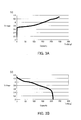
FIG. 3A is a graph representation showing charge characteristics of a lithium battery employing a positive electrode in which nano particles are formed on the surfaces of core particles. -
FIG. 3B is a graph representation showing discharge characteristics of the lithium battery employing the positive electrode in which the nano particles are formed on the surfaces of the core particles. -
FIG. 4A is a first SEM photograph showing a structure of a positive electrode in Example 1. -
FIG. 4B is a second SEM photograph showing a structure of the positive electrode in Example 1. -
FIG. 4C is a third SEM photograph showing a structure of the positive electrode in Example 1. -
FIG. 5A is a first illustration schematically showing a structure in cross section of a negative electrode in Example 1, which was observed by EEELS and TEM. -
FIG. 5B is a second illustration schematically showing a structure in cross section of the negative electrode in Example 1, which was observed by EEELS and TEM. -
FIG. 6 is a table indicting results of an initial capacity evaluation, a nail penetration test, an overcharge test, and an evaluation of life characteristics at normal temperature in Example 1 and Comparative Examples 1 and 2. - Conventional lithium ion secondary batteries are limited in output and capacity per unit weight. Accordingly, a novel secondary battery is demanded. According to a secondary battery and an electrode for such a secondary battery, high output and high capacity can be attained.
- Embodiments of the present invention will be described below with reference to the accompanying drawings.
-
FIG. 1 is a schematic illustration of abattery 100 according to the present embodiment. - The
battery 100 in the present embodiment is a secondary battery. Thebattery 100 can convert electric energy obtained from an external power source to chemical energy, store the chemical energy, and take out the stored energy again as electromotive force according to need. - As shown in
FIG. 1 , thebattery 100 includeselectrodes ion transmission member 30, ahole transmission member 40, andcurrent collectors - The
electrode 10 serves as a positive electrode, while theelectrode 20 serves as a negative electrode in the present embodiment. Theion transmission member 30 transmits ions between theelectrode 10 and theelectrode 20. Thehole transmission member 40 transmits holes (positive holes) between theelectrode 10 and theelectrode 20. -
Vias 30a are formed in thehole transmission member 40 to extend in a direction orthogonal to the obverse and reverse surfaces of thehole transmission member 40. In the present embodiment, thehole transmission member 40 is immersed in electrolyte to fill thevias 30a with the electrolyte. Theion transmission member 30 is formed of the electrolyte in thevias 30a, for example. However, theion transmission member 30 is not limited to this and may be solid or gel. - The
electrode 10 faces theelectrode 20 with theion transmission member 30 and thehole transmission member 40 interposed. Each of theion transmission member 30 and thehole transmission member 40 is in contact with both theelectrode 10 and theelectrode 20. Theelectrode 10 is physically out of contact with theelectrode 20. Further, theelectrode 10 is in contact with thecurrent collector 110, while theelectrode 20 is in contact with thecurrent collector 120. - When the
electrode 10 is electrically connected to a high potential terminal of an external power source (not shown), and theelectrode 20 is electrically connected to a low potential terminal of the external power source (not shown), thebattery 100 is charged. In so doing, ions generated in theelectrode 10 move to theelectrode 20 through theion transmission member 30 to be occluded in theelectrode 20. Thus, the potential of theelectrode 10 becomes higher than that of theelectrode 20. - During discharge, electricity (electrical charge) flows from the
electrode 10 to theelectrode 20 through an external load (not shown). In so doing, ions (e.g., cations) generated in theelectrode 20 move to theelectrode 10 through theion transmission member 3 0. - Hereinafter, the ions transmitted through the
ion transmission member 30 are referred to as transmitted ions. - The transmitted ions may be lithium ions (Li+), for example. The transmitted ions are preferably at least one of alkali metal ions and alkali earth metal ions. The
electrode 10 preferably contains a compound containing alkali metal or alkali earth metal. Theelectrode 20 is preferably capable of occluding and extracting the alkali metal ions or the alkali earth metal ions. - The
electrode 10 is made of a p-type semiconductor, for example. Holes function as a carrier (charge carrier) in a p-type semiconductor. The holes move through theelectrode 10 in both charge and discharge. - The holes in the
electrode 10 move to theelectrode 20 through thehole transmission member 40 in charge. While on the other hand, theelectrode 10 receives the holes from an external power source (not shown). - The holes in the
electrode 10 move to theelectrode 20 through an external load (not shown) in discharge. While on the other hand, theelectrode 10 receives the holes through thehole transmission member 40. - Not only the ions but also the holes move in charge and discharge in the
battery 100 of the present embodiment. Specifically, in discharge, the ions generated in theelectrode 20 move to theelectrode 10 through theion transmission member 30. As well, due to the potential difference between theelectrode 10 and theelectrode 20, the holes are caused to circulate among theelectrode 10, an external load (not shown), theelectrode 20, and thehole transmission member 40 in this order. Further, in charge, the ions generated in theelectrode 10 move to theelectrode 20 through theion transmission member 30. As well, the holes are caused to circulate among theelectrode 10, thehole transmission member 40, theelectrode 20, and the external power source (not shown) in this order. - As described above, in the
battery 100 according to the present embodiment, the ions generated in theelectrode 10 or theelectrode 20 move between theelectrode 10 and theelectrode 20 through theion transmission member 30. Movement of the ions between theelectrode 10 and theelectrode 20 can attain high capacity of thebattery 100. Further, in thebattery 100 of the present embodiment, the holes move between theelectrode 10 and theelectrode 20 through thehole transmission member 40. The holes are smaller than the ions and have high mobility. Accordingly, thebattery 100 can attain high output. - As described above, the
battery 100 according to the present embodiment can attain high capacity and high output. Thebattery 100 in the present embodiment performs ion transmission through theion transmission member 30 and hole transmission through thehole transmission member 40. Thebattery 100 in the present embodiment is a hybrid battery that can exhibit both characteristics of a chemical battery (e.g., lithium battery) and a physical battery (e.g., semiconductor battery). -
FIG. 2 is a graph representation showing specific energy of the battery 100 (hybrid battery) according to the present embodiment and a general lithium ion battery. As understood fromFIG. 2 , the battery 100 (hybrid battery) according to the present embodiment can significantly improve output characteristics. - The amount of electrolyte as the
ion transmission member 30 can be reduced in thebattery 100 according to the present embodiment. Accordingly, even if theelectrode 10 would come into contact with theelectrode 20 to cause an internal short-circuit, an increase in temperature of thebattery 100 can be suppressed. Further, thebattery 100 of the present embodiment can decrease less in capacity at quick discharge and is excellent in cycle characteristic. - Where a n-type semiconductor is used as the
electrode 20 in addition to the use of the p-type semiconductor as theelectrode 10, the capacity and the output characteristics of thebattery 100 can be further improved. Whether theelectrode 10 and theelectrode 20 are a p-type semiconductor or a n-type semiconductor can be determined by measuring the Hall effect. When a magnetic field is applied, while electric current is allowed to flow, voltage is generated by Hall effect in the direction orthogonal to both the direction in which the electric current flows and the direction in which the magnetic field is applied. According to the direction of the voltage, whether each electrode is a p-type semiconductor or a n-type semiconductor can be determined. - The
electrode 10 includes core particles with a diameter of 1 µm or larger and particles with a diameter of smaller than 1 µm formed on the surfaces of the core particles. Theelectrode 10 includes many core particles. The particles with a diameter of smaller than 1 µm are formed on the surface of each core particle. With this structure, theelectrode 10 can readily generate the holes. Further, this can increase the surface area to easily increase the capacity of thebattery 100. Hereinafter, the particles with a diameter of smaller than 1 µm are referred to as nano particles. The characteristics of the nano particles might influence the electric characteristics of theelectrode 10 more greatly than those of the core particles. -
FIG. 3A is a graph representation showing charge characteristics of a lithium battery employing a positive electrode in which the nano particles are formed on the surfaces of the core particles.FIG. 3B is a graph representation showing discharge characteristics of the lithium battery employing the positive electrode in which the nano particles are formed on the surfaces of the core particles. - The capacity limit of a lithium battery employing a positive electrode formed of only the core particles was about 150 mAh/g. By contrast, the lithium battery employing the positive electrode in which the nano particles are formed on the surfaces of the core particles could attain a capacity of over 200 mAh/g, as shown in
FIGS. 3A and 3B . - The
electrode 10 contains a composite oxide containing alkali metal or alkali earth metal. For example, the alkali metal may be at least one type of lithium and sodium. The alkali earth metal may be magnesium. The composite oxide functions as a positive electrode active material of thebattery 100. For example, theelectrode 10 is made of a positive electrode material obtained by mixing a composite oxide and a positive electrode binding agent. A conductive material may be further mixed with the positive electrode material. It is noted that the composite oxide is not limited to one type and may be a plurality of types. - The composite oxide contains a p-type composite oxide as a p-type semiconductor. For example, in order to function as a p-type semiconductor, the p-type composite oxide contains lithium and nickel, in which at least one type selected from the group consisting of antimony, lead, phosphorus, born, aluminum, and gallium is doped. This composite oxide is expressed as LixNiyMzOα. Wherein 0< x <3, y+z=1, and 1<α<4. Further, M is an element to allow the
electrode 10 to function as a p-type semiconductor and is at least one type selected from the group consisting of antimony, lead, phosphorus, born, aluminum, and gallium, for example. Doping causes structural deficiency in the p-type composite oxide to form the holes. - For example, the p-type composite oxide preferably contains lithium nickelate in which a metal element is doped. As one example, the p-type composite oxide may be lithium nickelate in which antimony is doped.
- It is noted that the composite oxide is preferably obtained by mixing plural types of composite oxides. For example, the composite oxide preferably contains a composite oxide capable of being in a solid solution state with a p-type composite oxide. The solid solution is formed of a p-type composite oxide and a composite oxide capable of being in a solid solution state. For example, the composite oxide capable of being in a solid solution state tends to form a layered solid solution with nickelate. The solid solution has a structure which allows holes to easily move. For example, the composite oxide capable of being in a solid solution state is lithium manganese oxide (Li2MnO3). In this case, lithium has a valence of 2.
- Further, the composite oxide preferably contains a composite oxide having an olivine structure. The olivine structure can reduce deformation of the
electrode 10 even when the p-type composite oxide forms the holes. Further, for example, it is preferable that the composite oxide having an olivine structure contains lithium and manganese, and lithium has a valence larger than 1. In this case, lithium ions can easily move, and the holes can be easily formed. For example, the composite oxide having an olivine structure is LiMnPO4. - Moreover, the composite oxide may contain a p-type composite oxide, a composite oxide capable of being in a solid solution state, and a composite oxide having an olivine structure. Mixing of plural types of composite oxides in this manner can improve the cycle characteristic of the
battery 100. - For example, the composite oxide may contain LixNiyMzOα, Li2MnO3, and LiβMnPO4. Wherein 0<x<3, y+z=1, 1<α<4, and β>1.0. Alternatively, the composite oxide may contain LixNiyMzOα, Li2MnO3, and LiγMnSiO4. Wherein 0<x<3, y+z=1, 1<α<4, and γ>1.0. Or, the composite oxide may contain Li1+x(Fe0.2Ni0.2)Mn0.6O3, Li2MnO3, and LiβMnPO4. Wherein 0<x<3 and β>1.0.
- When the
electrode 10 contains three types of oxides, LixNiyMzOα, Li2MnO3, and LiβMnPO4, theelectrode 10 can readily have a structure in which the nano particles are formed on the surfaces of the core particles. Further, when the mixture of the three types of oxides are subjected to mechanofusion, physical collision crushes particles with a diameter of 1 µm or larger to easily form nano particles. Thus, theelectrode 10 can be easily formed in which the nano particles are formed on the surfaces of the core particles. However, rather than the mechanofusion, coprecipitation can form theelectrode 10 in which the nano particles are formed on the surfaces of the core particles. - The
electrode 10 may contain LiNi(Sb)O2, Li2MnO3, and LiMnPO4, for example. In this case, the core particles of theelectrode 10 might be made of any one of LiNi(Sb)O2, Li2MnO3, and LiMnPO4. Further, the nano particles of theelectrode 10 might be made of mainly a eutectic substance of LiNi(Sb)O2 and Li2MnO3. - Examples of the active material of the
electrode 10 may include composite oxides, such as lithium nickelate, lithium manganese phosphate, lithium manganate, lithium nickel manganate, respective solid solutions of them, and respective degenerates of them (eutectic of metal, such as antimony, aluminum, magnesium, etc.), and substances obtained by chemically or physically synthesizing various materials. Specifically, it is preferable to use, as the composite oxide, a substance obtained in physical synthesis by allowing antimony doped nickelate, lithium manganese phosphate, and lithium manganese oxide to mechanically collide with one another, or a substance obtained in synthesis by chemically coprecipitating the three composite oxides. - It is noted that the composite oxide may contain fluorine. For example, LiMnPO4F may be used as the composite oxide. This can reduce variation in characteristics of the composite oxide even if hydrofluoric acid is generated due to the presence of lithium hexafluorophosphate in the electrolyte.
- The
electrode 10 is made of a positive electrode material obtained by mixing a composite oxide, a positive electrode binding agent, and a conductive material. For example, the positive electrode binding agent may contain acrylic resin, so that an acrylic resin layer is formed in theelectrode 10. For example, the positive electrode binding agent may contain rubber macromolecules having a polyacrylate unit. - It is noted that it is preferable that macromolecules with comparatively high molecular weight and macromolecules with comparatively low molecular weight are mixed as the rubber macromolecules. When the macromolecules with different molecular weights are mixed, durability against hydrofluoric acid can be exhibited, and hindrance to hole movement can be reduced.
- For example, the positive electrode binding agent is manufactured by mixing a degenerated acrylonitrile rubber particle binder (BM-520B by ZEON Corporation, or the like) with carboxymethylcellulose (CMC) having a thickening effect and soluble degenerated acrylonitrile rubber (BM-720H by ZEON Corporation, or the like). It is preferable to use, as the positive electrode binding agent, a binding agent (SX9172 by ZEON Corporation) made of a polyacrylic acid monomer with an acrylic group. Further, acetylene black, ketjen black, and various types of graphite may be used solely or in combination as a conducting agent.
- It is noted that, as will be described later, when a nail penetration test or a crash test is performed on a secondary battery, temperature increased at an internal short-circuit may locally exceed several hundred degrees centigrade according to the test conditions. For this reason, the positive electrode binding agent is preferably made of a material that hardly causes burn down and melting. For example, at least one type of material, of which crystalline melting point and kickoff temperature are 250°C or higher, is preferably used as the binding agent.
- As one example, preferably, the binding agent is amorphous, has high thermal resistance (320°C), and contains rubber macromolecules having rubber elasticity. For example, the rubber macromolecules have an acrylic group having a polyacrylonitrile unit. In this case, the acrylic resin layer includes rubber macromolecules containing polyacrylic acid as a base unit. The use of such a positive electrode binding agent can reduce exposure of the current collectors which may be caused by slipping down of the electrode accompanied by deformation by softening and burn down of the resin. As a result, abrupt flow of excessive electric current can be reduced, thereby causing no abnormal overheating. Further, a binding agent with a nitrile group exemplified by polyacrylonitrile hinders hole movement a little and is accordingly used suitably in the
battery 100 of the present embodiment. - The use of the aforementioned materials as the positive electrode binding agent may hardly form a crack in the
electrode 10 in assembling thebattery 100. This can maintain a high yield. In addition, the use of a material with an acrylic group as the positive electrode binding agent can reduce internal resistance to reduce damage of the property of the p-type semiconductor of theelectrode 10. - It is noted that it is preferable that the positive electrode binding agent with an acrylic group contains ionic conductive glass or a phosphorus element. This can prevent the positive electrode binding agent from serving as a resistor to inhibit electron trapping. Thus, heat generation in the
electrode 10 can be reduced. Specifically, the presence of the phosphorus element or ionic conductive glass in the positive electrode binding agent with an acrylic group can accelerate a dissociation reaction and diffusion of lithium. With these materials contained, the acrylic resin layer can cover the active material. Accordingly, gas generation, which may be caused by a reaction of the active material and the electrolyte, can be reduced. - Furthermore, the presence of the phosphorus element or ionic conductive glass in the acrylic resin layer can result in potential relaxation to reduce the oxidation potential that reaches the active material, while lithium can move with less interference. Further, the acrylic resin layer may be excellent in withstanding voltage. Accordingly, an ionic conductive mechanism, which can attain high capacity and high output at high voltage, can be formed in the
electrode 10. Still more, the diffusion rate becomes high, while the resistance becomes low. This can suppress temperature rise at high output, thereby increasing the lifetime and safety. - The
electrode 20 is capable of occluding and extracting the transmitted ions. - As an active material for the
electrode 20, graphene, silicon based composite material (silicide), silicon oxide based material, titanium alloy based material, and various types of alloy composition materials can be used solely or in combination. It is noted that graphene is a sheet of carbon atoms with ten or less layers with a nano level interlayer distance (1 µm or smaller). - The
electrode 20 includes first particles made of metal and second particles made of a silicon containing substance (material containing silicon). The first particles are in contact with the second particles in theelectrode 20. Contact between the first particles (metal) and the second particles (silicon containing substance) can make the first particles to function as a donor for silicon of the second particles. Accordingly, the second particles can exhibit both a function to occlude lithium ions and a function of a n-type semiconductor. This can make the negative electrode to easily catch the transmitted ions and the holes, thereby easily achieving both hole transmission and ion transmission. As a result, the capacity of thebattery 100 can be increased. - The first particles are made of lithium (Li), for example. The first particles (e.g., lithium) in contact with the second particles (silicon containing substance) serve as metal (e.g., lithium metal). However, the metal (e.g., lithium) forming the first particles is ionized in charge or discharge to move to the electrode 10 (positive electrode). Further, the first particles may function as a donor. The second particles are made of silicon or silicon oxide, for example.
- The
electrode 20 includes a layered material. The layered material is made of graphene, for example. The layered material has an interlayer distance of 10 nm to 500 nm, for example. The first and second particles may be located among layers of the layered material or peep from the layers of the layered material. Silicon of the second particles is bonded to metal more readily than carbon of graphene. Accordingly, occlusion of the first particles (metal) by the second particles (silicon containing substance) can reduce the amount of the electrode 20 (material consumption). - In particular, the
electrode 20 preferably contains a mixture of graphene and silicon oxide. In this case, ion (cation) occlusion efficiency of theelectrode 20 can be increased. Further, each of graphene and silicon oxide is hard to function as a heating element. Thus, the safety of thebattery 100 can be increased. - As described above, it is preferable that the
electrode 20 serves as a n-type semiconductor. Theelectrode 20 contains graphene and a silicon containing material. The silicon containing material may be SiOXa (Xa<2), for example. Further, the use of graphene and/or silicon in theelectrode 20 can result in that heat is hardly generated even when an internal short-circuit occurs in thesecondary battery 100. Thus, breakdown of thebattery 100 can be reduced. - Moreover, a donor may be doped in the
electrode 20. For example, a metal element as a donor may be doped in theelectrode 20. The metal element may be alkali metal or transition metal, for example. Any of lithium, sodium, and potassium may be doped as the alkali metal, for example. Alternatively, copper, titanium or zinc may be doped as a transition metal. - The
electrode 20 may contain graphene in which lithium is doped. For example, lithium may be doped by allowing a material of theelectrode 20 to contain organic lithium and heating it. Alternatively, lithium metal may be attached to theelectrode 20 for lithium doping. Preferably, theelectrode 20 contains graphene, in which lithium is doped, and silicon. - The
electrode 20 contains halogen. Even when hydrofluoric acid is generated from lithium hexafluorophosphate as the electrolyte, halogen in theelectrode 20 can reduce variation in characteristics of theelectrode 20. Halogen includes fluorine, for example. For example, theelectrode 20 may contain SiOXaF. Alternatively, halogen includes iodine. - The
electrode 20 is made of a negative electrode material obtained by mixing a negative electrode active material and a negative electrode binding agent. As the negative electrode binding agent, the material similar to that of the positive electrode binding agent can be used. It is noted that a conductive material may be further mixed with the negative electrode material. - The
ion transmission member 30 is any of liquid, gel, and solid. Suitably, liquid (electrolyte) is used as theion transmission member 30. - Salt is dissolved in a solvent of the electrolyte. As the salt, one type or a mixture of two or more types selected from the group consisting of LiPF6, LiBF4, LiClO4, LiSbF6, LiAsF6, LiCF3SO3, LiN(SO2CF3)2, LiN(SO2C2F5)2, LiC(SO2CF3)3, LiN(SO3CF3)2, LiC4F9SO3, LiAlO4, LiAlCl4, LiCl, LiI, lithium bis(pentafluoro-ethane-sulfonyl)imide (LiBETI, LiN(SO2C2Fb)2), and lithium bis(trifluoromethanesulfonyl)imide (LiTFS) may be used.
- Further, one type or a mixture of plural types among ethylene carbonate (EC), fluorinated ethylene carbonate (FEC), dimethyl carbonate (DMC), diethyl carbonate (DEC), and methyl ethyl carbonate (MEC) may be used as the solvent.
- Moreover, in order to ensure the safety in overcharge, there may be added to the electrolyte vinylene carbonate (VC), cyclohexylbenzene (CHB), propane sultone (PS), propylene sulfite (PRS), ethylene sulfite (ES), etc., and their degenerates.
- The
hole transmission member 40 is solid or gel. Thehole transmission member 40 is bonded to at least one of theelectrode 10 and theelectrode 20. - Where electrolyte is used as a material for the
ion transmission member 30, thehole transmission member 40 preferably includes a porous layer. In this case, the electrolyte communicates with theelectrode 10 and theelectrode 20 through the porous layer. - For example, the
hole transmission member 40 may contain a ceramic material. As one example, thehole transmission member 40 may include a porous film layer containing inorganic oxide filler. Preferably, the primary component of the inorganic oxide filler may be alumina (α-Al2O3), for example. The holes can move on the surface of the alumina. Further, the porous film layer may further contain ZrO2-P2O5. Alternatively, titanium oxide or silica may be used as a material for thehole transmission member 40. - Preferably, the
hole transmission member 40 hardly shrinks regardless of temperature variation. Further, thehole transmission member 40 preferably has low resistance. For example, nonwoven fabric carrying a ceramic material may be used as thehole transmission member 40. The nonwoven fabric hardly shrinks regardless of temperature variation. Further, the nonwoven fabric has high withstanding voltage and resistance to oxidation and exhibits low resistance. For this reason, the nonwoven fabric is suitably used as a material for thehole transmission member 40. - The
hole transmission member 40 preferably functions as a generally-called separator. Thehole transmission member 40 is not limited specifically as far as it is a composition that can be durable within a range of use of thebattery 100 and does not lose a semiconductor function in thebattery 100. As a material for thehole transmission member 40, nonwoven fabric carrying α-Al2O3 may be used preferably. The thickness of thehole transmission member 40 is not limited specifically. However, it is preferable to design the thickness to be 6 µm to 25 µm, which is a film thickness that can obtain designed capacity. - Moreover, ZrO2-P2O5 is preferably mixed with alumina. This can make it easier to transmit the holes.
- For example, the
current collectors - Examples of the present invention will be described below. However, the present invention is not limited to the following examples.
- A coating for a positive electrode was manufactured by stirring BC-618 (lithium nickel manganese cobalt oxide by Sumitomo 3M Limited), PVDF #1320 (N-methylpyrrolidone (NMP) solution by KUREHA CORPORATION, solid content of 12 weight parts), and acetylene black at a weight ratio of 3:1:0.09 together with additional N-methylpyrrolidone (NMP) by a double-arm kneader.
- Then, the manufactured coating for a positive electrode was applied to aluminum foil with a thickness of 13.3 µm and was dried. The dried coating (electrode material) was subsequently rolled so that its total thickness was 155 µm and was then cut out into a predetermined size, thereby obtaining an electrode (positive electrode).
- On the other hand, artificial graphite, BM-400B (rubber particulate binding agent of styrene-butadiene copolymer by ZEON Corporation; solid content of 40 weight parts), and carboxymethylcellulose (CMC) were stirred at a weight ratio of 100:2.5:1 together with an appropriate amount of water by a double-arm kneader, thereby manufacturing a coating for a negative electrode.
- Next, the manufactured coating for a negative electrode was applied to copper foil with a thickness of 10 µm and was dried. Subsequently, the dried coating (electrode material) was rolled so that its total thickness was 180 µm and was then cut out into a predetermined size, thereby obtaining an electrode (negative electrode).
- A polypropylene microporous film (separator) with a thickness of 20 µm was interposed between the positive and negative electrodes obtained as above to form a layered structure. Then, the layered structure was cut out into a predetermined size and was inserted in a battery can. Electrolyte was manufactured by dissolving 1 M of LiPF6 into a mixed solvent obtained by mixing ethylene carbonate (EC), dimethyl carbonate (DMC), and methyl ethyl carbonate (MEC).
- Thereafter, the manufactured electrolyte was introduced in a battery can in a dry air environment and was left for a predetermined period. Subsequently, precharge with electric current at a 0.1 C rate was performed for about 20 minutes. Then, the opening was sealed. It was left for a predetermined period in a normal temperature environment for aging, thereby manufacturing a stacked lithium ion secondary battery (Comparative Example 1).
- A material obtained by doping 0.7 weight % of antimony (Sb) in lithium nickelate (by Sumitomo Metal Mining Co., Ltd.), Li1.2MnPO4 (Lithiated Metal Phosphate II by The Dow Chemical Company), and Li2MnO3 (ZHFL-01 by Shenzhen Zhenhua E-Chem Co., Ltd.) were mixed so that the weight rates were 54.7 weight %, 18.2 weight %, and 18.2 weight %, respectively. Then, the resultant mixture was subjected to three-minute processing (mechanofusion) at a rotational speed of 1500 rpm by AMS-LAB (by Hosokawa Micron Corporation), thereby manufacturing an active material for the electrode 10 (positive electrode).
- Next, the manufactured active material for the
electrode 10, acetylene black (conductive member), and a binding agent (SX9172 by ZEON Corporation) made of polyacrylic acid monomer with an acrylic group were stirred at a solid content weight ratio of 92:3:5 together with N-methylpyrrolidone (NMP) by a double-arm kneader, thereby manufacturing a coating for the electrode 10 (positive electrode). - Next, the manufactured coating for the
electrode 10 was applied to current collector foil of stainless steel (by NIPPON STEEL & SUMIKIN MATERIALS CO. ,LTD.) with a thickness of 13 µm and was dried. Then, the dried coating (electrode material) was rolled so that its surface density was 26.7 mg/cm2 and was cut out into a predetermined size, thereby obtaining the electrode 10 (positive electrode) and thecurrent collector 110. The Hall effect of thiselectrode 10 was measured by a Hall effect measurement method to confirm that theelectrode 10 had the characteristics of a p-type semiconductor. - By contrast, silicon oxide (SiOXa: "SiOX" by Shanghai Shanshan Tech Co., Ltd.) and lithium octylate were mixed at a weight ratio of 99.2:0.8, and the resultant mixture was stirred for one hour in a shaker. Then, the stirred mixture and a graphene material ("xGnP Graphene Nanoplatelets H type" by XG Sciences, Inc.) were mixed at a weight ratio of 37.6:56.4. Subsequently, the resultant mixture was subjected to three-minute processing (mechanofusion) at a rotational speed of 800 rpm by NOB-130 (Nobilta by Hosokawa Micron Corporation), thereby manufacturing a negative electrode active material. Next, the negative active material and a negative electrode binding agent composed of polyacrylic acid monomer having an acryl group (SX9172 by ZEON Corporation) were stirred at a solid content weight ratio of 95:5 together with N-methylpyrrolidone (NMP) by a double-arm kneader, thereby manufacturing a coating for the electrode 20 (negative electrode).
- Subsequently, the manufactured coating for the
electrode 20 was applied to current collector foil of stainless steel (NIPPON STEEL & SUMIKIN MATERIALS CO.,LTD.) with a thickness of 13 µm and was dried. Then, the dried coating (electrode material) was rolled so that its surface density was 5.2 mg/cm2 and was cut out into a predetermine size, thereby forming the electrode 20 (negative electrode) and thecurrent collector 120. - A sheet of nonwoven fabric with a thickness of 20 µm carrying α-alumina ("Nano X" by Mitsubishi Paper Mills Ltd.) was interposed between the electrode 10 (positive electrode) and the electrode 20 (negative electrode) obtained as above. This sheet functions as the
hole transmission member 40 with thevias 30a. Thus, a layered structure was formed which is composed of thecurrent collector 110, the electrode 10 (positive electrode), thehole transmission member 40, the electrode 20 (negative electrode), and thecurrent collector 120. Then, the layered structure was cut out into a predetermined size and was inserted in a battery container. - Subsequently, a mixed solvent obtained by mixing ethylene carbonate (EC), dimethyl carbonate (DMC), ethylmethyl carbonate (EMC), and propylene carbonate (PC) at a volume ratio of 1/1/1/1 was prepared. Then, 1 M of LiPF6 was dissolved into the mixed solvent, thereby manufcturing electrolyte.
- Next, the manufactured electrolyte was introduced in a battery container in a dry air environment and was left for a predetermined period. Subsequently, after precharge with electric current at a 0.1 C rate was performed for about 20 minutes, the opening is sealed. Then, it was left for aging for a predetermined period in a normal temperature environment, thereby obtaining a battery 100 (Example 1). In the nonwoven sheet carrying α-alumina, "Novolyte EEL-003" by Novolyte Technologies Inc. was immersed. "Novolyte EEL-003" is a substance obtained by adding 2 weight % of vinylene carbonate (VC) and 1 weight % of lithium bis(oxalate)borate (LiBOB) to electrolyte.
- Lithium octylate was not added to the electrode 20 (negative electrode) in Example 1, thereby manufacturing a secondary battery.
- Next, the manufactured secondary batteries (Example 1 and Comparative Examples 1 and 2) were evaluated by the following methods.
- Each secondary battery was decomposed. Each cross section of the electrodes (positive electrode and negative electrode) was observed by electron energy loss spectroscopy (EEELS), a tunneling microscope (TEM), and a scanning electron microscope (SEM).
- Capacity performance of the secondary batteries in a potential range between 2 and 4.3 V was compared for evaluation on the assumption that the capacity of the secondary battery in Comparative Example 1 in 1 C discharge is 100. A rectangular battery can was used for evaluation. A layered battery was used as each secondary battery. Further, capacity performance of the secondary batteries in a potential range between 2 and 4.6 V was also compared for evaluation. In addition, the ratio of the capacity at 1 C discharge to that at 10 C discharge was measured in each secondary battery.
- The state of heat generation and the outer appearance were observed when an iron wire nail with a diameter of 2.7 mm penetrated each secondary battery, which was charged fully, at a speed of 5 mm/sec. in a normal temperature environment. The nail penetration test is a substitute for short-circuit evaluation in a secondary battery.
- The electric current at a charge rate of 200 % was maintained. Then, variation in outer appearance was observed for over 15 minutes.
- Evaluation of the life characteristic at normal temperature was performed on each secondary battery in a potential range of 2-4.3V. After each secondary battery was charged at a temperature of 25°C at 1C/4.3 V, the secondary battery was subjected to 3000 cycles of 1C/2V discharge. Then, a reduction in capacity relative to the initial capacity was measured for comparison.
-
FIGS. 4A-4C are SEM photographs showing the structure in cross section of the positive electrode in Example 1. As shown inFIGS. 4A-4C , the positive electrode in Example 1 includes particles (core particles) of the active material with a diameter of 1 µm or larger and the nano particles with a major axis (length of long axis) of 100 nm to 300 nm agglomerated on the surface of the active material. The major axis of the dominant nano particles on the surfaces of the core particles was in the range between 100 nm and 300 nm (except abnormal value). A considerable number of nano particles had a major axis of 100 nm to 300 nm on average. - The particles (core particles) of the active material of the positive electrode in Example 1 were composed of any one of LiNi(Sb)O2, Li2MnO3, and LiMnPO4. Further, the nano particles on the surface of the active material were dominantly composed of a eutectic substance of LiNi(Sb)O2 and Li2MnO3.
-
FIGS. 5A and 5B are illustrations schematically showing the structure in cross section of the negative electrode in Example 1, which was observed by EEELS and TEM. - As shown in
FIG. 5A , it was confirmed that the negative electrode in Example 1 included thefirst particles 21 made of lithium (Li) metal functioning as a donor and thesecond particles 22 made of silicon oxide. The first particles 21 (lithium metal) wew formed on the surfaces of the second particles 22 (silicon oxide). Some of thefirst particles 21 covered thesecond particles 22, while others of thefirst particles 21 were dotted on the surfaces of thesecond particles 22. TEM observation found that the probability that the first particles 21 (lithium metal) were formed on the surfaces of the second particles 22 (silicon oxide) in lithium octylate (organic lithium) was 80-100 %. It is noted that according to a charge/discharge state, the transmitted ions (e.g., lithium ions) may be present additionally on the surfaces of the second particles 22 (silicon oxide). - Further, as shown in
FIG. 5B , it was confirmed that the negative electrode in Example 1 further included the layeredmaterial 23 made of graphene. Thefirst particles 21 and thesecond particles 22 were formed among the layers of the layeredmaterial 23 in such a fashion they were in contact with each other (seeFIG. 5A ). Thefirst particles 21 and thesecond particles 22 were held by the layeredmaterial 23. The possibility that the first particles 21 (lithium metal) and the second particles 22 (silicon oxide) were formed among the layers of the layered material 23 (graphene) was 60-99 %. It is noted that according to a charge/discharge state, the transmitted ions (e.g., lithium ions) may be present additionally among the layers of the layeredmaterial 23. Further, in the case where no mechanofusion is performed in manufacturing the negative electrode in Example 1, the first particles (lithium metal) and the second particles (silicon oxide) in contact with each other do not enter among the layers of the layered material (graphene) but peep from the layers of the layered material. - No nano particles were agglomerated on the surface of the active material of the positive electrode in Comparative Example 1. Further, no metal particles (lithium metal, etc.) were formed on the surface of silicon oxide in the negative electrode in Comparative Example 1.
- Similarly to in Comparative Example 1, no metal particles (lithium metal) were formed on the surface of silicon oxide in the negative electrode in Comparative Example 2.
-
FIG. 6 shows results of the initial capacity evaluation, nail penetration test, overcharge test, and evaluation of life characteristics at normal temperature. In the overcharge test, each secondary battery, in which no abnormality was caused, is indicated as "OK", and each secondary battery, in which any abnormality (swelling, breakage, etc.) was caused, is indicated as "NG". In the nail penetration test, each secondary battery, in which no change in temperature and outer appearance was caused, is indicated as "OK", and each secondary battery, in which any change in temperature or outer appearance was caused, is indicated as "NG". - Overheating after one second from the nail penetration was significant in the battery in Comparative Example 1 regardless of the nail penetration speed. By contrast, overheating after nail penetration was suppressed to a great degree in the battery in Example 1. Each battery after the nail penetration test was decomposed and checked to find that the separator was melted in a wide range in the battery in Comparative Example 1. By contrast, the original shape of the ceramic containing nonwoven fabric was maintained in the battery in Example 1. It can be considered from this fact that overheating to a great degree could be prevented because the structure of the ceramic containing nonwoven fabric was not broken, and expansion of part of the short-circuit could be reduced even in heat generation by a short-circuit caused after nail penetration.
- Overheating by nail penetration in the battery in Comparative Example 1 may be explained as follows according to past experimental results.
- Contact between the positive and negative electrodes (short-circuit), for example, can generate Joule heat. By this heat, a material having low thermal resistivity (separator) can be melted to form a stiff short circuit part. This may lead to continuous generation of the Joule heat to overheat the positive electrode. As a result, the positive electrode can reach a thermally unstable region (over 160°C). For this reason, lithium ion batteries as in Comparative Example 1 require various treatment in order to fully ensure its safety. By contrast, hybrid batteries as in Example 1 can ensure their safety easily. Further, Example 1 require electrolyte only to the amount to apply to the surface of a ceramic layer (hole transmission member 40). Therefore, the flammability is lowered more than that in Comparative Example 1.
- Accordingly, overheating might have been caused in the overcharge test by the same mechanism as above.
- The binding agent will be examined next. The battery in Comparative Example 1, which uses PVDF as the positive electrode binding agent, could not suppress overheating when the nail penetrating speed was reduced. The secondary battery in Comparative Example 1 was disassembled and examined to find that the active material fell off from the aluminum foil (current collector). The reason of this might be as follows.
- When the nail penetrated the battery in Comparative Example 1 to cause an internal short-circuit, the short-circuit might have generated Joule heat to melt PVDF (crystalline melting point of 174°C), thereby deforming the positive electrode. When the active material fell off, the resistance might have been reduced to cause the electric current to further easily flow. This might have accelerated overheating to deform the positive electrode.
- Even in the case using CMC or styrene butadiene rubber (SBR) instead of PVDF, overheating might be caused by the same mechanism as above. For example, in the case using CMC, which has a kick-off temperature of 245°C, burning down of CMC might lose the adhesiveness of the negative electrode of the lithium battery.
- By contrast, in the battery in Example 1, as shown in
FIG. 6 , deformation by overheating was reduced in both the nail penetration test and the overcharge test. - As the binding agent for the electrodes, a substance that is hardly burnt down and melted is desirable. For example, it is preferable to use at least one type of which crystalline melting point and kick-off temperature are 250°C or higher. Specifically, the binding agent for the electrodes is preferably composed of amorphous rubber macromolecules having high thermal resistance (320°C) and having a polyacrylonitrile unit. Further, rubber macromolecules have rubber elasticity and can be easily bent. Therefore, the rubber macromolecules are effective in batteries of winding type. Furthermore, a binding agent with a nitrile group exemplified by a polyacrylonitrile group prevents holes from moving a little in semiconductor and is therefore excellent in electrical characteristics.
- A porous ceramic layer (hole transmission member 40), which corresponds to a hole transport layer, is provided between a p-type semiconductor layer (electrode 10) and a n-type semiconductor layer (electrode 20) in Example 1. The ceramic layer is bonded to the n-type semiconductor layer. By immersing each electrode and the ceramic layer in the electrolyte, a hybrid battery having the characteristics of both a lithium battery and a semiconductor battery can be formed.
- The battery in Example 1 can exhibit both quick input/output as a feature of a semiconductor battery and high capacity as a feature of a lithium battery. In the battery in Comparative Example 1, movement of electrical charge (ion movement) in charge/discharge is insufficient because of rate limiting in a dissociation reaction, which serves as inhibitor of ion movement, or resistance generated when a composite of an organic substance and ions moves. By contrast, both hole movement and ion movement contribute to charge/discharge in the battery in Example 1. Accordingly, cations of graphene and silicon oxide could be received much more. This might have resulted in that the battery in Example 1 could attain high capacity, which is seven times that of the battery in Comparative Example 1.
- Moreover, it could be confirmed that the battery in Example 1 had high input/output performance as a feature of a semiconductor battery. As shown in
FIG. 6 , the battery in Example 1 had more excellent performance than the battery in Comparative Example 1 in capacity ratio of 10 C/1 C (discharge capacity ratio). - Still further, as shown in
FIG. 6 , the battery in Example 1 has a capacity larger than that in Comparative Example 2. - The present invention is not limited to the above embodiments. For example, the following modifications are possible in reduction in practice.
- The
ion transmission member 30 is formed in thevias 30a in thehole transmission member 40 in the above embodiment. However, the present invention is not limited to this. Theion transmission member 30 may be arranged apart from thehole transmission member 40. - The ions and holes are transmitted through the
ion transmission member 30 and thehole transmission member 40 in both charge and discharge in the above embodiment. However, the present invention is not limited to this, and only one of the ions and the holes may be transmitted in charge or discharge. For example, only the holes may be transmitted through thehole transmission member 40 in discharge. Alternatively, only the transmitted ions may be transmitted through theion transmission member 30 in charge. - Only one member may have both the functions of ion transmission and hole transmission. Further, the
hole transmission member 40 may be formed integrally with theion transmission member 30. - The secondary battery according to the present invention is not limited to hybrid batteries. For example, when the negative electrode of a lithium battery includes the first particles made of metal and the second particles made of a silicon containing substance in contact with the first particles, the capacity of the battery can be increased.
- The secondary battery and the electrode for a secondary battery according to the present invention can attain high output and high capacity and are therefore suitably applicable to large-size storage batteries. For example, the secondary battery and the electrode for a secondary battery according to the present invention are suitably employable as a storage battery in an electric power generating mechanism of which output is unstable, such as geothermal power generation, wind power generation, solar power generation, water power generation, and wave power generation. Further, the secondary battery and the electrode for a secondary battery according to the present invention can be suitably employed in mobile entities, such as electric vehicles.
Claims (13)
- A secondary battery, comprising a positive electrode and a negative electrode,
wherein the negative electrode includes:first particles made of metal; andsecond particles made of a silicon containing substance, and the first particles are in contact with the second particles. - The secondary battery of claim 1, wherein
the metal forming the first particles is ionized to move to the positive electrode in charge or discharge. - The secondary battery of claim 1, wherein
the metal forming the first particles functions as a donor. - The secondary battery of any one of claims 1-3, wherein
the first particles are made of lithium. - The secondary battery of any one of claims 1-4, wherein
the second particles are made of silicon oxide. - The secondary battery of any one of claims 1-5, wherein
the negative electrode further includes a layered material, and
the first particles and the second particles are located among layers of the layered material. - The secondary battery of claim 6, wherein
the layered material is made of graphene. - The secondary battery of claim 6 or 7 wherein
the layered material has an interlayer distance of 10 nm to 500 nm. - The secondary battery of any one of claims 1-8, wherein
the positive electrode includes:core particles with a diameter of 1 µm or larger; andparticles with a diameter of smaller than 1 µm formed on surfaces of the core particles. - The secondary battery of any one of claims 1-9, further comprising:an ion transmission member configured to transmit ions between the negative electrode and the positive electrode; anda hole transmission member configured to transmit holes (positive holes) between the negative electrode and the positive electrode.
- The secondary battery of claim 10, wherein
the ion transmission member is maintained in a state of any of liquid, gel, and solid. - The secondary battery of claim 10 or 11, wherein
the hole transmission member is composed of nonwoven cloth carrying a ceramic material. - An electrode for a secondary battery, comprising:first particles made of metal; andsecond particles made of a silicon containing substance,wherein the first particles are in contact with the second particles.
Applications Claiming Priority (1)
| Application Number | Priority Date | Filing Date | Title |
|---|---|---|---|
| CN201310236224.8A CN104241597A (en) | 2013-06-14 | 2013-06-14 | Secondary cell and electrode used for secondary cell |
Publications (1)
| Publication Number | Publication Date |
|---|---|
| EP2814092A1 true EP2814092A1 (en) | 2014-12-17 |
Family
ID=49117622
Family Applications (1)
| Application Number | Title | Priority Date | Filing Date |
|---|---|---|---|
| EP13003235.2A Withdrawn EP2814092A1 (en) | 2013-06-14 | 2013-06-25 | Secondary battery and electrode for secondary battery |
Country Status (6)
| Country | Link |
|---|---|
| US (1) | US20140370391A1 (en) |
| EP (1) | EP2814092A1 (en) |
| JP (1) | JP2015002171A (en) |
| KR (1) | KR20140145916A (en) |
| CN (1) | CN104241597A (en) |
| TW (1) | TW201448329A (en) |
Families Citing this family (2)
| Publication number | Priority date | Publication date | Assignee | Title |
|---|---|---|---|---|
| JP6518734B2 (en) * | 2017-08-03 | 2019-05-22 | 株式会社パワーフォー | Secondary battery |
| WO2020137912A1 (en) * | 2018-12-28 | 2020-07-02 | 株式会社パワーフォー | Secondary battery |
Citations (7)
| Publication number | Priority date | Publication date | Assignee | Title |
|---|---|---|---|---|
| JPH05242911A (en) | 1992-02-28 | 1993-09-21 | Sanyo Electric Co Ltd | Lithium ion secondary battery |
| US20020119373A1 (en) * | 2000-12-22 | 2002-08-29 | Fmc Corporation | Lithium metal dispersion in secondary battery anodes |
| JP2007109423A (en) * | 2005-10-11 | 2007-04-26 | Matsushita Electric Ind Co Ltd | Manufacturing method of nonaqueous electrolyte secondary battery, and its anode |
| US20070122700A1 (en) * | 2003-12-26 | 2007-05-31 | Mariko Miyachi | Anode material for secondary battery, anode for secondary battery and secondary battery therewith |
| EP2104175A2 (en) * | 2008-03-17 | 2009-09-23 | Shin-Etsu Chemical Co., Ltd. | Non-aqueous electrolyte secondary battery, negative electrode material, and making method |
| US20090239148A1 (en) * | 2008-03-24 | 2009-09-24 | 3M Innovative Properties Company | High voltage cathode compositions |
| WO2012176994A2 (en) * | 2011-06-24 | 2012-12-27 | Snu R&Db Foundation | Anode active materials using silicon dioxide and silicon dioxide-containing mineral for lithium secondary battery and method for preparing the same |
Family Cites Families (13)
| Publication number | Priority date | Publication date | Assignee | Title |
|---|---|---|---|---|
| WO1996030954A1 (en) * | 1995-03-31 | 1996-10-03 | Mitsubishi Paper Mills Limited | Non-woven fabric for separator of non-aqueous electrolyte cell, and non-aqueous electrolyte cell using the same |
| JP3805876B2 (en) * | 1997-11-28 | 2006-08-09 | 株式会社東芝 | Nickel metal hydride battery |
| JP2002313324A (en) * | 2000-12-22 | 2002-10-25 | Fmc Corp | Anode for use in lithium metal dispersed system secondary battery |
| US7968233B2 (en) * | 2004-02-18 | 2011-06-28 | Solicore, Inc. | Lithium inks and electrodes and batteries made therefrom |
| JP5032773B2 (en) * | 2006-02-03 | 2012-09-26 | 第一工業製薬株式会社 | Lithium secondary battery using ionic liquid |
| US7776473B2 (en) * | 2006-03-27 | 2010-08-17 | Shin-Etsu Chemical Co., Ltd. | Silicon-silicon oxide-lithium composite, making method, and non-aqueous electrolyte secondary cell negative electrode material |
| JP5343228B2 (en) * | 2006-09-22 | 2013-11-13 | 大塚化学株式会社 | Carbon nanotube-supported metal oxide particles and granular carbon nanotubes |
| JP2009076372A (en) * | 2007-09-21 | 2009-04-09 | Shin Etsu Chem Co Ltd | Non-aqueous secondary battery |
| JP2009231234A (en) * | 2008-03-25 | 2009-10-08 | Fuji Heavy Ind Ltd | Carbon material for negative electrode, electric power storage device, and product having mounted thereon electric power storage device |
| JP5568886B2 (en) * | 2009-05-07 | 2014-08-13 | ソニー株式会社 | Active material, battery and method for producing electrode |
| US9558860B2 (en) * | 2010-09-10 | 2017-01-31 | Samsung Electronics Co., Ltd. | Graphene-enhanced anode particulates for lithium ion batteries |
| KR101806547B1 (en) * | 2011-04-06 | 2018-01-10 | 주식회사 제낙스 | Battery having electrode structure with metallic fibers and method of fabricating the electrode structure |
| JP2013054958A (en) * | 2011-09-05 | 2013-03-21 | Hitachi Maxell Energy Ltd | Negative electrode material for nonaqueous electrolyte secondary battery, lithium ion secondary battery, and electrochemical capacitor |
-
2013
- 2013-06-14 CN CN201310236224.8A patent/CN104241597A/en active Pending
- 2013-06-25 EP EP13003235.2A patent/EP2814092A1/en not_active Withdrawn
- 2013-06-25 US US13/926,859 patent/US20140370391A1/en not_active Abandoned
- 2013-06-26 TW TW102122752A patent/TW201448329A/en unknown
- 2013-06-27 KR KR20130074447A patent/KR20140145916A/en not_active Application Discontinuation
- 2013-06-27 JP JP2013134735A patent/JP2015002171A/en active Pending
Patent Citations (7)
| Publication number | Priority date | Publication date | Assignee | Title |
|---|---|---|---|---|
| JPH05242911A (en) | 1992-02-28 | 1993-09-21 | Sanyo Electric Co Ltd | Lithium ion secondary battery |
| US20020119373A1 (en) * | 2000-12-22 | 2002-08-29 | Fmc Corporation | Lithium metal dispersion in secondary battery anodes |
| US20070122700A1 (en) * | 2003-12-26 | 2007-05-31 | Mariko Miyachi | Anode material for secondary battery, anode for secondary battery and secondary battery therewith |
| JP2007109423A (en) * | 2005-10-11 | 2007-04-26 | Matsushita Electric Ind Co Ltd | Manufacturing method of nonaqueous electrolyte secondary battery, and its anode |
| EP2104175A2 (en) * | 2008-03-17 | 2009-09-23 | Shin-Etsu Chemical Co., Ltd. | Non-aqueous electrolyte secondary battery, negative electrode material, and making method |
| US20090239148A1 (en) * | 2008-03-24 | 2009-09-24 | 3M Innovative Properties Company | High voltage cathode compositions |
| WO2012176994A2 (en) * | 2011-06-24 | 2012-12-27 | Snu R&Db Foundation | Anode active materials using silicon dioxide and silicon dioxide-containing mineral for lithium secondary battery and method for preparing the same |
Non-Patent Citations (4)
| Title |
|---|
| GUO H ET AL: "Si/SnSb alloy composite as high capacity anode materials for Li-ion batteries", JOURNAL OF ALLOYS AND COMPOUNDS, ELSEVIER SEQUOIA, LAUSANNE, CH, vol. 426, no. 1-2, 21 December 2006 (2006-12-21), pages 277 - 280, XP028000161, ISSN: 0925-8388, [retrieved on 20061221], DOI: 10.1016/J.JALLCOM.2005.12.111 * |
| JEONG K. LEE ET AL: "Silicon nanoparticles-graphene paper composites for Li ion battery anodes", CHEMICAL COMMUNICATIONS, vol. 46, no. 12, 10 February 2010 (2010-02-10), pages 2025, XP055001335, ISSN: 1359-7345, DOI: 10.1039/b919738a * |
| XIAOSONG HUANG: "Separator technologies for lithium-ion batteries", JOURNAL OF SOLID STATE ELECTROCHEMISTRY ; CURRENT RESEARCH AND DEVELOPMENT IN SCIENCE AND TECHNOLOGY, SPRINGER, BERLIN, DE, vol. 15, no. 4, 30 December 2010 (2010-12-30), pages 649 - 662, XP019893913, ISSN: 1433-0768, DOI: 10.1007/S10008-010-1264-9 * |
| ZHANG ET AL: "Si-Si3N4 composites as anode materials for lithium ion batteries", SOLID STATE IONICS, NORTH HOLLAND PUB. COMPANY. AMSTERDAM; NL, NL, vol. 178, no. 15-18, 12 July 2007 (2007-07-12), pages 1107 - 1112, XP022149718, ISSN: 0167-2738, DOI: 10.1016/J.SSI.2007.05.011 * |
Also Published As
| Publication number | Publication date |
|---|---|
| TW201448329A (en) | 2014-12-16 |
| CN104241597A (en) | 2014-12-24 |
| JP2015002171A (en) | 2015-01-05 |
| US20140370391A1 (en) | 2014-12-18 |
| KR20140145916A (en) | 2014-12-24 |
Similar Documents
| Publication | Publication Date | Title |
|---|---|---|
| US11271194B2 (en) | Lithium secondary battery and method of manufacturing the same | |
| CN111081993A (en) | Lithium secondary battery | |
| EP2814084A1 (en) | Secondary battery | |
| JP4905267B2 (en) | Positive electrode mixture and non-aqueous electrolyte battery | |
| JP2008041465A (en) | Negative electrode for non-aqueous electrolyte secondary battery, its manufacturing method, and non-aqueous secondary battery | |
| JP2008041502A (en) | Positive electrode for non-aqueous electrolyte secondary battery, its manufacturing method, and non-aqueous secondary battery | |
| EP3553850A1 (en) | Secondary battery | |
| EP2814094A1 (en) | Secondary battery and electrode for secondary battery | |
| US20140370360A1 (en) | Secondary battery | |
| KR102585291B1 (en) | Lithium secondary battery | |
| EP2814093A1 (en) | Positive electrode active material and secondary battery | |
| WO2016114321A1 (en) | Secondary battery | |
| JP2009206092A (en) | Nonaqueous electrolyte battery and positive electrode, and method for manufacturing the same | |
| JP2009110936A (en) | Lithium ion secondary battery | |
| JP2009054469A (en) | Nonaqueous secondary battery | |
| EP2814092A1 (en) | Secondary battery and electrode for secondary battery | |
| CN108400331B (en) | Secondary battery |
Legal Events
| Date | Code | Title | Description |
|---|---|---|---|
| 17P | Request for examination filed |
Effective date: 20130625 |
|
| AK | Designated contracting states |
Kind code of ref document: A1 Designated state(s): AL AT BE BG CH CY CZ DE DK EE ES FI FR GB GR HR HU IE IS IT LI LT LU LV MC MK MT NL NO PL PT RO RS SE SI SK SM TR |
|
| AX | Request for extension of the european patent |
Extension state: BA ME |
|
| PUAI | Public reference made under article 153(3) epc to a published international application that has entered the european phase |
Free format text: ORIGINAL CODE: 0009012 |
|
| RAP1 | Party data changed (applicant data changed or rights of an application transferred) |
Owner name: NAKAJIMA, JUNJI Owner name: FUJIWARA, YOSHIMASA |
|
| RIN1 | Information on inventor provided before grant (corrected) |
Inventor name: MENGQUN, SI Inventor name: NAKAJIMA, JUNJI |
|
| R17P | Request for examination filed (corrected) |
Effective date: 20150617 |
|
| RBV | Designated contracting states (corrected) |
Designated state(s): AL AT BE BG CH CY CZ DE DK EE ES FI FR GB GR HR HU IE IS IT LI LT LU LV MC MK MT NL NO PL PT RO RS SE SI SK SM TR |
|
| R17P | Request for examination filed (corrected) |
Effective date: 20150617 |
|
| STAA | Information on the status of an ep patent application or granted ep patent |
Free format text: STATUS: THE APPLICATION HAS BEEN WITHDRAWN |
|
| R17P | Request for examination filed (corrected) |
Effective date: 20150617 |
|
| 18W | Application withdrawn |
Effective date: 20170524 |