EP2813754A1 - Light-source device - Google Patents
Light-source device Download PDFInfo
- Publication number
- EP2813754A1 EP2813754A1 EP12868320.8A EP12868320A EP2813754A1 EP 2813754 A1 EP2813754 A1 EP 2813754A1 EP 12868320 A EP12868320 A EP 12868320A EP 2813754 A1 EP2813754 A1 EP 2813754A1
- Authority
- EP
- European Patent Office
- Prior art keywords
- light
- light guide
- source device
- light source
- housing
- Prior art date
- Legal status (The legal status is an assumption and is not a legal conclusion. Google has not performed a legal analysis and makes no representation as to the accuracy of the status listed.)
- Granted
Links
Images





















Classifications
-
- G—PHYSICS
- G02—OPTICS
- G02B—OPTICAL ELEMENTS, SYSTEMS OR APPARATUS
- G02B6/00—Light guides; Structural details of arrangements comprising light guides and other optical elements, e.g. couplings
- G02B6/0001—Light guides; Structural details of arrangements comprising light guides and other optical elements, e.g. couplings specially adapted for lighting devices or systems
- G02B6/0011—Light guides; Structural details of arrangements comprising light guides and other optical elements, e.g. couplings specially adapted for lighting devices or systems the light guides being planar or of plate-like form
- G02B6/0081—Mechanical or electrical aspects of the light guide and light source in the lighting device peculiar to the adaptation to planar light guides, e.g. concerning packaging
- G02B6/0085—Means for removing heat created by the light source from the package
-
- G—PHYSICS
- G02—OPTICS
- G02B—OPTICAL ELEMENTS, SYSTEMS OR APPARATUS
- G02B6/00—Light guides; Structural details of arrangements comprising light guides and other optical elements, e.g. couplings
- G02B6/0001—Light guides; Structural details of arrangements comprising light guides and other optical elements, e.g. couplings specially adapted for lighting devices or systems
- G02B6/0011—Light guides; Structural details of arrangements comprising light guides and other optical elements, e.g. couplings specially adapted for lighting devices or systems the light guides being planar or of plate-like form
- G02B6/0066—Light guides; Structural details of arrangements comprising light guides and other optical elements, e.g. couplings specially adapted for lighting devices or systems the light guides being planar or of plate-like form characterised by the light source being coupled to the light guide
- G02B6/0073—Light emitting diode [LED]
-
- G—PHYSICS
- G02—OPTICS
- G02B—OPTICAL ELEMENTS, SYSTEMS OR APPARATUS
- G02B6/00—Light guides; Structural details of arrangements comprising light guides and other optical elements, e.g. couplings
- G02B6/0001—Light guides; Structural details of arrangements comprising light guides and other optical elements, e.g. couplings specially adapted for lighting devices or systems
- G02B6/0011—Light guides; Structural details of arrangements comprising light guides and other optical elements, e.g. couplings specially adapted for lighting devices or systems the light guides being planar or of plate-like form
- G02B6/0081—Mechanical or electrical aspects of the light guide and light source in the lighting device peculiar to the adaptation to planar light guides, e.g. concerning packaging
- G02B6/0086—Positioning aspects
- G02B6/0088—Positioning aspects of the light guide or other optical sheets in the package
-
- H—ELECTRICITY
- H04—ELECTRIC COMMUNICATION TECHNIQUE
- H04N—PICTORIAL COMMUNICATION, e.g. TELEVISION
- H04N1/00—Scanning, transmission or reproduction of documents or the like, e.g. facsimile transmission; Details thereof
- H04N1/024—Details of scanning heads ; Means for illuminating the original
- H04N1/028—Details of scanning heads ; Means for illuminating the original for picture information pick-up
- H04N1/02815—Means for illuminating the original, not specific to a particular type of pick-up head
-
- H—ELECTRICITY
- H04—ELECTRIC COMMUNICATION TECHNIQUE
- H04N—PICTORIAL COMMUNICATION, e.g. TELEVISION
- H04N1/00—Scanning, transmission or reproduction of documents or the like, e.g. facsimile transmission; Details thereof
- H04N1/024—Details of scanning heads ; Means for illuminating the original
- H04N1/028—Details of scanning heads ; Means for illuminating the original for picture information pick-up
- H04N1/02815—Means for illuminating the original, not specific to a particular type of pick-up head
- H04N1/0282—Using a single or a few point light sources, e.g. a laser diode
-
- H—ELECTRICITY
- H04—ELECTRIC COMMUNICATION TECHNIQUE
- H04N—PICTORIAL COMMUNICATION, e.g. TELEVISION
- H04N1/00—Scanning, transmission or reproduction of documents or the like, e.g. facsimile transmission; Details thereof
- H04N1/024—Details of scanning heads ; Means for illuminating the original
- H04N1/028—Details of scanning heads ; Means for illuminating the original for picture information pick-up
- H04N1/02815—Means for illuminating the original, not specific to a particular type of pick-up head
- H04N1/0282—Using a single or a few point light sources, e.g. a laser diode
- H04N1/02835—Using a single or a few point light sources, e.g. a laser diode in combination with a light guide, e.g. optical fibre, glass plate
-
- H—ELECTRICITY
- H04—ELECTRIC COMMUNICATION TECHNIQUE
- H04N—PICTORIAL COMMUNICATION, e.g. TELEVISION
- H04N1/00—Scanning, transmission or reproduction of documents or the like, e.g. facsimile transmission; Details thereof
- H04N1/024—Details of scanning heads ; Means for illuminating the original
- H04N1/028—Details of scanning heads ; Means for illuminating the original for picture information pick-up
- H04N1/02815—Means for illuminating the original, not specific to a particular type of pick-up head
- H04N1/02845—Means for illuminating the original, not specific to a particular type of pick-up head using an elongated light source, e.g. tubular lamp, LED array
-
- H—ELECTRICITY
- H04—ELECTRIC COMMUNICATION TECHNIQUE
- H04N—PICTORIAL COMMUNICATION, e.g. TELEVISION
- H04N1/00—Scanning, transmission or reproduction of documents or the like, e.g. facsimile transmission; Details thereof
- H04N1/024—Details of scanning heads ; Means for illuminating the original
- H04N1/028—Details of scanning heads ; Means for illuminating the original for picture information pick-up
- H04N1/02815—Means for illuminating the original, not specific to a particular type of pick-up head
- H04N1/02845—Means for illuminating the original, not specific to a particular type of pick-up head using an elongated light source, e.g. tubular lamp, LED array
- H04N1/02855—Means for illuminating the original, not specific to a particular type of pick-up head using an elongated light source, e.g. tubular lamp, LED array in combination with a light guide, e.g. optical fibre, glass plate
-
- H—ELECTRICITY
- H04—ELECTRIC COMMUNICATION TECHNIQUE
- H04N—PICTORIAL COMMUNICATION, e.g. TELEVISION
- H04N1/00—Scanning, transmission or reproduction of documents or the like, e.g. facsimile transmission; Details thereof
- H04N1/04—Scanning arrangements, i.e. arrangements for the displacement of active reading or reproducing elements relative to the original or reproducing medium, or vice versa
- H04N1/10—Scanning arrangements, i.e. arrangements for the displacement of active reading or reproducing elements relative to the original or reproducing medium, or vice versa using flat picture-bearing surfaces
- H04N1/1013—Scanning arrangements, i.e. arrangements for the displacement of active reading or reproducing elements relative to the original or reproducing medium, or vice versa using flat picture-bearing surfaces with sub-scanning by translatory movement of at least a part of the main-scanning components
Definitions
- the present disclosure relates to a light source device that uses a light guide.
- the light guide includes a columnar part into which light from a light-emitting element is input from the ends, and includes a convex part that projects out approximately perpendicular to the lengthwise direction of the columnar part near the ends of the columnar part.
- a holder includes an engaging part that engages with the convex part.
- the engaging part engages with the convex part therebetween in the lengthwise direction of the light guide, such that the convex part is movable with respect to engaging part in the case in which the relative positions of the light guide and a frame change due to temperature changes.
- the light source devices described in Patent Literatures 5 to 9 are other examples of a light source device that places a light source at one end face of a light guide.
- a light guide as described in Patent Literature 5 there are also light guides whose ends are curved, as described in Patent Literatures 6 to 9.
- FIG. 10 of Patent Literature 9 there is also a configuration in which both ends of the light guide are curved, and light sources are placed at both end faces of the curved light guide.
- Patent Literatures 10, 11, and 12 As another light source device used for illumination in an image scanning device, there is a configuration in which light sources such as a plurality of light-emitting diodes (LEDs) are arranged in the main scanning direction of the image scanning device (for example, see Patent Literatures 10, 11, and 12).
- Patent Literatures 10 and 11 describe configurations in which light emitted from the LEDs is guided by a light guide member, and radiated onto a reflector.
- Patent Literature 12 describes a configuration in which light output from the LEDs is radiated onto a reflector. These are referred to as LED array-type light source devices.
- Patent Literatures 10, 11, and 12 also describe a reflector (a first mirror) constituting an image-forming optical system of an image scanning device. Particularly, FIG. 5 of Patent Literature 11 discloses a reflector (first mirror) supported by a carriage of an image scanning device.
- Patent Literatures 13 and 14 describe a reflector (first mirror) supported by a carriage of an image scanning device. In Patent Literature 13 and 14, both ends of the reflector (first mirror) are supported.
- Patent Literature 2 discloses a structure equipped with an elastic body.
- Patent Literature 5 a structure equipped with a cap that holds the ends of the light guide inside a case is used.
- the present disclosure having as an object to minimize temperature-dependent changes in the illumination characteristics of a light source device.
- a light source device is equipped with: a light guide having a columnar shape whose central axis direction is a lengthwise direction; an end holder into which an end in the lengthwise direction of the light guide is inserted, and in which is formed a through-hole that slidably holds the light guide; a light-emitting part disposed at the position of the through-hole, facing opposite an end face in the lengthwise direction of the light guide; a light guide cover in which is formed a long groove into which a midsection of the light guide is disposed along the lengthwise direction; and a housing that holds the end holder and the light guide holder.
- an engaging part that is adapted to restrict arbitrary planar movement in the opposing face direction of the light guide cover is formed in a center part of the light guide cover, and a restricting part that is adapted to allow movement of the light guide cover in the lengthwise direction but to restrict movement in a direction orthogonal to the lengthwise direction is formed at both ends in the lengthwise direction of the light guide cover.
- a light source device is equipped with:
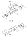
- FIG. 1 is an exploded view illustrating a configuration of a light source device according to Embodiment 1 of the present disclosure.
- the light source device is equipped with a light source part 31, a reflector 11, a housing 60, heat transfer bodies 20 and 21, heat-sink fins 71 and 72, and the like.
- the light source part 31 and the reflector 11 are housed in the housing 60, while the heat transfer bodies 20 and 21 and the heat-sink fins 71 and 72 are attached to both lengthwise ends of the housing 60 with screws 73, 74, 75, and 76.
- FIG. 2 is an exploded view illustrating a light source part of a light source device according to Embodiment 1.
- the light source part 31 comprises a light guide 4, a light guide cover 50, end holders 55 and 56, light emitter mounting substrates 92 and 94, and heat transfer bodies 18 and 19.
- the light guide 4 is made of a transparent resin and formed in a columnar shape whose central axis direction is the lengthwise direction.
- the central axis of the light guide 4 is designated the lengthwise direction of the light source device, while the direction orthogonal to the central axis is designated the widthwise direction.
- the long-edge direction of the housing 60 corresponds to the lengthwise direction
- the short-edge direction of the housing 60 corresponds to the widthwise direction.
- the light guide cover 50 is formed with a white resin, highly reflective metal, or the like, and a long groove is formed along the lengthwise direction. The midsection of the light guide 4 is placed into this long groove to hold the light guide 4 in the lengthwise direction. The open side of this long groove forms an output area that outputs light from the light guide 4.
- FIG. 3 is a plan view as seen from the light output direction of a light source device according to Embodiment 1.
- FIG. 4 is a cross-section view as seen in the widthwise direction of a light source device according to Embodiment 1.
- the end holders 55 and 56 respectively hold the ends of the light guide 4 and the light emitter mounting substrates 92 and 94, and suppress the output of unintentional light from the light emitters 91 and 93 (see FIG. 4 ).
- a lengthwise end of the light guide 4 is inserted into the end holder 55 (56), in which is formed a through-hole that slidably holds the light guide 4.
- Wavelength characteristics may also be adjusted by placing a thin optical device with wavelength-converting properties, such as a filter, between the light emitter 91 (93) and the light guide 4.
- the location corresponding to the open side of the columnar side face of the light guide 4 in the long groove of the light guide cover 50 preferably projects out farther towards the light guide 4 than other locations around the through-hole.
- the light emitter 91 (93) is a light source element such as an LED light source that inputs light from an end face on one side of the light guide 4.
- the light emitter 91 (93) is affixed by soldering or the like to the light emitter mounting substrate 92 (94), and is current-drive by the light emitter mounting substrate 92 (94) to emit light.
- Light input into the end face of the light guide 4 from the light emitter 91 (93) is guided in the lengthwise direction of the light guide 4, and output from the side face of the light guide 4 on the open side of the long groove in the light guide cover 50.
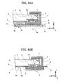
- FIG. 5A is a cross-section view as seen in the lengthwise direction of the center of a light source device according to Embodiment 1.
- FIG. 5B is a cross-section view as seen in the lengthwise direction of the positions of wings and fins of a light source device according to Embodiment 1.
- the light guide 4 has an approximately circular cross-section, and the side-face shape is cylindrical and includes a reflective area 41 and a reflective area 42 in two locations extending along the entire lengthwise direction.
- the side-face shape of the light guide 4 is not limited to a cylinder, and the end face of the light guide 4 is not limited to a circle.
- the reflector 11 laid parallel to the light guide 4 in the lengthwise direction, reflects secondary light output from the light guide 4, and irradiates in the direction of a document receptacle.
- the reflector 11 comprises a vapor-deposited metal face or the like, and is a thin plate or sheet extending in the lengthwise direction.
- the reflector 11 is kept at a suitable distance and angle with respect to the light guide 4 and the document receptacle by being affixed to a reflector installation face 69 of the housing 60 by adhesive bonding or the like.
- the light guide cover 50 holds the light guide 4 at a suitable position with respect to the reflector 11 and the housing 60.
- the light guide cover 50 reflects bleeding light from the side face or the back face of the reflective area 41 and the reflective area 42 towards the light guide 4, and suppresses the output of unintentional light from other than an output area 43 and an output area 44 (see FIG. 8 ).
- the light guide cover 50 includes a screw hole 51 formed in the lengthwise center and on the side opposite the reflector 11 in the widthwise direction (the side of the fins 68 of the housing 60), and is affixed to the housing 60 by a screw 77.
- the light guide cover 50 is equipped with a pin (projection) 52 formed in the center part (lengthwise center) of the light guide cover, and a pin (projection) 53 and a pin (projection) 54 formed at both ends in the lengthwise direction.
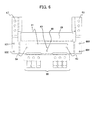
- FIG. 6 is a development view of a housing according to Embodiment 1.
- the housing 60 is formed by sheet metal with good heat dissipation, such as aluminum, and is formed into a box shape by being bent inwards along the two-dot chain lines in FIG. 6 .
- a floor having a rectangular shape, a long-edge wall and fins 68 bent out of the page in FIG. 6 on the long edge on one side of the floor, as well as a sloped face (reflector installation face 69) bent in the same direction at a designated angle from the short-edge direction of the floor on the long edge on the other side of the floor, to which the reflector 11 is affixed.
- short-edge walls bent in the same direction, and heat-sinks (wings 66 and 67), continuous with the short-edge walls, bent in the long-edge direction, and extending in the long-edge direction facing the opposite side of the long-edge wall with respect to the reflector installation face 69.
- heat-sinks may also be continuous with the long-edge wall side of the short-edge walls, bent in the long-edge direction, and extending in the long-edge direction facing the opposite side of the reflector installation face 69 with respect to the long-edge wall.
- the housing 60 is equipped with a bottom face, a wing 66 and a wing 67, fins 68, and a reflector installation face 69.
- a holding hole (interlocking hole) 62 and a screw hole 65 are formed in the lengthwise center, and a holding hole 63 and a holding hole 64 are formed at both lengthwise ends.
- the holding hole 63 and the holding hole 64 are long holes elongated in the lengthwise direction.
- an aperture 61 which is a hole extending along the lengthwise direction.
- screw holes 601, 602, 603, and 604 are formed on the short-edge walls of the housing 60.
- the light guide cover 50 is affixed to the bottom face of the housing 60 by aligning the screw hole 65 and the screw hole 51 (see FIG. 1 ), and penetrating the screw hole 51 and the screw hole 65 with the screw 77.
- the pin 52 is inserted into the holding hole 62, while the pins 53 and 54 are respectively inserted into the holding holes 63 and 64.
- the end holder 55 (56), the heat transfer body 18 (19), the heat transfer body 20 (21), and the heat-sink fins 71 (72) are affixed to a short-edge wall of the housing 60 by screws 73 and 74 (75 and 76) through screw holes 601 and 602 (603 and 604). Subsequently, the reflector 11 is affixed to the reflector installation face 69.
- the aperture 61 is a hole formed along the lengthwise direction positioned in the widthwise center part of the bottom face of the housing 60, and conveys light, which has been scattered and reflected by the object to be scanned from among the light radiated onto the object to be scanned, to an imager (a lens and image sensor), and suppresses all other unwanted light.
- the holding hole 62 is a round hole formed in the bottom face of the housing 60, and positioned in the center of the lengthwise direction and between the aperture 61 and the fins 68 in the widthwise direction.
- the pin 52 is inserted into the holding hole 62 when the screw hole 65 and the screw hole 51 are aligned and the light guide cover 50 is attached to the bottom face. By inserting the pin 52 of the light guide cover 50 into the holding hole 62, arbitrary parallel movement in the bottom-face direction of the light guide cover is restricted.
- the pin 52 and the holding hole 62 constitute an engaging part.
- the configuration of the interlocking part is not limited to the pin 52 and the holding hole 62.
- a projection may be formed on the bottom face of the housing 60, and a holding hole may be formed in the light guide cover 50.
- one hole may be threaded, and bolted from the other hole.
- the holding hole 63 (64) is a long hole elongated in the lengthwise direction, formed in the bottom face of the housing 60, and positioned at one end in the lengthwise direction and between the aperture 61 and the side of the fins 68 in the widthwise direction.
- the pin 53 (54) is inserted into the holding hole 63 (64) when the screw hole 65 and the screw hole 51 are aligned and the light guide cover 50 is attached to the bottom face.
- the pin 53 of the light guide cover 50 By inserting the pin 53 of the light guide cover 50 into the holding hole 63, movement of the light guide holder in the lengthwise direction is possible on the bottom face of the housing 60, while movement in the widthwise direction (the direction orthogonal to the lengthwise direction) is restricted.
- the pin 53 (54) and the holding hole 63 (64) constitute a restricting part.
- the configuration of the restricting part is not limited to the pin 53 (54) and the holding hole 63 (64).
- a projection may be formed on the bottom face of the housing 60, and a long hole in the lengthwise direction may be formed in the light guide cover 50.
- the round hole may be threaded, and bolted from the side of the other long hole.
- the wings 66 and 67 are positioned farther outward than the reflector 11 with respect to aperture 61, and extend the housing side face in the lengthwise direction.
- the wings 66 and 67 dissipate heat transferred from the light emitters 91 and 93 and the light emitter mounting substrates 92 and 94.
- the fins 68 are arranged on the housing side face at a position on the side opposite the reflector 11 with respect to the aperture 61.
- the fins 68 dissipate heat transferred from the light emitters 91 and 93 and the light emitter mounting substrates 92 and 94.
- the light guide cover 50 takes a suitable position at the following four points on the housing 60. Namely, the pin 52 is inserted into the holding hole 62, while the pin 53 and the pin 54 are respectively inserted into the holding hole 63 and the holding hole 64. In addition, the screw hole 51 and the screw hole 65 are affixed by the screw 77.
- the light guide cover 50 is shorter than the total length of the light guide 4.
- the end faces of the light guide cover 50 face the end faces of the end holder 55 and the end holder 56, and the gap length thereof is greater than the amount of expansion due to temperature change of the light guide cover 50.
- the holding hole 63 and the holding hole 64 are long holes, and the pin 53 and pin 54 are not affixed in the lengthwise direction, the light guide 4 is held in the widthwise direction without the light guide cover 50 bowing, even in the case in which the light guide cover 50 stretches due to temperature changes.
- the heat transfer bodies 18, 19, 20, and 21 are formed of sheet silicone, for example, have high adhesiveness and thermal conductivity, and work to transfer heat.
- the heat-sink fins 71 and 72 are fabricated by extrusion molding or the like from a metal with high thermal conductivity, such as aluminum. Heat from the light emitter 91 (93) and the light emitter mounting substrate 92 (94) is dissipated via the thermal conduction path of the heat transfer body 18 (19), the housing 60, the heat transfer body 20 ((21), and the heat-sink fins 71 (72).
- the housing 60 has a role of allowing heat from the light emitters 91 and 93 to diffuse.
- Heat from the light emitter 91 (93) is transferred to the light emitter mounting substrate 92 (94) from the junction plane of the light emitter 91 (93) and the light emitter mounting substrate 92 (94), transferred to the heat transfer body 18 from the junction plane of the light emitter mounting substrate 92 and the heat transfer body 18, transferred into the housing 60 from the junction plane of the heat transfer body 18 and the housing 60, and dissipated via a path that dissipates heat from the wing 66, the wing 67, and the fins 68 of the housing 60, as well as a path from the housing 60 to the heat transfer body 20 that dissipates heat from the heat transfer body 20 via the heat-sink fins 71, and a path from the housing 60 to the heat transfer body 21 that dissipates heat from the heat transfer body 21 via the heat-sink fins 72.
- FIG. 7A is a diagram illustrating a light path in the lengthwise direction of a light source device according to Embodiment 1.
- FIG. 7B is an enlarged view of the ends in FIG. 7A .
- FIG. 8 is a diagram illustrating a light path in the widthwise direction of a light source device according to Embodiment 1.
- light input into the light guide 4 from the light emitter 91 (93) proceeds while being repeatedly reflected off the side face of the light guide 4, and part of the light is incident on the reflective area 41 and the reflective area 42 having a white printed pattern or uneven shape formed along the lengthwise direction of the light guide 4.
- the end holders 55 and 56 form a shape in which a portion corresponding to the open side of the groove in the light guide cover 50 projects farther outward towards the light guide 4 compared to other portions, non-uniform light at the ends of the light guide 4 is not output from the light guide 4.
- FIG. 9A is a cross-section view as seen in the widthwise direction near a light emitter of a light source device according to Embodiment 1.
- FIG. 9B is a cross-section view illustrating an expanded state of the light guide and the light guide cover in FIG. 9A.
- FIG. 9A is a cross-section view at normal temperature, while FIG. 9B is a cross-section view at high temperature.
- the distances of the housing 60, the heat transfer body 18, the light emitter mounting substrate 92, the light emitter 91, and the end holder 55 are nearly constant.
- the degree of interlocking between the light guide 4 and the end holder 55, as well as the relative positions of the light guide cover 50 and the end holder 55 vary according to temperature changes.
- the light guide 4 and the end holder 55 expand, and the spacing between the light guide 4 and the light emitter 91, as well as the spacing between the light guide cover 50 and the end holder 55, narrow compared to normal temperature.
- the holding holes 63 and 64 of the housing 60 have a margin corresponding to the amount of temperature-related stretching of the light guide cover 50 in the lengthwise direction, and since the light guide cover is able to stretch in the lengthwise direction, the light guide 4 and the light guide cover 50 do not vary in the height direction and the widthwise direction. In other words, a configuration whose illumination characteristics do not change is obtained.
- the central axis of the columnar part of the light guide 4 is likewise designated the lengthwise direction of the light source device, while the direction orthogonal to the central axis is designated the widthwise direction.
- the lengthwise direction of the lengthwise direction is anticipated to be the main scanning direction of the image scanning device, while the widthwise direction is anticipated to be the sub scanning direction.
- three axes labeled X, Y, and Z are indicated in FIGS. 10 to 56 . Of these, the X axis represents the lengthwise direction (long-edge direction, main scanning direction).
- the Y axis represents the widthwise direction (short-edge direction, sub scanning direction). Meanwhile, the Z axis represents the thickness direction (height direction, illumination depth direction) of the light source device and the reflector support structure. Note that in the drawings, the same signs are given to the same or similar parts.
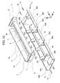
- FIG. 10 is an exploded perspective view of a light guide and nearby in a light source device according to Embodiment 2 of the present disclosure.
- FIG. 11 is a development view of a planar member that forms the housing of a light source device according to Embodiment 2.
- FIG. 12 is an exploded perspective view of a light source device according to Embodiment 2.
- the light source device comprises light-emitting parts 3, a light guide 4, a light guide holder 5, optical filters 6, support parts 7, and a reflector 11, which are housed in a housing 8.
- the light-emitting parts 3 comprise a light-emitting element 1 and a substrate 2.
- the light-emitting elements 1 are light sources such as LEDs that produce light at visible or non-visible wavelengths, or both.
- the light-emitting elements 1 are mounted on one face of the substrates 2. Light from the light-emitting elements 1 is transmitted through the optical filters 6 and input into the end faces 4a of the light guide 4.
- the light guide 4 is a columnar shape whose central axis direction is the lengthwise direction. The light guide 4 guides light input from the end faces 4a in the lengthwise direction, and outputs light from a side face of the columnar shape.
- the light guide 4 is preferably made of a transparent resin.
- holes are formed in both lengthwise ends of the light guide holder 5. These holes cover the circumference of the end faces 4a of the light guide 4.
- the light guide holder 5 covers the ends of the light guide 4, including the end faces 4a, except for at least one part of the end faces 4a of the light guide 4 (a portion necessary to input light from the light-emitting elements 1) and the side face of the portion that outputs light.
- the portion of the light guide holder 5 that faces opposite the light guide 4 preferably has a color with good reflectivity, such as white, but is not limited thereto.
- the light guide holder 5 locks the light guide 4 with light guide locking parts 5a. Note that Embodiment 2 anticipates the case of using resin with the same or approximately the same expansion ratio for the light guide 4 and the light guide holder 5.
- the support parts 7 there is formed a through-hole that penetrates from a first opening formed in one face to a second opening formed in the other face.
- the support parts 7 hold the ends of the light guide holder 5 on the side of the first opening so as to allow sliding in the lengthwise direction.
- the portion of the ends of the light guide holder 5 that cover the ends of the light guide 4 are inserted into the first opening of the support parts 7.
- the optical filters 6 are filters that convert the wavelength characteristics of light, and are formed using glass, a PET resin sheet, or the like as a base material.
- the optical filters 6 filter light from the light-emitting parts 3 (light-emitting elements 1), or alternatively, generate excited light from the light from the light-emitting parts 3 (light-emitting elements 1).
- Light transmitted through the optical filters 6 may also be complex light that includes excited light and light at unconverted wavelengths.
- the optical filters 6 obtain excitation light using a phosphor or the like, or remove unwanted wavelengths like a band-pass filter.
- the optical filters 6 are affixed to the support parts 7 by adhesive bonding or the like.
- the light from the light-emitting elements 1 include secondary optical wavelengths other than the target wavelengths of the light source device, it is necessary to insert the optical filters 6 that block the unwanted wavelength band in the light path.
- Heat transfer bodies 9 transfer heat from the substrates 2 to the housing 8.
- the heat transfer bodies 9 include grease-like materials in addition to sheets, and are formed from a thermally conducting compound or the like, for example.
- the support parts 7 are placed between the substrates 2 and the heat transfer bodies 9, and fastened to the housing 8 with screws 10.
- Screw holes for the screws 10 are drilled into the support parts 7, the substrates 2, and the heat transfer bodies 9 (in the case of sheets).
- the screw holes in the substrates 2 and the heat transfer bodies 9 may also be simple, unthreaded through-holes.
- the heat transfer bodies 9 may also be omitted.
- the reflector 11 laid parallel to the light guide 4 in the lengthwise direction, reflects part of the light output from the light guide 4 (secondary light), and radiates the light in the direction of the document receptacle of the image scanning device (not illustrated).
- An object to be scanned by the image scanning device such as a document or banknote, is placed on or in the document receptacle.
- the reflector 11 comprises a vapor-deposited metal face or the like, and is a thin plate or sheet extending in the lengthwise direction of the light guide 4.
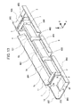
- FIG. 13 is a perspective view of a light source device according to Embodiment 2.
- FIG. 13 illustrates a state in which the light-emitting parts 3, the light guide 4, the light guide holder 5, the optical filters 6, the support parts 7, the heat transfer bodies 9, the reflector 11, and the like have been assembled in the housing 8.
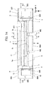
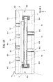
- FIG. 14 is a plan view of a light source device according to Embodiment 2.
- FIG. 14 illustrates the projection direction expressed by the subsequent side views, and the position of cross-sections expressed by the cross-section views.
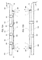
- FIG. 15A is a side view of a light source device as seen from the direction of the arrow A in FIG. 14 .
- FIG. 15B is a side view of a light source device as seen from the direction of the arrow B in FIG. 14 .
- FIG. 16A is a side view of a light source device as seen from the direction of the arrow C in FIG. 14 .
- FIG. 16B is a side view of a light source device as seen from the direction of the arrow D in FIG. 14 .
- the housing 8 supports the light guide holder 5 and the support parts 7.
- the housing 8 is preferably formed from a planar member 8a, and formed by sheet metal processing.
- the housing 8 indirectly supports the light guide 4 and the optical filters 6. It may also be said that the substrates 2 are indirectly supported by the housing 8 in the case in which the substrates 2 are not contacting the housing 8.
- Reflector support parts 801 are portions that support the reflector 11.
- the reflector support parts 801 comprise multiple intermittent portions along the lengthwise direction.
- the reflector support parts 801 are sloped with respect to the bottom face of the housing 8, and thus are also designated sloped faces 801.
- the reflector 11 is kept at a suitable distance and angle with respect to the light guide 4 and the document receptacle by being affixed to the reflector support parts 801 by adhesive bonding or the like.
- Light guide holder affixing parts 802 are portions that press in the widthwise direction to support the light guide holder 5.
- a plurality of light guide holder affixing parts 802 are intermittently formed along the main scanning direction (lengthwise direction).
- the light guide holder affixing parts 802 may also be singular. With the light guide holder affixing parts 802 and the bottom face of the housing 8 (the floor having a rectangular shape), the housing 8 holds the light guide holder 5 therebetween.
- Fastening parts 806 are portions to which the light guide holder 5, the light-emitting parts 3, and the heat transfer bodies 9 are fastened by the screws 10. Screw holes that allow the passage of the screws 10 are formed in the fastening parts 806.
- FIG. 11 illustrates a pre-bending planar member 8a of the housing 8 of a light source device according to Embodiment 2.
- the housing 8 is formed by a sheet metal with good heat dissipation, such as aluminum.
- the planar member 8a is provided with cut-outs or openings (holes) for forming long holes 8b, an interlocking hole 8c, the reflector support parts 801 (planar ends 803), light guide holder affixing parts 802 (planar ends 804), screw holes 805, the fastening parts 806, and a reflected light passage hole 807.
- the planar member 8a illustrated in FIG. 11 is bent in valley folds along the one-dot chain lines, but in the portions corresponding to the reflector support parts 801, the one-dot chain lines on the outermost periphery of the planar member 8a are bent in mountain folds in order to support the reflector 11. Since the expressions “valley folds” and “mountain folds” are relative expressions with respect to the face (front face) of the planar member 8a illustrated in FIG. 11 , the folding directions of the valley folds and mountain folds are reversed in the case of viewing the reverse face (back face) of the face (front face) of the planar member 8a illustrated in FIG. 11 .
- a box-shaped housing (housing 8) whose cross-section in the sub scanning direction (short-edge direction) is U-shaped.
- a floor bottom face
- long-edge walls plane ends 803, planar ends 804 bent inwards on the long edge of the floor.
- reflector support parts 801 bent inwards at a designated angle from the widthwise direction of the floor on the long edge on one side of the floor, and short-edge walls (fastening parts 806) bent inwards on the short edges of the floor.
- heat-sinks continuous with the short-edge walls, bent in the lengthwise direction, and extending in the lengthwise direction facing in the direction opposite the long-edge walls with respect to the sloped faces 801 (reflector support parts 801) may also be formed (see Embodiment 1).
- a screw holes 805 are holes that allow the passage of screws for attaching the housing 8 of the light source device to the image scanning device body (or alternatively, a carriage of the image scanning device). Note that the portion near the screw holes 805 and the screw holes 805 may be eliminated, and the fastening parts 806 may be provided as side faces along the widthwise direction of the lengthwise ends of the housing 8.
- the reflected light passage hole 807 is an aperture allowing passage of reflected light from light radiated onto the object to be scanned by the image scanning device (such as a document or banknote).
- the transport direction of the object to be scanned is the widthwise direction of the light source device (the sub scanning direction of the image scanning device, simply designated the sub scanning direction).
- the main scanning direction and the sub scanning direction intersect each other, and most typically are orthogonal.
- Projections formed on the light guide holder 5 are inserted into the long holes 8b and the interlocking hole 8c.
- the long holes 8b and the interlocking hole 8c By interlocking the long holes 8b and the interlocking hole 8c with the projections on the light guide holder 5, movement in the direction of the junction plane of the light guide holder 5 with the housing 8 is restricted.
- a detailed structure of a light source device will be described.
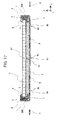
- FIG. 17 is a cross-section view of a light source device according to Embodiment 2.
- FIG. 17 illustrates the cross-section along the line E-F in FIG. 14 .
- a projecting part 4d is formed on the underside near the center of the light guide 4 (the bottom face side of the housing 8 .
- the light guide holder 5 is equipped with first projecting parts 5b respectively formed at both ends in the lengthwise direction, and a second projecting part 5c formed near the center in the lengthwise direction.
- the light guide holder 5 there is formed an interlocking hole 5d at the position of the projecting part 4d when the light guide 4 is engaged.
- the projecting part 4d of the light guide 4 is inserted into the interlocking hole 5d.
- the projecting part 4d is inserted into and interlocked with the interlocking hole 5d of the light guide holder 5, and both ends are respectively placed inside the holes at both ends of the light guide holder 5. Movement of the light guide 4 in the lengthwise direction near the center of the light guide 4 is restricted by the light guide holder 5 (interlocking hole 5d) due to the projecting part 4d.
- both ends of the light guide 4 are inserted into the holes of the light guide holder 5 and slidably supported, stretching of the light guide 4 in the lengthwise direction in accordance with temperature changes is not limited by the light guide holder 5.
- the light guide locking part 5a is a member that does not affix lengthwise expansion and contraction of the light guide 4, but restricts lengthwise bowing and sagging of the light guide 4, and is a member that keeps the light guide 4 from disengaging from the light guide holder 5. Since it is sufficient for the light guide 4 and the light guide holder 5 to have a mutually interlocking mechanism, the relationship between the projecting part 4d and the interlocking hole 5d may be reversed, such that an interlocking hole is formed in the light guide 4, and a projecting part is formed on the light guide holder 5.
- the second projecting part 5c and the interlocking hole 8c constitute an engaging part.
- the first projecting parts 5b and the long holes 8b constitute restricting parts.
- the configuration of the engaging part is not limited to the second projecting part 5c and the interlocking hole 8c, nor is the configuration of the restricting parts limited to the first projecting parts 5b and the long holes 8b, similarly to Embodiment 1.
- the relationship between the second projecting part 5c and the interlocking hole 8c may be reversed, such that an interlocking hole is formed in the light guide holder 5, and a second projecting part is formed on the housing 8. This applies in the same way to the relationship between the first projecting parts 5b and the long holes 8b.
- two pins are formed on the reverse face (second opening side) of the face into which the light guide holder 5 is inserted into the support parts 7 (first opening side). Additionally, in correspondence with these pins, pin holes are formed in each of the substrates 2 and the heat transfer bodies 9. The substrates 2 and the heat transfer bodies 9 are aligned, the pins of the support parts 7 are passed into the pin holes, and the substrates 2, the heat transfer bodies 9, and the support parts 7 are affixed to the fastening parts 806 of the housing 8 with the screws 10. By interlocking the two pins and pin holes, the light-emitting elements 1 are positioned facing the end faces 4a at the position of the second opening. Also, the heat transfer bodies 9 are positioned with respect to the substrates 2. Hereinafter, a method of affixing the light guide holder 5 and the support parts 7 to the housing 8 will be described.
- the light guide 4 is made to engage with the light guide holder 5, and both ends of the light guide holder are inserted into the first opening of the support parts 7.
- the optical filters 6 are held between the end faces 4a of the light guide 4 and the light-emitting elements 1, while the substrates 2 and the heat transfer bodies 9 are provisionally joined to the support parts 7.
- the second projecting part 5c of the light guide holder 5 is inserted and interlocked with the interlocking hole 8c of the housing 8.
- the first projecting parts 5b of the light guide holder 5 are simultaneously inserted into the long holes 8b of the housing 8.
- the first projecting parts 5b are able to move in the lengthwise direction within the range of the long holes 8b. Consequently, the position of the light guide holder 5 in the lengthwise direction may be kept in a state along the main scanning direction of the light source device.
- the screws 10 are used to affix the support parts 7 to the fastening parts 806 of the housing 8.
- the substrates 2 and the heat transfer bodies 9 are also fastened to the support parts 7 by the screws 10.
- the heat transfer bodies 9 are formed with sheet-like silicone sheets or the like that work to transfer heat, and have high adhesiveness and thermal conductivity.
- the heat transfer bodies 9 are placed between the substrates 2 and the fastening parts 806.
- the housing 8 has a role of allowing heat from the light-emitting parts 3 (light-emitting elements 1, substrates 2) to diffuse. Heat produced from the light-emitting parts 3 passes through the substrates 2 and is transferred to the fastening parts 806 via the heat transfer bodies 9.
- FIGS. 13 to 16 illustrate a light source device after affixing the light guide holder 5 and the support parts 7 to the housing 8.
- the fastening parts 806 fastening the light-emitting parts 3 may be referred to as that which fastens, either directly or via the heat transfer bodies 9, to the portion of the housing 8 (planar member 8a) that is bent in the lengthwise direction.
- the planar ends 803 and the planar ends 804 are lower than the height of the light guide holder 5, the support parts 7, and the reflector 11 in the thickness direction (Z direction).
- the dimensions of the housing 8 (planar member 8a) may also be changed so that the planar ends 803 and the planar ends 804 are higher than the light guide holder 5, the support parts 7, and the reflector 11.
- the light guide holder 5 covers the light guide 4 throughout the lengthwise direction, except for at least side faces 4b (light output parts 4b) from which the light guide 4 outputs light.
- the light guide holder 5 includes two first projecting parts 5b, and is placed onto the housing 8 extending in the lengthwise direction.
- the housing 8 includes two long holes 8b formed in the lengthwise direction, and the first projecting parts 5b are inserted into the long holes 8b.
- the light guide holder 5 includes a second projecting part 5c
- the housing 8 includes an interlocking hole 8c formed on the reverse side of the side of the light-emitting parts 3 in the lengthwise direction with respect to the long holes 8b.
- the second projecting part 5c is inserted into the interlocking hole 8c. Since the second projecting part 5c is formed in the center part of the light guide 4 in the lengthwise direction, the light guide 4 expands and contracts from the center part of the light guide 4 as a point of origin, even in the case in which the light guide 4 and the light guide holder 5 expand or contract according to surrounding temperature changes.
- the second projecting part 5c and the interlocking hole interlocking hole 5d of the light guide holder 5 may be placed so as to be included in the same cross-section in the sub scanning direction (widthwise direction).
- the second projecting part 5c is formed in the center part of the light guide 4 in the lengthwise direction, and thus the length of the light guide 4 projecting out from the light guide holder 5 becomes the same length at both ends of the light guide holder 5. Accordingly, taking the length of a projecting light guide 4 into account, the positional relationship between the light guide holder 5 and the support parts 7 (the positions of the optical filters 6 inside the support parts 7) may be set so that the light guide 4 and the support parts 7 (optical filters 6) do not contact.
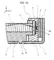
- FIG. 18 is a cross-section view near a light-emitting part as seen in the widthwise direction of a light source device according to Embodiment 2.
- FIG. 18 illustrates the cross-section along the line E-F in FIG. 14 .
- a light source device according to Embodiment 2 places light-emitting elements 1 (light-emitting parts 3) in the second opening of the support parts 7.
- a state is then reached in which the optical filters 6 between the first opening and the second opening of the support parts 7 are supported while maintaining a designated spacing with the light-emitting elements 1 (light-emitting parts 3).
- Embodiment 2 describes an example in which the light-emitting parts 3 and the support parts 7 are formed at both end faces of the light guide 4, a light-emitting part 3 and a support part 7 may also be formed at one end face of the light guide 4.
- the second opening may be sealed on the end of the light guide 4 without a light-emitting part 3, and a support part 7 lacking a light-emitting part 3 may be placed.
- a reflecting member may be formed instead of an optical filter 6 inside a support part 7 (including the end face of the light guide 4) in this state.
- FIG. 19 is a cross-section view as seen in the lengthwise direction of a light source device according to Embodiment 2.
- FIG. 19 illustrates the cross-section along the line G-H in FIG. 14 .
- At least one line of a light scattering pattern 4c is continuously or intermittently formed in the light guide 4 throughout the main scanning direction.
- the light output parts 4b are portions that face opposite the light scattering patterns 4c in the light guide 4.
- the light output parts 4b are likewise arranged in two lines in the main scanning direction. Depending on the positional relationship between the two lines of light scattering patterns 4c, some or all of the areas of the two lines of light output parts 4b may overlap.
- the light scattering patterns 4c are formed in a portion that at least corresponds to an effective scanning area in the main scanning direction of the image scanning device.
- the light source device is used for illumination of an image scanning device.
- FIG. 19 illustrates a scanning device platen (document receptacle) and an object to be scanned by the image scanning device.
- the light-emitting parts 3 are light source elements (light-emitting elements 1) such as LED light sources that input light from the end faces 4a of the light guide 4, are affixed to the substrates 2 by soldering or the like, and emit light as a result of being current-driven via traces or wiring on the substrates 2.
- the illustration of traces or wiring inside and outside the substrates 2 is omitted from the drawings.
- light-emitting elements 1 light-emitting parts 3
- light at a specific wavelength is selected (or light at a specific wavelength is blocked) by the optical filters 6, and light is input into the light guide 4 from light input parts 4a (end faces 4a).
- excitation light produced by the optical filters 6 (which may also be complex light that also includes light with unconverted wavelengths) is input into the light guide 4 from the end faces 4a.
- Light from the light-emitting elements 1 input via the optical filters 6 is guided in the lengthwise direction while reflecting off the side faces inside the light guide 4.
- the solid arrow in FIG. 18 illustrates an example of a light path of light emitted from a light-emitting element 1.
- the light guide 4 is formed with a transparent resin in a columnar shape whose axis direction is the lengthwise direction, has a cylindrical side-face shape, and includes two lines of light scattering patterns 4c that extend throughout the lengthwise direction.
- the light is output from the light output parts 4b on the side face of the light guide 4 that face opposite the light scattering patterns 4c.
- Light output from other than the light output parts 4b is reflected off the light guide holder 5 and re-input into the interior of the light guide 4.
- the light scattering patterns 4c may be printed onto the light guide 4, or be prism patterns that make the surface of the light guide 4 uneven.
- the shape of the light scattering patterns 4c obviously may be varied in the main scanning direction.
- the side-face shape of the light guide 4 is not limited to a cylinder, and the end face of the light guide 4 is not limited to a circle.
- Light (secondary light) output from the other light output part 4b proceeds approximately parallel to, or at a shallow angle with respect to the light output from the first light output part 4b, with respect to the sub scanning direction, is reflected by the reflector 11, and irradiates the object to be scanned via the platen (transparent plate) of the scanning device.
- the reflector 11 has a surface comprising a mirror face such as vapor-deposited metal face, and is a thin plate or sheet extending in the lengthwise direction (X direction).
- the reflector 11 keeps a suitable distance and angle with respect to the light guide 4, the platen (transparent plate) of the scanning device, and the object to be scanned.
- light is differentiated into “primary light” and “secondary light” depending on the light path, this does not denote a superiority or inferiority in various parameters of the light, such as intensity or brightness.
- Light output from the light guide 4 and radiated onto the object to be scanned reflects off the object to be scanned, and via the reflected light passage hole 807, is formed into an image through the image-forming optical system of the scanning device, and converted into data by a light sensor.
- the image-forming optical system may be a reducing optical system, an erecting life-size optical system, an off-axial optical system, a telecentric (bi-telecentric) optical system or the like, but is not limited to any of these.
- the platen of the scanning device is not required. In the case in which a platen exists, it is necessary to decide on the placement of the light output parts 4b and the light scattering patterns 4c of the light source device while accounting for the refractive index of the platen. Additionally, sub scanning of the object to be scanned may be taken to be transporting the object to be scanned itself (movement in the sub scanning direction), or transporting a carriage (image scanning device) mounted with the light source device (movement in the sub scanning direction).
- the image-forming optical system implemented in a light source device according to Embodiment 2 is an erecting life-size optical system
- a rod lens holding part that holds a rod lens may be placed.
- the one-dot chain line illustrated in FIG. 19 becomes the optical axis of the rod lens.
- a sensor substrate in the case in which the reflected light passage hole 807 does not hold a rod lens, a substrate with a light-sensing part (sensor) formed thereon at one of the focal points of the rod lens
- this sensor substrate may be configured to be directly or indirectly held by the housing 8.
- the housing 8 also doubles as the housing of the image scanning device.
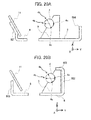
- FIG. 20A is a cross-section view along the line G-H in FIG. 14 .
- FIG. 20B is a cross-section view along the line I-J in FIG. 14 .
- the reflector support parts 801 are a plurality of members that are placed on the reverse face of the reflector 11 opposite the face that reflects light output from the side faces 4b of the light guide 4, arranged along the main scanning direction with a designated interval spaced therebetween, and support the reflector 11.
- the reflector support parts 801 are formed by respectively bending one end of the housing 8 along the main scanning direction.
- the multiple reflector support parts 801 are obtained by bending part of the planar member 8a that constitutes housing 8, and are thus integral with the housing 8, and may be referred to as members that stand off the bottom face of the housing 8 at an angle with respect to the sub scanning direction.
- the reflector support parts 801 may also be referred to as members that include a portion whose flat face in the main scanning direction is curved in the sub scanning direction.
- multiple reflector support parts 801 are formed on a light source device (reflector support structure) according to Embodiment 2, by adjusting the placement and sloping angle of each reflector support part 801 individually, it is possible easily obtain installation precision of the reflector 11 in the main scanning direction and the sub scanning direction. In other words, it becomes possible to avoid worsened installation precision of the reflector 11 due to bowing or sagging of a single plate in the main scanning direction and the sub scanning direction that is produced in the case of using a single plate as the support part for the reflector 11.
- the reflector 11 is supported by a plurality of reflector support parts 801 arranged intermittently along the main scanning direction, it is possible to minimize sagging due to the weight of the reflector 11 itself, which may occur in the case of supporting the reflector 11 only at the ends of the reflector 11.
- the plurality of reflector support parts 801 include a portion curved with respect to the sub scanning direction besides the base end portion having an angle with respect to the housing 8. In other words, the housing 8 is bent in two locations.
- the portions other than the plurality of reflector support parts 801 form a plurality of planar ends 803 that are respectively continuous with the bottom face. Because of the bent planar ends 803, the strength of the housing 8 is raised, and bowing or sagging is less likely.
- planar ends 803 in the main scanning direction (X direction) longer than the length of the reflector support parts 801 in the main scanning direction, it is possible to increase the surface area allowing that formation of screw holes (screw holes having the same function as the screw holes 805) for connecting with (the carriage of) the image scanning device.
- the strength of the planar ends 803 as connection members rises.
- the strength of the reflector support structure also rises.
- the planar ends 803 may also be referred to as members that include a portion whose flat face in the main scanning direction is curved in the sub scanning direction.
- the light guide holder affixing parts 802 that affix the light guide holder 5 comprise a plurality of members arranged at designated intervals along the lengthwise direction.
- the light guide holder affixing parts 802 may also be singular.
- the light guide holder affixing parts 802 are formed by respectively bending the ends along the long edge of the planar member 8a on the light guide holder 5 side in two locations.
- the plurality of light guide holder affixing parts 802 are obtained by bending the planar member 8a, and are thus integral with the housing 8, similarly to the reflector support parts 801, and may be referred to as members that stand off the bottom face of the housing 8 at an angle with respect to the widthwise direction.
- the light guide holder affixing parts 802 may also be referred to as members that include a portion whose flat face in the main scanning direction is curved in the sub scanning direction.
- the portions other than the plurality of light guide holder affixing parts 802 form a plurality of planar ends 804 that are respectively continuous with the bottom face. Because of the bent planar ends 804, the strength of the housing 8 is raised, and bowing or sagging is less likely.
- planar ends 804 in the main scanning direction (X direction) longer than the length of the light guide holder affixing parts 802 in the lengthwise direction, similarly to the planar ends 803, it is possible to increase the surface area allowing that formation of screw holes (screw holes having the same function as the screw holes 805) for connecting with (the carriage of) the image scanning device.
- the strength of the planar ends 804 as connection members rises.
- the strength of the reflector support structure also rises.
- the planar ends 804 may also be referred to as members that include a portion whose flat face in the main scanning direction is curved in the sub scanning direction.
- the light guide 4, the light guide holder 5, and the support parts 7 are placed while accounting for expansion and contraction in the thickness direction of the light guide 4 and the light guide holder 5 of a light source device according to Embodiment 2.
- the dimensions of the light guide holder 5 and the support parts 7 are set so that, at the maximum anticipated expansion, the light guide holder 5 does not damage the support parts 7.
- the influence is extremely small compared to expansion and contraction in the lengthwise direction of the light guide 4 and the light guide holder 5.
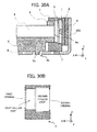
- FIG. 21A is a cross-section view near a light-emitting part that corresponds to the cross-section along the line E-F in FIG. 14 of a light source device according to Embodiment 2.
- FIG. 21B is a cross-section view of a support part according to Embodiment 2.
- the support parts 7 include a communicating first opening (the portion indicated by the dotted arrow in FIG. 21B ) and a second opening (the portion indicated by the dotted arrow in FIG. 21B ).
- the support parts 7 hold the ends of the light guide holder 5 on the side of the first opening so as to allow sliding in the lengthwise direction.
- the light-emitting parts 3 (light-emitting elements 1 and substrates 2) are placed in the second opening of the support parts 7.
- the support parts 7 support the optical filters 6 between the first opening and the second opening while maintaining a designated spacing with the light-emitting parts 3.
- the optical filters 6 are supported by the support parts 7 outside of the range over which the end faces of the light guide move due to sliding of the ends of the light guide holder 5.
- the configuration is required to be limited to this placement. It is sufficient to place the light-emitting parts 3 so that light emitted from the light-emitting elements 1 (light-emitting parts 3) is input into the light guide 4 via the second opening and the first opening of the support parts 7.
- the support parts 7 have internally formed therein a first hollow part, a second hollow part, and a third hollow part whose diameters successively decrease proceeding from the side of the first opening to the side of the second opening, and support the optical filters 6 inside the second hollow part.
- the optical filters 6 are placed in the step portion produced between the second hollow part and the third hollow part. Note that the depth of the second hollow part is taken to be equal to or greater than the thickness of the optical filters 6.
- the light guide holder 5 is formed with a white resin or highly reflective metal or the like, includes a groove configured as a long groove in the lengthwise direction, and holds the light guide 4 in the lengthwise direction as a result of the light guide 4 being placed into this groove.
- the open side of this groove forms output areas (light output parts 4b) that output light from the light guide 4.
- the light guide holder 5 holds the light guide 4 at a suitable position with respect to the reflector 11 and the housing 8.
- the light guide holder 5 reflects light output from a side face other than the light output parts 4b of the light guide 4 or from the back face of the light scattering patterns 4c back inside the light guide 4, and minimizes the output of unintentional light from other than the light output parts 4b.
- FIG. 22A is a cross-section view near a light-emitting part of a light source device according to Embodiment 2.
- FIG. 22B is a cross-section view near a light-emitting part that illustrates the case of a thermally expanded light guide and light guide holder in a light source device according to Embodiment 2.
- FIG. 22C is a central cross-section view of a light source device according to Embodiment 2.
- FIG. 22A illustrates the case of the smallest length of the light guide 4 in the lengthwise direction.
- FIG. 22B illustrates the case of the largest length of the light guide 4 in the lengthwise direction.
- FIG. 22C illustrates the second projecting part 5c and the interlocking hole 5d of the light guide holder 5 placed at the same position in the lengthwise direction.
- the inner wall shape of the first hollow part allows the portion of the light guide holder 5 inserted into the support parts 7 to contact the support parts 7 and the light guide holder 5 to slide. Alternatively, it is necessary to allow the light guide holder 5 to stretch without having the portion of the light guide holder 5 inserted into the support parts 7 to contact the support parts 7.
- the light guide holder 5 and the support parts 7 are disposed such that the end faces 4a of the light guide 4 and the end faces of the light guide holder 5 are contacting or about to contact at the step portion produced between the first hollow part and the second hollow part.
- the end faces 4a (light input parts 4a) of the light guide 4 and the light-emitting parts 3 (optical filters 6) may be made to not contact.
- the light guide holder 5 may include pushing face parts that face opposite the edges of the first opening, and these pushing face parts may be provided so as to restrict the sliding range (movement range) of the light guide holder 5 ( FIG. 22B ).
- the pushing face parts may also be made to be about to contact the edges of the first opening when the expansion of the light guide 4 is at maximum. In this case, the pushing face parts become opposing face parts rather than pushing face parts.
- the support parts 7 hold the substrates 2, the light guide holder 5, and the optical filters 6, and minimize the emission of unintentional light from the light-emitting parts 3.
- an end that includes the end face on one side of the light guide holder 5 is inserted into the first opening at the end face on one side of the support parts 7.
- the substrates 2 affixed with the light-emitting parts 3 are placed in the second opening at the end face on the other side of the support parts 7 so that the light-emitting elements 1 and the light guide 4 face opposite.
- the support parts 7 include a face that holds the optical filters 6 and a face that affixes the substrates 2, and keeps the distance between the optical filters 6 and the substrates 2 constant.
- the distance between the end faces of the ends of the light guide holder 5 inserted into the first opening and the optical filters 6 vary due to expansion or contraction of the light guide 4 (light guide holder 5), but the configuration is unaffected by stretching (expansion or contraction) of the light guide 4 (light guide holder 5). Consequently, the light-modulating characteristics of the optical filters 6 stabilize.
- the degree of interlocking (degree of insertion) between the light guide 4 and the support parts 7 as well as the relative positions of the light guide holder 5 and the support parts 7 vary.
- the light guide holder 5 is able to stretch in the lengthwise direction.
- the light guide 4 and the light guide holder 5 are not varied in the height direction and the widthwise direction. As a result, change in the illumination characteristics is minimized. Also, since the support parts 7 are affixed to the fastening parts 806 on the housing 8 in the lengthwise direction by the screws 10, the heat dissipation effects also do not change.
- the distances of the housing 8 (fastening parts 806), the heat transfer bodies 9, the substrates 2, the light-emitting elements 1, the support parts 7, and the optical filters 6 are fixed, and the distance between the light guide 4 and the light guide holder 5 is fixed (in the case of close expansion ratios).
- the portion of light blocked by the light guide holder 5 is fixed, and the effect of suppressing unwanted stray light produced at the ends of the light guide 4 is kept constant.
- the function of converting light from the light-emitting parts 3 is kept constant.
- the support parts 7 may be configured such that the ends of the light guide holder 5 and the support parts 7 do not contact, and the ends of the light guide holder 5 stretch in the lengthwise direction inside the first opening or above the first opening. Likewise in this case, the support parts 7 support the optical filters 6 outside the range over which the end faces 4a of the light guide 4 move due to stretching of the ends of the light guide holder 5.
- the support parts 7 slidably hold the ends of the light guide holder 5 inside the first hollow part, or alternatively, the ends of the light guide holder 5 stretch in the lengthwise direction inside the first hollow part.
- the light source device later illustrated in Modification 2.6 is also similar.
- the shape of the end faces 4a of the light guide 4 and the cross-sectional shape in the lengthwise direction of the light guide 4 in a light source device according to Embodiment 2 are not limited to a circular cross-section as illustrated in FIGS. 10 to 22 , and the cross-section may also be polygonal, gourd-shaped, or cocoon-shaped, and may also be an irregular shape, or alternatively, a combination of these.
- the shape of the portion of the light guide holder 5 inserted into the support parts 7 and inner shape of the portion of the support parts 7 into which the light guide holder 5 is inserted are not limited to a circular cross-section, and the cross-section may also be polygonal, gourd-shape, or cocoon-shaped, and may also be an irregular shape, or alternatively, a combination of these.
- the relationship between the light guide holder 5 and the support parts 7 is such that either the portion of the light guide holder 5 that is inserted into the support parts 7 contacts the support parts 7 and allows the light guide holder 5 to slide, or the portion of the light guide holder 5 that is inserted into the support parts 7 does not contact the support parts 7 and allows the light guide holder 5 to stretch. Even in the case in which the portion of the light guide holder 5 that is inserted into the support parts 7 does not contact the support parts 7, it is necessary to make the majority of light emitted from the light-emitting parts 3 not bleed from the gap between the support parts 7 and the light guide holder 5.
- the light guide holder 5 does not only hold the light guide 4, but also works to minimize unintentional light from the light-emitting parts 3 as well as the light guide 4.
- the light guide holder 5 takes a suitable position with the housing (housing 8) at the following three points on the housing 8. Namely, the three points are the two first projecting parts 5b and the two long holes 8b, and the second projecting part 5c and the interlocking hole 8c.
- the light guide holder 5 is shorter than the entire length of the housing 8.
- the end faces of the light guide holder 5 face opposite the end faces of the support parts 7, and the gap length therebetween is wider than the amount of expansion due to the temperature characteristics of the light guide holder 5.
- the light guide 4 is held without bowing or displacement in the widthwise direction, even in the case in which the light guide holder 5 stretches due to temperature changes.
- the light guide holder 5 holds the entire circumference of the ends of the light guide 4, and has an opening that exposes the light output parts 4b at the midsection. The portions of the light guide holder 5 that hold the entire circumference of the light guide 4 at the ends are inserted into the support parts 7.
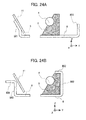
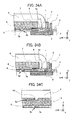
- FIG. 23 is a development view of a planar member that forms the housing of a light source device according to Modification 2.1 of Embodiment 2.
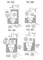
- FIG. 24A is a diagram that corresponds to the cross-section along the line G-H in FIG. 14 of a light source device according to Modification 2.1.
- FIG. 24B is a diagram that corresponds to the cross-section along the line I-J in FIG. 14 of a light source device according to Modification 2.1.
- FIG. 24A illustrates an end face corresponding to the cross-section along the line G-H in FIG. 14 , and thus the integral end 808 is not represented. Consequently, FIG. 24A is unchanged from FIG. 20A .
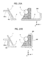
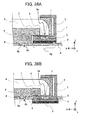
- FIG. 25A is a diagram that corresponds to the cross-section along the line G-H in FIG. 14 of a light source device according to Modification 2.2.
- FIG. 25B is a diagram that corresponds to the cross-section along the line I-J in FIG. 14 of a light source device according to Modification 2.2.
- the tip portion of the reflector support parts 801 is extended, forming extended reflector support parts 801e having an angle with respect to the face to which the reflector 11 is affixed.
- the reflector 11 affixing face of the reflector support parts 801 and the extended reflector support parts 801e are curved, and thus the strength of the reflector support parts 801 rises.
- the extended reflector support parts 801e the excess portion produced in the planar member 8a from the difference in dimensions between the housing 8 and the reflector 11.
- the housing 8 of Modification 2.2 includes extended planar ends 803e in which the tip portion of the planar ends 803 is extended. Since there is a curve between the planar ends 803 and the extended planar ends 803e, the strength of the planar ends 803 rises.
- screw holes screw holes having the same function as the screw holes 805) for connecting with (the carriage of) the image scanning device may be formed on the extended reflector support parts 801e or the extended planar ends 803e.
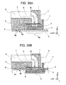
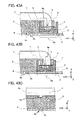
- FIG. 26A is a diagram that corresponds to the cross-section along the line G-H in FIG. 14 of a light source device according to Modification 2.3.
- FIG. 26B is a diagram that corresponds to the cross-section along the line I-J in FIG. 14 of a light source device according to Modification 2.3.
- extended planar ends 804e extending at an angle from the tip portion in the widthwise direction of the planar ends 804 are formed, in addition to the configuration of Modification 2.2.
- extended light guide holder affixing parts 802e extending at an angle from the tips in the widthwise direction of the light guide holder affixing parts 802 are formed.
- FIG. 26C is a diagram that corresponds to the cross-section along the line I-J in FIG. 14 , illustrating a difference example of a light source device according to Modification 2.3.
- the extended light guide holder affixing parts 802e are curved towards the light guide holder 5 starting at the tips of the light guide holder affixing parts 802. Since the extended light guide holder affixing parts 802e are curved towards the light guide holder 5 starting at the tips of the light guide holder affixing parts 802, not only does the strength of the light guide holder affixing parts 802 rise, but the affixing of the light guide holder 5 also becomes more secure.
- FIG. 26B and FIG. 26C The difference between FIG. 26B and FIG. 26C is the difference in the curve direction of the extended light guide holder affixing parts 802e with respect to the light guide holder affixing parts 802.
- the extended light guide holder affixing parts 802e of Modification 2.3 may be given the excess portion produced in the planar member 8a from the difference in dimensions between the housing 8 and the light guide holder 5.
- screw holes screw holes having the same function as the screw holes 805 for connecting with (the carriage of) the image scanning device may be formed on the extended planar ends 804e, similarly to the extended reflector support parts 801e and the extended planar ends 803e. Also, the cross-section of the portion of the reflector support parts 801 becomes FIG. 26A for both FIG. 26B and FIG. 26C .
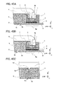
- FIG. 27A is a diagram that corresponds to the cross-section along the line G-H in FIG. 14 of a light source device according to Modification 2.4.
- FIG. 27B is a diagram that corresponds to the cross-section along the line I-J in FIG. 14 of a light source device according to Modification 2.4.
- the reflector support parts 801 are curved in two locations in mutually different directions from the bottom face of the housing 8.
- the reflector support parts 801b of Modification 2.4 are formed with a curve in one location from the bottom face of the housing 8.
- the reflector support parts 801b are formed with a curve in one location, it is possible to decrease the steps to process the planar member 8a Also, the angles for supporting the reflector 11 may be adjusted all at once. Furthermore, the integral end 808 of Modification 2.1, the extended reflector support parts 801e and extended light guide holder affixing parts 802e of Modification 2.2, or the extended planar ends 803e and the extended planar ends 804e of Modification 2.3 may also be added to Modification 2.4.
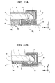
- FIG. 28A is a development view of a planar member that forms the housing of a light source device according to Modification 2.5.
- FIG. 28B is a diagram that corresponds to the cross-section along the line G-H in FIG. 14 of a light source device according to Modification 2.5.
- FIG. 28C is a diagram that corresponds to the cross-section along the line I-J in FIG. 14 of a light source device according to Modification 2.5.
- the reflector support structure of the light source devices up to Modification 2.4 is an element formed from the planar member 8a integrally with the light guide holder affixing parts 802, but in Modification 2.5, the reflector support structure and the light guide holder affixing parts are separated.
- a reflector support structure according to Modification 2.5 is formed by bending the planar member 8s illustrated in FIG. 28A .
- the differences between the planar member 8s according to Modification 2.5 and the planar member 8a are that the structure that supports the light guide holder 5 and the support parts 7 does not exist, and the reflected light passage hole 807 does not exist.
- the reflected light passage hole 807 may also be formed in the planar member 8s of Modification 2.5.
- the reflector support structure according to Embodiment 2 may be applied to a structure that supports a reflector (reflecting mirror, concave mirror, convex mirror) in an image-forming optical system of an image scanning device.
- the screw holes 805 may also be used to connect to members other than the carriage of an image scanning device.
- the plurality of reflector support parts 801 in Modification 2.5 are placed on the face on the reverse side of the reflective face of the reflector 11.
- the plurality of reflector support parts 801 are integral with the housing 8 that supports the reflector support parts 801.
- the flat faces in the main scanning direction of the reflector support parts 801 stand at an angle in the sub scanning direction with respect to the housing 8, and are respectively formed by bending one end of the planar member 8s along the main scanning direction.
- the structure of the housing 8 (planar member 8s) according to Modification 2.5 may be said to be only the reflector 11 side of the housing 8 (planar member 8a) of Embodiment 2 illustrated in FIGS. 13 and 17 , FIG. 19 , and FIG. 20 . Accordingly, it is possible to add the integral end 808 of Modification 2.1, or alternatively, the extended reflector support parts 801e or the extended planar ends 803e of Modification 2.2. Also, the reflector support parts 801 may be substituted with the reflector support parts 801b of Modification 2.4. Furthermore, after substituting in the reflector support parts 801b, the integral end 808, or alternatively, at least one of the extended reflector support parts 801e or the extended planar ends 803e, may also be added.
- a reflector support structure according to Modification 2.5 may also be carried out as only a reflector support structure for a reflector (first mirror, second mirror, and so on) within an image-forming optical system of an image scanning device.
- implementation is also possible as only a support structure for a reflector that reflects the secondary light discussed earlier.
- the source of light reflected by the reflector 11 may also be a rod-shaped light source or an array light source disposed opposite the reflector 11 and extending in the main scanning direction.
- the rod rod-shaped light source includes one that comprises the light-emitting parts 3 as well as the columnar light guide 4 that guides light from the light-emitting parts 3 input from the end faces 4a in the lengthwise direction, and outputs the light from the side faces 4b.
- a rod-shaped light source in a light source device may also be an electric-discharge lamp.
- the electric discharge lamp may be a typical one, such as an electric discharge lamp based on glow discharge such as a neon tube, or an electric discharge lamp based on arc discharge such as a fluorescent lamp or a xenon lamp (Xe lamp).
- An array light source in a light source device may be one in which the light-emitting parts 3 (light-emitting elements 1) are plurally arranged in the main scanning direction and emit light (secondary light) in the sub scanning direction, or one in which the light-emitting parts 3 (light-emitting elements 1) are plurally arranged in the main scanning direction, and emit light (secondary light) in the sub scanning direction with a light guide member or a reflective member.
- an array light source may emit primary light rather than secondary light, or emit both.
- an array light source arranged in separate columns may also be adopted.
- an array light source arranged for primary light and an array light source arranged for secondary light may become arranged in two columns along the main scanning direction.
- the two columns referred to herein include a staggered layout.
- FIG. 29A is a cross-section view near a light-emitting part of a light source device according to Modification 2.6.
- FIG. 29B is a cross-section view of a support part according to Modification 2.6.
- FIG. 30A is a cross-section view near a light-emitting part, illustrating a different example of a light source device according to Modification 2.6.
- FIG. 30B is a cross-section view of a support part according to a different configuration of Modification 2.6.
- the support parts 7 internally includes a first hollow part and a second hollow part whose diameters successively increase proceeding from the side of the first opening to the side of the second opening, and supports the optical filters 6 inside the second hollow part.
- the diameter of the second hollow part is greater than the diameter of the first hollow part, and a third hollow part whose diameter is smaller than the second hollow part is formed on the side of the second opening.
- there is no third hollow part and the substrate 2 side of the second hollow part is the second opening.
- the diameters of the second hollow part and the third hollow part may be seen as being equal.
- the optical filters 6 are placed in the step portion produced between the first hollow part and the second hollow part, or alternatively, in the step portion produced between the second hollow part and the third hollow part.
- the optical filters 6 are placed in the step portion produced between the first hollow part and the second hollow part.
- the light guide holder 5 and the support parts 7 cannot be disposed such that the end faces 4a of the light guide 4 and the end faces of the light guide holder 5 are contacting or about to contact at the step portion produced between the first hollow part and the second hollow part, as with the light source device illustrated in FIGS. 21 and 22 .
- the light source device and reflector support structure according to Embodiment 2 described using FIGS. 10 to 30 may be carried out by suitably substituting the respective configurations.
- Embodiment 2 is not limited to the example described using the drawings, namely, a configuration in which the support parts 7 slidably hold the ends of the light guide holder 5 inside the first hollow part. Since the light guide holder 5 is placed in the housing 8 and stands free without the support parts 7, it may be configured such that the support parts 7 and the light guide holder 5 do not contact, and the ends of the light guide holder 5 stretch in the lengthwise direction inside the first hollow part of the support parts 7 or above the first hollow part of the support parts 7.
- the housing 8 (housing) of a light source device according to Embodiment 2 is equipped with two long holes 8b formed at both ends in the lengthwise direction, and an interlocking hole 8c formed between the two long holes 8b, in the center part in the widthwise direction of the floor (bottom face) having a rectangular shape.
- an reflected light passage hole 807 (aperture) formed in the bottom face along the lengthwise direction screw holes 805, light guide holder affixing parts 802, reflector support parts 801, and fastening parts 806.
- the light guide holder 5 and the reflector 11 are affixed in the lengthwise direction, the widthwise direction, and the height direction, while the support parts 7 and the heat transfer bodies 9 are affixed in the lengthwise direction, the widthwise direction, and the height direction.
- the long holes 8b are long holes elongated in the lengthwise direction in the bottom face of the housing 8, positioned at either end in the lengthwise direction, between the reflected light passage hole 807 and the fastening parts 806 in the widthwise direction, and in the widthwise center of the bottom face of the light guide holder 5.
- the first projecting parts 5b of the light guide holder 5 are inserted into the long holes 8b, thereby restricting planar movement of the light guide holder 5 in the widthwise direction.
- the interlocking hole 8c is positioned in the housing 8 bottom face, on the side of the long holes 8b opposite the fastening parts 806 in the lengthwise direction, between the reflected light passage hole 807 and the light guide holder affixing parts 802 in the widthwise direction, and in a center position in the widthwise direction of the light guide holder 5.
- the second projecting part 5c of the light guide holder 5 is inserted into the interlocking hole 8c, thereby restricting arbitrary planar movement of the light guide holder 5 in the bottom face direction ( FIG. 17 ).
- the reflected light passage hole 807 is a hole formed along the lengthwise direction of the housing 8 bottom face, and works to convey image information about the object to be scanned (light among the radiated light that was scattered and reflected by the object to be scanned) to the imager (an image-forming optical system such as a lens and a light-sensing part such as an image sensor) ( FIG. 19 ), while minimizing all other unwanted light.
- the light guide holder affixing parts 802 extend along the side face on the side of the housing 8, are positioned on the side opposite the reflector 11 with respect to the reflected light passage hole 807, and work to affix the light guide holder 5 in the height direction.
- the reflector support parts 801 are multiply provided in the lengthwise direction, positioned farther outward than the reflected light passage hole 807 in the widthwise direction, and work to hold the reflector 11 with good precision.
- the fastening parts 806 are positioned outward in the lengthwise direction of the housing with respect to the reflected light passage hole 807, and affix the substrates 2, the support parts 7, and the heat transfer bodies 9 to the housing 8 with the screws 10.
- the reflector support parts 801, the light guide holder affixing parts 802, the planar ends 803, the planar ends 804, the fastening parts 806, and the integral end 808 in the housing 8 also perform the function of heat-sinks.
- the planar ends 803, the planar ends 804, the fastening parts 806, and the integral end 808 may be continuous at the side wall portion of the short-edge walls (fastening parts 806) of the housing 8.
- the short-edge walls may be extended and bent in the lengthwise direction, and extend in the lengthwise direction facing in the opposite direction of the reflector supports 801 with respect to the long-edge walls (planar ends 803).
- the short-edge walls (fastening parts 806) may be continuous with the long-edge walls and bent in the short-edge direction, and may be extended (bent) in the direction facing the bottom face of the housing 8.
- Embodiment 3 describes a case in which the light-emitting parts 3 are fastened to the bottom face of the housing 8 directly or via the heat transfer bodies 9, and a case in which the light-emitting parts 3 are attached via holes formed in the housing 8. Otherwise, the configuration is similar to Embodiment 2.
- the light guide 4, the light guide holder 5, and the support parts 7 are obviously placed while accounting for expansion and contraction in the thickness direction of the light guide 4 and the light guide holder 5.
- the dimensions of the light guide holder 5 (light guide 4) and the support parts 7 are set so that, at maximum expansion, the light guide holder 5 (light guide 4) does not damage the support parts 7.
- the influence is extremely small compared to expansion and contraction in the lengthwise direction of the light guide 4 and the light guide holder 5.
- FIG. 31 is a development view of a planar member that forms the housing of a light source device according to Embodiment 3 of the present disclosure.
- FIG. 32A is a cross-section view near a light-emitting part of a light source device according to Embodiment 3.
- FIG. 32B is a cross-section view near a light-emitting part that illustrates the case of a thermally expanded light guide and light guide holder in a light source device according to Embodiment 3.
- FIG. 32C is a central cross-section view of a light source device according to Embodiment 3.
- FIGS. 31 to 32C illustrate the case in which the light-emitting parts 3 are fastened to the bottom face of the housing 8.
- FIG. 31 illustrates a state of virtually placing the light guide 4, the light guide holder 5, and the support parts 7 on top of the housing 8.
- the ends of the light guide 4 are curved towards areas 8g of the housing 8 bottom face.
- the light guide holder 5 covers the ends of the light guide 4, except for at least a part of the end faces 4a.
- a first hollow part and a second hollow part whose diameters successively decrease from above (farther away from the bottom face of the housing 8) are formed in the direction in which the ends of the light guide 4 curve.
- the side of the first hollow part that abuts the end faces 4a of the light guide 4 is a first opening, while the side of the second hollow part on the bottom face of the housing 8 is a second opening.
- the light-emitting parts 3 (light-emitting elements 1 and substrates 2) and the heat transfer bodies 9 are affixed between the second opening and the areas 8g.
- the support parts 7 support the optical filters 6 between the first opening and the second opening while maintaining a designated spacing with the light-emitting parts 3.
- the height of the first hollow part is equal to or greater than the thickness of the optical filters 6.
- the end faces 4a of the light guide 4 are able to slide in the lengthwise direction above the first opening.
- the ends of the light guide holder 5 are able to move in the lengthwise direction above the first opening to match stretching of the light guide holder 5 in the lengthwise direction.
- Light exiting the light-emitting parts 3 (light-emitting elements 1) fastened to the areas 8g is input from the end faces 4a (light input parts 4a) of the light guide 4, whose ends are curved towards the areas 8g. Subsequent basic operation is similar to a light source device according to Embodiment 2.
- FIG. 32A illustrates the state in which the length of the light guide 4 is maximally contracted in the lengthwise direction.
- FIG. 32B illustrates the state in which the length of the light guide 4 is maximally expanded in the lengthwise direction.
- FIG. 32C illustrates how the second projecting part 5c and the interlocking hole interlocking hole 5d of the light guide holder 5 are set so as to be disposed in the same cross-section in the sub scanning direction (widthwise direction).
- the configuration of the center parts of the light guide 4 and the light guide holder 5 is similar to Embodiment 2.
- the light guide holder 5 and the support parts 7 are disposed such that the end faces 4a of the light guide 4 and the end faces of the light guide holder 5 are contacting or about to contact in the first opening.
- the end faces 4a (light input parts 4a) of the light guide 4 and the light-emitting parts 3 (optical filters 6) may be made to not contact.
- the light guide holder 5 may respectively include pushing face parts that face opposite the edges of the first opening and the support parts 7, and these pushing face parts may be provided so as to restrict the sliding range (movement range) of the light guide holder 5 ( FIG. 32B ).
- the pushing face parts may also be made to be about to contact the edges of the first opening when the expansion of the light guide 4 is at maximum. In this case, the pushing face parts become opposing face parts rather than pushing face parts.
- FIG. 33 is a development view of a planar member in a different configuration of a light source device according to Embodiment 3.
- FIG. 34A is a cross-section view near a light-emitting part in a different configuration of a light source device according to Embodiment 3.
- FIG. 34B is a cross-section view near a light-emitting part that illustrates the case of a thermally expanded light guide and light guide holder in a different configuration of a light source device according to Embodiment 3.
- FIG. 34C is a central cross-section view of a different configuration of a light source device according to Embodiment 3.
- FIGS. 33 to 34C illustrate the case in which the light-emitting parts 3 are attached via holes formed in the housing 8. As illustrated in FIG. 33 , light-emitting part holes 809 (light-emitting part cut-outs 809) are formed in the planar member 8a.
- the light-emitting part holes 809 are not required to be complete holes in which the periphery of the light-emitting part holes 809 is closed, and may also be light-emitting part cut-outs that are inwardly cut out from the outer periphery of the housing 8 (planar member 8a).
- the light-emitting part holes 809 include the case of light-emitting part cut-outs.
- the ends of the light guide 4 are curved towards the bottom face of the housing 8.
- the support parts 7 are attached by interlocking with the light-emitting part holes 809.
- the light-emitting parts 3 are affixed to the support parts 7 in between (the planar member 8a of) the housing 8 with respect to the light guide holder 5. Otherwise, the configuration is unchanged from FIGS. 31 to 32C .
- the support parts 7 support the optical filters 6 between the first opening and the second opening while maintaining a designated spacing with the light-emitting parts 3.
- the height of the first hollow part is equal to or greater than the thickness of the optical filters 6.
- the end faces 4a of the light guide 4 are able to slide in the lengthwise direction above the first opening.
- the ends of the light guide holder 5 are able to move in the lengthwise direction above the first opening to match stretching of the light guide holder 5 in the lengthwise direction.
- the light guide holder 5 and the support parts 7 are disposed such that the end faces 4a of the light guide 4 and the end faces of the light guide holder 5 are contacting or about to contact in the first opening.
- the end faces 4a (light input parts 4a) of the light guide 4 and the light-emitting parts 3 (optical filters 6) may be made to not contact.
- Light exiting the light-emitting parts 3 (light-emitting elements 1) disposed via light-emitting part holes 809 (housing 8) is input from the end faces 4a (light input parts 4a) of the light guide 4, whose ends are curved towards the housing 8 (light-emitting part holes 809). Subsequent basic operation is similar to a light source device according to Embodiment 2.
- the light scattering patterns 4c may be formed in a portion that at least corresponds to an effective scanning area in the main scanning direction of the image scanning device.
- the brightness or the like at the ends of the effective scanning area may also be adjusted by causing more or less light to be output from the curved portion of the light guide 4 compared to other portions.
- the heat transfer bodies 9 are illustrated as not contacting the housing 8 (light-emitting part holes 809) that act as the housing, but in actual practice, the heat transfer bodies 9 and the housing 8 may be contacting directly or indirectly to conduct heat, or the heat transfer bodies 9 may not be provided.
- FIG. 35 is a development view of a planar member that forms the housing of a light source device according to Modification 3.1 of Embodiment 3.
- FIG. 36A is a cross-section view near a light-emitting part of a light source device according to Modification 3.1.
- FIG. 36B is a cross-section view near a light-emitting part in a different configuration of a light source device according to Modification 3.1.
- FIG. 35 illustrates a state of virtually placing the light guide 4, the light guide holder 5, and the support parts 7 on top of the housing 8.
- FIG. 36A in a light source device according to Modification 3.1, the curved portion of the light guide 4 on the side opposite the support parts 7 is also covered by the light guide holder 5. Otherwise, the configuration is similar to FIGS. 31 to 32C or FIGS. 33 to 34C .
- FIG. 36A is the case in which the housing 8 includes the areas of the areas 8g (corresponds to FIGS. 31 to 32C ).
- FIG. 36B is the case in which the housing 8 includes the light-emitting part holes 809 (corresponds to FIGS. 33 to 34C ).
- FIG. 37 is a development view of a planar member that forms the housing of a light source device according to Modification 3.2.
- FIG. 38A is a cross-section view near a light-emitting part of a light source device according to Modification 3.2.
- FIG. 38B is a cross-section view near a light-emitting part in a different configuration of a light source device according to Modification 3.2.
- FIG. 37 illustrates a state of virtually placing the light guide 4, the light guide holder 5, and the support parts 7 on top of the housing 8.
- the curved portion of the light guide 4 on the side opposite the support parts 7 is also covered by the light guide holder 5. Furthermore, those portions of the light guide holder 5 are covered by the support parts 7. The ends of the light guide holder 5 are in proximity to, or slidably contacting, the support parts 7.
- FIG. 38A is the case in which the housing 8 includes the areas of the areas 8g (corresponds to FIG. 36A ).
- FIG. 38B is the case in which the housing 8 includes the light-emitting part holes 809 (corresponds to FIG. 36B ).
- FIGS. 39A to 40D are cross-section views of support parts according to Embodiment 3.
- the support parts 7 of FIG. 39A correspond to the support parts 7 of FIG. 38A or FIG. 38B .
- the support parts 7 illustrated in FIG. 39A internally include a first hollow part, a second hollow part, and a third hollow part whose diameters successively decrease proceeding from the side of the first opening to the side of the second opening.
- the support parts 7 support the optical filters 6 inside the second hollow part.
- the optical filters 6 are formed in the step portion produced between the second hollow part and the third hollow part.
- the first hollow part and the second hollow part are disposed at positions such that the central axes of the respective diameters intersect.
- the depth of the second hollow part is taken to be equal to or greater than the thickness of the optical filters 6.
- the support parts 7 of FIG. 39B correspond to the support parts 7 of FIG. 36A or FIG. 36B .
- the support parts 7 illustrated in FIG. 39B internally include a first hollow part and a second hollow part whose diameters successively decrease proceeding from the side of the first opening to the side of the second opening.
- the support parts 7 support the optical filters 6 inside the first hollow part.
- the optical filters 6 are formed in the step portion produced between the first hollow part and the second hollow part. Note that the depth of the first hollow part is taken to be equal to or greater than the thickness of the optical filters 6.
- the support parts 7 illustrated in FIG. 39C are a modification of the support parts 7 illustrated in FIG. 39A .
- the support parts 7 illustrated in FIG. 39C internally include a first hollow part, a second hollow part, a third hollow part, and a fourth hollow part whose diameters successively decrease proceeding from the side of the first opening to the side of the second opening, and support the optical filters 6 inside the second hollow part or the third hollow part.
- the optical filters 6 are formed in the step portion produced between the second hollow part and the third hollow part, or alternatively, in the step portion produced between the third hollow part and the fourth hollow part.
- the first hollow part and the second hollow part are disposed at positions such that the central axes of the respective diameters intersect.
- the thickness of the step portion is taken to be equal to or greater than the thickness of the optical filters 6.
- the support parts 7 illustrated in FIG. 39D are a modification of the support parts 7 illustrated in FIG. 39B .
- the support parts 7 illustrated in FIG. 39D internally include a first hollow part, a second hollow part, and a third hollow part whose diameters successively decrease proceeding from the side of the first opening to the side of the second opening, and support the optical filters 6 inside the first hollow part or the second hollow part.
- the optical filters 6 are formed in the step portion produced between the first hollow part and the second hollow part, or alternatively, in the step portion produced between the second hollow part and the third hollow part. Note that, at the least, the thickness of the step portion produced between the first hollow part and the second hollow part is taken to be equal to or greater than the thickness of the optical filters 6.
- the inner-wall shape of the first hollow part illustrated in FIG. 39A and FIG. 39C is required to be a shape such that either the portion of the light guide holder 5 that is inserted into the support parts 7 contacts the support parts 7 and allows the light guide holder 5 to slide, or the portion of the light guide holder 5 that is inserted into the support parts 7 does not contact the support parts 7 and allows the light guide holder 5 to stretch.
- the support parts 7 illustrated in FIG. 40A are a modification of the support parts 7 illustrated in FIG. 39A .
- the support parts 7 illustrated in FIG. 40A internally include a first hollow part, a second hollow part, and a third hollow part whose diameters successively increase proceeding from the side of the first opening to the side of the second opening, and support the optical filters 6 inside the third hollow part.
- the optical filters 6 are formed in the step portion produced between the second hollow part and the third hollow part. Note that the first hollow part and the second hollow part are disposed at positions such that the central axes of the respective diameters intersect.
- the inner-wall shape of the first hollow part illustrated in FIG. 40A and FIG. 40C is required to be a shape such that either the portion of the light guide holder 5 that is inserted into the support parts 7 contacts the support parts 7 and allows the light guide holder 5 to slide, or the portion of the light guide holder 5 that is inserted into the support parts 7 does not contact the support parts 7 and allows the light guide holder 5 to stretch.
- the support parts 7 illustrated in FIG. 40B are a modification of the support parts 7 illustrated in FIG. 39B .
- the support parts 7 illustrated in FIG. 40B internally include a first hollow part and a second hollow part whose diameters successively increase proceeding from the side of the first opening to the side of the second opening, and support the optical filters 6 inside the second hollow part.
- the optical filters 6 are formed in the step portion produced between the first hollow part and the second hollow part.
- the support parts 7 illustrated in FIG. 40C are a modification of the support parts 7 illustrated in FIG. 39A .
- the support parts 7 illustrated in FIG. 40C internally include a first hollow part, a second hollow part, and a third hollow part whose diameters successively increase proceeding from the side of the first opening to the side of the second opening, and a fourth hollow part of smaller diameter than the third hollow part that communicates with the third hollow part.
- the optical filters 6 are supported inside the third hollow part. Specifically, in FIG. 40C , the optical filters 6 are formed in the step portion produced between the second hollow part and the third hollow part, or alternatively, in the step portion produced between the third hollow part and the fourth hollow part. Note that the first hollow part and the second hollow part are disposed at positions such that the central axes of the respective diameters intersect.
- the support parts 7 illustrated in FIG. 40D are a modification of the support parts 7 illustrated in FIG. 39B .
- the support parts 7 illustrated in FIG. 40D internally include a first hollow part and a second hollow part whose diameters successively increase proceeding from the side of the first opening to the side of the second opening, and a third hollow part of smaller diameter than the second hollow part that communicates with the second hollow part.
- the optical filters 6 are supported inside the second hollow part.
- the optical filters 6 are formed in the step portion produced between the first hollow part and the second hollow part, or alternatively, in the step portion produced between the second hollow part and the third hollow part.
- the inner wall shape of the hollow parts (second hollow part, third hollow part, and fourth hollow part) other than the first hollow part illustrated in FIG. 39A, FIG. 39C , FIG. 40A, and FIG. 40C is not particularly limited insofar as the shape is tubular and does not block light from the light-emitting parts 2.
- FIG. 41A is a cross-section view near a light-emitting part of a light source device according to Modification 3.4 of Embodiment 3.
- FIG. 41B is a cross-section view near a light-emitting part that illustrates the case of a thermally expanded light guide and light guide holder in a light source device according to Modification 3.4.
- FIG. 41C is a central cross-section view of a light source device according to Modification 3.4.
- FIG. 42A is a cross-section view near a light-emitting part, illustrating a different example of a light source device according to Modification 3.4.
- FIG. 42B is a cross-section view near a light-emitting part that illustrates the case of a thermally expanded light guide and light guide holder in a different example of a light source device according to Modification 3.4.
- FIG. 42C is a central cross-section view of a different example of a light source device according to Modification 3.4.
- Modification 3.4 is the case of exposing the area from the curved portion of the light guide 4 on the side opposite the support parts 7 up to the end faces 4a (light input parts 4a) of the light guide 4.
- FIGS. 41A to 41C correspond to FIGS. 32A to 32c , and are a configuration that disposes the light-emitting parts 3 and the heat transfer bodies 9 between the support parts 7 and the bottom face of the housing 8.
- FIGS. 42A to 42C correspond to FIGS. 34A to 34C , and are a configuration in which the light-emitting parts 3 are attached via holes formed in the housing 8.
- a light source device of Modification 3.4 exposes the area from the curved portion of the light guide 4 on the side opposite the support parts 7 up to the end faces 4a (light input parts 4a) of the light guide 4.
- this portion of the light guide 4 may be taken to be an opposing face part or a pushing face part.
- FIG. 43A is a cross-section view near a light-emitting part of a light source device according to Modification 3.5 of Embodiment 3.
- FIG. 43B is a cross-section view near a light-emitting part that illustrates the case of a thermally expanded light guide and light guide holder in a light source device according to Modification 3.5.
- FIG. 43C is a central cross-section view of a light source device according to Modification 3.5.
- FIG. 44A is a cross-section view near a light-emitting part, illustrating a different example of a light source device according to Modification 3.5.
- FIG. 44B is a cross-section view near a light-emitting part that illustrates the case of a thermally expanded light guide and light guide holder in a different example of a light source device according to Modification 3.5.
- FIG. 44C is a central cross-section view of a different example of a light source device according to Modification 3.5.
- the Modification 3.5 is a configuration in which the area from the curved portion of the light guide 4 on the side of the support parts 7 up to the end faces 4a (light input parts 4a) of the light guide 4 are also covered by the light guide holder 5, and the light guide holder 5 is inserted into the first hollow part in the direction in which the light guide 4 curves.
- FIGS. 43A to 43C correspond to FIGS. 32A to 32c , and are a configuration that disposes the light-emitting parts 3 and the heat transfer bodies 9 between the support parts 7 and the bottom face of the housing 8.
- FIGS. 44A to 44C correspond to FIGS. 34A to 34C , and are a configuration in which the light-emitting parts 3 are attached via holes formed in the housing 8.
- a light guide holder 5 that is thinner than that illustrated in FIGS. 32 and 34 covers the light guide 4 along the curved portion of the light guide 4 on the side of the support parts 7.
- Support parts 7 with the same shape as those according to Embodiment 2 may be used.
- FIG. 45A is a cross-section view near a light-emitting part of a light source device according to Modification 3.6 of Embodiment 3.
- FIG. 45B is a cross-section view near a light-emitting part that illustrates the case of a thermally expanded light guide and light guide holder in a light source device according to Modification 3.6.
- FIG. 45C is a cross-section view near a light-emitting part of a light source device according to Modification 3.6.
- FIG. 46A is a cross-section view near a light-emitting part, illustrating a different example of a light source device according to Modification 3.6.
- FIG. 46B is a cross-section view near a light-emitting part that illustrates the case of a thermally expanded light guide and light guide holder in a different example of a light source device according to Modification 3.6.
- FIG. 46C is a central cross-section view of a different example of a light source device according to Modification 3.6.
- FIGS. 45A to 45C correspond to FIGS. 32A to 32c , and are a configuration that disposes the light-emitting parts 3 and the heat transfer bodies 9 between the support parts 7 and the bottom face of the housing 8.
- FIGS. 46A to 46C correspond to FIGS. 34A to 34C , and are a configuration in which the light-emitting parts 3 are attached via holes formed in the housing 8.
- the light source device of Modification 3.6 is a configuration combining Modification 3.4 and Modification 3.5.
- this portion of the light guide 4 may be taken to be an opposing face part or a pushing face part. Also, since a light guide holder 5 that is thinner than that illustrated in FIGS. 32 and 34 covers the light guide 4 along the curved portion of the light guide 4 on the side of the support parts 7, support parts 7 with the same shape as those according to Embodiment 2 may be used.
- FIG. 47A is a cross-section view near a light-emitting part of a light source device according to Modification 3.7 of Embodiment 3.
- FIG. 47B is a cross-section view near a light-emitting part, illustrating a different example of a light source device according to Modification 3.7.
- the structure is similar to that illustrated in FIG. 38A or FIG. 38B , except for the shape of the light guide 4.
- the position of the end faces 4a (light input parts 4a) in the height direction (Z direction) is set to nearly the same height as the baseline closest to the portion of the bottom face of the housing 8 that extends in the lengthwise direction of the light guide 4.
- FIG. 48A is a cross-section view near a light-emitting part, illustrating a different example of a light source device according to Modification 3.7.
- FIG. 48B is a cross-section view near a light-emitting part, illustrating a different example of a light source device according to Modification 3.7.
- the position of the end faces 4a (light input parts 4a) in the height direction (Z direction) is set to a position higher than (farther away from the bottom face of the housing 8) the baseline closest to the portion of the bottom face of the housing 8 that extends in the lengthwise direction of the light guide 4.
- FIG. 49A is a cross-section view near a light-emitting part, illustrating a different example of a light source device according to Modification 3.7.
- FIG. 49B is a cross-section view near a light-emitting part, illustrating a different example of a light source device according to Modification 3.7.
- part of the face of the end faces 4a projects in the curve direction of the light guide 4, and the tip face of the projection contacts the light guide holder 5. Accordingly, it is possible to lower the profile of the light guide 4 and the light guide holder 5 in the thickness direction (height direction), while also making the interlock between the light guide 4 and the light guide holder 5 more secure.
- the light source device according to Embodiment 3 described using FIGS. 31 to 49 may be carried out by suitably substituting the respective configurations. It is also possible to combine a light source device (reflector support structure) according to Embodiment 3 with a light source device according to Embodiment 2 and a reflector support structure according to Embodiment 2.
- Embodiment 4 In a light source device according to Embodiment 4, the ends of the light guide 4 are curved away from the reflector 11 in a plane parallel to the bottom face of the housing 8.
- Embodiment 4 describes a case in which the light-emitting parts 3 are fastened to the inner face of the housing 8 directly or via the heat transfer bodies 9, and a case in which the light-emitting parts 3 are attached via holes formed in the housing 8. Otherwise, the configuration is similar to Embodiment 3.
- the light guide 4, the light guide holder 5, and the support parts 7 are obviously placed while accounting for expansion and contraction in the thickness direction of the light guide 4 and the light guide holder 5.
- the dimensions of the light guide holder 5 (light guide 4) and the support parts 7 are set so that, at maximum expansion, the light guide holder 5 (light guide 4) does not damage the support parts 7.
- the influence is extremely small compared to expansion and contraction in the lengthwise direction of the light guide 4 and the light guide holder 5.
- FIG. 50 is a partial development view of a planar member that forms the housing of a light source device according to Embodiment 4 of the present disclosure.
- FIG. 50 illustrates a state of developing the reflector support parts 801 and the planar ends 803.
- FIG. 50 also illustrates a state of virtually placing the light guide 4, the light guide holder 5, and the support parts 7 on top of the housing 8.
- the interior of the support parts 7 is indicated with broken lines.
- FIG. 51A is a cross-section view near a light-emitting part of a light source device according to Embodiment 4.
- FIG. 51B is a cross-section view in which the light guide and the light guide holder have been removed from FIG. 51A .
- the ends of the light guide 4 are curved away from the reflector 11, or in other words, towards the planar ends 804, in a plane parallel to the bottom face of the housing 8.
- the support parts 7 there is formed a through-hole that penetrates from one face to another opposing face.
- the support parts 7 are disposed so that the first opening on one side of the through-hole faces opposite the end faces 4a of the light guide 4.
- the through-hole comprises a first hollow part and a second hollow part whose diameters successively decrease proceeding from the first opening to the second opening on the other side of the through-hole.
- the light-emitting elements 1 are disposed in the second opening, and the substrates 2 are affixed to the face of the second opening.
- the support parts 7 support the optical filters 6 while maintaining a designated spacing with the light-emitting parts 3 (light-emitting elements 1 and substrates 2).
- the optical filters 6 are affixed to the step between the first hollow part and the second hollow part.
- the depth of the first hollow part is equal to or greater than the thickness of the optical filters 6.
- FIG. 52 is a side view near a support part of a light source device according to Embodiment 4.
- FIG. 52 corresponds to a view as seen from the direction of the arrow A in FIG. 14 .
- the bottom face of the housing 8 is drawn on the right.
- the planar ends 804 stand off from the bottom face of the housing 8.
- the support parts 7 are affixed to fastening parts 806s of the planar ends 804, either directly or with the heat transfer bodies 9 therebetween. Screw holes that allow the passage of the screws 10 are formed in the fastening parts 806s.
- FIG. 53A is a central cross-section view of a light source device according to Embodiment 4.
- FIG. 53B is a diagram in which the light guide and the light guide holder have been removed from FIG. 53A .
- the light guide holder 5 is placed on the bottom face of the housing 8.
- the second projecting part 5c is formed in the lengthwise center part on the face of the light guide holder 5 that abuts the bottom face of the housing 8.
- the interlocking hole 8c is formed in the bottom face of the housing 8 at a position corresponding to the second projecting part 5c.
- the second projecting part 5c By inserting the second projecting part 5c into the interlocking hole 8c, arbitrary planar movement of the light guide holder 5 in the bottom face direction of the housing 8 is restricted.
- the first projecting parts 5b of the light guide holder 5 are inserted into the long holes 8b formed in the bottom face of the housing 8.
- the ends of the light guide holder 5 are able to slide in the lengthwise direction, whereas movement in the widthwise direction is restricted.
- the ends of the light guide holder 5 are able to move in the lengthwise direction above the first opening of the support parts 7.
- the light guide 4 does not sag in the widthwise direction (Y direction) or the height direction (Z direction).
- FIG. 54A is a cross-section view near a light-emitting part of a light source device according to Embodiment 4.
- FIG. 54B is a cross-section view in which the light guide and the light guide holder have been removed from FIG. 54A .
- FIG. 55 is a side view near a support part of a light source device according to Embodiment 4.
- FIG. 55 corresponds to a view as seen from the direction of the arrow A in FIG. 14 .
- part of the support parts 7 is interposed between the light guide holder 5 and the bottom face of the housing 8 in the extension plane of the end faces 4a of the light guide 4.
- the support parts 7 is not interposed between the light guide holder 5 and the bottom face of the housing 8. Specifically, with the support parts 7 illustrated in FIGS. 51A to 52 , above the first hollow part (in which the optical filters 6 are formed), the support parts 7 (the wall face extending from the edges of the first hollow part), the light guide holder 5, and the housing 8 are successively disposed in the thickness direction (Z direction) of the light source device according to Embodiment 4.
- the support parts 7 illustrated in FIGS. 54 to 55 above the first hollow part (in which the optical filters 6 are formed), the support parts 7 (the wall face extending from the edges of the first hollow part), the light guide holder 5, the support parts 7 (the wall face extending from the edges of the first hollow part), and the housing 8 are successively disposed in the thickness direction of the light source device according to Embodiment 4.
- the support parts 7 illustrated in FIG. 51 and FIG. 52 correspond to the support parts 7 illustrated in FIG. 39B in Embodiment 3.
- the placement of the support parts 7 is indicated in parenthesis in FIG. 39B .
- the orientation of the support parts 7 is the orientation of the coordinate axes indicated in parenthesis in FIGS. 39A to 40D .
- Embodiment 4 it may be configured such that, in addition to the respective structures of the support parts 7 in FIGS. 39A to 40D , part of the support parts 7 is interposed between the light guide holder 5 and the bottom face of the housing 8 in the extension plane of the end faces 4a of the light guide 4, as in FIGS. 54A to 55 .
- the light guide holder 5 includes pushing face parts that face opposite the edges of the first opening of the support parts 7.
- the pushing face parts correspond to the portion of the light guide holder 5 that covers the outer circumference of the curved portion of the light guide 4.
- These pushing face parts may also be configured to restrict the sliding range (movement range) of the light guide holder 5.
- the pushing face parts may also be made to be about to contact the edges of the first opening when the expansion of the light guide 4 is at maximum. In this case, the pushing face parts become opposing face parts rather than pushing face parts.
- the support parts 7 slidably hold the ends of the light guide holder 5, or alternatively, the ends of the light guide holder 5 stretch in the lengthwise direction above the first hollow part.
- the sites that potentially contact the support parts 7 differ between the light guide holder 5 illustrated in FIGS. 51A to 52 versus the light guide holder 5 illustrated in FIGS. 54A to 55 .
- part of the ends of the light guide holder 5 illustrated in FIGS. 51A to 52 contacts the housing 8 and slides, or alternatively, stretches in the lengthwise direction above the housing 8.
- the ends of the light guide 4 are curved towards the planar ends 804, and light exiting the light-emitting parts 3 (light-emitting elements 1) fastened to the fastening parts 806s is input from the end faces 4a (light input parts 4a) of the light guide 4 whose are curved towards the planar ends 804 (fastening parts 806s).
- Subsequent basic operation is similar to a light source device according to Embodiments 2 and 3.
- the ends of the light guide 4 are curved in the XZ plane, whereas in Embodiment 4, the ends of the light guide 4 are curved in the XY plane.
- the light scattering patterns 4c may also be adjusted by causing more or less light to be output from the curved portion of the light guide 4 compared to other portions.
- FIG. 56 is a partial development view of a planar member in a different configuration of a light source device according to Embodiment 4.
- FIG. 56 illustrates a state of developing the reflector support parts 801 and the planar ends 803.
- FIG. 50 also illustrates a state of virtually placing the light guide 4, the light guide holder 5, and the support parts 7 on top of the housing 8.
- the interior of the support parts 7 is indicated with broken lines.
- FIG. 56 illustrates the planar member 8a in the case in which the light-emitting parts 3 are attached via holes formed in the planar member 8a of the housing 8.
- Light-emitting part holes 809s are formed in the planar ends 804 of the planar member 8a.
- the light-emitting parts 3 are attached to the housing 8 (planar ends 804) via the light-emitting part holes 809s.
- the substrates 2 are affixed to the light guide holder 5 in between the planar ends 804.
- the light-emitting part holes 809s are not required to be complete holes in which the periphery is closed, and may also be light-emitting parts cut-outs that are inwardly cut out from the outer shape of the planar ends 804 (housing 8).
- the light-emitting part holes 809s include the case of light-emitting part cut-outs.
- the light-emitting part holes (light-emitting part cut-outs) 809s are respectively formed in two planar ends 804 at positions with the light guide holder affixing parts 802 therebetween, from among the plurality of planar ends 804 formed along the long edge (lengthwise direction) on the light guide holder side.
- FIG. 56 only part of the side faces of the heat transfer bodies 9 are illustrated as contacting the planar ends 804 (light-emitting part holes 809s) of the housing. In actual practice, portions other than the side faces of the heat transfer bodies 9 and the planar ends 804 may contact directly or indirectly to conduct heat, or the heat transfer bodies 9 may not be provided.
- planar ends 804 contacted by the light-emitting parts 3 may be extended in the lengthwise direction (towards the space on the outer side of the screw holes 805 with respect to the light guide 4), and bent to form L-shaped or U-shaped heat-sinks that extend in the widthwise direction, or in the lengthwise direction and the widthwise direction (see Embodiment 1).
- the heat-sinks When extending and bending the planar ends 804 in the lengthwise direction and the widthwise direction, in one case the heat-sinks may be made parallel to the planar ends 804, while in another case made parallel to the planar ends 803.
- heat-sinks are formed extending in the lengthwise direction facing the sloped faces 801 (reflector support parts 801) on the side opposite the long-edge walls. In other words, heat-sinks are formed on the side of the reverse face of the reflective face of the reflector 11.
- Heat-sinks may also be formed extending towards the bottom face of the housing 8.
- the extended light guide holder affixing parts 802e or the extended planar ends 804e illustrated in FIG. 25 or FIG. 26 may also be formed as heat-sinks on the planar member 8a (housing 8) illustrated in FIG. 50 or FIG. 56 .
- the modifications of Embodiment 2 may also be combined, similarly to a light source device according to Embodiment 3.
- the light source device is one that supports the optical filters 6 between the first opening and the second opening of the support parts 7 while maintaining a designated spacing with the light-emitting parts 3. Furthermore, the end faces (light input parts) 4a of the light guide 4 and the light-emitting parts 3 (optical filters 6) do not contact.
- the ends of the light guide 4 may also be curved towards the reflector 11.
- the curve direction of the light guide 4 is vertically reverse in FIG. 50 and FIG. 56 .
- the fastening parts 806s and the light-emitting part holes (cut-outs) 809s may be formed in the planar ends 803 (reflector 11 side).
- fastening parts 806s and the light-emitting part holes (cut-outs) 809s may also be formed on other than the planar ends 803 or the planar ends 804.
- the fastening parts 806s and the light-emitting part cut-outs 809s (light-emitting part holes 809s) may also be formed in a portion of the housing 8 (planar member 8a) bent in the widthwise direction in the same way as the fastening parts 806 formed in a portion of the housing 8 (planar member 8a) bent in the lengthwise direction.
- Embodiment 4 It is also possible to appropriately combine a light source device (reflector support structure) according to Embodiment 4 with a light source device (reflector support structure) according to Embodiment 2, or alternatively, a light source device (reflector support structure) according to Embodiment 3.
Landscapes
- Physics & Mathematics (AREA)
- Engineering & Computer Science (AREA)
- Multimedia (AREA)
- Signal Processing (AREA)
- Optics & Photonics (AREA)
- General Physics & Mathematics (AREA)
- Microelectronics & Electronic Packaging (AREA)
- Planar Illumination Modules (AREA)
- Non-Portable Lighting Devices Or Systems Thereof (AREA)
- Arrangement Of Elements, Cooling, Sealing, Or The Like Of Lighting Devices (AREA)
Abstract
Description
- The present disclosure relates to a light source device that uses a light guide.
- Conventionally, among light source devices used for illumination in an image scanning device, there exist configurations in which a light source such as LEDs are placed at the ends of a transparent light guide extending in the main scanning direction of the image scanning device, cause light to be input, and cause light to be output from a side face of the light guide into which the light is input (for example, see
Patent Literatures 1 to 4). These are referred to as sidelight-type light source devices. - In the scanning device of
Patent Literature 1, the light guide includes a columnar part into which light from a light-emitting element is input from the ends, and includes a convex part that projects out approximately perpendicular to the lengthwise direction of the columnar part near the ends of the columnar part. A holder includes an engaging part that engages with the convex part. - The engaging part engages with the convex part therebetween in the lengthwise direction of the light guide, such that the convex part is movable with respect to engaging part in the case in which the relative positions of the light guide and a frame change due to temperature changes.
- In a light source device as described in
Patent Literature 2, optical filters are placed opposite the end faces of the light guide. Also, in the light source device as described inPatent Literature - Note that there are configurations that place light sources at both end faces of the light guide, as described in
Patent Literatures Patent Literature 4. - The light source devices described in
Patent Literatures 5 to 9 are other examples of a light source device that places a light source at one end face of a light guide. With respect to a light guide as described inPatent Literature 5, there are also light guides whose ends are curved, as described inPatent Literatures 6 to 9. Additionally, as described inFIG. 10 ofPatent Literature 9, there is also a configuration in which both ends of the light guide are curved, and light sources are placed at both end faces of the curved light guide. - As another light source device used for illumination in an image scanning device, there is a configuration in which light sources such as a plurality of light-emitting diodes (LEDs) are arranged in the main scanning direction of the image scanning device (for example, see
Patent Literatures Patent Literatures Patent Literature 12 describes a configuration in which light output from the LEDs is radiated onto a reflector. These are referred to as LED array-type light source devices. -
Patent Literatures FIG. 5 ofPatent Literature 11 discloses a reflector (first mirror) supported by a carriage of an image scanning device. -
Patent Literatures 13 and 14 describe a reflector (first mirror) supported by a carriage of an image scanning device. InPatent Literature 13 and 14, both ends of the reflector (first mirror) are supported. -
- Patent Literature 1:
- Unexamined Japanese Patent Application Kokai Publication
JP-A-2010-283 436 - Patent Literature 2:
- Unexamined Japanese Patent Application Kokai Publication
JP-A-2008-028 617 - Patent Literature 3:
- Unexamined Japanese Patent Application Kokai Publication
JP-A-2010-103 742 - Patent Literature 4:
- Unexamined Japanese Patent Application Kokai Publication
JP-A-2011-061 411 - Patent Literature 5:
- Unexamined Japanese Patent Application Kokai Publication
JP-A-2006-085 975 - Patent Literature 6:
- Unexamined Japanese Patent Application Kokai Publication
JP-A-2010-021 983 - Patent Literature 7:
- Unexamined Japanese Patent Application Kokai Publication
JP-A-2007-201 845 - Patent Literature 8:
- Unexamined Japanese Patent Application Kokai Publication
JP-A-2004-266 313 - Patent Literature 9:
- Unexamined Japanese Patent Application Kokai Publication
JP-A-H11-055 476 - Patent Literature 10:
- Unexamined Japanese Patent Application Kokai Publication
JP-A-2011-211 464 - Patent Literature 11:
- Unexamined Japanese Patent Application Kokai Publication
JP-A-2011-049 808 - Patent Literature 12:
- Unexamined Japanese Patent Application Kokai Publication
JP-A-2007-318 406 - Patent Literature 13:
- Unexamined Japanese Patent Application Kokai Publication
JP-A-2002-135 533 - Patent Literature 14:
- Unexamined Japanese Patent Application Kokai Publication
JP-A-2004-279 663 - With linear light source devices used in image scanning devices and the like, as the image scanning devices become faster and higher in resolution, there is demand for brighter light sources and a supply of light that is uniform in both the lengthwise direction and the height direction. As a means of supplying uniform light in the lengthwise direction, there is used a light source that places light emitters so as to face opposite the end faces of a columnar light guide, referred to as the sidelight type.
- In the illumination device described in
Patent Literature 1, since the holder is affixed to the frame by interlocking pins on the holder and positioning holes formed in the walls of the frame, if the light guide stretches due to temperature changes, the degree of interlocking with the holder of the light guide changes. For this reason, there is a problem in that the amount of light radiated from the light source onto a document changes depending on temperature. - In a sidelight-type light source device, since the relative positions of components such as the light guide vary according to thermal expansion, and the optical characteristics vary, countermeasures like the following are implemented in conventional light source devices. In
Patent Literature 2, this problem is resolved by holding the light guide, the optical filters, and the light-emitting elements at suitable distances with a holder. Also,Patent Literature 4 discloses a structure equipped with an elastic body. InPatent Literature 5, a structure equipped with a cap that holds the ends of the light guide inside a case is used. - However, conventional countermeasures that minimize the variance in the relative positions of components constituting the light source device, such as the light guide, are problematic in that the structure of the light source device becomes complicated.
- The present disclosure, being devised in light of circumstances like the above, has as an object to minimize temperature-dependent changes in the illumination characteristics of a light source device.
- A light source device according to a first aspect of the present disclosure is equipped with: a light guide having a columnar shape whose central axis direction is a lengthwise direction; an end holder into which an end in the lengthwise direction of the light guide is inserted, and in which is formed a through-hole that slidably holds the light guide; a light-emitting part disposed at the position of the through-hole, facing opposite an end face in the lengthwise direction of the light guide; a light guide cover in which is formed a long groove into which a midsection of the light guide is disposed along the lengthwise direction; and a housing that holds the end holder and the light guide holder.
- On the light guide cover and the housing, at opposing faces at which the light guide cover and the housing abut, an engaging part that is adapted to restrict arbitrary planar movement in the opposing face direction of the light guide cover is formed in a center part of the light guide cover, and a restricting part that is adapted to allow movement of the light guide cover in the lengthwise direction but to restrict movement in a direction orthogonal to the lengthwise direction is formed at both ends in the lengthwise direction of the light guide cover.
- A light source device according to a second aspect of the present disclosure is equipped with:
- a light-emitting part; a light guide having a columnar part whose central axis direction is a lengthwise direction, that is adapted to guide light input into an end face from the light-emitting part in a lengthwise direction of the columnar part, and to output light from a side face of the columnar part;
- a light guide holder that covers an end of the light guide except for at least part of the end face; and a support part, having a through-hole that penetrates from one face to another face formed therein, that holds an end of the light guide holder on a side of a first opening on the one face of the through-hole so as to allow sliding in the lengthwise direction, or alternatively, the end of the light guide holder stretches in the lengthwise direction inside the first opening or above the first opening, and light from the light-emitting part is input into the light guide via a second opening on the other face of the through-hole, or alternatively, the light-emitting part is disposed in the second opening, and the support part supports an optical filter between the first opening and the second opening while maintaining a designated spacing with the light-emitting part.
- According to the present disclosure, it is possible to minimize temperature-dependent changes in the illumination characteristics of a light source device.
-
- FIG. 1
- is an exploded view illustrating a configuration of a light source device according to
Embodiment 1 of the present disclosure; - FIG. 2
- is an exploded view illustrating a light source part of a light source device according to
Embodiment 1; - FIG. 3
- is a plan view as seen from the light output direction of a light source device according to
Embodiment 1; - FIG. 4
- is a cross-section view as seen in the widthwise direction of a light source device according to
Embodiment 1; - FIG. 5A
- is a cross-section view as seen in the lengthwise direction of the center of a light source device according to
Embodiment 1; - FIG. 5B
- is a cross-section view as seen in the lengthwise direction of the positions of wings and fins of a light source device according to
Embodiment 1; - FIG. 6
- is a development view of a housing according to
Embodiment 1; - FIG. 7A
- is a diagram illustrating a light path in the lengthwise direction of a light source device according to
Embodiment 1; - FIG. 7B
- is an enlarged view of the ends in
FIG. 7A ; - FIG. 8
- is a diagram illustrating a light path in the widthwise direction of a light source device according to
Embodiment 1; - FIG. 9A
- is a cross-section view as seen in the widthwise direction near a light emitter of a light source device according to
Embodiment 1; - FIG. 9B
- is a cross-section view illustrating an expanded state of the light guide and the light guide cover in
FIG. 9A ; - FIG. 10
- is an exploded perspective view of a light guide and nearby in a light source device according to
Embodiment 2 of the present disclosure; - FIG. 11
- is a development view of a planar member that forms the housing of a light source device according to
Embodiment 2; - FIG. 12
- is an exploded perspective view of a light source device according to
Embodiment 2; - FIG. 13
- is a perspective view of a light source device according to
Embodiment 2; - FIG. 14
- is a plan view (top view) of a light source device according to
Embodiment 2; - FIG. 15A
- is a side view of a light source device as seen from the direction of the arrow A in
FIG. 14 ; - FIG. 15B
- is a side view of a light source device as seen from the direction of the arrow B in
FIG. 14 ; - FIG. 16A
- is a side view of a light source device as seen from the direction of the arrow C in
FIG. 14 ; - FIG. 16B
- is a side view of a light source device as seen from the direction of the arrow D in
FIG. 14 ; - FIG. 17
- is a cross-section view of a light source device according to
Embodiment 2; - FIG. 18
- is a cross-section view near a light-emitting part as seen in the widthwise direction of a light source device according to
Embodiment 2; - FIG. 19
- is a cross-section view as seen in the lengthwise direction of a light source device according to
Embodiment 2; - FIG. 20A
- is a cross-section view along the line G-H in
FIG. 14 ; - FIG. 20B
- is a cross-section view along the line I-J in
FIG. 14 ; - FIG. 21A
- is a cross-section view near a light-emitting part that corresponds to the cross-section along the line E-F in
FIG. 14 of a light source device according toEmbodiment 2; - FIG. 21B
- is a cross-section view of a support part according to
Embodiment 2; - FIG. 22A
- is a cross-section view near a light-emitting part of a light source device according to
Embodiment 2; - FIG. 22B
- is a cross-section view near a light-emitting part that illustrates the case of a thermally expanded light guide and light guide holder in a light source device according to
Embodiment 2; - FIG. 22C
- is a central cross-section view of a light source device according to
Embodiment 2; - FIG. 23
- is a development view of a planar member that forms the housing of a light source device according to Modification 2.1 of
Embodiment 2; - FIG. 24A
- is a diagram that corresponds to the cross-section along the line G-H in
FIG. 14 of a light source device according to Modification 2.1; - FIG. 24B
- is a diagram that corresponds to the cross-section along the line I-J in
FIG. 14 of a light source device according to Modification 2.1; - FIG. 25A
- is a diagram that corresponds to the cross-section along the line G-H in
FIG. 14 of a light source device according to Modification 2.2; - FIG. 25B
- is a diagram that corresponds to the cross-section along the line I-J in
FIG. 14 of a light source device according to Modification 2.2; - FIG. 26A
- is a diagram that corresponds to the cross-section along the line G-H in
FIG. 14 of a light source device according to Modification 2.3; - FIG. 26B
- is a diagram that corresponds to the cross-section along the line I-J in
FIG. 14 of a light source device according to Modification 2.3; - FIG. 26C
- is a diagram that corresponds to the cross-section along the line I-J in
FIG. 14 , illustrating a difference example of a light source device according to Modification 2.3; - FIG. 27A
- is a diagram that corresponds to the cross-section along the line G-H in
FIG. 14 of a light source device according to Modification 2.4; - FIG. 27B
- is a diagram that corresponds to the cross-section along the line I-J in
FIG. 14 of a light source device according to Modification 2.4; - FIG. 28A
- is a development view of a planar member that forms the housing of a light source device according to Modification 2.5;
- FIG. 28B
- is a diagram that corresponds to the cross-section along the line G-H in
FIG. 14 of a light source device according to Modification 2.5; - FIG. 28C
- is a diagram that corresponds to the cross-section along the line I-J in
FIG. 14 of a light source device according to Modification 2.5; - FIG. 29A
- is a cross-section view near a light-emitting part of a light source device according to Modification 2.6;
- FIG. 29B
- is a cross-section view of a support part according to Modification 2.6;
- FIG. 30A
- is a cross-section view near a light-emitting part of a light source device according to Modification 2.6;
- FIG. 30B
- is a cross-section view of a support part according to Modification 2.6;
- FIG. 31
- is a development view of a planar member that forms the housing of a light source device according to
Embodiment 3 of the present disclosure; - FIG. 32A
- is a cross-section view near a light-emitting part of a light source device according to
Embodiment 3; - FIG. 32B
- is a cross-section view near a light-emitting part that illustrates the case of a thermally expanded light guide and light guide holder in a light source device according to
Embodiment 3; - FIG. 32C
- is a central cross-section view of a light source device according to
Embodiment 3; - FIG. 33
- is a development view of a planar member in a different configuration of a light source device according to
Embodiment 3; - FIG. 34A
- is a cross-section view near a light-emitting part in a different configuration of a light source device according to
Embodiment 3; - FIG. 34B
- is a cross-section view near a light-emitting part that illustrates the case of a thermally expanded light guide and light guide holder in a different configuration of a light source device according to
Embodiment 3; - FIG. 34C
- is a central cross-section view of a different configuration of a light source device according to
Embodiment 3; - FIG. 35
- is a development view of a planar member that forms the housing of a light source device according to Modification 3.1 of
Embodiment 3; - FIG. 36A
- is a cross-section view near a light-emitting part of a light source device according to Modification 3.1;
- FIG. 36B
- is a cross-section view near a light-emitting part in a different configuration of a light source device according to Modification 3.1;
- FIG. 37
- is a development view of a planar member that forms the housing of a light source device according to Modification 3.2 of
Embodiment 3; - FIG. 38A
- is a cross-section view near a light-emitting part of a light source device according to Modification 3.2;
- FIG. 38B
- is a cross-section view near a light-emitting part in a different configuration of a light source device according to Modification 3.2;
- FIG. 39A
- is a cross-section view of a support part according to
Embodiment 3; - FIG. 39B
- is a cross-section view of a support part according to
Embodiment 3; - FIG. 39C
- is a cross-section view of a support part according to
Embodiment 3; - FIG. 39D
- is a cross-section view of a support part according to
Embodiment 3; - FIG. 40A
- is a cross-section view of a support part according to
Embodiment 3; - FIG. 40B
- is a cross-section view of a support part according to
Embodiment 3; - FIG. 40C
- is a cross-section view of a support part according to
Embodiment 3; - FIG. 40D
- is a cross-section view of a support part according to
Embodiment 3; - FIG. 41A
- is a cross-section view near a light-emitting part of a light source device according to Modification 3.4 of
Embodiment 3; - FIG. 41B
- is a cross-section view near a light-emitting part that illustrates the case of a thermally expanded light guide and light guide holder in a light source device according to Modification 3.4;
- FIG. 41C
- is a central cross-section view of a light source device according to Modification 3.4;
- FIG. 42A
- is a cross-section view near a light-emitting part, illustrating a different example of a light source device according to Modification 3.4;
- FIG. 42B
- is a cross-section view near a light-emitting part that illustrates the case of a thermally expanded light guide and light guide holder in a different example of a light source device according to Modification 3.4;
- FIG. 42C
- is a central cross-section view of a different example of a light source device according to Modification 3.4;
- FIG. 43A
- is a cross-section view near a light-emitting part of a light source device according to Modification 3.5 of
Embodiment 3; - FIG. 43B
- is a cross-section view near a light-emitting part that illustrates the case of a thermally expanded light guide and light guide holder in a light source device according to Modification 3.5;
- FIG. 43C
- is a central cross-section view of a light source device according to Modification 3.5;
- FIG. 44A
- is a cross-section view near a light-emitting part, illustrating a different example of a light source device according to Modification 3.5;
- FIG. 44B
- is a cross-section view near a light-emitting part that illustrates the case of a thermally expanded light guide and light guide holder in a different example of a light source device according to Modification 3.5;
- FIG. 44C
- is a central cross-section view of a different example of a light source device according to Modification 3.5;
- FIG. 45A
- is a cross-section view near a light-emitting part of a light source device according to Modification 3.6 of
Embodiment 3; - FIG. 45B
- is a cross-section view near a light-emitting part that illustrates the case of a thermally expanded light guide and light guide holder in a light source device according to Modification 3.6;
- FIG. 45C
- is a cross-section view near a light-emitting part of a light source device according to Modification 3.6;
- FIG. 46A
- is a cross-section view near a light-emitting part, illustrating a different example of a light source device according to Modification 3.6;
- FIG. 46B
- is a cross-section view near a light-emitting part that illustrates the case of a thermally expanded light guide and light guide holder in a different example of a light source device according to Modification 3.6;
- FIG. 46C
- is a central cross-section view of a different example of a light source device according to Modification 3.6;
- FIG. 47A
- is a cross-section view near a light-emitting part of a light source device according to Modification 3.7 of
Embodiment 3; - FIG. 47B
- is a cross-section view near a light-emitting part, illustrating a different example of a light source device according to Modification 3.7;
- FIG. 48A
- is a cross-section view near a light-emitting part, illustrating a different example of a light source device according to Modification 3.7;
- FIG. 48B
- is a cross-section view near a light-emitting part, illustrating a different example of a light source device according to Modification 3.7;
- FIG. 49A
- is a cross-section view near a light-emitting part, illustrating a different example of a light source device according to Modification 3.7;
- FIG. 49B
- is a cross-section view near a light-emitting part, illustrating a different example of a light source device according to Modification 3.7;
- FIG. 50
- is a partial development view of a planar member that forms the housing of a light source device according to
Embodiment 4 of the present disclosure; - FIG. 51A
- is a cross-section view near a light-emitting part of a light source device according to
Embodiment 4; - FIG. 51B
- is a cross-section view in which the light guide and the light guide holder have been removed from
FIG. 51A ; - FIG. 52
- is a side view near a support part of a light source device according to
Embodiment 4; - FIG. 53A
- is a central cross-section view of a light source device according to
Embodiment 4; - FIG. 53B
- is a diagram in which the light guide and the light guide holder have been removed from
FIG. 53A ; - FIG. 54A
- is a cross-section view (widthwise direction) near a light-emitting part of a light source device according to
Embodiment 4; - FIG. 54B
- is a cross-section view in which the light guide and the light guide holder have been removed from
FIG. 54A ; - FIG. 55
- is a side view near a support part of a light source device according to
Embodiment 4; and - FIG. 56
- is a development view of a planar member in a different configuration of a light source device according to
Embodiment 4. -
FIG. 1 is an exploded view illustrating a configuration of a light source device according toEmbodiment 1 of the present disclosure. The light source device is equipped with alight source part 31, areflector 11, ahousing 60,heat transfer bodies sink fins light source part 31 and thereflector 11 are housed in thehousing 60, while theheat transfer bodies sink fins housing 60 withscrews -
FIG. 2 is an exploded view illustrating a light source part of a light source device according toEmbodiment 1. Thelight source part 31 comprises alight guide 4, alight guide cover 50,end holders emitter mounting substrates heat transfer bodies - The
light guide 4 is made of a transparent resin and formed in a columnar shape whose central axis direction is the lengthwise direction. Hereinafter, the central axis of thelight guide 4 is designated the lengthwise direction of the light source device, while the direction orthogonal to the central axis is designated the widthwise direction. In the embodiments, the long-edge direction of thehousing 60 corresponds to the lengthwise direction, while the short-edge direction of thehousing 60 corresponds to the widthwise direction. - The
light guide cover 50 is formed with a white resin, highly reflective metal, or the like, and a long groove is formed along the lengthwise direction. The midsection of thelight guide 4 is placed into this long groove to hold thelight guide 4 in the lengthwise direction. The open side of this long groove forms an output area that outputs light from thelight guide 4. -
FIG. 3 is a plan view as seen from the light output direction of a light source device according toEmbodiment 1.FIG. 4 is a cross-section view as seen in the widthwise direction of a light source device according toEmbodiment 1. Theend holders light guide 4 and the lightemitter mounting substrates light emitters 91 and 93 (seeFIG. 4 ). - Since the
light source part 31 is symmetrical in the lengthwise direction, the side on one end of thelight guide 4 will be described, while the signs for the side of the other end will be indicated in parenthesis. A lengthwise end of thelight guide 4 is inserted into the end holder 55 (56), in which is formed a through-hole that slidably holds thelight guide 4. - An end that includes the end face on one side of the
light guide 4 is inserted into the end face on one side of the end holder 55 (56), and the light emitter mounting substrate 92 (94) affixed with the light emitter 91 (93) is placed on the end face on the opposite side of the end holder 55 (56) so that the light emitter 91 (93) and the end face of thelight guide 4 face opposite each other. Wavelength characteristics may also be adjusted by placing a thin optical device with wavelength-converting properties, such as a filter, between the light emitter 91 (93) and thelight guide 4. - In the
end holders light guide 4 in the long groove of thelight guide cover 50 preferably projects out farther towards thelight guide 4 than other locations around the through-hole. - The light emitter 91 (93) is a light source element such as an LED light source that inputs light from an end face on one side of the
light guide 4. The light emitter 91 (93) is affixed by soldering or the like to the light emitter mounting substrate 92 (94), and is current-drive by the light emitter mounting substrate 92 (94) to emit light. Light input into the end face of thelight guide 4 from the light emitter 91 (93) is guided in the lengthwise direction of thelight guide 4, and output from the side face of thelight guide 4 on the open side of the long groove in thelight guide cover 50. -
FIG. 5A is a cross-section view as seen in the lengthwise direction of the center of a light source device according toEmbodiment 1.FIG. 5B is a cross-section view as seen in the lengthwise direction of the positions of wings and fins of a light source device according toEmbodiment 1. Thelight guide 4 has an approximately circular cross-section, and the side-face shape is cylindrical and includes areflective area 41 and areflective area 42 in two locations extending along the entire lengthwise direction. The side-face shape of thelight guide 4 is not limited to a cylinder, and the end face of thelight guide 4 is not limited to a circle. - The
reflector 11, laid parallel to thelight guide 4 in the lengthwise direction, reflects secondary light output from thelight guide 4, and irradiates in the direction of a document receptacle. Thereflector 11 comprises a vapor-deposited metal face or the like, and is a thin plate or sheet extending in the lengthwise direction. Thereflector 11 is kept at a suitable distance and angle with respect to thelight guide 4 and the document receptacle by being affixed to areflector installation face 69 of thehousing 60 by adhesive bonding or the like. - The
light guide cover 50 holds thelight guide 4 at a suitable position with respect to thereflector 11 and thehousing 60. Thelight guide cover 50 reflects bleeding light from the side face or the back face of thereflective area 41 and thereflective area 42 towards thelight guide 4, and suppresses the output of unintentional light from other than anoutput area 43 and an output area 44 (seeFIG. 8 ). - The
light guide cover 50 includes ascrew hole 51 formed in the lengthwise center and on the side opposite thereflector 11 in the widthwise direction (the side of thefins 68 of the housing 60), and is affixed to thehousing 60 by ascrew 77. In the bottom face (opposing face) abutting thehousing 60, thelight guide cover 50 is equipped with a pin (projection) 52 formed in the center part (lengthwise center) of the light guide cover, and a pin (projection) 53 and a pin (projection) 54 formed at both ends in the lengthwise direction. -
FIG. 6 is a development view of a housing according toEmbodiment 1. Thehousing 60 is formed by sheet metal with good heat dissipation, such as aluminum, and is formed into a box shape by being bent inwards along the two-dot chain lines inFIG. 6 . Namely, by bending, there is a formed a floor having a rectangular shape, a long-edge wall andfins 68 bent out of the page inFIG. 6 on the long edge on one side of the floor, as well as a sloped face (reflector installation face 69) bent in the same direction at a designated angle from the short-edge direction of the floor on the long edge on the other side of the floor, to which thereflector 11 is affixed. - On the short edges of the floor, there are formed short-edge walls bent in the same direction, and heat-sinks (
wings 66 and 67), continuous with the short-edge walls, bent in the long-edge direction, and extending in the long-edge direction facing the opposite side of the long-edge wall with respect to thereflector installation face 69. - Note that the heat-sinks (
wings 66 and 67) may also be continuous with the long-edge wall side of the short-edge walls, bent in the long-edge direction, and extending in the long-edge direction facing the opposite side of thereflector installation face 69 with respect to the long-edge wall. - The
housing 60 is equipped with a bottom face, awing 66 and awing 67,fins 68, and areflector installation face 69. On the bottom face of thehousing 60, a holding hole (interlocking hole) 62 and ascrew hole 65 are formed in the lengthwise center, and a holdinghole 63 and a holdinghole 64 are formed at both lengthwise ends. The holdinghole 63 and the holdinghole 64 are long holes elongated in the lengthwise direction. Additionally, on the bottom face there is formed anaperture 61, which is a hole extending along the lengthwise direction. On the short-edge walls of thehousing 60, screw holes 601, 602, 603, and 604 are formed. - The
light guide cover 50 is affixed to the bottom face of thehousing 60 by aligning thescrew hole 65 and the screw hole 51 (seeFIG. 1 ), and penetrating thescrew hole 51 and thescrew hole 65 with thescrew 77. Thepin 52 is inserted into the holdinghole 62, while thepins housing 60 byscrews 73 and 74 (75 and 76) throughscrew holes 601 and 602 (603 and 604). Subsequently, thereflector 11 is affixed to thereflector installation face 69. - The
aperture 61 is a hole formed along the lengthwise direction positioned in the widthwise center part of the bottom face of thehousing 60, and conveys light, which has been scattered and reflected by the object to be scanned from among the light radiated onto the object to be scanned, to an imager (a lens and image sensor), and suppresses all other unwanted light. - The holding
hole 62 is a round hole formed in the bottom face of thehousing 60, and positioned in the center of the lengthwise direction and between theaperture 61 and thefins 68 in the widthwise direction. Thepin 52 is inserted into the holdinghole 62 when thescrew hole 65 and thescrew hole 51 are aligned and thelight guide cover 50 is attached to the bottom face. By inserting thepin 52 of thelight guide cover 50 into the holdinghole 62, arbitrary parallel movement in the bottom-face direction of the light guide cover is restricted. Thepin 52 and the holdinghole 62 constitute an engaging part. - The configuration of the interlocking part is not limited to the
pin 52 and the holdinghole 62. A projection may be formed on the bottom face of thehousing 60, and a holding hole may be formed in thelight guide cover 50. In addition, it is also possible to take a configuration in which holes are formed in both, and a pin passing through these holes is inserted from the bottom-face side of thehousing 60, for example. Furthermore, one hole may be threaded, and bolted from the other hole. - The holding hole 63 (64) is a long hole elongated in the lengthwise direction, formed in the bottom face of the
housing 60, and positioned at one end in the lengthwise direction and between theaperture 61 and the side of thefins 68 in the widthwise direction. The pin 53 (54) is inserted into the holding hole 63 (64) when thescrew hole 65 and thescrew hole 51 are aligned and thelight guide cover 50 is attached to the bottom face. - By inserting the
pin 53 of thelight guide cover 50 into the holdinghole 63, movement of the light guide holder in the lengthwise direction is possible on the bottom face of thehousing 60, while movement in the widthwise direction (the direction orthogonal to the lengthwise direction) is restricted. The pin 53 (54) and the holding hole 63 (64) constitute a restricting part. - The configuration of the restricting part is not limited to the pin 53 (54) and the holding hole 63 (64). A projection may be formed on the bottom face of the
housing 60, and a long hole in the lengthwise direction may be formed in thelight guide cover 50. In addition, it is also possible to take a configuration in which a round hole is formed in one and a long hole in the other, and a pin (rivet) is inserted into the round hole from the long hole side. Furthermore, the round hole may be threaded, and bolted from the side of the other long hole. - The
wings reflector 11 with respect toaperture 61, and extend the housing side face in the lengthwise direction. Thewings light emitters emitter mounting substrates fins 68 are arranged on the housing side face at a position on the side opposite thereflector 11 with respect to theaperture 61. Thefins 68 dissipate heat transferred from thelight emitters emitter mounting substrates - The
light guide cover 50 takes a suitable position at the following four points on thehousing 60. Namely, thepin 52 is inserted into the holdinghole 62, while thepin 53 and thepin 54 are respectively inserted into the holdinghole 63 and the holdinghole 64. In addition, thescrew hole 51 and thescrew hole 65 are affixed by thescrew 77. - The
light guide cover 50 is shorter than the total length of thelight guide 4. The end faces of thelight guide cover 50 face the end faces of theend holder 55 and theend holder 56, and the gap length thereof is greater than the amount of expansion due to temperature change of thelight guide cover 50. As discussed earlier, since the holdinghole 63 and the holdinghole 64 are long holes, and thepin 53 andpin 54 are not affixed in the lengthwise direction, thelight guide 4 is held in the widthwise direction without thelight guide cover 50 bowing, even in the case in which thelight guide cover 50 stretches due to temperature changes. - The
heat transfer bodies sink fins housing 60, the heat transfer body 20 ((21), and the heat-sink fins 71 (72). - The
housing 60 has a role of allowing heat from thelight emitters heat transfer body 18 from the junction plane of the lightemitter mounting substrate 92 and theheat transfer body 18, transferred into thehousing 60 from the junction plane of theheat transfer body 18 and thehousing 60, and dissipated via a path that dissipates heat from thewing 66, thewing 67, and thefins 68 of thehousing 60, as well as a path from thehousing 60 to theheat transfer body 20 that dissipates heat from theheat transfer body 20 via the heat-sink fins 71, and a path from thehousing 60 to theheat transfer body 21 that dissipates heat from theheat transfer body 21 via the heat-sink fins 72. -
FIG. 7A is a diagram illustrating a light path in the lengthwise direction of a light source device according toEmbodiment 1.FIG. 7B is an enlarged view of the ends inFIG. 7A .FIG. 8 is a diagram illustrating a light path in the widthwise direction of a light source device according toEmbodiment 1. As indicated by the arrow inFIG. 7 , light input into thelight guide 4 from the light emitter 91 (93) proceeds while being repeatedly reflected off the side face of thelight guide 4, and part of the light is incident on thereflective area 41 and thereflective area 42 having a white printed pattern or uneven shape formed along the lengthwise direction of thelight guide 4. - As illustrated in
FIG. 8 , light incident on thereflective area 41 is scattered and reflected, and radiated in the direction of anirradiated part 35 of thedocument receptacle 34 as a band ofprimary light 32 having width in the lengthwise direction from the output area 43 (the portion on the surface of the light guide 4) facing opposite thereflective area 41. - Since the
end holders light guide 4 compared to other portions, non-uniform light at the ends of thelight guide 4 is not output from thelight guide 4. - Meanwhile, as illustrated in
FIG. 8 , light incident on thereflective area 42 is output by reflection towards thereflector 11 as a band of secondary light 33 that is wide in the lengthwise direction from the output area 44 (the surface of thelight guide 4 on thereflector 11 side) facing opposite thereflective area 42. Thesecondary light 33 output towards thereflector 11 is reflected by thereflector 11, and radiated in the direction of theirradiated part 35 of thedocument receptacle 34 as a band of secondary light 149 having width in the lengthwise direction. - The arrows proceeding from the
reflective area 41 and thereflective area 42 of thelight guide 4 to thedocument receptacle 34 illustrated inFIG. 8 respectively indicated the primary light paths along which light reflected from thereflective area 41 and thereflective area 42 irradiates the object to be scanned. -
FIG. 9A is a cross-section view as seen in the widthwise direction near a light emitter of a light source device according toEmbodiment 1.FIG. 9B is a cross-section view illustrating an expanded state of the light guide and the light guide cover inFIG. 9A. FIG. 9A is a cross-section view at normal temperature, whileFIG. 9B is a cross-section view at high temperature. - At both normal temperature and high temperature, the distances of the
housing 60, theheat transfer body 18, the lightemitter mounting substrate 92, thelight emitter 91, and theend holder 55 are nearly constant. The degree of interlocking between thelight guide 4 and theend holder 55, as well as the relative positions of thelight guide cover 50 and theend holder 55, vary according to temperature changes. At high temperature, thelight guide 4 and theend holder 55 expand, and the spacing between thelight guide 4 and thelight emitter 91, as well as the spacing between thelight guide cover 50 and theend holder 55, narrow compared to normal temperature. - Since the holding holes 63 and 64 of the
housing 60 have a margin corresponding to the amount of temperature-related stretching of thelight guide cover 50 in the lengthwise direction, and since the light guide cover is able to stretch in the lengthwise direction, thelight guide 4 and thelight guide cover 50 do not vary in the height direction and the widthwise direction. In other words, a configuration whose illumination characteristics do not change is obtained. - Also, since the end holder 55 (56) is affixed to the
housing 60 in the lengthwise direction by thescrews 73 and 74 (75 and 76), the heat dissipation effects do not change. In other words, there is obtained a light source device whose illumination characteristics and heat dissipation characteristics do not change according to stretching of thelight guide 4 due to temperature changes. - Hereinafter, in
Embodiments 2 to 4, the central axis of the columnar part of thelight guide 4 is likewise designated the lengthwise direction of the light source device, while the direction orthogonal to the central axis is designated the widthwise direction. In the case of using a light source device in an image scanning device (image forming device), the lengthwise direction of the lengthwise direction is anticipated to be the main scanning direction of the image scanning device, while the widthwise direction is anticipated to be the sub scanning direction. InEmbodiments 2 to 4, three axes labeled X, Y, and Z are indicated inFIGS. 10 to 56 . Of these, the X axis represents the lengthwise direction (long-edge direction, main scanning direction). The Y axis represents the widthwise direction (short-edge direction, sub scanning direction). Meanwhile, the Z axis represents the thickness direction (height direction, illumination depth direction) of the light source device and the reflector support structure. Note that in the drawings, the same signs are given to the same or similar parts. -
FIG. 10 is an exploded perspective view of a light guide and nearby in a light source device according toEmbodiment 2 of the present disclosure.FIG. 11 is a development view of a planar member that forms the housing of a light source device according toEmbodiment 2.FIG. 12 is an exploded perspective view of a light source device according toEmbodiment 2. The light source device comprises light-emittingparts 3, alight guide 4, alight guide holder 5,optical filters 6,support parts 7, and areflector 11, which are housed in ahousing 8. As illustrated inFIG. 10 , the light-emittingparts 3 comprise a light-emittingelement 1 and asubstrate 2. - The light-emitting
elements 1 are light sources such as LEDs that produce light at visible or non-visible wavelengths, or both. The light-emittingelements 1 are mounted on one face of thesubstrates 2. Light from the light-emittingelements 1 is transmitted through theoptical filters 6 and input into the end faces 4a of thelight guide 4. Thelight guide 4 is a columnar shape whose central axis direction is the lengthwise direction. Thelight guide 4 guides light input from the end faces 4a in the lengthwise direction, and outputs light from a side face of the columnar shape. Thelight guide 4 is preferably made of a transparent resin. - As illustrated in
FIG. 10 , holes are formed in both lengthwise ends of thelight guide holder 5. These holes cover the circumference of the end faces 4a of thelight guide 4. Thelight guide holder 5 covers the ends of thelight guide 4, including the end faces 4a, except for at least one part of the end faces 4a of the light guide 4 (a portion necessary to input light from the light-emitting elements 1) and the side face of the portion that outputs light. - The portion of the
light guide holder 5 that faces opposite thelight guide 4 preferably has a color with good reflectivity, such as white, but is not limited thereto. Thelight guide holder 5 locks thelight guide 4 with lightguide locking parts 5a. Note thatEmbodiment 2 anticipates the case of using resin with the same or approximately the same expansion ratio for thelight guide 4 and thelight guide holder 5. - In the
support parts 7, there is formed a through-hole that penetrates from a first opening formed in one face to a second opening formed in the other face. Thesupport parts 7 hold the ends of thelight guide holder 5 on the side of the first opening so as to allow sliding in the lengthwise direction. The portion of the ends of thelight guide holder 5 that cover the ends of thelight guide 4 are inserted into the first opening of thesupport parts 7. - The
optical filters 6 are filters that convert the wavelength characteristics of light, and are formed using glass, a PET resin sheet, or the like as a base material. Theoptical filters 6 filter light from the light-emitting parts 3 (light-emitting elements 1), or alternatively, generate excited light from the light from the light-emitting parts 3 (light-emitting elements 1). Light transmitted through theoptical filters 6 may also be complex light that includes excited light and light at unconverted wavelengths. - For example, the
optical filters 6 obtain excitation light using a phosphor or the like, or remove unwanted wavelengths like a band-pass filter. Theoptical filters 6 are affixed to thesupport parts 7 by adhesive bonding or the like. In the case in which the light from the light-emittingelements 1 include secondary optical wavelengths other than the target wavelengths of the light source device, it is necessary to insert theoptical filters 6 that block the unwanted wavelength band in the light path. -
Heat transfer bodies 9 transfer heat from thesubstrates 2 to thehousing 8. Theheat transfer bodies 9 include grease-like materials in addition to sheets, and are formed from a thermally conducting compound or the like, for example. Thesupport parts 7 are placed between thesubstrates 2 and theheat transfer bodies 9, and fastened to thehousing 8 withscrews 10. - Note that the
screws 10 are omitted from illustration in the drawings. Screw holes for thescrews 10 are drilled into thesupport parts 7, thesubstrates 2, and the heat transfer bodies 9 (in the case of sheets). The screw holes in thesubstrates 2 and theheat transfer bodies 9 may also be simple, unthreaded through-holes. Theheat transfer bodies 9 may also be omitted. - The
reflector 11, laid parallel to thelight guide 4 in the lengthwise direction, reflects part of the light output from the light guide 4 (secondary light), and radiates the light in the direction of the document receptacle of the image scanning device (not illustrated). An object to be scanned by the image scanning device, such as a document or banknote, is placed on or in the document receptacle. Thereflector 11 comprises a vapor-deposited metal face or the like, and is a thin plate or sheet extending in the lengthwise direction of thelight guide 4. -
FIG. 13 is a perspective view of a light source device according toEmbodiment 2.FIG. 13 illustrates a state in which the light-emittingparts 3, thelight guide 4, thelight guide holder 5, theoptical filters 6, thesupport parts 7, theheat transfer bodies 9, thereflector 11, and the like have been assembled in thehousing 8. -
FIG. 14 is a plan view of a light source device according toEmbodiment 2.FIG. 14 illustrates the projection direction expressed by the subsequent side views, and the position of cross-sections expressed by the cross-section views.FIG. 15A is a side view of a light source device as seen from the direction of the arrow A inFIG. 14 .FIG. 15B is a side view of a light source device as seen from the direction of the arrow B inFIG. 14 .FIG. 16A is a side view of a light source device as seen from the direction of the arrow C inFIG. 14 .FIG. 16B is a side view of a light source device as seen from the direction of the arrow D inFIG. 14 . - The
housing 8 supports thelight guide holder 5 and thesupport parts 7. Thehousing 8 is preferably formed from aplanar member 8a, and formed by sheet metal processing. Thehousing 8 indirectly supports thelight guide 4 and the optical filters 6. It may also be said that thesubstrates 2 are indirectly supported by thehousing 8 in the case in which thesubstrates 2 are not contacting thehousing 8. -
Reflector support parts 801 are portions that support thereflector 11. Thereflector support parts 801 comprise multiple intermittent portions along the lengthwise direction. Thereflector support parts 801 are sloped with respect to the bottom face of thehousing 8, and thus are also designated sloped faces 801. Thereflector 11 is kept at a suitable distance and angle with respect to thelight guide 4 and the document receptacle by being affixed to thereflector support parts 801 by adhesive bonding or the like. - Light guide
holder affixing parts 802 are portions that press in the widthwise direction to support thelight guide holder 5. A plurality of light guideholder affixing parts 802 are intermittently formed along the main scanning direction (lengthwise direction). The light guideholder affixing parts 802 may also be singular. With the light guideholder affixing parts 802 and the bottom face of the housing 8 (the floor having a rectangular shape), thehousing 8 holds thelight guide holder 5 therebetween. - Planar ends on the
reflector 11 side and planar ends 804 on thelight guide holder 5 side are formed on thehousing 8 along the long edge (lengthwise direction). Fasteningparts 806 are portions to which thelight guide holder 5, the light-emittingparts 3, and theheat transfer bodies 9 are fastened by thescrews 10. Screw holes that allow the passage of thescrews 10 are formed in thefastening parts 806. -
FIG. 11 illustrates a pre-bendingplanar member 8a of thehousing 8 of a light source device according toEmbodiment 2. Thehousing 8 is formed by a sheet metal with good heat dissipation, such as aluminum. Theplanar member 8a is provided with cut-outs or openings (holes) for forminglong holes 8b, an interlockinghole 8c, the reflector support parts 801 (planar ends 803), light guide holder affixing parts 802 (planar ends 804), screw holes 805, thefastening parts 806, and a reflectedlight passage hole 807. - Bending the
planar member 8a along the one-dot chain lines and two-dot chain lines illustrated inFIG. 11 yields thehousing 8 of a light source device according toEmbodiment 2. Specifically, theplanar member 8a illustrated inFIG. 11 is bent in valley folds along the two-dot chain lines. - Similarly, the
planar member 8a illustrated inFIG. 11 is bent in valley folds along the one-dot chain lines, but in the portions corresponding to thereflector support parts 801, the one-dot chain lines on the outermost periphery of theplanar member 8a are bent in mountain folds in order to support thereflector 11. Since the expressions "valley folds" and "mountain folds" are relative expressions with respect to the face (front face) of theplanar member 8a illustrated inFIG. 11 , the folding directions of the valley folds and mountain folds are reversed in the case of viewing the reverse face (back face) of the face (front face) of theplanar member 8a illustrated inFIG. 11 . - To describe in further detail, by bending the
planar member 8a inwards (in the direction coming out of the page of the drawing) along the two-dot chain lines illustrated inFIG. 11 , there is formed a box-shaped housing (housing 8) whose cross-section in the sub scanning direction (short-edge direction) is U-shaped. Namely, by bending theplanar member 8a, there are formed a floor (bottom face) having a rectangular shape, and long-edge walls (planar ends 803, planar ends 804) bent inwards on the long edge of the floor. - Also, there are formed
reflector support parts 801 bent inwards at a designated angle from the widthwise direction of the floor on the long edge on one side of the floor, and short-edge walls (fastening parts 806) bent inwards on the short edges of the floor. Note that heat-sinks continuous with the short-edge walls, bent in the lengthwise direction, and extending in the lengthwise direction facing in the direction opposite the long-edge walls with respect to the sloped faces 801 (reflector support parts 801) may also be formed (see Embodiment 1). - In the
planar member 8a, there are formed a screw holes 805, a reflectedlight passage hole 807,long holes 8b elongated in the lengthwise direction (X direction) and around interlocking hole 8c. The screw holes 805 are holes that allow the passage of screws for attaching thehousing 8 of the light source device to the image scanning device body (or alternatively, a carriage of the image scanning device). Note that the portion near the screw holes 805 and the screw holes 805 may be eliminated, and thefastening parts 806 may be provided as side faces along the widthwise direction of the lengthwise ends of thehousing 8. - The reflected
light passage hole 807 is an aperture allowing passage of reflected light from light radiated onto the object to be scanned by the image scanning device (such as a document or banknote). Note that the transport direction of the object to be scanned is the widthwise direction of the light source device (the sub scanning direction of the image scanning device, simply designated the sub scanning direction). The main scanning direction and the sub scanning direction intersect each other, and most typically are orthogonal. - Projections formed on the
light guide holder 5 are inserted into thelong holes 8b and the interlockinghole 8c. By interlocking thelong holes 8b and the interlockinghole 8c with the projections on thelight guide holder 5, movement in the direction of the junction plane of thelight guide holder 5 with thehousing 8 is restricted. Hereinafter, a detailed structure of a light source device will be described. -
FIG. 17 is a cross-section view of a light source device according toEmbodiment 2.FIG. 17 illustrates the cross-section along the line E-F inFIG. 14 . On the underside near the center of the light guide 4 (the bottom face side of the housing 8), a projectingpart 4d is formed. Thelight guide holder 5 is equipped with first projectingparts 5b respectively formed at both ends in the lengthwise direction, and a second projectingpart 5c formed near the center in the lengthwise direction. - In the
light guide holder 5, there is formed aninterlocking hole 5d at the position of the projectingpart 4d when thelight guide 4 is engaged. The projectingpart 4d of thelight guide 4 is inserted into the interlockinghole 5d. - With the
light guide 4 of a light source device according toEmbodiment 2, the projectingpart 4d is inserted into and interlocked with the interlockinghole 5d of thelight guide holder 5, and both ends are respectively placed inside the holes at both ends of thelight guide holder 5. Movement of thelight guide 4 in the lengthwise direction near the center of thelight guide 4 is restricted by the light guide holder 5 (interlockinghole 5d) due to the projectingpart 4d. However, since both ends of thelight guide 4 are inserted into the holes of thelight guide holder 5 and slidably supported, stretching of thelight guide 4 in the lengthwise direction in accordance with temperature changes is not limited by thelight guide holder 5. - In addition, the light
guide locking part 5a is a member that does not affix lengthwise expansion and contraction of thelight guide 4, but restricts lengthwise bowing and sagging of thelight guide 4, and is a member that keeps thelight guide 4 from disengaging from thelight guide holder 5. Since it is sufficient for thelight guide 4 and thelight guide holder 5 to have a mutually interlocking mechanism, the relationship between the projectingpart 4d and theinterlocking hole 5d may be reversed, such that an interlocking hole is formed in thelight guide 4, and a projecting part is formed on thelight guide holder 5. - As a result of inserting the second projecting
part 5c into the interlockinghole 8c of thehousing 8, planar movement of thelight guide holder 5 in an arbitrary direction is restricted on the junction plane of thelight guide holder 5 and thehousing 8. In addition, although the first projectingparts 5b are inserted into thelong holes 8b and both ends of thelight guide holder 5 are restricted from planar movement in the widthwise direction (Y direction) planar movement is possible in the lengthwise direction (X direction) on the junction plane within the range of thelong holes 8b. As a result, stretching of thelight guide holder 5 in the lengthwise direction due to temperature changes is not limited by thehousing 8. - The second projecting
part 5c and the interlockinghole 8c constitute an engaging part. In addition, the first projectingparts 5b and thelong holes 8b constitute restricting parts. The configuration of the engaging part is not limited to the second projectingpart 5c and the interlockinghole 8c, nor is the configuration of the restricting parts limited to the first projectingparts 5b and thelong holes 8b, similarly toEmbodiment 1. - Since it is sufficient for the
light guide holder 5 and thehousing 8 to have a mutually interlocking mechanism, the relationship between the second projectingpart 5c and the interlockinghole 8c may be reversed, such that an interlocking hole is formed in thelight guide holder 5, and a second projecting part is formed on thehousing 8. This applies in the same way to the relationship between the first projectingparts 5b and thelong holes 8b. - As illustrated in
FIG. 10 , two pins are formed on the reverse face (second opening side) of the face into which thelight guide holder 5 is inserted into the support parts 7 (first opening side). Additionally, in correspondence with these pins, pin holes are formed in each of thesubstrates 2 and theheat transfer bodies 9. Thesubstrates 2 and theheat transfer bodies 9 are aligned, the pins of thesupport parts 7 are passed into the pin holes, and thesubstrates 2, theheat transfer bodies 9, and thesupport parts 7 are affixed to thefastening parts 806 of thehousing 8 with thescrews 10. By interlocking the two pins and pin holes, the light-emittingelements 1 are positioned facing the end faces 4a at the position of the second opening. Also, theheat transfer bodies 9 are positioned with respect to thesubstrates 2. Hereinafter, a method of affixing thelight guide holder 5 and thesupport parts 7 to thehousing 8 will be described. - First, as illustrated in
FIG. 12 , thelight guide 4 is made to engage with thelight guide holder 5, and both ends of the light guide holder are inserted into the first opening of thesupport parts 7. Theoptical filters 6 are held between the end faces 4a of thelight guide 4 and the light-emittingelements 1, while thesubstrates 2 and theheat transfer bodies 9 are provisionally joined to thesupport parts 7. In this state, the second projectingpart 5c of thelight guide holder 5 is inserted and interlocked with the interlockinghole 8c of thehousing 8. - At this point, the first projecting
parts 5b of thelight guide holder 5 are simultaneously inserted into thelong holes 8b of thehousing 8. The first projectingparts 5b are able to move in the lengthwise direction within the range of thelong holes 8b. Consequently, the position of thelight guide holder 5 in the lengthwise direction may be kept in a state along the main scanning direction of the light source device. - Subsequently, the
screws 10 are used to affix thesupport parts 7 to thefastening parts 806 of thehousing 8. At this point, thesubstrates 2 and theheat transfer bodies 9 are also fastened to thesupport parts 7 by thescrews 10. Theheat transfer bodies 9 are formed with sheet-like silicone sheets or the like that work to transfer heat, and have high adhesiveness and thermal conductivity. - As discussed earlier, the
heat transfer bodies 9 are placed between thesubstrates 2 and thefastening parts 806. Thehousing 8 has a role of allowing heat from the light-emitting parts 3 (light-emittingelements 1, substrates 2) to diffuse. Heat produced from the light-emittingparts 3 passes through thesubstrates 2 and is transferred to thefastening parts 806 via theheat transfer bodies 9. - From the
fastening parts 806, heat is diffused throughout theentire housing 8. Heat produced in thesubstrates 2 is efficiently transferred to the housing 8 (fastening parts 806) via theheat transfer bodies 9, and exhausted by convection, radiation, and conduction to the image scanning device body and the like. -
FIGS. 13 to 16 illustrate a light source device after affixing thelight guide holder 5 and thesupport parts 7 to thehousing 8. Note that thefastening parts 806 fastening the light-emitting parts 3 (substrates 2) may be referred to as that which fastens, either directly or via theheat transfer bodies 9, to the portion of the housing 8 (planar member 8a) that is bent in the lengthwise direction. - In
FIGS. 13 to 16 , the planar ends 803 and the planar ends 804 are lower than the height of thelight guide holder 5, thesupport parts 7, and thereflector 11 in the thickness direction (Z direction). The dimensions of the housing 8 (planar member 8a) may also be changed so that the planar ends 803 and the planar ends 804 are higher than thelight guide holder 5, thesupport parts 7, and thereflector 11. - As illustrated in
FIGS. 13 to 17 , thelight guide holder 5 covers thelight guide 4 throughout the lengthwise direction, except for at least side faces 4b (light output parts 4b) from which thelight guide 4 outputs light. As illustrated inFIG. 17 , thelight guide holder 5 includes two first projectingparts 5b, and is placed onto thehousing 8 extending in the lengthwise direction. Thehousing 8 includes twolong holes 8b formed in the lengthwise direction, and the first projectingparts 5b are inserted into thelong holes 8b. - The
light guide holder 5 includes a second projectingpart 5c, and thehousing 8 includes an interlockinghole 8c formed on the reverse side of the side of the light-emittingparts 3 in the lengthwise direction with respect to thelong holes 8b. The second projectingpart 5c is inserted into the interlockinghole 8c. Since the second projectingpart 5c is formed in the center part of thelight guide 4 in the lengthwise direction, thelight guide 4 expands and contracts from the center part of thelight guide 4 as a point of origin, even in the case in which thelight guide 4 and thelight guide holder 5 expand or contract according to surrounding temperature changes. - Particularly, the second projecting
part 5c and the interlockinghole interlocking hole 5d of thelight guide holder 5 may be placed so as to be included in the same cross-section in the sub scanning direction (widthwise direction). - In the case of using materials with close expansion ratios for the
light guide 4 and thelight guide holder 5 as assumed above, by forming the second projectingpart 5c in the center part of thelight guide 4 in the lengthwise direction, thelight guide 4 does not project out from thelight guide holder 5. Even in the case in which the expansion ratio of thelight guide 4 is greater than the expansion ratio of thelight guide holder 5, by forming the second projectingpart 5c in the center part of thelight guide 4 in the lengthwise direction, it is easy to adjust the size in the lengthwise direction so that thelight guide 4 does not project out from thelight guide holder 5. - In this case, it is necessary to set the thickness of the holes covering the circumference of the end faces 4a of the
light guide 4 on thelight guide holder 5 formed at both ends in the lengthwise direction so that thelight guide 4 does not slip out of the holes (light guide holder 5). Even in the case of thelight guide 4 slipping out of the holes (light guide holder 5), there is no problem if the orientation of thelight guide 4 may be maintained by the interlocking state between thelight guide 4 and thelight guide holder 5 or the lightguide locking part 5a. - Even in the case of setting the
light guide 4 to dimensions such that the light guide 4 (the end faces 4a of the light guide 4) project out from thelight guide holder 5 due to expansion of the light guide 308, the second projectingpart 5c is formed in the center part of thelight guide 4 in the lengthwise direction, and thus the length of thelight guide 4 projecting out from thelight guide holder 5 becomes the same length at both ends of thelight guide holder 5. Accordingly, taking the length of a projectinglight guide 4 into account, the positional relationship between thelight guide holder 5 and the support parts 7 (the positions of theoptical filters 6 inside the support parts 7) may be set so that thelight guide 4 and the support parts 7 (optical filters 6) do not contact. -
FIG. 18 is a cross-section view near a light-emitting part as seen in the widthwise direction of a light source device according toEmbodiment 2.FIG. 18 illustrates the cross-section along the line E-F inFIG. 14 . A light source device according toEmbodiment 2 places light-emitting elements 1 (light-emitting parts 3) in the second opening of thesupport parts 7. A state is then reached in which theoptical filters 6 between the first opening and the second opening of thesupport parts 7 are supported while maintaining a designated spacing with the light-emitting elements 1 (light-emitting parts 3). - Although
Embodiment 2 describes an example in which the light-emittingparts 3 and thesupport parts 7 are formed at both end faces of thelight guide 4, a light-emittingpart 3 and asupport part 7 may also be formed at one end face of thelight guide 4. In this case, the second opening may be sealed on the end of thelight guide 4 without a light-emittingpart 3, and asupport part 7 lacking a light-emittingpart 3 may be placed. Also, a reflecting member may be formed instead of anoptical filter 6 inside a support part 7 (including the end face of the light guide 4) in this state. -
FIG. 19 is a cross-section view as seen in the lengthwise direction of a light source device according toEmbodiment 2.FIG. 19 illustrates the cross-section along the line G-H inFIG. 14 . At least one line of alight scattering pattern 4c is continuously or intermittently formed in thelight guide 4 throughout the main scanning direction. In this specification, the case of two lines of light scattering patterns will be described. Note that thelight output parts 4b are portions that face opposite thelight scattering patterns 4c in thelight guide 4. - Accordingly, in the case in which two lines of
light scattering patterns 4c are formed, thelight output parts 4b are likewise arranged in two lines in the main scanning direction. Depending on the positional relationship between the two lines oflight scattering patterns 4c, some or all of the areas of the two lines oflight output parts 4b may overlap. Thelight scattering patterns 4c are formed in a portion that at least corresponds to an effective scanning area in the main scanning direction of the image scanning device. Hereinafter, behavior and action of a light source device according toEmbodiment 2 will be described. - The light source device is used for illumination of an image scanning device.
FIG. 19 illustrates a scanning device platen (document receptacle) and an object to be scanned by the image scanning device. The light-emittingparts 3 are light source elements (light-emitting elements 1) such as LED light sources that input light from the end faces 4a of thelight guide 4, are affixed to thesubstrates 2 by soldering or the like, and emit light as a result of being current-driven via traces or wiring on thesubstrates 2. - In the
present Embodiment 2, the illustration of traces or wiring inside and outside thesubstrates 2 is omitted from the drawings. As illustrated inFIG. 18 , of the light emitted from the light-emitting elements 1 (light-emitting parts 3), light at a specific wavelength is selected (or light at a specific wavelength is blocked) by theoptical filters 6, and light is input into thelight guide 4 fromlight input parts 4a (end faces 4a). - Alternatively, excitation light produced by the optical filters 6 (which may also be complex light that also includes light with unconverted wavelengths) is input into the
light guide 4 from the end faces 4a. Light from the light-emittingelements 1 input via theoptical filters 6 is guided in the lengthwise direction while reflecting off the side faces inside thelight guide 4. The solid arrow inFIG. 18 illustrates an example of a light path of light emitted from a light-emittingelement 1. - The
light guide 4 is formed with a transparent resin in a columnar shape whose axis direction is the lengthwise direction, has a cylindrical side-face shape, and includes two lines oflight scattering patterns 4c that extend throughout the lengthwise direction. When light guided while reflecting off the interior of thelight guide 4 hits thelight scattering patterns 4c formed in thelight guide 4, the light is output from thelight output parts 4b on the side face of thelight guide 4 that face opposite thelight scattering patterns 4c. - Light output from other than the
light output parts 4b is reflected off thelight guide holder 5 and re-input into the interior of thelight guide 4. Note that thelight scattering patterns 4c may be printed onto thelight guide 4, or be prism patterns that make the surface of thelight guide 4 uneven. The shape of thelight scattering patterns 4c obviously may be varied in the main scanning direction. As discussed earlier, the side-face shape of thelight guide 4 is not limited to a cylinder, and the end face of thelight guide 4 is not limited to a circle. - As illustrated in
FIG. 19 , in a cross-section orthogonal to the central axis of thelight guide 4, light (primary light) output from thelight output part 4b closer to the platen proceeds diagonally with respect to the sub scanning direction (Y direction), and irradiates the object to be scanned via the platen (transparent plate) of the scanning device. - Light (secondary light) output from the other
light output part 4b proceeds approximately parallel to, or at a shallow angle with respect to the light output from the firstlight output part 4b, with respect to the sub scanning direction, is reflected by thereflector 11, and irradiates the object to be scanned via the platen (transparent plate) of the scanning device. Thereflector 11, laid parallel to thelight guide 4 in the lengthwise direction, reflects secondary light output from thelight guide 4, and irradiates in the direction of the object to be scanned. - The
reflector 11 has a surface comprising a mirror face such as vapor-deposited metal face, and is a thin plate or sheet extending in the lengthwise direction (X direction). Thereflector 11 keeps a suitable distance and angle with respect to thelight guide 4, the platen (transparent plate) of the scanning device, and the object to be scanned. Although light is differentiated into "primary light" and "secondary light" depending on the light path, this does not denote a superiority or inferiority in various parameters of the light, such as intensity or brightness. - Light output from the
light guide 4 and radiated onto the object to be scanned reflects off the object to be scanned, and via the reflectedlight passage hole 807, is formed into an image through the image-forming optical system of the scanning device, and converted into data by a light sensor. The image-forming optical system may be a reducing optical system, an erecting life-size optical system, an off-axial optical system, a telecentric (bi-telecentric) optical system or the like, but is not limited to any of these. - Note that the platen of the scanning device is not required. In the case in which a platen exists, it is necessary to decide on the placement of the
light output parts 4b and thelight scattering patterns 4c of the light source device while accounting for the refractive index of the platen. Additionally, sub scanning of the object to be scanned may be taken to be transporting the object to be scanned itself (movement in the sub scanning direction), or transporting a carriage (image scanning device) mounted with the light source device (movement in the sub scanning direction). - In the case in which the image-forming optical system implemented in a light source device according to
Embodiment 2 is an erecting life-size optical system, instead of the reflectedlight passage hole 807 extending in the main scanning direction, a rod lens holding part that holds a rod lens (rod lens array) may be placed. In this case, the one-dot chain line illustrated inFIG. 19 becomes the optical axis of the rod lens. - Furthermore, a sensor substrate (in the case in which the reflected
light passage hole 807 does not hold a rod lens, a substrate with a light-sensing part (sensor) formed thereon at one of the focal points of the rod lens) may be placed on the bottom of the rod lens holding part, and this sensor substrate may be configured to be directly or indirectly held by thehousing 8. In this case, thehousing 8 also doubles as the housing of the image scanning device. -
FIG. 20A is a cross-section view along the line G-H inFIG. 14 .FIG. 20B is a cross-section view along the line I-J inFIG. 14 . Thereflector support parts 801 are a plurality of members that are placed on the reverse face of thereflector 11 opposite the face that reflects light output from the side faces 4b of thelight guide 4, arranged along the main scanning direction with a designated interval spaced therebetween, and support thereflector 11. Thereflector support parts 801 are formed by respectively bending one end of thehousing 8 along the main scanning direction. - The multiple
reflector support parts 801 are obtained by bending part of theplanar member 8a that constituteshousing 8, and are thus integral with thehousing 8, and may be referred to as members that stand off the bottom face of thehousing 8 at an angle with respect to the sub scanning direction. Thereflector support parts 801 may also be referred to as members that include a portion whose flat face in the main scanning direction is curved in the sub scanning direction. - Since multiple
reflector support parts 801 are formed on a light source device (reflector support structure) according toEmbodiment 2, by adjusting the placement and sloping angle of eachreflector support part 801 individually, it is possible easily obtain installation precision of thereflector 11 in the main scanning direction and the sub scanning direction. In other words, it becomes possible to avoid worsened installation precision of thereflector 11 due to bowing or sagging of a single plate in the main scanning direction and the sub scanning direction that is produced in the case of using a single plate as the support part for thereflector 11. - In addition, since the
reflector 11 is supported by a plurality ofreflector support parts 801 arranged intermittently along the main scanning direction, it is possible to minimize sagging due to the weight of thereflector 11 itself, which may occur in the case of supporting thereflector 11 only at the ends of thereflector 11. The plurality ofreflector support parts 801 include a portion curved with respect to the sub scanning direction besides the base end portion having an angle with respect to thehousing 8. In other words, thehousing 8 is bent in two locations. - As discussed earlier, of the ends along the long edge of the
planar member 8a on thereflector 11 side, the portions other than the plurality ofreflector support parts 801 form a plurality of planar ends 803 that are respectively continuous with the bottom face. Because of the bent planar ends 803, the strength of thehousing 8 is raised, and bowing or sagging is less likely. - In addition, by making the length of the planar ends 803 in the main scanning direction (X direction) longer than the length of the
reflector support parts 801 in the main scanning direction, it is possible to increase the surface area allowing that formation of screw holes (screw holes having the same function as the screw holes 805) for connecting with (the carriage of) the image scanning device. Moreover, the strength of the planar ends 803 as connection members rises. In addition, the strength of the reflector support structure also rises. The planar ends 803 may also be referred to as members that include a portion whose flat face in the main scanning direction is curved in the sub scanning direction. - As discussed earlier, the light guide
holder affixing parts 802 that affix thelight guide holder 5 comprise a plurality of members arranged at designated intervals along the lengthwise direction. The light guideholder affixing parts 802 may also be singular. The light guideholder affixing parts 802 are formed by respectively bending the ends along the long edge of theplanar member 8a on thelight guide holder 5 side in two locations. - The plurality of light guide
holder affixing parts 802 are obtained by bending theplanar member 8a, and are thus integral with thehousing 8, similarly to thereflector support parts 801, and may be referred to as members that stand off the bottom face of thehousing 8 at an angle with respect to the widthwise direction. The light guideholder affixing parts 802 may also be referred to as members that include a portion whose flat face in the main scanning direction is curved in the sub scanning direction. - As illustrated in
FIG. 13 , of the ends along the long edge of theplanar member 8a on thelight guide holder 5 side, the portions other than the plurality of light guideholder affixing parts 802 form a plurality of planar ends 804 that are respectively continuous with the bottom face. Because of the bent planar ends 804, the strength of thehousing 8 is raised, and bowing or sagging is less likely. - In addition, by making the length of the planar ends 804 in the main scanning direction (X direction) longer than the length of the light guide
holder affixing parts 802 in the lengthwise direction, similarly to the planar ends 803, it is possible to increase the surface area allowing that formation of screw holes (screw holes having the same function as the screw holes 805) for connecting with (the carriage of) the image scanning device. Moreover, the strength of the planar ends 804 as connection members rises. In addition, the strength of the reflector support structure also rises. The planar ends 804 may also be referred to as members that include a portion whose flat face in the main scanning direction is curved in the sub scanning direction. - Hereinafter, a detailed configuration of the
light guide holder 5 and thesupport parts 7 of a light source device according toEmbodiment 2 will be described with reference toFIGS. 21A to 22C . Specifically, small end deviation of thelight guide 4 and the like, irrespective of the temperature characteristics of thelight guide 4 constituting a light source device according toEmbodiment 2, will be described. - Note that the
light guide 4, thelight guide holder 5, and thesupport parts 7 are placed while accounting for expansion and contraction in the thickness direction of thelight guide 4 and thelight guide holder 5 of a light source device according toEmbodiment 2. For example, the dimensions of thelight guide holder 5 and thesupport parts 7 are set so that, at the maximum anticipated expansion, thelight guide holder 5 does not damage thesupport parts 7. However, the influence is extremely small compared to expansion and contraction in the lengthwise direction of thelight guide 4 and thelight guide holder 5. -
FIG. 21A is a cross-section view near a light-emitting part that corresponds to the cross-section along the line E-F inFIG. 14 of a light source device according toEmbodiment 2.FIG. 21B is a cross-section view of a support part according toEmbodiment 2. Thesupport parts 7 include a communicating first opening (the portion indicated by the dotted arrow inFIG. 21B ) and a second opening (the portion indicated by the dotted arrow inFIG. 21B ). Thesupport parts 7 hold the ends of thelight guide holder 5 on the side of the first opening so as to allow sliding in the lengthwise direction. - The light-emitting parts 3 (light-emitting
elements 1 and substrates 2) are placed in the second opening of thesupport parts 7. Thesupport parts 7 support theoptical filters 6 between the first opening and the second opening while maintaining a designated spacing with the light-emittingparts 3. Theoptical filters 6 are supported by thesupport parts 7 outside of the range over which the end faces of the light guide move due to sliding of the ends of thelight guide holder 5. - Note that in
FIG. 21 , although the light-emittingparts 3, particularly the light-emittingelements 1, are placed in the second opening of thesupport parts 7, the configuration is required to be limited to this placement. It is sufficient to place the light-emittingparts 3 so that light emitted from the light-emitting elements 1 (light-emitting parts 3) is input into thelight guide 4 via the second opening and the first opening of thesupport parts 7. - As illustrated in
FIG. 21B , thesupport parts 7 have internally formed therein a first hollow part, a second hollow part, and a third hollow part whose diameters successively decrease proceeding from the side of the first opening to the side of the second opening, and support theoptical filters 6 inside the second hollow part. Specifically, theoptical filters 6 are placed in the step portion produced between the second hollow part and the third hollow part. Note that the depth of the second hollow part is taken to be equal to or greater than the thickness of the optical filters 6. - The
light guide holder 5 is formed with a white resin or highly reflective metal or the like, includes a groove configured as a long groove in the lengthwise direction, and holds thelight guide 4 in the lengthwise direction as a result of thelight guide 4 being placed into this groove. The open side of this groove forms output areas (light output parts 4b) that output light from thelight guide 4. Thelight guide holder 5 holds thelight guide 4 at a suitable position with respect to thereflector 11 and thehousing 8. Thelight guide holder 5 reflects light output from a side face other than thelight output parts 4b of thelight guide 4 or from the back face of thelight scattering patterns 4c back inside thelight guide 4, and minimizes the output of unintentional light from other than thelight output parts 4b. -
FIG. 22A is a cross-section view near a light-emitting part of a light source device according toEmbodiment 2.FIG. 22B is a cross-section view near a light-emitting part that illustrates the case of a thermally expanded light guide and light guide holder in a light source device according toEmbodiment 2.FIG. 22C is a central cross-section view of a light source device according toEmbodiment 2.FIG. 22A illustrates the case of the smallest length of thelight guide 4 in the lengthwise direction.FIG. 22B illustrates the case of the largest length of thelight guide 4 in the lengthwise direction.FIG. 22C illustrates the second projectingpart 5c and theinterlocking hole 5d of thelight guide holder 5 placed at the same position in the lengthwise direction. - At the least, the inner wall shape of the first hollow part allows the portion of the
light guide holder 5 inserted into thesupport parts 7 to contact thesupport parts 7 and thelight guide holder 5 to slide. Alternatively, it is necessary to allow thelight guide holder 5 to stretch without having the portion of thelight guide holder 5 inserted into thesupport parts 7 to contact thesupport parts 7. - As illustrated in
FIG. 22B , in the case of maximum expansion of the light guide 4 (light guide holder 5), thelight guide holder 5 and thesupport parts 7 are disposed such that the end faces 4a of thelight guide 4 and the end faces of thelight guide holder 5 are contacting or about to contact at the step portion produced between the first hollow part and the second hollow part. As a result, the end faces 4a (light input parts 4a) of thelight guide 4 and the light-emitting parts 3 (optical filters 6) may be made to not contact. - This relationship is the same for the first projecting
parts 5b and thelong holes 8b. Also, as illustrated inFIGS. 22A and 22B , thelight guide holder 5 may include pushing face parts that face opposite the edges of the first opening, and these pushing face parts may be provided so as to restrict the sliding range (movement range) of the light guide holder 5 (FIG. 22B ). Note that the pushing face parts may also be made to be about to contact the edges of the first opening when the expansion of thelight guide 4 is at maximum. In this case, the pushing face parts become opposing face parts rather than pushing face parts. - The
support parts 7 hold thesubstrates 2, thelight guide holder 5, and theoptical filters 6, and minimize the emission of unintentional light from the light-emittingparts 3. In a light source device according toEmbodiment 2, an end that includes the end face on one side of thelight guide holder 5 is inserted into the first opening at the end face on one side of thesupport parts 7. In addition, thesubstrates 2 affixed with the light-emittingparts 3 are placed in the second opening at the end face on the other side of thesupport parts 7 so that the light-emittingelements 1 and thelight guide 4 face opposite. - The
support parts 7 include a face that holds theoptical filters 6 and a face that affixes thesubstrates 2, and keeps the distance between theoptical filters 6 and thesubstrates 2 constant. As discussed earlier, the distance between the end faces of the ends of thelight guide holder 5 inserted into the first opening and theoptical filters 6 vary due to expansion or contraction of the light guide 4 (light guide holder 5), but the configuration is unaffected by stretching (expansion or contraction) of the light guide 4 (light guide holder 5). Consequently, the light-modulating characteristics of theoptical filters 6 stabilize. - In a light source device according to
Embodiment 2, the degree of interlocking (degree of insertion) between thelight guide 4 and thesupport parts 7 as well as the relative positions of thelight guide holder 5 and thesupport parts 7 vary. By providing thelong holes 8b of thehousing 8 with a margin corresponding to the amount of the temperature-dependent stretching of thelight guide holder 5 with respect to the lengthwise direction, thelight guide holder 5 is able to stretch in the lengthwise direction. - Accordingly, the
light guide 4 and thelight guide holder 5 are not varied in the height direction and the widthwise direction. As a result, change in the illumination characteristics is minimized. Also, since thesupport parts 7 are affixed to thefastening parts 806 on thehousing 8 in the lengthwise direction by thescrews 10, the heat dissipation effects also do not change. - Furthermore, even if the temperature does change, the distances of the housing 8 (fastening parts 806), the
heat transfer bodies 9, thesubstrates 2, the light-emittingelements 1, thesupport parts 7, and theoptical filters 6 are fixed, and the distance between thelight guide 4 and thelight guide holder 5 is fixed (in the case of close expansion ratios). - In other words, in a light source device according to
Embodiment 2, the portion of light blocked by thelight guide holder 5 is fixed, and the effect of suppressing unwanted stray light produced at the ends of thelight guide 4 is kept constant. Meanwhile, by also keeping the relative distances of the light-emittingparts 3 and theoptical filters 6 constant, the function of converting light from the light-emittingparts 3 is kept constant. As a result of this structure, change does not occur in the illumination characteristics and heat dissipation characteristics due to stretching of thelight guide 4 due to temperature changes. - Also, in a light source device according to
Embodiment 2, although omitted from illustration in the drawings, thesupport parts 7 may be configured such that the ends of thelight guide holder 5 and thesupport parts 7 do not contact, and the ends of thelight guide holder 5 stretch in the lengthwise direction inside the first opening or above the first opening. Likewise in this case, thesupport parts 7 support theoptical filters 6 outside the range over which the end faces 4a of thelight guide 4 move due to stretching of the ends of thelight guide holder 5. - Stated differently, in a light source device according to
Embodiment 2, it may be said that thesupport parts 7 slidably hold the ends of thelight guide holder 5 inside the first hollow part, or alternatively, the ends of thelight guide holder 5 stretch in the lengthwise direction inside the first hollow part. The light source device later illustrated in Modification 2.6 is also similar. - The shape of the end faces 4a of the
light guide 4 and the cross-sectional shape in the lengthwise direction of thelight guide 4 in a light source device according toEmbodiment 2 are not limited to a circular cross-section as illustrated inFIGS. 10 to 22 , and the cross-section may also be polygonal, gourd-shaped, or cocoon-shaped, and may also be an irregular shape, or alternatively, a combination of these. Likewise, the shape of the portion of thelight guide holder 5 inserted into thesupport parts 7 and inner shape of the portion of thesupport parts 7 into which thelight guide holder 5 is inserted are not limited to a circular cross-section, and the cross-section may also be polygonal, gourd-shape, or cocoon-shaped, and may also be an irregular shape, or alternatively, a combination of these. - It is sufficient for the relationship between the
light guide holder 5 and thesupport parts 7 to be such that either the portion of thelight guide holder 5 that is inserted into thesupport parts 7 contacts thesupport parts 7 and allows thelight guide holder 5 to slide, or the portion of thelight guide holder 5 that is inserted into thesupport parts 7 does not contact thesupport parts 7 and allows thelight guide holder 5 to stretch. Even in the case in which the portion of thelight guide holder 5 that is inserted into thesupport parts 7 does not contact thesupport parts 7, it is necessary to make the majority of light emitted from the light-emittingparts 3 not bleed from the gap between thesupport parts 7 and thelight guide holder 5. - The
light guide holder 5 does not only hold thelight guide 4, but also works to minimize unintentional light from the light-emittingparts 3 as well as thelight guide 4. Thelight guide holder 5 takes a suitable position with the housing (housing 8) at the following three points on thehousing 8. Namely, the three points are the two first projectingparts 5b and the twolong holes 8b, and the second projectingpart 5c and the interlockinghole 8c. Thelight guide holder 5 is shorter than the entire length of thehousing 8. The end faces of thelight guide holder 5 face opposite the end faces of thesupport parts 7, and the gap length therebetween is wider than the amount of expansion due to the temperature characteristics of thelight guide holder 5. - As discussed earlier, since the ends of the
light guide 4 are held so as to allow sliding in the lengthwise direction, thelight guide 4 is held without bowing or displacement in the widthwise direction, even in the case in which thelight guide holder 5 stretches due to temperature changes. Thelight guide holder 5 holds the entire circumference of the ends of thelight guide 4, and has an opening that exposes thelight output parts 4b at the midsection. The portions of thelight guide holder 5 that hold the entire circumference of thelight guide 4 at the ends are inserted into thesupport parts 7. - Hereinafter, modifications of the housing of a light source device according to
Embodiment 2 will be described. -
FIG. 23 is a development view of a planar member that forms the housing of a light source device according to Modification 2.1 ofEmbodiment 2.FIG. 24A is a diagram that corresponds to the cross-section along the line G-H inFIG. 14 of a light source device according to Modification 2.1.FIG. 24B is a diagram that corresponds to the cross-section along the line I-J inFIG. 14 of a light source device according to Modification 2.1. - In the
housing 8 of a light source device according to Modification 2.1, the tips in the widthwise direction of the plurality of planar ends 803 are connected in the lengthwise direction by anintegral end 808, forming an integral body. The rest of the structure is similar to thehousing 8 ofEmbodiment 2 illustrated inFIGS. 20A and 20B .FIG. 24A illustrates an end face corresponding to the cross-section along the line G-H inFIG. 14 , and thus theintegral end 808 is not represented. Consequently,FIG. 24A is unchanged fromFIG. 20A . - In Modification 2.1, the strength of the plurality of planar ends 803 rises because of the
integral end 808. In addition, screw holes (screw holes having the same function as the screw holes 805) for connecting with (the carriage of) the image scanning device may be formed on theintegral end 808. -
FIG. 25A is a diagram that corresponds to the cross-section along the line G-H inFIG. 14 of a light source device according to Modification 2.2.FIG. 25B is a diagram that corresponds to the cross-section along the line I-J inFIG. 14 of a light source device according to Modification 2.2. In thehousing 8 of a light source device according to Modification 2.2, the tip portion of thereflector support parts 801 is extended, forming extendedreflector support parts 801e having an angle with respect to the face to which thereflector 11 is affixed. - In Modification 2.2, the
reflector 11 affixing face of thereflector support parts 801 and the extendedreflector support parts 801e are curved, and thus the strength of thereflector support parts 801 rises. In addition, it is possible to give to the extendedreflector support parts 801e the excess portion produced in theplanar member 8a from the difference in dimensions between thehousing 8 and thereflector 11. As illustrated inFIG. 25B , thehousing 8 of Modification 2.2 includes extended planar ends 803e in which the tip portion of the planar ends 803 is extended. Since there is a curve between the planar ends 803 and the extended planar ends 803e, the strength of the planar ends 803 rises. Note that screw holes (screw holes having the same function as the screw holes 805) for connecting with (the carriage of) the image scanning device may be formed on the extendedreflector support parts 801e or the extended planar ends 803e. -
FIG. 26A is a diagram that corresponds to the cross-section along the line G-H inFIG. 14 of a light source device according to Modification 2.3.FIG. 26B is a diagram that corresponds to the cross-section along the line I-J inFIG. 14 of a light source device according to Modification 2.3. In thehousing 8 of a light source device according to Modification 2.3, extended planar ends 804e extending at an angle from the tip portion in the widthwise direction of the planar ends 804 are formed, in addition to the configuration of Modification 2.2. Also, extended light guideholder affixing parts 802e extending at an angle from the tips in the widthwise direction of the light guideholder affixing parts 802 are formed. - In Modification 2.3, since there is a curve between the planar ends 804 and the extended planar ends 804e, the strength of the planar ends 804 rises. Also, since the extended light guide
holder affixing parts 802e are curved away from thelight guide holder 5 starting at the tips of the light guideholder affixing parts 802, the strength of the light guideholder affixing parts 802 rises. -
FIG. 26C is a diagram that corresponds to the cross-section along the line I-J inFIG. 14 , illustrating a difference example of a light source device according to Modification 2.3. In the example inFIG. 26C , the extended light guideholder affixing parts 802e are curved towards thelight guide holder 5 starting at the tips of the light guideholder affixing parts 802. Since the extended light guideholder affixing parts 802e are curved towards thelight guide holder 5 starting at the tips of the light guideholder affixing parts 802, not only does the strength of the light guideholder affixing parts 802 rise, but the affixing of thelight guide holder 5 also becomes more secure. - The difference between
FIG. 26B and FIG. 26C is the difference in the curve direction of the extended light guideholder affixing parts 802e with respect to the light guideholder affixing parts 802. The extended light guideholder affixing parts 802e of Modification 2.3 may be given the excess portion produced in theplanar member 8a from the difference in dimensions between thehousing 8 and thelight guide holder 5. - Note that screw holes (screw holes having the same function as the screw holes 805) for connecting with (the carriage of) the image scanning device may be formed on the extended planar ends 804e, similarly to the extended
reflector support parts 801e and the extended planar ends 803e. Also, the cross-section of the portion of thereflector support parts 801 becomesFIG. 26A for bothFIG. 26B and FIG. 26C . -
FIG. 27A is a diagram that corresponds to the cross-section along the line G-H inFIG. 14 of a light source device according to Modification 2.4.FIG. 27B is a diagram that corresponds to the cross-section along the line I-J inFIG. 14 of a light source device according to Modification 2.4. InEmbodiment 2, thereflector support parts 801 are curved in two locations in mutually different directions from the bottom face of thehousing 8. Conversely, thereflector support parts 801b of Modification 2.4 are formed with a curve in one location from the bottom face of thehousing 8. - Since the
reflector support parts 801b are formed with a curve in one location, it is possible to decrease the steps to process theplanar member 8a Also, the angles for supporting thereflector 11 may be adjusted all at once. Furthermore, theintegral end 808 of Modification 2.1, the extendedreflector support parts 801e and extended light guideholder affixing parts 802e of Modification 2.2, or the extended planar ends 803e and the extended planar ends 804e of Modification 2.3 may also be added to Modification 2.4. - With a light source device according to
Embodiment 2, it is possible to obtain less end deviation in thelight guide 4, thelight guide holder 5, thesupport parts 7, and thesubstrates 2, as well as good illumination efficiency. With a reflector support structure according toEmbodiment 2, it is possible to obtain less end deviation of thereflector 11. -
FIG. 28A is a development view of a planar member that forms the housing of a light source device according to Modification 2.5.FIG. 28B is a diagram that corresponds to the cross-section along the line G-H inFIG. 14 of a light source device according to Modification 2.5.FIG. 28C is a diagram that corresponds to the cross-section along the line I-J inFIG. 14 of a light source device according to Modification 2.5. - The reflector support structure of the light source devices up to Modification 2.4 is an element formed from the
planar member 8a integrally with the light guideholder affixing parts 802, but in Modification 2.5, the reflector support structure and the light guide holder affixing parts are separated. A reflector support structure according to Modification 2.5 is formed by bending theplanar member 8s illustrated inFIG. 28A . - The differences between the
planar member 8s according to Modification 2.5 and theplanar member 8a are that the structure that supports thelight guide holder 5 and thesupport parts 7 does not exist, and the reflectedlight passage hole 807 does not exist. The reflectedlight passage hole 807 may also be formed in theplanar member 8s of Modification 2.5. In other words, this means that the reflector support structure according toEmbodiment 2 may be applied to a structure that supports a reflector (reflecting mirror, concave mirror, convex mirror) in an image-forming optical system of an image scanning device. Note that in this case, the screw holes 805 may also be used to connect to members other than the carriage of an image scanning device. - The plurality of
reflector support parts 801 in Modification 2.5 are placed on the face on the reverse side of the reflective face of thereflector 11. The plurality ofreflector support parts 801 are integral with thehousing 8 that supports thereflector support parts 801. The flat faces in the main scanning direction of thereflector support parts 801 stand at an angle in the sub scanning direction with respect to thehousing 8, and are respectively formed by bending one end of theplanar member 8s along the main scanning direction. - The structure of the housing 8 (
planar member 8s) according to Modification 2.5 may be said to be only thereflector 11 side of the housing 8 (planar member 8a) ofEmbodiment 2 illustrated inFIGS. 13 and17 ,FIG. 19 , andFIG. 20 . Accordingly, it is possible to add theintegral end 808 of Modification 2.1, or alternatively, the extendedreflector support parts 801e or the extended planar ends 803e of Modification 2.2. Also, thereflector support parts 801 may be substituted with thereflector support parts 801b of Modification 2.4. Furthermore, after substituting in thereflector support parts 801b, theintegral end 808, or alternatively, at least one of the extendedreflector support parts 801e or the extended planar ends 803e, may also be added. - Because of this structure, a reflector support structure according to Modification 2.5 may also be carried out as only a reflector support structure for a reflector (first mirror, second mirror, and so on) within an image-forming optical system of an image scanning device. In addition, implementation is also possible as only a support structure for a reflector that reflects the secondary light discussed earlier.
- Accordingly, in the case of using the reflector support structure of Modification 2.5 as a configuration of a light source device (a light source device used in an image scanning device), the source of light reflected by the
reflector 11 may also be a rod-shaped light source or an array light source disposed opposite thereflector 11 and extending in the main scanning direction. In this case, the rod rod-shaped light source includes one that comprises the light-emittingparts 3 as well as the columnarlight guide 4 that guides light from the light-emittingparts 3 input from the end faces 4a in the lengthwise direction, and outputs the light from the side faces 4b. - Furthermore, a rod-shaped light source in a light source device according to
Embodiment 2 may also be an electric-discharge lamp. The electric discharge lamp may be a typical one, such as an electric discharge lamp based on glow discharge such as a neon tube, or an electric discharge lamp based on arc discharge such as a fluorescent lamp or a xenon lamp (Xe lamp). - An array light source in a light source device according to
Embodiment 2 may be one in which the light-emitting parts 3 (light-emitting elements 1) are plurally arranged in the main scanning direction and emit light (secondary light) in the sub scanning direction, or one in which the light-emitting parts 3 (light-emitting elements 1) are plurally arranged in the main scanning direction, and emit light (secondary light) in the sub scanning direction with a light guide member or a reflective member. Also, an array light source may emit primary light rather than secondary light, or emit both. - Furthermore, in order to obtain both primary light and secondary light, an array light source arranged in separate columns may also be adopted. In other words, an array light source arranged for primary light and an array light source arranged for secondary light may become arranged in two columns along the main scanning direction. The two columns referred to herein include a staggered layout.
-
FIG. 29A is a cross-section view near a light-emitting part of a light source device according to Modification 2.6.FIG. 29B is a cross-section view of a support part according to Modification 2.6.FIG. 30A is a cross-section view near a light-emitting part, illustrating a different example of a light source device according to Modification 2.6.FIG. 30B is a cross-section view of a support part according to a different configuration of Modification 2.6. In a light source device according to Modification 2.6, thesupport parts 7 internally includes a first hollow part and a second hollow part whose diameters successively increase proceeding from the side of the first opening to the side of the second opening, and supports theoptical filters 6 inside the second hollow part. - In the example of
FIG. 29A and FIG. 29B , the diameter of the second hollow part is greater than the diameter of the first hollow part, and a third hollow part whose diameter is smaller than the second hollow part is formed on the side of the second opening. In the example ofFIG. 30A and FIG. 30B , there is no third hollow part, and thesubstrate 2 side of the second hollow part is the second opening. Alternatively, the diameters of the second hollow part and the third hollow part may be seen as being equal. - In the configuration of
FIGS. 29A and 29B , theoptical filters 6 are placed in the step portion produced between the first hollow part and the second hollow part, or alternatively, in the step portion produced between the second hollow part and the third hollow part. InFIG. 30 , theoptical filters 6 are placed in the step portion produced between the first hollow part and the second hollow part. - In the light source device illustrated in
FIGS. 29A to 30B , in the case of maximum expansion of the light guide 4 (light guide holder 5), thelight guide holder 5 and thesupport parts 7 cannot be disposed such that the end faces 4a of thelight guide 4 and the end faces of thelight guide holder 5 are contacting or about to contact at the step portion produced between the first hollow part and the second hollow part, as with the light source device illustrated inFIGS. 21 and22 . - However, it is sufficient to dispose the
light guide holder 5 and thesupport parts 7 such that, at maximum expansion, the end faces 4a of thelight guide 4 and the end faces of thelight guide holder 5 do not enter the second hollow part (seeFIG. 29A ). Note that in the case ofFIG. 30A , it is necessary to make it so that the end faces 4a of thelight guide 4 and the end faces of thelight guide holder 5 may enter the second hollow part, but not contact the optical filters 6. - The light source device and reflector support structure according to
Embodiment 2 described usingFIGS. 10 to 30 may be carried out by suitably substituting the respective configurations. -
Embodiment 2 is not limited to the example described using the drawings, namely, a configuration in which thesupport parts 7 slidably hold the ends of thelight guide holder 5 inside the first hollow part. Since thelight guide holder 5 is placed in thehousing 8 and stands free without thesupport parts 7, it may be configured such that thesupport parts 7 and thelight guide holder 5 do not contact, and the ends of thelight guide holder 5 stretch in the lengthwise direction inside the first hollow part of thesupport parts 7 or above the first hollow part of thesupport parts 7. - The housing 8 (housing) of a light source device according to
Embodiment 2 is equipped with twolong holes 8b formed at both ends in the lengthwise direction, and an interlockinghole 8c formed between the twolong holes 8b, in the center part in the widthwise direction of the floor (bottom face) having a rectangular shape. In addition, there are provided an reflected light passage hole 807 (aperture) formed in the bottom face along the lengthwise direction, screw holes 805, light guideholder affixing parts 802,reflector support parts 801, andfastening parts 806. Furthermore, thelight guide holder 5 and thereflector 11 are affixed in the lengthwise direction, the widthwise direction, and the height direction, while thesupport parts 7 and theheat transfer bodies 9 are affixed in the lengthwise direction, the widthwise direction, and the height direction. - The
long holes 8b are long holes elongated in the lengthwise direction in the bottom face of thehousing 8, positioned at either end in the lengthwise direction, between the reflectedlight passage hole 807 and thefastening parts 806 in the widthwise direction, and in the widthwise center of the bottom face of thelight guide holder 5. The first projectingparts 5b of thelight guide holder 5 are inserted into thelong holes 8b, thereby restricting planar movement of thelight guide holder 5 in the widthwise direction. - The interlocking
hole 8c is positioned in thehousing 8 bottom face, on the side of thelong holes 8b opposite thefastening parts 806 in the lengthwise direction, between the reflectedlight passage hole 807 and the light guideholder affixing parts 802 in the widthwise direction, and in a center position in the widthwise direction of thelight guide holder 5. The second projectingpart 5c of thelight guide holder 5 is inserted into the interlockinghole 8c, thereby restricting arbitrary planar movement of thelight guide holder 5 in the bottom face direction (FIG. 17 ). - The reflected
light passage hole 807 is a hole formed along the lengthwise direction of thehousing 8 bottom face, and works to convey image information about the object to be scanned (light among the radiated light that was scattered and reflected by the object to be scanned) to the imager (an image-forming optical system such as a lens and a light-sensing part such as an image sensor) (FIG. 19 ), while minimizing all other unwanted light. The light guideholder affixing parts 802 extend along the side face on the side of thehousing 8, are positioned on the side opposite thereflector 11 with respect to the reflectedlight passage hole 807, and work to affix thelight guide holder 5 in the height direction. - The
reflector support parts 801 are multiply provided in the lengthwise direction, positioned farther outward than the reflectedlight passage hole 807 in the widthwise direction, and work to hold thereflector 11 with good precision. Thefastening parts 806 are positioned outward in the lengthwise direction of the housing with respect to the reflectedlight passage hole 807, and affix thesubstrates 2, thesupport parts 7, and theheat transfer bodies 9 to thehousing 8 with thescrews 10. - The
reflector support parts 801, the light guideholder affixing parts 802, the planar ends 803, the planar ends 804, thefastening parts 806, and theintegral end 808 in thehousing 8 also perform the function of heat-sinks. Particularly, the planar ends 803, the planar ends 804, thefastening parts 806, and theintegral end 808 may be continuous at the side wall portion of the short-edge walls (fastening parts 806) of thehousing 8. - In addition, the short-edge walls (fastening parts 806) may be extended and bent in the lengthwise direction, and extend in the lengthwise direction facing in the opposite direction of the reflector supports 801 with respect to the long-edge walls (planar ends 803). Also, the short-edge walls (fastening parts 806) may be continuous with the long-edge walls and bent in the short-edge direction, and may be extended (bent) in the direction facing the bottom face of the
housing 8. - In a light source device of
Embodiment 3, the ends of thelight guide 4 are curved towards the bottom face of thehousing 8.Embodiment 3 describes a case in which the light-emittingparts 3 are fastened to the bottom face of thehousing 8 directly or via theheat transfer bodies 9, and a case in which the light-emittingparts 3 are attached via holes formed in thehousing 8. Otherwise, the configuration is similar toEmbodiment 2. - Likewise in
Embodiment 3, thelight guide 4, thelight guide holder 5, and thesupport parts 7 are obviously placed while accounting for expansion and contraction in the thickness direction of thelight guide 4 and thelight guide holder 5. For example, the dimensions of the light guide holder 5 (light guide 4) and thesupport parts 7 are set so that, at maximum expansion, the light guide holder 5 (light guide 4) does not damage thesupport parts 7. However, the influence is extremely small compared to expansion and contraction in the lengthwise direction of thelight guide 4 and thelight guide holder 5. -
FIG. 31 is a development view of a planar member that forms the housing of a light source device according toEmbodiment 3 of the present disclosure.FIG. 32A is a cross-section view near a light-emitting part of a light source device according toEmbodiment 3.FIG. 32B is a cross-section view near a light-emitting part that illustrates the case of a thermally expanded light guide and light guide holder in a light source device according toEmbodiment 3.FIG. 32C is a central cross-section view of a light source device according toEmbodiment 3.FIGS. 31 to 32C illustrate the case in which the light-emittingparts 3 are fastened to the bottom face of thehousing 8. -
FIG. 31 illustrates a state of virtually placing thelight guide 4, thelight guide holder 5, and thesupport parts 7 on top of thehousing 8. As illustrated inFIG. 32A , in a light source device according toEmbodiment 3, the ends of thelight guide 4 are curved towardsareas 8g of thehousing 8 bottom face. Likewise inEmbodiment 3, thelight guide holder 5 covers the ends of thelight guide 4, except for at least a part of the end faces 4a. - In the
support parts 7, a first hollow part and a second hollow part whose diameters successively decrease from above (farther away from the bottom face of the housing 8) are formed in the direction in which the ends of thelight guide 4 curve. The side of the first hollow part that abuts the end faces 4a of thelight guide 4 is a first opening, while the side of the second hollow part on the bottom face of thehousing 8 is a second opening. The light-emitting parts 3 (light-emittingelements 1 and substrates 2) and theheat transfer bodies 9 are affixed between the second opening and theareas 8g. - The
support parts 7 support theoptical filters 6 between the first opening and the second opening while maintaining a designated spacing with the light-emittingparts 3. The height of the first hollow part is equal to or greater than the thickness of the optical filters 6. The end faces 4a of thelight guide 4 are able to slide in the lengthwise direction above the first opening. The ends of thelight guide holder 5 are able to move in the lengthwise direction above the first opening to match stretching of thelight guide holder 5 in the lengthwise direction. - Light exiting the light-emitting parts 3 (light-emitting elements 1) fastened to the
areas 8g is input from the end faces 4a (light input parts 4a) of thelight guide 4, whose ends are curved towards theareas 8g. Subsequent basic operation is similar to a light source device according toEmbodiment 2. -
FIG. 32A illustrates the state in which the length of thelight guide 4 is maximally contracted in the lengthwise direction.FIG. 32B illustrates the state in which the length of thelight guide 4 is maximally expanded in the lengthwise direction.FIG. 32C illustrates how the second projectingpart 5c and the interlockinghole interlocking hole 5d of thelight guide holder 5 are set so as to be disposed in the same cross-section in the sub scanning direction (widthwise direction). The configuration of the center parts of thelight guide 4 and thelight guide holder 5 is similar toEmbodiment 2. - As illustrated in
FIG. 32B , in the case of maximum expansion of the light guide 4 (light guide holder 5), thelight guide holder 5 and thesupport parts 7 are disposed such that the end faces 4a of thelight guide 4 and the end faces of thelight guide holder 5 are contacting or about to contact in the first opening. As a result, the end faces 4a (light input parts 4a) of thelight guide 4 and the light-emitting parts 3 (optical filters 6) may be made to not contact. - Also, as illustrated in
FIGS. 32A and 32B , thelight guide holder 5 may respectively include pushing face parts that face opposite the edges of the first opening and thesupport parts 7, and these pushing face parts may be provided so as to restrict the sliding range (movement range) of the light guide holder 5 (FIG. 32B ). Note that the pushing face parts may also be made to be about to contact the edges of the first opening when the expansion of thelight guide 4 is at maximum. In this case, the pushing face parts become opposing face parts rather than pushing face parts. -
FIG. 33 is a development view of a planar member in a different configuration of a light source device according toEmbodiment 3.FIG. 34A is a cross-section view near a light-emitting part in a different configuration of a light source device according toEmbodiment 3.FIG. 34B is a cross-section view near a light-emitting part that illustrates the case of a thermally expanded light guide and light guide holder in a different configuration of a light source device according toEmbodiment 3. -
FIG. 34C is a central cross-section view of a different configuration of a light source device according toEmbodiment 3.FIGS. 33 to 34C illustrate the case in which the light-emittingparts 3 are attached via holes formed in thehousing 8. As illustrated inFIG. 33 , light-emitting part holes 809 (light-emitting part cut-outs 809) are formed in theplanar member 8a. - The light-emitting part holes 809 are not required to be complete holes in which the periphery of the light-emitting part holes 809 is closed, and may also be light-emitting part cut-outs that are inwardly cut out from the outer periphery of the housing 8 (
planar member 8a). InEmbodiment 3, the light-emitting part holes 809 include the case of light-emitting part cut-outs. - As illustrated in
FIG. 34A , in a light source device according toEmbodiment 3, the ends of thelight guide 4 are curved towards the bottom face of thehousing 8. Thesupport parts 7 are attached by interlocking with the light-emitting part holes 809. The light-emittingparts 3 are affixed to thesupport parts 7 in between (theplanar member 8a of) thehousing 8 with respect to thelight guide holder 5. Otherwise, the configuration is unchanged fromFIGS. 31 to 32C . - The
support parts 7 support theoptical filters 6 between the first opening and the second opening while maintaining a designated spacing with the light-emittingparts 3. The height of the first hollow part is equal to or greater than the thickness of the optical filters 6. The end faces 4a of thelight guide 4 are able to slide in the lengthwise direction above the first opening. The ends of thelight guide holder 5 are able to move in the lengthwise direction above the first opening to match stretching of thelight guide holder 5 in the lengthwise direction. - As illustrated in
FIG. 34B , in the case of maximum expansion of the light guide 4 (light guide holder 5), thelight guide holder 5 and thesupport parts 7 are disposed such that the end faces 4a of thelight guide 4 and the end faces of thelight guide holder 5 are contacting or about to contact in the first opening. As a result, the end faces 4a (light input parts 4a) of thelight guide 4 and the light-emitting parts 3 (optical filters 6) may be made to not contact. - Light exiting the light-emitting parts 3 (light-emitting elements 1) disposed via light-emitting part holes 809 (housing 8) is input from the end faces 4a (
light input parts 4a) of thelight guide 4, whose ends are curved towards the housing 8 (light-emitting part holes 809). Subsequent basic operation is similar to a light source device according toEmbodiment 2. - Likewise in the
light guide 4 of a light source device according toEmbodiment 3, it is sufficient for thelight scattering patterns 4c to be formed in a portion that at least corresponds to an effective scanning area in the main scanning direction of the image scanning device. The brightness or the like at the ends of the effective scanning area (near the support parts 7) may also be adjusted by causing more or less light to be output from the curved portion of thelight guide 4 compared to other portions. - In
FIG. 34A , theheat transfer bodies 9 are illustrated as not contacting the housing 8 (light-emitting part holes 809) that act as the housing, but in actual practice, theheat transfer bodies 9 and thehousing 8 may be contacting directly or indirectly to conduct heat, or theheat transfer bodies 9 may not be provided. -
FIG. 35 is a development view of a planar member that forms the housing of a light source device according to Modification 3.1 ofEmbodiment 3.FIG. 36A is a cross-section view near a light-emitting part of a light source device according to Modification 3.1.FIG. 36B is a cross-section view near a light-emitting part in a different configuration of a light source device according to Modification 3.1.FIG. 35 illustrates a state of virtually placing thelight guide 4, thelight guide holder 5, and thesupport parts 7 on top of thehousing 8. - As illustrated in
FIG. 36A , in a light source device according to Modification 3.1, the curved portion of thelight guide 4 on the side opposite thesupport parts 7 is also covered by thelight guide holder 5. Otherwise, the configuration is similar toFIGS. 31 to 32C orFIGS. 33 to 34C .FIG. 36A is the case in which thehousing 8 includes the areas of theareas 8g (corresponds toFIGS. 31 to 32C ).FIG. 36B is the case in which thehousing 8 includes the light-emitting part holes 809 (corresponds toFIGS. 33 to 34C ). -
FIG. 37 is a development view of a planar member that forms the housing of a light source device according to Modification 3.2.FIG. 38A is a cross-section view near a light-emitting part of a light source device according to Modification 3.2.FIG. 38B is a cross-section view near a light-emitting part in a different configuration of a light source device according to Modification 3.2.FIG. 37 illustrates a state of virtually placing thelight guide 4, thelight guide holder 5, and thesupport parts 7 on top of thehousing 8. - As illustrated in
FIG. 38A , in a light source device according to Modification 3.2, the curved portion of thelight guide 4 on the side opposite thesupport parts 7 is also covered by thelight guide holder 5. Furthermore, those portions of thelight guide holder 5 are covered by thesupport parts 7. The ends of thelight guide holder 5 are in proximity to, or slidably contacting, thesupport parts 7. - Stated differently, the ends of the light guide holder 5 (light guide 4) are inserted into the first hollow part of the
support parts 7, and the light guide holder 5 (light guide 4) slidably (stretchably) contacts thesupport parts 7. Otherwise, the configuration is similar toFIGS. 35 to 36B .FIG. 38A is the case in which thehousing 8 includes the areas of theareas 8g (corresponds toFIG. 36A ).FIG. 38B is the case in which thehousing 8 includes the light-emitting part holes 809 (corresponds toFIG. 36B ). - Hereinafter, details and variations of support parts according to
Embodiment 3 will be described with reference toFIGS. 39A to 40d. FIGS. 39A to 40D are cross-section views of support parts according toEmbodiment 3. Thesupport parts 7 ofFIG. 39A correspond to thesupport parts 7 ofFIG. 38A or FIG. 38B . Thesupport parts 7 illustrated inFIG. 39A internally include a first hollow part, a second hollow part, and a third hollow part whose diameters successively decrease proceeding from the side of the first opening to the side of the second opening. - The
support parts 7 support theoptical filters 6 inside the second hollow part. Specifically, theoptical filters 6 are formed in the step portion produced between the second hollow part and the third hollow part. Note that the first hollow part and the second hollow part are disposed at positions such that the central axes of the respective diameters intersect. The depth of the second hollow part is taken to be equal to or greater than the thickness of the optical filters 6. - The
support parts 7 ofFIG. 39B correspond to thesupport parts 7 ofFIG. 36A or FIG. 36B . Thesupport parts 7 illustrated inFIG. 39B internally include a first hollow part and a second hollow part whose diameters successively decrease proceeding from the side of the first opening to the side of the second opening. Thesupport parts 7 support theoptical filters 6 inside the first hollow part. Specifically, theoptical filters 6 are formed in the step portion produced between the first hollow part and the second hollow part. Note that the depth of the first hollow part is taken to be equal to or greater than the thickness of the optical filters 6. - The
support parts 7 illustrated inFIG. 39C are a modification of thesupport parts 7 illustrated inFIG. 39A . Thesupport parts 7 illustrated inFIG. 39C internally include a first hollow part, a second hollow part, a third hollow part, and a fourth hollow part whose diameters successively decrease proceeding from the side of the first opening to the side of the second opening, and support theoptical filters 6 inside the second hollow part or the third hollow part. - Specifically, the
optical filters 6 are formed in the step portion produced between the second hollow part and the third hollow part, or alternatively, in the step portion produced between the third hollow part and the fourth hollow part. Note that the first hollow part and the second hollow part are disposed at positions such that the central axes of the respective diameters intersect. The thickness of the step portion is taken to be equal to or greater than the thickness of the optical filters 6. - The
support parts 7 illustrated inFIG. 39D are a modification of thesupport parts 7 illustrated inFIG. 39B . Thesupport parts 7 illustrated inFIG. 39D internally include a first hollow part, a second hollow part, and a third hollow part whose diameters successively decrease proceeding from the side of the first opening to the side of the second opening, and support theoptical filters 6 inside the first hollow part or the second hollow part. - Specifically, the
optical filters 6 are formed in the step portion produced between the first hollow part and the second hollow part, or alternatively, in the step portion produced between the second hollow part and the third hollow part. Note that, at the least, the thickness of the step portion produced between the first hollow part and the second hollow part is taken to be equal to or greater than the thickness of the optical filters 6. - Note that the inner-wall shape of the first hollow part illustrated in
FIG. 39A and FIG. 39C is required to be a shape such that either the portion of thelight guide holder 5 that is inserted into thesupport parts 7 contacts thesupport parts 7 and allows thelight guide holder 5 to slide, or the portion of thelight guide holder 5 that is inserted into thesupport parts 7 does not contact thesupport parts 7 and allows thelight guide holder 5 to stretch. - The
support parts 7 illustrated inFIG. 40A are a modification of thesupport parts 7 illustrated inFIG. 39A . Thesupport parts 7 illustrated inFIG. 40A internally include a first hollow part, a second hollow part, and a third hollow part whose diameters successively increase proceeding from the side of the first opening to the side of the second opening, and support theoptical filters 6 inside the third hollow part. Specifically, inFIG. 40A , theoptical filters 6 are formed in the step portion produced between the second hollow part and the third hollow part. Note that the first hollow part and the second hollow part are disposed at positions such that the central axes of the respective diameters intersect. - Note that the inner-wall shape of the first hollow part illustrated in
FIG. 40A and FIG. 40C is required to be a shape such that either the portion of thelight guide holder 5 that is inserted into thesupport parts 7 contacts thesupport parts 7 and allows thelight guide holder 5 to slide, or the portion of thelight guide holder 5 that is inserted into thesupport parts 7 does not contact thesupport parts 7 and allows thelight guide holder 5 to stretch. - The
support parts 7 illustrated inFIG. 40B are a modification of thesupport parts 7 illustrated inFIG. 39B . Thesupport parts 7 illustrated inFIG. 40B internally include a first hollow part and a second hollow part whose diameters successively increase proceeding from the side of the first opening to the side of the second opening, and support theoptical filters 6 inside the second hollow part. Specifically, inFIG. 40A , theoptical filters 6 are formed in the step portion produced between the first hollow part and the second hollow part. - The
support parts 7 illustrated inFIG. 40C are a modification of thesupport parts 7 illustrated inFIG. 39A . Thesupport parts 7 illustrated inFIG. 40C internally include a first hollow part, a second hollow part, and a third hollow part whose diameters successively increase proceeding from the side of the first opening to the side of the second opening, and a fourth hollow part of smaller diameter than the third hollow part that communicates with the third hollow part. - The
optical filters 6 are supported inside the third hollow part. Specifically, inFIG. 40C , theoptical filters 6 are formed in the step portion produced between the second hollow part and the third hollow part, or alternatively, in the step portion produced between the third hollow part and the fourth hollow part. Note that the first hollow part and the second hollow part are disposed at positions such that the central axes of the respective diameters intersect. - The
support parts 7 illustrated inFIG. 40D are a modification of thesupport parts 7 illustrated inFIG. 39B . Thesupport parts 7 illustrated inFIG. 40D internally include a first hollow part and a second hollow part whose diameters successively increase proceeding from the side of the first opening to the side of the second opening, and a third hollow part of smaller diameter than the second hollow part that communicates with the second hollow part. Theoptical filters 6 are supported inside the second hollow part. - Specifically, in
FIG. 40D , theoptical filters 6 are formed in the step portion produced between the first hollow part and the second hollow part, or alternatively, in the step portion produced between the second hollow part and the third hollow part. Note that the inner wall shape of the hollow parts (second hollow part, third hollow part, and fourth hollow part) other than the first hollow part illustrated inFIG. 39A, FIG. 39C ,FIG. 40A, and FIG. 40C is not particularly limited insofar as the shape is tubular and does not block light from the light-emittingparts 2. - Hereinafter, modifications related to the
light guide holder 5 and thesupport parts 7 will be described. -
FIG. 41A is a cross-section view near a light-emitting part of a light source device according to Modification 3.4 ofEmbodiment 3.FIG. 41B is a cross-section view near a light-emitting part that illustrates the case of a thermally expanded light guide and light guide holder in a light source device according to Modification 3.4.FIG. 41C is a central cross-section view of a light source device according to Modification 3.4.FIG. 42A is a cross-section view near a light-emitting part, illustrating a different example of a light source device according to Modification 3.4. -
FIG. 42B is a cross-section view near a light-emitting part that illustrates the case of a thermally expanded light guide and light guide holder in a different example of a light source device according to Modification 3.4.FIG. 42C is a central cross-section view of a different example of a light source device according to Modification 3.4. - Modification 3.4 is the case of exposing the area from the curved portion of the
light guide 4 on the side opposite thesupport parts 7 up to the end faces 4a (light input parts 4a) of thelight guide 4.FIGS. 41A to 41C correspond toFIGS. 32A to 32c , and are a configuration that disposes the light-emittingparts 3 and theheat transfer bodies 9 between thesupport parts 7 and the bottom face of thehousing 8.FIGS. 42A to 42C correspond toFIGS. 34A to 34C , and are a configuration in which the light-emittingparts 3 are attached via holes formed in thehousing 8. - A light source device of Modification 3.4 exposes the area from the curved portion of the
light guide 4 on the side opposite thesupport parts 7 up to the end faces 4a (light input parts 4a) of thelight guide 4. As illustrated inFIG. 41B andFIG. 42B , since the side faces of thelight guide 4 are in proximity to or contacting thesupport parts 7 when the expansion of thelight guide 4 is at maximum, this portion of thelight guide 4 may be taken to be an opposing face part or a pushing face part. -
FIG. 43A is a cross-section view near a light-emitting part of a light source device according to Modification 3.5 ofEmbodiment 3.FIG. 43B is a cross-section view near a light-emitting part that illustrates the case of a thermally expanded light guide and light guide holder in a light source device according to Modification 3.5.FIG. 43C is a central cross-section view of a light source device according to Modification 3.5. -
FIG. 44A is a cross-section view near a light-emitting part, illustrating a different example of a light source device according to Modification 3.5.FIG. 44B is a cross-section view near a light-emitting part that illustrates the case of a thermally expanded light guide and light guide holder in a different example of a light source device according to Modification 3.5.FIG. 44C is a central cross-section view of a different example of a light source device according to Modification 3.5. - The Modification 3.5 is a configuration in which the area from the curved portion of the
light guide 4 on the side of thesupport parts 7 up to the end faces 4a (light input parts 4a) of thelight guide 4 are also covered by thelight guide holder 5, and thelight guide holder 5 is inserted into the first hollow part in the direction in which thelight guide 4 curves. -
FIGS. 43A to 43C correspond toFIGS. 32A to 32c , and are a configuration that disposes the light-emittingparts 3 and theheat transfer bodies 9 between thesupport parts 7 and the bottom face of thehousing 8.FIGS. 44A to 44C correspond toFIGS. 34A to 34C , and are a configuration in which the light-emittingparts 3 are attached via holes formed in thehousing 8. - In the light source device of Modification 3.5, a
light guide holder 5 that is thinner than that illustrated inFIGS. 32 and34 covers thelight guide 4 along the curved portion of thelight guide 4 on the side of thesupport parts 7.Support parts 7 with the same shape as those according toEmbodiment 2 may be used. -
FIG. 45A is a cross-section view near a light-emitting part of a light source device according to Modification 3.6 ofEmbodiment 3.FIG. 45B is a cross-section view near a light-emitting part that illustrates the case of a thermally expanded light guide and light guide holder in a light source device according to Modification 3.6.FIG. 45C is a cross-section view near a light-emitting part of a light source device according to Modification 3.6. -
FIG. 46A is a cross-section view near a light-emitting part, illustrating a different example of a light source device according to Modification 3.6.FIG. 46B is a cross-section view near a light-emitting part that illustrates the case of a thermally expanded light guide and light guide holder in a different example of a light source device according to Modification 3.6.FIG. 46C is a central cross-section view of a different example of a light source device according to Modification 3.6. - In Modification 3.6, the outer side of the curve from the curved portion of the
light guide 4 on the side opposite thesupport parts 7 up to the end faces 4a (light input parts 4a) of thelight guide 4 is exposed, whereas the inner side of the curve from the curved portion of thelight guide 4 on the side of thesupport parts 7 up to the end faces 4a (light input parts 4a) of thelight guide 4 is covered by thelight guide holder 5. The ends of thelight guide 4 and thelight guide holder 5 are inserted into the first hollow part in the direction in which thelight guide 4 curves. -
FIGS. 45A to 45C correspond toFIGS. 32A to 32c , and are a configuration that disposes the light-emittingparts 3 and theheat transfer bodies 9 between thesupport parts 7 and the bottom face of thehousing 8.FIGS. 46A to 46C correspond toFIGS. 34A to 34C , and are a configuration in which the light-emittingparts 3 are attached via holes formed in thehousing 8. The light source device of Modification 3.6 is a configuration combining Modification 3.4 and Modification 3.5. - In the light source device of Modification 3.6, since the side faces of the
light guide 4 are in proximity to or contacting thesupport parts 7 when the expansion of thelight guide 4 is at maximum, this portion of thelight guide 4 may be taken to be an opposing face part or a pushing face part. Also, since alight guide holder 5 that is thinner than that illustrated inFIGS. 32 and34 covers thelight guide 4 along the curved portion of thelight guide 4 on the side of thesupport parts 7,support parts 7 with the same shape as those according toEmbodiment 2 may be used. -
FIG. 47A is a cross-section view near a light-emitting part of a light source device according to Modification 3.7 ofEmbodiment 3.FIG. 47B is a cross-section view near a light-emitting part, illustrating a different example of a light source device according to Modification 3.7. In the light source device of Modification 3.7, the structure is similar to that illustrated inFIG. 38A or FIG. 38B , except for the shape of thelight guide 4. - In the
light guide 4 illustrated inFIG. 47A and 47B , the position of the end faces 4a (light input parts 4a) in the height direction (Z direction) is set to nearly the same height as the baseline closest to the portion of the bottom face of thehousing 8 that extends in the lengthwise direction of thelight guide 4. By using such alight guide 4 in a light source device according toEmbodiment 3, it is possible to lower the profile of thelight guide 4 and thelight guide holder 5 in the thickness direction (height direction). Also, it is possible to simplify the shape of thelight guide holder 5 and thesupport parts 7. -
FIG. 48A is a cross-section view near a light-emitting part, illustrating a different example of a light source device according to Modification 3.7.FIG. 48B is a cross-section view near a light-emitting part, illustrating a different example of a light source device according to Modification 3.7. In thelight guide 4 illustrated inFIG. 48A and 48B , the position of the end faces 4a (light input parts 4a) in the height direction (Z direction) is set to a position higher than (farther away from the bottom face of the housing 8) the baseline closest to the portion of the bottom face of thehousing 8 that extends in the lengthwise direction of thelight guide 4. - By using such a
light guide 4 in a light source device according toEmbodiment 3, it is possible to further lower the profile of thelight guide 4 and thelight guide holder 5 in the thickness direction (height direction) compared to thelight guide 4 illustrated inFIG. 47A and 47B . Also, it is possible to further simplify the shape of thelight guide holder 5 and thesupport parts 7. -
FIG. 49A is a cross-section view near a light-emitting part, illustrating a different example of a light source device according to Modification 3.7.FIG. 49B is a cross-section view near a light-emitting part, illustrating a different example of a light source device according to Modification 3.7. - In the
light guide 4 illustrated inFIG. 49A and FIG. 49B , part of the face of the end faces 4a (light input parts 4a) projects in the curve direction of thelight guide 4, and the tip face of the projection contacts thelight guide holder 5. Accordingly, it is possible to lower the profile of thelight guide 4 and thelight guide holder 5 in the thickness direction (height direction), while also making the interlock between thelight guide 4 and thelight guide holder 5 more secure. - The light source device according to
Embodiment 3 described usingFIGS. 31 to 49 may be carried out by suitably substituting the respective configurations. It is also possible to combine a light source device (reflector support structure) according toEmbodiment 3 with a light source device according toEmbodiment 2 and a reflector support structure according toEmbodiment 2. - In a light source device according to
Embodiment 4, the ends of thelight guide 4 are curved away from thereflector 11 in a plane parallel to the bottom face of thehousing 8.Embodiment 4 describes a case in which the light-emittingparts 3 are fastened to the inner face of thehousing 8 directly or via theheat transfer bodies 9, and a case in which the light-emittingparts 3 are attached via holes formed in thehousing 8. Otherwise, the configuration is similar toEmbodiment 3. - Likewise in
Embodiment 4, thelight guide 4, thelight guide holder 5, and thesupport parts 7 are obviously placed while accounting for expansion and contraction in the thickness direction of thelight guide 4 and thelight guide holder 5. For example, the dimensions of the light guide holder 5 (light guide 4) and thesupport parts 7 are set so that, at maximum expansion, the light guide holder 5 (light guide 4) does not damage thesupport parts 7. However, the influence is extremely small compared to expansion and contraction in the lengthwise direction of thelight guide 4 and thelight guide holder 5. -
FIG. 50 is a partial development view of a planar member that forms the housing of a light source device according toEmbodiment 4 of the present disclosure.FIG. 50 illustrates a state of developing thereflector support parts 801 and the planar ends 803.FIG. 50 also illustrates a state of virtually placing thelight guide 4, thelight guide holder 5, and thesupport parts 7 on top of thehousing 8. InFIG. 50 , the interior of thesupport parts 7 is indicated with broken lines. -
FIG. 51A is a cross-section view near a light-emitting part of a light source device according toEmbodiment 4.FIG. 51B is a cross-section view in which the light guide and the light guide holder have been removed fromFIG. 51A . The ends of thelight guide 4 are curved away from thereflector 11, or in other words, towards the planar ends 804, in a plane parallel to the bottom face of thehousing 8. - In the
support parts 7, there is formed a through-hole that penetrates from one face to another opposing face. Thesupport parts 7 are disposed so that the first opening on one side of the through-hole faces opposite the end faces 4a of thelight guide 4. The through-hole comprises a first hollow part and a second hollow part whose diameters successively decrease proceeding from the first opening to the second opening on the other side of the through-hole. The light-emittingelements 1 are disposed in the second opening, and thesubstrates 2 are affixed to the face of the second opening. - The
support parts 7 support theoptical filters 6 while maintaining a designated spacing with the light-emitting parts 3 (light-emittingelements 1 and substrates 2). Theoptical filters 6 are affixed to the step between the first hollow part and the second hollow part. The depth of the first hollow part is equal to or greater than the thickness of the optical filters 6. -
FIG. 52 is a side view near a support part of a light source device according toEmbodiment 4.FIG. 52 corresponds to a view as seen from the direction of the arrow A inFIG. 14 . InFIG. 52 , the bottom face of thehousing 8 is drawn on the right. The planar ends 804 stand off from the bottom face of thehousing 8. Thesupport parts 7 are affixed tofastening parts 806s of the planar ends 804, either directly or with theheat transfer bodies 9 therebetween. Screw holes that allow the passage of thescrews 10 are formed in thefastening parts 806s. -
FIG. 53A is a central cross-section view of a light source device according toEmbodiment 4.FIG. 53B is a diagram in which the light guide and the light guide holder have been removed fromFIG. 53A . Likewise inEmbodiment 4, thelight guide holder 5 is placed on the bottom face of thehousing 8. The second projectingpart 5c is formed in the lengthwise center part on the face of thelight guide holder 5 that abuts the bottom face of thehousing 8. The interlockinghole 8c is formed in the bottom face of thehousing 8 at a position corresponding to the second projectingpart 5c. - By inserting the second projecting
part 5c into the interlockinghole 8c, arbitrary planar movement of thelight guide holder 5 in the bottom face direction of thehousing 8 is restricted. Although not illustrated, the first projectingparts 5b of thelight guide holder 5 are inserted into thelong holes 8b formed in the bottom face of thehousing 8. In addition, the ends of thelight guide holder 5 are able to slide in the lengthwise direction, whereas movement in the widthwise direction is restricted. - Even if the
light guide holder 5 and thelight guide 4 stretch due to temperature changes, the ends of thelight guide holder 5 are able to move in the lengthwise direction above the first opening of thesupport parts 7. As a result, thelight guide 4 does not sag in the widthwise direction (Y direction) or the height direction (Z direction). -
FIG. 54A is a cross-section view near a light-emitting part of a light source device according toEmbodiment 4.FIG. 54B is a cross-section view in which the light guide and the light guide holder have been removed fromFIG. 54A .FIG. 55 is a side view near a support part of a light source device according toEmbodiment 4.FIG. 55 corresponds to a view as seen from the direction of the arrow A inFIG. 14 . InFIGS. 54A to 55 , part of thesupport parts 7 is interposed between thelight guide holder 5 and the bottom face of thehousing 8 in the extension plane of the end faces 4a of thelight guide 4. - As a comparison of
FIG. 51B and54B demonstrates, in the light source device illustrated inFIGS. 51A to 52 , thesupport parts 7 is not interposed between thelight guide holder 5 and the bottom face of thehousing 8. Specifically, with thesupport parts 7 illustrated inFIGS. 51A to 52 , above the first hollow part (in which theoptical filters 6 are formed), the support parts 7 (the wall face extending from the edges of the first hollow part), thelight guide holder 5, and thehousing 8 are successively disposed in the thickness direction (Z direction) of the light source device according toEmbodiment 4. - On the other hand, with the
support parts 7 illustrated inFIGS. 54 to 55 , above the first hollow part (in which theoptical filters 6 are formed), the support parts 7 (the wall face extending from the edges of the first hollow part), thelight guide holder 5, the support parts 7 (the wall face extending from the edges of the first hollow part), and thehousing 8 are successively disposed in the thickness direction of the light source device according toEmbodiment 4. - The
support parts 7 illustrated inFIG. 51 andFIG. 52 correspond to thesupport parts 7 illustrated inFIG. 39B inEmbodiment 3. Herein, the placement of thesupport parts 7 is indicated in parenthesis inFIG. 39B . Likewise inEmbodiment 4, it is possible to adopt a structure of thesupport parts 7 as illustrated inFIGS. 39A to 40D ofEmbodiment 3. In this case, the orientation of thesupport parts 7 is the orientation of the coordinate axes indicated in parenthesis inFIGS. 39A to 40D . - In
Embodiment 4, it may be configured such that, in addition to the respective structures of thesupport parts 7 inFIGS. 39A to 40D , part of thesupport parts 7 is interposed between thelight guide holder 5 and the bottom face of thehousing 8 in the extension plane of the end faces 4a of thelight guide 4, as inFIGS. 54A to 55 . - In a light source device according to
Embodiment 4, thelight guide holder 5 includes pushing face parts that face opposite the edges of the first opening of thesupport parts 7. Specifically, the pushing face parts correspond to the portion of thelight guide holder 5 that covers the outer circumference of the curved portion of thelight guide 4. These pushing face parts may also be configured to restrict the sliding range (movement range) of thelight guide holder 5. Note that the pushing face parts may also be made to be about to contact the edges of the first opening when the expansion of thelight guide 4 is at maximum. In this case, the pushing face parts become opposing face parts rather than pushing face parts. - In
Embodiment 4, thesupport parts 7 slidably hold the ends of thelight guide holder 5, or alternatively, the ends of thelight guide holder 5 stretch in the lengthwise direction above the first hollow part. However, the sites that potentially contact thesupport parts 7 differ between thelight guide holder 5 illustrated inFIGS. 51A to 52 versus thelight guide holder 5 illustrated inFIGS. 54A to 55 . Specifically, part of the ends of thelight guide holder 5 illustrated inFIGS. 51A to 52 contacts thehousing 8 and slides, or alternatively, stretches in the lengthwise direction above thehousing 8. - In a light source device according to
Embodiment 4, the ends of thelight guide 4 are curved towards the planar ends 804, and light exiting the light-emitting parts 3 (light-emitting elements 1) fastened to thefastening parts 806s is input from the end faces 4a (light input parts 4a) of thelight guide 4 whose are curved towards the planar ends 804 (fastening parts 806s). Subsequent basic operation is similar to a light source device according toEmbodiments Embodiment 3, the ends of thelight guide 4 are curved in the XZ plane, whereas inEmbodiment 4, the ends of thelight guide 4 are curved in the XY plane. - Likewise in the
light guide 4 of a light source device according toEmbodiment 4, it is sufficient for thelight scattering patterns 4c to at least be formed in a portion that at least corresponds to an effective scanning area in the main scanning direction of the image scanning device. Also, the brightness or the like at the ends of the effective scanning area (near the support parts 7) may also be adjusted by causing more or less light to be output from the curved portion of thelight guide 4 compared to other portions. -
FIG. 56 is a partial development view of a planar member in a different configuration of a light source device according toEmbodiment 4.FIG. 56 illustrates a state of developing thereflector support parts 801 and the planar ends 803.FIG. 50 also illustrates a state of virtually placing thelight guide 4, thelight guide holder 5, and thesupport parts 7 on top of thehousing 8. InFIG. 56 , the interior of thesupport parts 7 is indicated with broken lines. -
FIG. 56 illustrates theplanar member 8a in the case in which the light-emittingparts 3 are attached via holes formed in theplanar member 8a of thehousing 8. Light-emitting part holes 809s are formed in the planar ends 804 of theplanar member 8a. The light-emittingparts 3 are attached to the housing 8 (planar ends 804) via the light-emitting part holes 809s. Similarly toFIG. 34A , thesubstrates 2 are affixed to thelight guide holder 5 in between the planar ends 804. - Note that the light-emitting part holes 809s are not required to be complete holes in which the periphery is closed, and may also be light-emitting parts cut-outs that are inwardly cut out from the outer shape of the planar ends 804 (housing 8). In
Embodiment 4, the light-emitting part holes 809s include the case of light-emitting part cut-outs. The light-emitting part holes (light-emitting part cut-outs) 809s are respectively formed in twoplanar ends 804 at positions with the light guideholder affixing parts 802 therebetween, from among the plurality of planar ends 804 formed along the long edge (lengthwise direction) on the light guide holder side. - Note that in order to simplify the comparison between
FIG. 50 andFIG. 56 , inFIG. 56 , only part of the side faces of theheat transfer bodies 9 are illustrated as contacting the planar ends 804 (light-emitting part holes 809s) of the housing. In actual practice, portions other than the side faces of theheat transfer bodies 9 and the planar ends 804 may contact directly or indirectly to conduct heat, or theheat transfer bodies 9 may not be provided. - In addition to the configuration of the
planar member 8a (housing 8) inFIG. 50 orFIG. 56 , the planar ends 804 contacted by the light-emittingparts 3 may be extended in the lengthwise direction (towards the space on the outer side of the screw holes 805 with respect to the light guide 4), and bent to form L-shaped or U-shaped heat-sinks that extend in the widthwise direction, or in the lengthwise direction and the widthwise direction (see Embodiment 1). - When extending and bending the planar ends 804 in the lengthwise direction and the widthwise direction, in one case the heat-sinks may be made parallel to the planar ends 804, while in another case made parallel to the planar ends 803. In the case of making the heat-sinks parallel with the planar ends 803, heat-sinks are formed extending in the lengthwise direction facing the sloped faces 801 (reflector support parts 801) on the side opposite the long-edge walls. In other words, heat-sinks are formed on the side of the reverse face of the reflective face of the
reflector 11. - Heat-sinks may also be formed extending towards the bottom face of the
housing 8. Also, the extended light guideholder affixing parts 802e or the extended planar ends 804e illustrated inFIG. 25 orFIG. 26 may also be formed as heat-sinks on theplanar member 8a (housing 8) illustrated inFIG. 50 orFIG. 56 . Regarding the heat-sinks, the modifications ofEmbodiment 2 may also be combined, similarly to a light source device according toEmbodiment 3. - The light source device according to
Embodiment 4 is one that supports theoptical filters 6 between the first opening and the second opening of thesupport parts 7 while maintaining a designated spacing with the light-emittingparts 3. Furthermore, the end faces (light input parts) 4a of thelight guide 4 and the light-emitting parts 3 (optical filters 6) do not contact. - In a light source device according to
Embodiment 4, the ends of thelight guide 4 may also be curved towards thereflector 11. In this case, the curve direction of thelight guide 4 is vertically reverse inFIG. 50 andFIG. 56 . In this case, thefastening parts 806s and the light-emitting part holes (cut-outs) 809s may be formed in the planar ends 803 (reflector 11 side). - In addition, the
fastening parts 806s and the light-emitting part holes (cut-outs) 809s may also be formed on other than the planar ends 803 or the planar ends 804. For example, thefastening parts 806s and the light-emitting part cut-outs 809s (light-emitting part holes 809s) may also be formed in a portion of the housing 8 (planar member 8a) bent in the widthwise direction in the same way as thefastening parts 806 formed in a portion of the housing 8 (planar member 8a) bent in the lengthwise direction. - It is also possible to appropriately combine a light source device (reflector support structure) according to
Embodiment 4 with a light source device (reflector support structure) according toEmbodiment 2, or alternatively, a light source device (reflector support structure) according toEmbodiment 3. - This specification claims priority based on Japanese Patent Application No.
2012-024 228 2012-140 063 2012-024 228 2012-140 063 -
- 1
- Light-emitting element
- 2
- Substrate (LED substrate)
- 3
- Light-emitting part
- 4
- Light guide
- 4a
- Light input part (end face of light guide 4)
- 4b
- Light output part (side face of light guide 4)
- 4c
- Light scattering pattern
- 4d
- Projecting part
- 5
- Light guide holder
- 5a
- Light guide locking part
- 5b
- First projecting part
- 5c
- Second projecting part
- 5d
- Interlocking hole (for light guide 4)
- 6
- Optical filter
- 7
- Support part
- 8
- Housing
- 8a
- Planar member (pre-bending)
- 8b
- Long hole (for light guide holder 5)
- 8c
- Interlocking hole (for light guide holder 5)
- 8g
- Area
- 8s
- Planar member (pre-bending)
- 801
- Reflector support part (bent in two locations sloped face)
- 801e
- Extended reflector support part
- 801b
- Reflector support part (bent in one location, sloped face)
- 802
- Light guide holder affixing part
- 802e
- Extended light guide holder affixing part
- 803
- Planar end (
reflector 11 side) - 803e
- Extended planar end (
reflector 11 side) - 804
- Planar end (
light guide holder 5 side) - 804e
- Extended planar end (
light guide holder 5 side) - 805
- Screw hole
- 806
- Fastening part
- 806s
- Fastening part
- 807
- Reflected light passage hole (rod lens holding part)
- 808
- Integral end
- 809
- Light-emitting part hole (light-emitting part cut-out)
- 809s
- Light-emitting part cut-out (light-emitting part hole)
- 9
- Heat transfer body
- 10
- Screw
- 11
- Reflector (mirror)
- 31
- Light source part
- 50
- Light guide cover
- 51
- Screw hole
- 52
- Pin (engaging part)
- 53, 54
- Pin (projection, restricting part)
- 55, 56
- End holder
- 60
- Housing
- 61
- Aperture
- 62
- Holding hole (interlocking hole, engaging part)
- 63, 64
- Holding hole (long hole, restricting part)
- 65
- Screw hole
- 69
- Reflector installation face
- 91, 93
- Light emitter
- 92, 94
- Light emitter mounting substrate.
Claims (22)
- A light source device comprising:a light guide having a columnar shape whose central axis direction is a lengthwise direction;an end holder into which an end in the lengthwise direction of the light guide is inserted, and in which is formed a through-hole that slidably holds the light guide;a light-emitting part disposed at the position of the through-hole, facing opposite an end face in the lengthwise direction of the light guide;a light guide cover in which is formed a long groove into which a midsection of the light guide is disposed along the lengthwise direction; and a housing that holds the end holder and the light guide holder;on the light guide cover and the housing, at opposing faces at which the light guide cover and the housing abut, an engaging part that is adapted to restrict an arbitrary planar movement in the opposing face direction of the light guide cover is formed in a center part of the light guide cover, and a restricting part that is adapted to allow movement of the light guide cover in the lengthwise direction but to restrict movement in a direction orthogonal to the lengthwise direction is formed at both ends in the lengthwise direction of the light guide cover.
- The light source device according to Claim 1, wherein
in the end holder, a location corresponding to an open side of a columnar side face of the light guide in the long groove of the light guide cover projects out farther towards the light guide than another location around the through-hole. - A light source device comprising:a light-emitting part;
a light guide having in the center a columnar part whose central axis direction is a lengthwise direction, that is adapted to guide light input into an end face from the light-emitting part in a lengthwise direction of the columnar part, and outputs light from a side face of the columnar part;
a light guide holder that covers an end of the light guide except for at least part of the end face;
a support part, having a through-hole that penetrates from one face to another face formed therein, that holds an end of the light guide holder on a side of a first opening on the one face of the through-hole so as to allow sliding in the lengthwise direction, or alternatively, the end of the light guide holder stretches in the lengthwise direction inside the first opening or above the first opening, and light from the light-emitting part is adapted to be input into the light guide via a second opening on the other face of the through-hole, or alternatively, the light-emitting part is disposed in the second opening, and the support part supports an optical filter between the first opening and the second opening while maintaining a designated spacing with the light-emitting part. - The light source device according to Claim 3, wherein
the support part supports the optical filters outside a range over which the end face of the light guide is adapted to move due to sliding or stretching of the end of the light guide holder. - The light source device according to Claim 3 or 4, comprising:a housing extending in the lengthwise direction, into which the light guide holder is placed;wherein, at opposing faces at which the light guide holder and the housing abut, a restricting part that is adapted to allow movement of the light guide holder in the lengthwise direction but to restrict movement in a direction orthogonal to the lengthwise direction is formed.
- The light source device according to Claim 5, wherein
an engaging part that is adapted to restrict an arbitrary planar movement in the opposing face direction of the light guide holder is formed on the opposing faces at which the light guide holder and the housing abut, on a side opposite the light-emitting part with respect to the restricting part. - The light source device according to any one of Claims 3 to 6, wherein
the light guide holder covers the light guide throughout the columnar part, except for at least a side face from which the light guide outputs light. - The light source device according to Claim 7, wherein
the engaging part is formed at a position in a center part of the lengthwise direction of the light guide. - The light source device according to any one of Claims 3 to 8, wherein
the through-hole of the support part includes a first hollow part, a second hollow part, and third hollow part whose diameter successively decreases proceeding from the first opening to the second opening, and
the optical filter is supported inside the second hollow part. - The light source device according to any one of Claims 3 to 8, wherein
the through-hole of the support part includes a first hollow part and a second hollow part whose diameter successively increases proceeding from the first opening to the second opening, and
the optical filter is supported inside the second hollow part. - The light source device according to Claim 9 or 10, wherein
the support part is adapted to slidably hold the end of the light guide holder inside the first hollow part, or alternatively,
the end of the light guide holder stretches in the lengthwise direction inside the first hollow part or above the first hollow part. - The light source device according to any one of Claims 5 to 11, wherein
the light-emitting part is fastened, either directly or via a heat transfer body, to a portion of the housing that is curved in the lengthwise direction. - The light source device according to any one of Claims 3 to 11, wherein the end of the light guide is curved.
- The light source device according to any one of Claims 5 to 11, wherein
the end of the light guide curves towards the housing, and
the light-emitting part is fastened, either directly or via a heat transfer body, to the housing. - The light source device according to any one of Claims 5 to 11, wherein
the end of the light guide curves towards the housing, and
the light-emitting part is attached via a light-emitting part hole or a light-emitting part cut-out formed in the housing. - The light source device according to any one of Claims 5 to 11, wherein
the end of the light guide curves towards the housing, and
the light-emitting part is fastened, either directly or via a heat transfer body, to a portion of the housing that is curved in a direction intersecting the lengthwise direction. - The light source device according to any one of Claims 5 to 11, wherein
the end of the light guide curves towards the housing, and
the light-emitting part is attached via a light-emitting part hole or a light-emitting part cut-out formed in a portion of the housing that is curved in a direction intersecting the lengthwise direction. - The light source device according to any one of Claims 13 to 17, wherein
the first hollow part and the second hollow part are formed in orientations such that the central axes of the respective diameters intersect. - The light source device according to any one of Claims 3 to 18, wherein
the light guide holder includes a pushing face part that faces opposite an edge of the first opening, and
the pushing face part is adapted to restrict a sliding range of the light guide holder. - The light source device according to any one of Claims 3 to 19, wherein
the light guide and the light guide holder include mechanisms that are adapted to interlock with each other. - The light source device according to any one of Claims 3 to 20, wherein
the light-emitting part and the support part are both provided at both ends of the light guide. - The light source device according to any one of Claims 1 to 21, wherein the light-emitting part comprises a substrate, and a light-emitting element formed on top of the substrate.
Applications Claiming Priority (3)
| Application Number | Priority Date | Filing Date | Title |
|---|---|---|---|
| JP2012024228A JP6035761B2 (en) | 2012-02-07 | 2012-02-07 | Light source device |
| JP2012140063A JP5835122B2 (en) | 2012-06-21 | 2012-06-21 | Light source device |
| PCT/JP2012/082338 WO2013118388A1 (en) | 2012-02-07 | 2012-12-13 | Light-source device |
Publications (3)
| Publication Number | Publication Date |
|---|---|
| EP2813754A1 true EP2813754A1 (en) | 2014-12-17 |
| EP2813754A4 EP2813754A4 (en) | 2016-01-20 |
| EP2813754B1 EP2813754B1 (en) | 2020-01-22 |
Family
ID=48947175
Family Applications (1)
| Application Number | Title | Priority Date | Filing Date |
|---|---|---|---|
| EP12868320.8A Active EP2813754B1 (en) | 2012-02-07 | 2012-12-13 | Light-source device |
Country Status (6)
| Country | Link |
|---|---|
| US (1) | US9341765B2 (en) |
| EP (1) | EP2813754B1 (en) |
| KR (1) | KR20140112056A (en) |
| CN (1) | CN104094047B (en) |
| TW (1) | TWI468616B (en) |
| WO (1) | WO2013118388A1 (en) |
Cited By (1)
| Publication number | Priority date | Publication date | Assignee | Title |
|---|---|---|---|---|
| EP3104072B1 (en) * | 2015-06-12 | 2019-10-23 | Lg Electronics Inc. | Light source module and planar light source device including the same |
Families Citing this family (16)
| Publication number | Priority date | Publication date | Assignee | Title |
|---|---|---|---|---|
| JP4757340B2 (en) | 2009-10-30 | 2011-08-24 | シャープ株式会社 | Illumination apparatus, image reading apparatus including the illumination apparatus, and image forming apparatus including the image reading apparatus |
| JP5963455B2 (en) * | 2012-01-30 | 2016-08-03 | 三菱電機株式会社 | Irradiation apparatus and image reading apparatus |
| WO2014097995A1 (en) | 2012-12-20 | 2014-06-26 | 三菱電機株式会社 | Light guide, light source device, and image reading device |
| JP6191947B2 (en) * | 2013-05-13 | 2017-09-06 | パナソニックIpマネジメント株式会社 | Lighting device |
| JP5873907B2 (en) * | 2013-09-03 | 2016-03-01 | キヤノン・コンポーネンツ株式会社 | Illumination apparatus, image sensor unit, image reading apparatus, and image forming apparatus |
| WO2016194493A1 (en) * | 2015-06-04 | 2016-12-08 | キヤノン・コンポーネンツ株式会社 | Image sensor unit, paper-sheet type identification device, and image reading device |
| US10527780B2 (en) * | 2017-09-07 | 2020-01-07 | Canon Components, Inc. | Illumination apparatus, reading apparatus, and printing apparatus |
| US11085604B2 (en) * | 2017-09-12 | 2021-08-10 | Lumileds Llc | Holder for vehicle signaling light |
| EP3719392B1 (en) * | 2017-11-30 | 2023-01-04 | Alps Alpine Co., Ltd. | Illumination device |
| CN109991696B (en) * | 2017-12-29 | 2020-10-09 | 中强光电股份有限公司 | monitor |
| CN111365730B (en) * | 2018-12-26 | 2022-06-24 | Abb瑞士股份有限公司 | Flame detector |
| DE112019006916T5 (en) * | 2019-02-25 | 2021-11-18 | Mitsubishi Electric Corporation | Lighting device and image reading device |
| JP6735958B1 (en) | 2019-02-25 | 2020-08-05 | 三菱電機株式会社 | Lighting device and image reading device |
| GB2585009B (en) * | 2019-06-24 | 2021-10-13 | Dyson Technology Ltd | A lighting device |
| DE112020004764T5 (en) | 2019-10-04 | 2022-06-30 | Mitsubishi Electric Corporation | Image sensor unit and method for producing an image sensor unit |
| JP7164507B2 (en) * | 2019-10-16 | 2022-11-01 | 矢崎総業株式会社 | line lighting device |
Family Cites Families (33)
| Publication number | Priority date | Publication date | Assignee | Title |
|---|---|---|---|---|
| JPS60173252A (en) | 1984-02-17 | 1985-09-06 | 株式会社平井技研 | Connection member of energy collection roof |
| JPH0916843A (en) | 1995-06-27 | 1997-01-17 | Fuji Electric Co Ltd | Vending machine product rack |
| JPH1155476A (en) | 1997-07-31 | 1999-02-26 | Rohm Co Ltd | Image reader |
| JP2000098379A (en) | 1998-09-18 | 2000-04-07 | Enplas Corp | Sidelight type surface light source device and liquid crystal display device |
| JP4004178B2 (en) * | 1999-04-16 | 2007-11-07 | 日本板硝子株式会社 | Line lighting device |
| DE19957611A1 (en) * | 1999-11-30 | 2001-06-07 | Osram Opto Semiconductors Gmbh | Lighting arrangement |
| JP2002135533A (en) | 2000-10-19 | 2002-05-10 | Ricoh Co Ltd | Carriage for image reading device |
| TW512243B (en) * | 2001-11-30 | 2002-12-01 | Pixon Technologies Corp | Line-shaped light source for image reading device and liquid module |
| JP4104064B2 (en) | 2003-01-16 | 2008-06-18 | ローム株式会社 | Image reading device |
| JP4266315B2 (en) | 2003-03-14 | 2009-05-20 | 株式会社リコー | Optical member support device, image reading device, and image forming device |
| TWI245864B (en) * | 2003-06-13 | 2005-12-21 | Pixon Technologies Corp | Linear light source having serration reflecting face |
| TWI239204B (en) * | 2004-02-17 | 2005-09-01 | Pixon Technologies Corp | Linear light source with enhancing focal distance range of light |
| TW200622326A (en) * | 2004-09-15 | 2006-07-01 | Nippon Sheet Glass Co Ltd | Bar-shaped light guide, illumination unit and image-scannig device |
| JP2006085975A (en) | 2004-09-15 | 2006-03-30 | Nippon Sheet Glass Co Ltd | Rod-shaped light guide, illumination unit, and image reading apparatus |
| CN101303113A (en) * | 2005-02-24 | 2008-11-12 | 莱特浩斯科技有限公司 | Light-emitting device and light-emitting object using the light-emitting device |
| JP4641949B2 (en) | 2006-01-27 | 2011-03-02 | ローム株式会社 | Image reading apparatus and manufacturing method thereof |
| JP4754409B2 (en) | 2006-05-25 | 2011-08-24 | 株式会社リコー | Image reading apparatus and image forming apparatus |
| TW200804726A (en) * | 2006-07-14 | 2008-01-16 | Pixon Technologies Corp | A line light source that can randomly change the angle of light beam |
| JP4424336B2 (en) | 2006-07-20 | 2010-03-03 | 三菱電機株式会社 | Image sensor |
| TWM308504U (en) * | 2006-09-19 | 2007-03-21 | Keeper Technology Co Ltd | LED illumination device |
| JP4569589B2 (en) * | 2007-03-12 | 2010-10-27 | 三菱電機株式会社 | Image sensor heat dissipation structure |
| US7611271B2 (en) * | 2007-03-19 | 2009-11-03 | 3M Innovative Properties Company | Efficient light injector |
| US8379275B2 (en) * | 2007-07-31 | 2013-02-19 | Samsung Electronics Co., Ltd. | Scanner module and image scanning apparatus employing the same |
| JP2010021983A (en) | 2007-12-21 | 2010-01-28 | Rohm Co Ltd | Light guide, method of making the same, and image reader |
| JP4962469B2 (en) | 2008-10-23 | 2012-06-27 | 三菱電機株式会社 | Illumination apparatus and image reading apparatus equipped with the same |
| TWM361594U (en) * | 2009-03-17 | 2009-07-21 | Power Light Tech Co Ltd | Flexible light-emitting apparatus |
| JP2010283436A (en) | 2009-06-02 | 2010-12-16 | Mitsubishi Electric Corp | Reader |
| JP2011049808A (en) | 2009-08-27 | 2011-03-10 | Kyocera Mita Corp | Image reader and image forming apparatus including the same |
| JP5177099B2 (en) * | 2009-09-09 | 2013-04-03 | ウシオ電機株式会社 | Light source device |
| TWM378353U (en) * | 2009-10-14 | 2010-04-11 | Optic Power Corp Ltd | LED lighting device |
| JP2011176786A (en) * | 2010-02-26 | 2011-09-08 | Kyocera Mita Corp | Image reader, and image forming apparatus provided with the same |
| JP2011211464A (en) | 2010-03-30 | 2011-10-20 | Kyocera Mita Corp | Image reader, and image formation device |
| JP5544999B2 (en) * | 2010-04-12 | 2014-07-09 | 三菱電機株式会社 | Illumination device and image reading device |
-
2012
- 2012-12-13 US US14/367,021 patent/US9341765B2/en active Active
- 2012-12-13 CN CN201280069117.4A patent/CN104094047B/en active Active
- 2012-12-13 KR KR1020147021848A patent/KR20140112056A/en not_active Abandoned
- 2012-12-13 EP EP12868320.8A patent/EP2813754B1/en active Active
- 2012-12-13 WO PCT/JP2012/082338 patent/WO2013118388A1/en not_active Ceased
-
2013
- 2013-02-05 TW TW102104332A patent/TWI468616B/en not_active IP Right Cessation
Cited By (1)
| Publication number | Priority date | Publication date | Assignee | Title |
|---|---|---|---|---|
| EP3104072B1 (en) * | 2015-06-12 | 2019-10-23 | Lg Electronics Inc. | Light source module and planar light source device including the same |
Also Published As
| Publication number | Publication date |
|---|---|
| WO2013118388A1 (en) | 2013-08-15 |
| US20140355303A1 (en) | 2014-12-04 |
| EP2813754B1 (en) | 2020-01-22 |
| KR20140112056A (en) | 2014-09-22 |
| TWI468616B (en) | 2015-01-11 |
| EP2813754A4 (en) | 2016-01-20 |
| US9341765B2 (en) | 2016-05-17 |
| CN104094047B (en) | 2018-01-12 |
| TW201350725A (en) | 2013-12-16 |
| CN104094047A (en) | 2014-10-08 |
Similar Documents
| Publication | Publication Date | Title |
|---|---|---|
| EP2813754B1 (en) | Light-source device | |
| US9151465B2 (en) | Light-source device and reflector-support structure | |
| US8858054B2 (en) | Edge-type LED lighting device having a high luminous efficiency despite thermal expansion of the lightguide plate | |
| EP2169458A1 (en) | Backlight unit and liquid crystal display having the same | |
| CN102498336B (en) | Light source device and surface lighting device using the light source device | |
| KR20140146129A (en) | Illuminating apparatus, image sensor, and methods for manufacturing illuminating apparatus and image sensor | |
| JP2006310221A (en) | Edge input type backlight and liquid crystal display device | |
| WO2019003480A1 (en) | Light guide body and image reading apparatus | |
| JP5853879B2 (en) | Light source device and reflector support structure | |
| US10911632B2 (en) | Image scanning device | |
| JP5835122B2 (en) | Light source device | |
| JP2011081996A (en) | Lighting device and document scanning device having the same | |
| JP6516221B2 (en) | Lighting device | |
| JP6035761B2 (en) | Light source device | |
| CN104597699B (en) | Light output apparatus and method for manufacturing light output apparatus | |
| CN113474591A (en) | Illumination device and image reading device | |
| JP6395988B1 (en) | Light guide and image reading apparatus | |
| JP6534117B2 (en) | Lighting device | |
| JP5835121B2 (en) | Light source device | |
| JP2007080520A (en) | Backlight device | |
| JP7261589B2 (en) | backlight and display | |
| JP2012216432A (en) | Light source unit, light source module having the same, and electronic equipment |
Legal Events
| Date | Code | Title | Description |
|---|---|---|---|
| PUAI | Public reference made under article 153(3) epc to a published international application that has entered the european phase |
Free format text: ORIGINAL CODE: 0009012 |
|
| 17P | Request for examination filed |
Effective date: 20140807 |
|
| AK | Designated contracting states |
Kind code of ref document: A1 Designated state(s): AL AT BE BG CH CY CZ DE DK EE ES FI FR GB GR HR HU IE IS IT LI LT LU LV MC MK MT NL NO PL PT RO RS SE SI SK SM TR |
|
| AX | Request for extension of the european patent |
Extension state: BA ME |
|
| DAX | Request for extension of the european patent (deleted) | ||
| RA4 | Supplementary search report drawn up and despatched (corrected) |
Effective date: 20151218 |
|
| RIC1 | Information provided on ipc code assigned before grant |
Ipc: F21V 8/00 20060101AFI20151214BHEP Ipc: H04N 1/04 20060101ALI20151214BHEP Ipc: F21Y 101/02 00000000ALI20151214BHEP Ipc: F21S 2/00 20160101ALI20151214BHEP Ipc: H04N 1/028 20060101ALI20151214BHEP |
|
| REG | Reference to a national code |
Ref country code: DE Ref legal event code: R079 Ref document number: 602012067487 Country of ref document: DE Free format text: PREVIOUS MAIN CLASS: F21V0008000000 Ipc: H04N0001040000 |
|
| RIC1 | Information provided on ipc code assigned before grant |
Ipc: H04N 1/10 20060101ALN20190613BHEP Ipc: H04N 1/028 20060101ALI20190613BHEP Ipc: H04N 1/04 20060101AFI20190613BHEP |
|
| GRAP | Despatch of communication of intention to grant a patent |
Free format text: ORIGINAL CODE: EPIDOSNIGR1 |
|
| STAA | Information on the status of an ep patent application or granted ep patent |
Free format text: STATUS: GRANT OF PATENT IS INTENDED |
|
| RIC1 | Information provided on ipc code assigned before grant |
Ipc: H04N 1/04 20060101AFI20190625BHEP Ipc: H04N 1/10 20060101ALN20190625BHEP Ipc: H04N 1/028 20060101ALI20190625BHEP |
|
| INTG | Intention to grant announced |
Effective date: 20190719 |
|
| GRAS | Grant fee paid |
Free format text: ORIGINAL CODE: EPIDOSNIGR3 |
|
| GRAA | (expected) grant |
Free format text: ORIGINAL CODE: 0009210 |
|
| STAA | Information on the status of an ep patent application or granted ep patent |
Free format text: STATUS: THE PATENT HAS BEEN GRANTED |
|
| AK | Designated contracting states |
Kind code of ref document: B1 Designated state(s): AL AT BE BG CH CY CZ DE DK EE ES FI FR GB GR HR HU IE IS IT LI LT LU LV MC MK MT NL NO PL PT RO RS SE SI SK SM TR |
|
| REG | Reference to a national code |
Ref country code: GB Ref legal event code: FG4D |
|
| REG | Reference to a national code |
Ref country code: CH Ref legal event code: EP |
|
| REG | Reference to a national code |
Ref country code: AT Ref legal event code: REF Ref document number: 1227692 Country of ref document: AT Kind code of ref document: T Effective date: 20200215 |
|
| REG | Reference to a national code |
Ref country code: IE Ref legal event code: FG4D |
|
| REG | Reference to a national code |
Ref country code: DE Ref legal event code: R096 Ref document number: 602012067487 Country of ref document: DE |
|
| REG | Reference to a national code |
Ref country code: NL Ref legal event code: MP Effective date: 20200122 |
|
| REG | Reference to a national code |
Ref country code: LT Ref legal event code: MG4D |
|
| PG25 | Lapsed in a contracting state [announced via postgrant information from national office to epo] |
Ref country code: RS Free format text: LAPSE BECAUSE OF FAILURE TO SUBMIT A TRANSLATION OF THE DESCRIPTION OR TO PAY THE FEE WITHIN THE PRESCRIBED TIME-LIMIT Effective date: 20200122 Ref country code: NL Free format text: LAPSE BECAUSE OF FAILURE TO SUBMIT A TRANSLATION OF THE DESCRIPTION OR TO PAY THE FEE WITHIN THE PRESCRIBED TIME-LIMIT Effective date: 20200122 Ref country code: PT Free format text: LAPSE BECAUSE OF FAILURE TO SUBMIT A TRANSLATION OF THE DESCRIPTION OR TO PAY THE FEE WITHIN THE PRESCRIBED TIME-LIMIT Effective date: 20200614 Ref country code: NO Free format text: LAPSE BECAUSE OF FAILURE TO SUBMIT A TRANSLATION OF THE DESCRIPTION OR TO PAY THE FEE WITHIN THE PRESCRIBED TIME-LIMIT Effective date: 20200422 Ref country code: FI Free format text: LAPSE BECAUSE OF FAILURE TO SUBMIT A TRANSLATION OF THE DESCRIPTION OR TO PAY THE FEE WITHIN THE PRESCRIBED TIME-LIMIT Effective date: 20200122 |
|
| PG25 | Lapsed in a contracting state [announced via postgrant information from national office to epo] |
Ref country code: LV Free format text: LAPSE BECAUSE OF FAILURE TO SUBMIT A TRANSLATION OF THE DESCRIPTION OR TO PAY THE FEE WITHIN THE PRESCRIBED TIME-LIMIT Effective date: 20200122 Ref country code: SE Free format text: LAPSE BECAUSE OF FAILURE TO SUBMIT A TRANSLATION OF THE DESCRIPTION OR TO PAY THE FEE WITHIN THE PRESCRIBED TIME-LIMIT Effective date: 20200122 Ref country code: IS Free format text: LAPSE BECAUSE OF FAILURE TO SUBMIT A TRANSLATION OF THE DESCRIPTION OR TO PAY THE FEE WITHIN THE PRESCRIBED TIME-LIMIT Effective date: 20200522 Ref country code: HR Free format text: LAPSE BECAUSE OF FAILURE TO SUBMIT A TRANSLATION OF THE DESCRIPTION OR TO PAY THE FEE WITHIN THE PRESCRIBED TIME-LIMIT Effective date: 20200122 Ref country code: BG Free format text: LAPSE BECAUSE OF FAILURE TO SUBMIT A TRANSLATION OF THE DESCRIPTION OR TO PAY THE FEE WITHIN THE PRESCRIBED TIME-LIMIT Effective date: 20200422 Ref country code: GR Free format text: LAPSE BECAUSE OF FAILURE TO SUBMIT A TRANSLATION OF THE DESCRIPTION OR TO PAY THE FEE WITHIN THE PRESCRIBED TIME-LIMIT Effective date: 20200423 |
|
| REG | Reference to a national code |
Ref country code: DE Ref legal event code: R097 Ref document number: 602012067487 Country of ref document: DE |
|
| PG25 | Lapsed in a contracting state [announced via postgrant information from national office to epo] |
Ref country code: SK Free format text: LAPSE BECAUSE OF FAILURE TO SUBMIT A TRANSLATION OF THE DESCRIPTION OR TO PAY THE FEE WITHIN THE PRESCRIBED TIME-LIMIT Effective date: 20200122 Ref country code: LT Free format text: LAPSE BECAUSE OF FAILURE TO SUBMIT A TRANSLATION OF THE DESCRIPTION OR TO PAY THE FEE WITHIN THE PRESCRIBED TIME-LIMIT Effective date: 20200122 Ref country code: SM Free format text: LAPSE BECAUSE OF FAILURE TO SUBMIT A TRANSLATION OF THE DESCRIPTION OR TO PAY THE FEE WITHIN THE PRESCRIBED TIME-LIMIT Effective date: 20200122 Ref country code: EE Free format text: LAPSE BECAUSE OF FAILURE TO SUBMIT A TRANSLATION OF THE DESCRIPTION OR TO PAY THE FEE WITHIN THE PRESCRIBED TIME-LIMIT Effective date: 20200122 Ref country code: DK Free format text: LAPSE BECAUSE OF FAILURE TO SUBMIT A TRANSLATION OF THE DESCRIPTION OR TO PAY THE FEE WITHIN THE PRESCRIBED TIME-LIMIT Effective date: 20200122 Ref country code: RO Free format text: LAPSE BECAUSE OF FAILURE TO SUBMIT A TRANSLATION OF THE DESCRIPTION OR TO PAY THE FEE WITHIN THE PRESCRIBED TIME-LIMIT Effective date: 20200122 Ref country code: CZ Free format text: LAPSE BECAUSE OF FAILURE TO SUBMIT A TRANSLATION OF THE DESCRIPTION OR TO PAY THE FEE WITHIN THE PRESCRIBED TIME-LIMIT Effective date: 20200122 Ref country code: ES Free format text: LAPSE BECAUSE OF FAILURE TO SUBMIT A TRANSLATION OF THE DESCRIPTION OR TO PAY THE FEE WITHIN THE PRESCRIBED TIME-LIMIT Effective date: 20200122 |
|
| REG | Reference to a national code |
Ref country code: AT Ref legal event code: MK05 Ref document number: 1227692 Country of ref document: AT Kind code of ref document: T Effective date: 20200122 |
|
| PLBE | No opposition filed within time limit |
Free format text: ORIGINAL CODE: 0009261 |
|
| STAA | Information on the status of an ep patent application or granted ep patent |
Free format text: STATUS: NO OPPOSITION FILED WITHIN TIME LIMIT |
|
| 26N | No opposition filed |
Effective date: 20201023 |
|
| PG25 | Lapsed in a contracting state [announced via postgrant information from national office to epo] |
Ref country code: AT Free format text: LAPSE BECAUSE OF FAILURE TO SUBMIT A TRANSLATION OF THE DESCRIPTION OR TO PAY THE FEE WITHIN THE PRESCRIBED TIME-LIMIT Effective date: 20200122 Ref country code: IT Free format text: LAPSE BECAUSE OF FAILURE TO SUBMIT A TRANSLATION OF THE DESCRIPTION OR TO PAY THE FEE WITHIN THE PRESCRIBED TIME-LIMIT Effective date: 20200122 |
|
| PG25 | Lapsed in a contracting state [announced via postgrant information from national office to epo] |
Ref country code: SI Free format text: LAPSE BECAUSE OF FAILURE TO SUBMIT A TRANSLATION OF THE DESCRIPTION OR TO PAY THE FEE WITHIN THE PRESCRIBED TIME-LIMIT Effective date: 20200122 Ref country code: PL Free format text: LAPSE BECAUSE OF FAILURE TO SUBMIT A TRANSLATION OF THE DESCRIPTION OR TO PAY THE FEE WITHIN THE PRESCRIBED TIME-LIMIT Effective date: 20200122 |
|
| REG | Reference to a national code |
Ref country code: CH Ref legal event code: PL |
|
| GBPC | Gb: european patent ceased through non-payment of renewal fee |
Effective date: 20201213 |
|
| PG25 | Lapsed in a contracting state [announced via postgrant information from national office to epo] |
Ref country code: MC Free format text: LAPSE BECAUSE OF FAILURE TO SUBMIT A TRANSLATION OF THE DESCRIPTION OR TO PAY THE FEE WITHIN THE PRESCRIBED TIME-LIMIT Effective date: 20200122 |
|
| REG | Reference to a national code |
Ref country code: BE Ref legal event code: MM Effective date: 20201231 |
|
| PG25 | Lapsed in a contracting state [announced via postgrant information from national office to epo] |
Ref country code: LU Free format text: LAPSE BECAUSE OF NON-PAYMENT OF DUE FEES Effective date: 20201213 Ref country code: FR Free format text: LAPSE BECAUSE OF NON-PAYMENT OF DUE FEES Effective date: 20201231 Ref country code: IE Free format text: LAPSE BECAUSE OF NON-PAYMENT OF DUE FEES Effective date: 20201213 |
|
| PG25 | Lapsed in a contracting state [announced via postgrant information from national office to epo] |
Ref country code: LI Free format text: LAPSE BECAUSE OF NON-PAYMENT OF DUE FEES Effective date: 20201231 Ref country code: GB Free format text: LAPSE BECAUSE OF NON-PAYMENT OF DUE FEES Effective date: 20201213 Ref country code: CH Free format text: LAPSE BECAUSE OF NON-PAYMENT OF DUE FEES Effective date: 20201231 |
|
| PG25 | Lapsed in a contracting state [announced via postgrant information from national office to epo] |
Ref country code: TR Free format text: LAPSE BECAUSE OF FAILURE TO SUBMIT A TRANSLATION OF THE DESCRIPTION OR TO PAY THE FEE WITHIN THE PRESCRIBED TIME-LIMIT Effective date: 20200122 Ref country code: MT Free format text: LAPSE BECAUSE OF FAILURE TO SUBMIT A TRANSLATION OF THE DESCRIPTION OR TO PAY THE FEE WITHIN THE PRESCRIBED TIME-LIMIT Effective date: 20200122 Ref country code: CY Free format text: LAPSE BECAUSE OF FAILURE TO SUBMIT A TRANSLATION OF THE DESCRIPTION OR TO PAY THE FEE WITHIN THE PRESCRIBED TIME-LIMIT Effective date: 20200122 |
|
| PG25 | Lapsed in a contracting state [announced via postgrant information from national office to epo] |
Ref country code: MK Free format text: LAPSE BECAUSE OF FAILURE TO SUBMIT A TRANSLATION OF THE DESCRIPTION OR TO PAY THE FEE WITHIN THE PRESCRIBED TIME-LIMIT Effective date: 20200122 Ref country code: AL Free format text: LAPSE BECAUSE OF FAILURE TO SUBMIT A TRANSLATION OF THE DESCRIPTION OR TO PAY THE FEE WITHIN THE PRESCRIBED TIME-LIMIT Effective date: 20200122 |
|
| PG25 | Lapsed in a contracting state [announced via postgrant information from national office to epo] |
Ref country code: BE Free format text: LAPSE BECAUSE OF NON-PAYMENT OF DUE FEES Effective date: 20201231 |
|
| P01 | Opt-out of the competence of the unified patent court (upc) registered |
Effective date: 20230512 |
|
| PGFP | Annual fee paid to national office [announced via postgrant information from national office to epo] |
Ref country code: DE Payment date: 20241029 Year of fee payment: 13 |