EP2813656A1 - Laufwagen für eine Schiebetür - Google Patents
Laufwagen für eine Schiebetür Download PDFInfo
- Publication number
- EP2813656A1 EP2813656A1 EP14001606.4A EP14001606A EP2813656A1 EP 2813656 A1 EP2813656 A1 EP 2813656A1 EP 14001606 A EP14001606 A EP 14001606A EP 2813656 A1 EP2813656 A1 EP 2813656A1
- Authority
- EP
- European Patent Office
- Prior art keywords
- carrier profile
- carriage
- roller holder
- rollers
- carriage according
- Prior art date
- Legal status (The legal status is an assumption and is not a legal conclusion. Google has not performed a legal analysis and makes no representation as to the accuracy of the status listed.)
- Granted
Links
Images

Classifications
-
- E—FIXED CONSTRUCTIONS
- E05—LOCKS; KEYS; WINDOW OR DOOR FITTINGS; SAFES
- E05D—HINGES OR SUSPENSION DEVICES FOR DOORS, WINDOWS OR WINGS
- E05D15/00—Suspension arrangements for wings
- E05D15/06—Suspension arrangements for wings for wings sliding horizontally more or less in their own plane
- E05D15/0621—Details, e.g. suspension or supporting guides
- E05D15/0626—Details, e.g. suspension or supporting guides for wings suspended at the top
- E05D15/063—Details, e.g. suspension or supporting guides for wings suspended at the top on wheels with fixed axis
-
- E—FIXED CONSTRUCTIONS
- E05—LOCKS; KEYS; WINDOW OR DOOR FITTINGS; SAFES
- E05Y—INDEXING SCHEME ASSOCIATED WITH SUBCLASSES E05D AND E05F, RELATING TO CONSTRUCTION ELEMENTS, ELECTRIC CONTROL, POWER SUPPLY, POWER SIGNAL OR TRANSMISSION, USER INTERFACES, MOUNTING OR COUPLING, DETAILS, ACCESSORIES, AUXILIARY OPERATIONS NOT OTHERWISE PROVIDED FOR, APPLICATION THEREOF
- E05Y2201/00—Constructional elements; Accessories therefor
- E05Y2201/60—Suspension or transmission members; Accessories therefor
- E05Y2201/622—Suspension or transmission members elements
- E05Y2201/64—Carriers
-
- E—FIXED CONSTRUCTIONS
- E05—LOCKS; KEYS; WINDOW OR DOOR FITTINGS; SAFES
- E05Y—INDEXING SCHEME ASSOCIATED WITH SUBCLASSES E05D AND E05F, RELATING TO CONSTRUCTION ELEMENTS, ELECTRIC CONTROL, POWER SUPPLY, POWER SIGNAL OR TRANSMISSION, USER INTERFACES, MOUNTING OR COUPLING, DETAILS, ACCESSORIES, AUXILIARY OPERATIONS NOT OTHERWISE PROVIDED FOR, APPLICATION THEREOF
- E05Y2600/00—Mounting or coupling arrangements for elements provided for in this subclass
- E05Y2600/50—Mounting methods; Positioning
- E05Y2600/52—Toolless
- E05Y2600/528—Hooking, e.g. using bayonets; Locking
-
- E—FIXED CONSTRUCTIONS
- E05—LOCKS; KEYS; WINDOW OR DOOR FITTINGS; SAFES
- E05Y—INDEXING SCHEME ASSOCIATED WITH SUBCLASSES E05D AND E05F, RELATING TO CONSTRUCTION ELEMENTS, ELECTRIC CONTROL, POWER SUPPLY, POWER SIGNAL OR TRANSMISSION, USER INTERFACES, MOUNTING OR COUPLING, DETAILS, ACCESSORIES, AUXILIARY OPERATIONS NOT OTHERWISE PROVIDED FOR, APPLICATION THEREOF
- E05Y2600/00—Mounting or coupling arrangements for elements provided for in this subclass
- E05Y2600/60—Mounting or coupling members; Accessories therefor
- E05Y2600/628—Profiles; Strips
-
- E—FIXED CONSTRUCTIONS
- E05—LOCKS; KEYS; WINDOW OR DOOR FITTINGS; SAFES
- E05Y—INDEXING SCHEME ASSOCIATED WITH SUBCLASSES E05D AND E05F, RELATING TO CONSTRUCTION ELEMENTS, ELECTRIC CONTROL, POWER SUPPLY, POWER SIGNAL OR TRANSMISSION, USER INTERFACES, MOUNTING OR COUPLING, DETAILS, ACCESSORIES, AUXILIARY OPERATIONS NOT OTHERWISE PROVIDED FOR, APPLICATION THEREOF
- E05Y2800/00—Details, accessories and auxiliary operations not otherwise provided for
- E05Y2800/26—Form or shape
- E05Y2800/27—Profiles; Strips
- E05Y2800/272—Profiles; Strips hollow
- E05Y2800/276—U-shaped
-
- E—FIXED CONSTRUCTIONS
- E05—LOCKS; KEYS; WINDOW OR DOOR FITTINGS; SAFES
- E05Y—INDEXING SCHEME ASSOCIATED WITH SUBCLASSES E05D AND E05F, RELATING TO CONSTRUCTION ELEMENTS, ELECTRIC CONTROL, POWER SUPPLY, POWER SIGNAL OR TRANSMISSION, USER INTERFACES, MOUNTING OR COUPLING, DETAILS, ACCESSORIES, AUXILIARY OPERATIONS NOT OTHERWISE PROVIDED FOR, APPLICATION THEREOF
- E05Y2800/00—Details, accessories and auxiliary operations not otherwise provided for
- E05Y2800/26—Form or shape
- E05Y2800/292—Form or shape having apertures
- E05Y2800/296—Slots
Definitions
- the present invention relates to a carriage for a sliding door, wherein the carriage has a carrier profile, in which at least one roller holder for receiving rollers is arranged.
- Known carriages for sliding doors have a cross-sectionally substantially C-shaped carrier profile.
- receiving bores are provided, the number of which is determined by the number of rollers.
- a roller holder is inserted from one end of the carrier profile as far as this, until the bearings arranged in the roll holder for the axes of the rollers with the receiving holes in the carrier profile come to cover. Then the rollers are inserted with their axes through the mounting profile arranged in the mounting holes in the bearings on the carriage.
- This known carriage has the disadvantage that the assembly of the carriage is complex and that no modules can be prefabricated. Because first, the roll holder must be inserted into the carrier profile and then the rollers are attached to the roll holder.
- the embodiment according to the invention has the advantage that the roll holder can be inserted and fixed directly at its end position in the carrier profile. A comparatively complicated threading of the roll holder from one end of the carrier profile can thus be dispensed with.
- the roll holder can be used together with the rollers in the carrier profile.
- the roll holder can be preassembled in large quantities in a simple device with the rollers and, for example, completely procured from the supplier. This brings a saving not only of manufacturing time and costs, but also the assembly effort with it, since due to the inventive design of the roll holder can be used completely mounted in the carrier profile.
- the support profile has a U-shaped cross section with a base and two free legs projecting from the base substantially at right angles, wherein open longitudinal slots are arranged in each free leg, at each of which a short transverse slot connects at right angles.
- the transverse slot forms a receiving bore, which accommodates the axis of a roller when the roller holder is inserted.
- the roller holder is pressed into the end position, wherein the axes of the rollers lie in the receiving bore.
- a catch is arranged at the transition between the longitudinal slot and the transverse slot, the axes of the rollers are locked in the receiving bore, so that the roller holder is permanently fixed in the carrier profile.
- the catch can be designed as a constriction on both sides, which limits the receiving bore to the longitudinal slot.
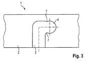
- a carriage 1 is shown for a sliding door.
- the carriage has a cross-sectionally substantially U-shaped carrier profile 2.
- the carrier profile 2 is provided with a base and two free legs projecting substantially at right angles from the base, wherein open longitudinal slots 3 are arranged in each free leg at the end, to each of which a short transverse slot 4 connects at right angles.
- the longitudinal slot 3 thus extends transversely to the longitudinal extension of the carrier profile 2, and the transverse slot 4 extends in the longitudinal extent of the carrier profile. 2
- a roller holder 5 is mounted, which has a plurality of bearings 6 for rollers, not shown.
- the roll holder 5 and the rollers are a preassembled unit.
- the number of provided in the support section 2 longitudinal and transverse slots 3, 4 depends on the number of rollers and the roller holder 5.
- the roller holder 5 has four bearings 6 for rollers. Accordingly, two longitudinal and transverse slots 3, 4 are arranged in the support section 2. Since each sliding door is supported by at least two spaced-apart roller holder 5, a corresponding number and arrangement of longitudinal and transverse slots 3, 4 are provided in the support section 2, which in FIG. 1 but not all are visible.
- a catch is provided, which is formed by a constriction 7 on both sides.
- the pre-assembled unit consisting of roller holder 5 and rollers is fixed to the carrier profile 2 in the manner of a bayonet connection.
- the roller holder 5 is positioned so that the axes of the rollers come to lie in the one-sided open longitudinal slots 3.
- the roll holder 2 is advanced in the direction of the longitudinal slots 3 to her lying near the base of the support section 2 end.
- the roll holder 5 is moved in the direction of the transverse slots 4.
- the axes of the rollers overcome the constriction 7 and engage in the receiving bore formed by the transverse slot 4. Now, each axis is fixed in a receiving bore, and the roll holder is held in position.
Landscapes
- Engineering & Computer Science (AREA)
- Mechanical Engineering (AREA)
- Support Devices For Sliding Doors (AREA)
Abstract

Description
- Die vorliegende Erfindung betrifft einen Laufwagen für eine Schiebetür, wobei der Laufwagen ein Trägerprofil aufweist, in dem zumindest ein Rollenhalter zur Aufnahme von Laufrollen angeordnet ist.
- Bekannte Laufwagen für Schiebetüren weisen ein im Querschnitt im Wesentlichen C-förmiges Trägerprofil auf. In zwei sich gegenüberliegenden Seiten des Trägerprofils sind Aufnahmebohrungen vorgesehen, deren Anzahl von der Anzahl der Laufrollen bestimmt wird. Ein Rollenhalter wird von einem Ende des Trägerprofils soweit in dieses eingeschoben, bis die in dem Rollenhalter angeordneten Lagerstellen für die Achsen der Laufrollen mit den Aufnahmebohrungen im Trägerprofil zur Deckung gelangen. Dann werden die Laufrollen mit ihren Achsen durch die im Trägerprofil angeordneten Aufnahmebohrungen in die Lagerstellen am Laufwagen eingesteckt.
- Dieser bekannte Laufwagen hat den Nachteil, dass die Montage der Laufwagen aufwändig ist und dass keine Baugruppen vorgefertigt werden können. Denn zunächst müssen die Rollenhalter in das Trägerprofil eingeführt und anschließend die Laufrollen an dem Rollenhalter angebracht werden.
- Es ist daher Aufgabe der vorliegenden Erfindung, einen Laufwagen der eingangs genannten Art bereit zu stellen, welcher mit geringem Aufwand montiert und in einzelnen Baugruppen vorgefertigt werden kann.
- Diese Aufgabe wird bei einem Laufwagen für eine Schiebetür, wobei der Laufwagen ein Trägerprofil aufweist, in dem zumindest ein Rollenhalter zur Aufnahme von Laufrollen angeordnet ist, erfindungsgemäß dadurch gelöst, dass der Rollenhalter mittels einer Bajonettverbindung an dem Trägerprofil festlegbar ist.
- Die erfindungsgemäße Ausgestaltung hat den Vorteil, dass der Rollenhalter direkt an seiner Endposition in das Trägerprofil eingesetzt und festgelegt werden kann. Ein vergleichsweise umständliches Einfädeln der Rollenhalter von einem Ende des Trägerprofils kann somit entfallen.
- Die Unteransprüche haben vorteilhafte Weiterbildungen der Erfindung zum Inhalt.
- Gemäß einer vorteilhaften Weiterbildung ist der Rollenhalter zusammen mit den Laufrollen in das Trägerprofil einsetzbar. Somit kann der Rollenhalter unabhängig von der gewünschten Türgröße in großen Mengen in einer einfachen Vorrichtung mit den Laufrollen vormontiert und beispielsweise komplett vom Zulieferer bezogen werden. Dies bringt eine Einsparung nicht nur von Fertigungszeit und Kosten, sondern auch des Montageaufwandes mit sich, da aufgrund der erfindungsgemäßen Ausgestaltung der Rollenhalter komplett montiert in das Trägerprofil eingesetzt werden kann.
- Besonders einfach gestaltet sich das Einsetzen der komplett montierten Rollenhalter, wenn gemäß einer bevorzugten Ausgestaltung das Trägerprofil einen U-förmigen Querschnitt mit einer Basis und zwei von der Basis im Wesentlichen rechtwinklig abstehenden freien Schenkeln aufweist, wobei in jedem freien Schenkel endseitig offene Längsschlitze angeordnet sind, an die sich jeweils rechtwinklig ein kurzer Querschlitz anschließt. Vorteilhafterweise bildet der Querschlitz eine Aufnahmebohrung, welche bei eingesetztem Rollenhalter die Achse einer Laufrolle aufnimmt. Zur Endmontage kann somit der Rollenhalter über die Längsschlitze in das U-förmige Trägerprofil eingeführt und durch seitliches Verschieben in Position gebracht werden. Mittels einer Vorrichtung wird der Rollenhalter in die Endposition gedrückt, wobei die Achsen der Laufrollen in der Aufnahmebohrung liegen.
- Wenn gemäß einer bevorzugten Ausgestaltung am Übergang zwischen dem Längsschlitz und dem Querschlitz eine Raste angeordnet ist, werden die Achsen der Laufrollen in der Aufnahmebohrung verrastet, so dass der Rollenhalter dauerhaft im Trägerprofil festgelegt ist.
- Besonders einfach kann die Raste als beidseitige Einschnürung ausgebildet sein, welche die Aufnahmebohrung zu dem Längsschlitz hin begrenzt.
- Weitere Einzelheiten, Merkmale und Vorteile der Erfindung ergeben sich aus nachfolgender Beschreibung anhand der Zeichnungen. Es zeigen:
- Figur 1
- eine Seitenansicht eines erfindungsgemäßen Trägerprofils,
- Figur 2
- einen Ausschnitt des Trägerprofils nach
Figur 1 in vergrößertem Maßstab, und - Figur 3
- einen in das Trägerprofil einsetzbaren Rollenhalter.
- In den Figuren ist ein Laufwagen 1 für eine Schiebetür dargestellt. Der Laufwagen weist ein im Querschnitt im Wesentlichen U-förmiges Trägerprofil 2 auf.
- Das Trägerprofil 2 ist mit einer Basis und zwei von der Basis im Wesentlichen rechtwinklig abstehenden freien Schenkeln versehen, wobei in jedem freien Schenkel endseitig offene Längsschlitze 3 angeordnet sind, an die sich jeweils rechtwinklig ein kurzer Querschlitz 4 anschließt. Der Längsschlitz 3 verläuft somit quer zur Längserstreckung des Trägerprofils 2, und der Querschlitz 4 verläuft in Längserstreckung des Trägerprofils 2.
- In dem Trägerprofil 2 ist ein Rollenhalter 5 gelagert, der mehrere Lagerstellen 6 für nicht dargestellte Laufrollen aufweist. Der Rollenhalter 5 und die Laufrollen sind eine vormontierte Einheit.
- Die Anzahl der in dem Trägerprofil 2 vorgesehenen Längs- und Querschlitze 3, 4 richtet sich nach der Anzahl der Laufrollen und der Rollenhalter 5. Im dargestellten Ausführungsbeispiel hat der Rollenhalter 5 vier Lagerstellen 6 für Laufrollen. Dementsprechend sind auch in dem Trägerprofil 2 vier Längs- und Querschlitze 3, 4 angeordnet. Da jede Schiebetür zumindest über zwei voneinander beabstandete Rollenhalter 5 getragen wird, sind in dem Trägerprofil 2 auch eine entsprechende Anzahl und Anordnung von Längs- und Querschlitzen 3, 4 vorgesehen, die in
Figur 1 allerdings nicht alle zu sehen sind. - Am Übergang zwischen Längs- und Querschlitz 3, 4 ist eine Raste vorgesehen, die von einer beidseitigen Einschnürung 7 gebildet ist.
- Bei der Montage wird die aus Rollenhalter 5 und Laufrollen bestehende vormontierte Einheit nach Art einer Bajonettverbindung an dem Trägerprofil 2 befestigt. Dazu wird der Rollenhalter 5 so positioniert, dass die Achsen der Laufrollen in die einseitig offenen Längsschlitze 3 zu liegen kommen. Anschließend wird der Rollenhalter 2 in Richtung der Längsschlitze 3 bis an ihr in der Nähe der Basis des Trägerprofils 2 liegendes Ende vorgeschoben. Danach wird der Rollenhalter 5 in Richtung der Querschlitze 4 bewegt. Dabei überwinden die Achsen der Laufrollen die Einschnürung 7 und rasten in die von dem Querschlitz 4 gebildete Aufnahmebohrung ein. Nunmehr ist jede Achse in einer Aufnahmebohrung festgelegt, und der Rollenhalter wird in Position gehalten.
- Die vorhergehende Beschreibung der vorliegenden Erfindung dient nur zu illustrativen Zwecken und nicht zum Zwecke der Beschränkung der Erfindung. Im Rahmen der Erfindung sind verschiedene Änderungen und Modifikationen möglich, ohne den Umfang der Erfindung sowie ihrer Äquivalente zu verlassen.
-
- 1
- Laufwagen
- 2
- Trägerprofil
- 3
- Längsschlitz
- 4
- Querschlitz
- 5
- Rollenhalter
- 6
- Lagerstelle
- 7
- Einschnürung
Claims (6)
- Laufwagen für eine Schiebetür, wobei der Laufwagen ein Trägerprofil aufweist, in dem zumindest ein Rollenhalter zur Aufnahme von Laufrollen angeordnet ist, dadurch gekennzeichnet, dass der Rollenhalter (5) mittels einer Bajonettverbindung an dem Trägerprofil (2) festlegbar ist.
- Laufwagen nach Anspruch 1, dadurch gekennzeichnet, dass der Rollenhalter (5) zusammen mit den Laufrollen in das Trägerprofil (2) einsetzbar ist.
- Laufwagen nach Anspruch 1 oder 2, dadurch gekennzeichnet, dass das Trägerprofil (2) einen U-förmigen Querschnitt mit einer Basis und zwei von der Basis im Wesentlichen rechtwinklig abstehenden freien Schenkeln aufweist und dass in jedem freien Schenkel endseitig offene Längsschlitze (3) angeordnet sind, an die sich jeweils rechtwinklig ein kurzer Querschlitz (4) anschließt.
- Laufwagen nach Anspruch 3, dadurch gekennzeichnet, dass der Querschlitz (4) eine Aufnahmebohrung bildet, welche bei eingesetztem Rollenhalter (5) die Achse einer Laufrolle aufnimmt.
- Laufwagen nach Anspruch 4, dadurch gekennzeichnet, dass am Übergang zwischen dem Längsschlitz (3) und dem Querschlitz (4) eine Raste angeordnet ist.
- Laufwagen nach Anspruch 5, dadurch gekennzeichnet, dass die Raste als beidseitige Einschnürung (7) ausgebildet ist, welche die Aufnahmebohrung zu dem Längsschlitz hin begrenzt.
Applications Claiming Priority (1)
| Application Number | Priority Date | Filing Date | Title |
|---|---|---|---|
| DE201310106056 DE102013106056A1 (de) | 2013-06-11 | 2013-06-11 | Laufwagen für eine Schiebetür |
Publications (2)
| Publication Number | Publication Date |
|---|---|
| EP2813656A1 true EP2813656A1 (de) | 2014-12-17 |
| EP2813656B1 EP2813656B1 (de) | 2016-04-20 |
Family
ID=50685735
Family Applications (1)
| Application Number | Title | Priority Date | Filing Date |
|---|---|---|---|
| EP14001606.4A Not-in-force EP2813656B1 (de) | 2013-06-11 | 2014-05-07 | Laufwagen für eine Schiebetür |
Country Status (2)
| Country | Link |
|---|---|
| EP (1) | EP2813656B1 (de) |
| DE (1) | DE102013106056A1 (de) |
Citations (4)
| Publication number | Priority date | Publication date | Assignee | Title |
|---|---|---|---|---|
| US354808A (en) * | 1886-12-21 | Door-hanger | ||
| US4945605A (en) * | 1988-03-04 | 1990-08-07 | Hawa Ag | Fitting for sliding doors suspended at a runway rail |
| WO2006097965A1 (en) * | 2005-03-16 | 2006-09-21 | Erreti, S.R.L. | Carriage |
| US20100139037A1 (en) * | 2007-08-16 | 2010-06-10 | Dorma Gmbh + Co. Kg | Carriage and Suspension System Utilizing Carriages |
-
2013
- 2013-06-11 DE DE201310106056 patent/DE102013106056A1/de active Pending
-
2014
- 2014-05-07 EP EP14001606.4A patent/EP2813656B1/de not_active Not-in-force
Patent Citations (4)
| Publication number | Priority date | Publication date | Assignee | Title |
|---|---|---|---|---|
| US354808A (en) * | 1886-12-21 | Door-hanger | ||
| US4945605A (en) * | 1988-03-04 | 1990-08-07 | Hawa Ag | Fitting for sliding doors suspended at a runway rail |
| WO2006097965A1 (en) * | 2005-03-16 | 2006-09-21 | Erreti, S.R.L. | Carriage |
| US20100139037A1 (en) * | 2007-08-16 | 2010-06-10 | Dorma Gmbh + Co. Kg | Carriage and Suspension System Utilizing Carriages |
Also Published As
| Publication number | Publication date |
|---|---|
| EP2813656B1 (de) | 2016-04-20 |
| DE102013106056A1 (de) | 2014-12-11 |
Similar Documents
| Publication | Publication Date | Title |
|---|---|---|
| DE102010001146B4 (de) | Kettenschiene für Einziehketten und ein Verfahren zur Herstellung einer Kettenschiene | |
| EP2730734A2 (de) | Bidirektionale Einzugsvorrichtung für eine mittlere Schiebetür | |
| EP2756780B1 (de) | Federleisten-Lager mit Haltezapfen | |
| EP2634822A1 (de) | Vorrichtung zum Lagefixieren eines Lötverbinders auf einer Solarzelle | |
| EP3045638B1 (de) | Schiebe- und Drehflügelsystem | |
| DE102007048499A1 (de) | Verfahren zur Fixierung eines ringförmigen Segmentpaketes mit zylindrischer Außenwand in einem ringförmigen Gehäuse | |
| EP3636844B1 (de) | Trockenbau-tragrahmen für eine schiebetür | |
| AT512899B1 (de) | Verfahren zur Herstellung eines Blechprofils für eine Schubladen-Ausziehführung | |
| EP2634344A1 (de) | Antrieb für einen Flügel eines Fensters oder dergleichen sowie ein Verfahren zur Montage einer Endkappe des Antriebs | |
| EP2009214B1 (de) | Verbindungsstück zum Verbinden zweier Führungsschienen und Führungsschiene | |
| DE4204067A1 (de) | Waelzkoerperfuehrung fuer schubladenfuehrungen | |
| EP2557264A2 (de) | Sektionaltor | |
| EP2813656B1 (de) | Laufwagen für eine Schiebetür | |
| DE102016211059A1 (de) | System zur Befestigung von Kühlermodulen mit mindestens einem Lagerzapfen in einem oberen Abschnitt eines Montageträger eines Kraftfahrzeuges sowie Zwischenelement für die Aufnahme eines Kühlerlagers eines Kühlermoduls | |
| DE102012203244B4 (de) | Antrieb für einen Flügel eines Fensters oder dergleichen sowie ein Verfahren zur Montage des Antriebs | |
| CH706604A2 (de) | Objektband und Anordnung eines Objektbands an einem Tür- oder Fensterblatt und einer Tür- oder Fensterzarge. | |
| AT507675B1 (de) | Befestigungskörper | |
| AT522528B1 (de) | Teleskopierbare Synchronisationsstange | |
| EP3101272A1 (de) | Windgeneratorturbine (varianten) | |
| EP4124709B1 (de) | Führungsprofil für eine auszugssperre, auszugssperre, möbel und verfahren zur bestückung eines führungsprofils | |
| EP2696017B1 (de) | Vorrichtung zum Ausstellen von Fenstern und Türen | |
| DE202013105425U1 (de) | Abstandshalter für eine Gleitführung und Hubsäule | |
| CH699548A2 (de) | Verbindungsanordnung für ein Gliederband. | |
| DE202010002890U1 (de) | Greifvorrichtung | |
| EP2397712A1 (de) | Linearführung mit zwangsgeführtem Käfig |
Legal Events
| Date | Code | Title | Description |
|---|---|---|---|
| 17P | Request for examination filed |
Effective date: 20140507 |
|
| AK | Designated contracting states |
Kind code of ref document: A1 Designated state(s): AL AT BE BG CH CY CZ DE DK EE ES FI FR GB GR HR HU IE IS IT LI LT LU LV MC MK MT NL NO PL PT RO RS SE SI SK SM TR |
|
| AX | Request for extension of the european patent |
Extension state: BA ME |
|
| PUAI | Public reference made under article 153(3) epc to a published international application that has entered the european phase |
Free format text: ORIGINAL CODE: 0009012 |
|
| R17P | Request for examination filed (corrected) |
Effective date: 20150612 |
|
| RBV | Designated contracting states (corrected) |
Designated state(s): AL AT BE BG CH CY CZ DE DK EE ES FI FR GB GR HR HU IE IS IT LI LT LU LV MC MK MT NL NO PL PT RO RS SE SI SK SM TR |
|
| GRAP | Despatch of communication of intention to grant a patent |
Free format text: ORIGINAL CODE: EPIDOSNIGR1 |
|
| INTG | Intention to grant announced |
Effective date: 20151102 |
|
| GRAS | Grant fee paid |
Free format text: ORIGINAL CODE: EPIDOSNIGR3 |
|
| GRAA | (expected) grant |
Free format text: ORIGINAL CODE: 0009210 |
|
| AK | Designated contracting states |
Kind code of ref document: B1 Designated state(s): AL AT BE BG CH CY CZ DE DK EE ES FI FR GB GR HR HU IE IS IT LI LT LU LV MC MK MT NL NO PL PT RO RS SE SI SK SM TR |
|
| REG | Reference to a national code |
Ref country code: GB Ref legal event code: FG4D Free format text: NOT ENGLISH |
|
| REG | Reference to a national code |
Ref country code: CH Ref legal event code: EP |
|
| REG | Reference to a national code |
Ref country code: AT Ref legal event code: REF Ref document number: 792651 Country of ref document: AT Kind code of ref document: T Effective date: 20160515 |
|
| REG | Reference to a national code |
Ref country code: IE Ref legal event code: FG4D Free format text: LANGUAGE OF EP DOCUMENT: GERMAN |
|
| REG | Reference to a national code |
Ref country code: DE Ref legal event code: R096 Ref document number: 502014000630 Country of ref document: DE |
|
| REG | Reference to a national code |
Ref country code: LT Ref legal event code: MG4D |
|
| PG25 | Lapsed in a contracting state [announced via postgrant information from national office to epo] |
Ref country code: BE Free format text: LAPSE BECAUSE OF NON-PAYMENT OF DUE FEES Effective date: 20160531 |
|
| REG | Reference to a national code |
Ref country code: NL Ref legal event code: MP Effective date: 20160420 |
|
| PG25 | Lapsed in a contracting state [announced via postgrant information from national office to epo] |
Ref country code: FI Free format text: LAPSE BECAUSE OF FAILURE TO SUBMIT A TRANSLATION OF THE DESCRIPTION OR TO PAY THE FEE WITHIN THE PRESCRIBED TIME-LIMIT Effective date: 20160420 Ref country code: NO Free format text: LAPSE BECAUSE OF FAILURE TO SUBMIT A TRANSLATION OF THE DESCRIPTION OR TO PAY THE FEE WITHIN THE PRESCRIBED TIME-LIMIT Effective date: 20160720 Ref country code: PL Free format text: LAPSE BECAUSE OF FAILURE TO SUBMIT A TRANSLATION OF THE DESCRIPTION OR TO PAY THE FEE WITHIN THE PRESCRIBED TIME-LIMIT Effective date: 20160420 Ref country code: NL Free format text: LAPSE BECAUSE OF FAILURE TO SUBMIT A TRANSLATION OF THE DESCRIPTION OR TO PAY THE FEE WITHIN THE PRESCRIBED TIME-LIMIT Effective date: 20160420 Ref country code: LT Free format text: LAPSE BECAUSE OF FAILURE TO SUBMIT A TRANSLATION OF THE DESCRIPTION OR TO PAY THE FEE WITHIN THE PRESCRIBED TIME-LIMIT Effective date: 20160420 |
|
| PG25 | Lapsed in a contracting state [announced via postgrant information from national office to epo] |
Ref country code: GR Free format text: LAPSE BECAUSE OF FAILURE TO SUBMIT A TRANSLATION OF THE DESCRIPTION OR TO PAY THE FEE WITHIN THE PRESCRIBED TIME-LIMIT Effective date: 20160721 Ref country code: ES Free format text: LAPSE BECAUSE OF FAILURE TO SUBMIT A TRANSLATION OF THE DESCRIPTION OR TO PAY THE FEE WITHIN THE PRESCRIBED TIME-LIMIT Effective date: 20160420 Ref country code: PT Free format text: LAPSE BECAUSE OF FAILURE TO SUBMIT A TRANSLATION OF THE DESCRIPTION OR TO PAY THE FEE WITHIN THE PRESCRIBED TIME-LIMIT Effective date: 20160822 Ref country code: HR Free format text: LAPSE BECAUSE OF FAILURE TO SUBMIT A TRANSLATION OF THE DESCRIPTION OR TO PAY THE FEE WITHIN THE PRESCRIBED TIME-LIMIT Effective date: 20160420 Ref country code: RS Free format text: LAPSE BECAUSE OF FAILURE TO SUBMIT A TRANSLATION OF THE DESCRIPTION OR TO PAY THE FEE WITHIN THE PRESCRIBED TIME-LIMIT Effective date: 20160420 Ref country code: SE Free format text: LAPSE BECAUSE OF FAILURE TO SUBMIT A TRANSLATION OF THE DESCRIPTION OR TO PAY THE FEE WITHIN THE PRESCRIBED TIME-LIMIT Effective date: 20160420 Ref country code: LV Free format text: LAPSE BECAUSE OF FAILURE TO SUBMIT A TRANSLATION OF THE DESCRIPTION OR TO PAY THE FEE WITHIN THE PRESCRIBED TIME-LIMIT Effective date: 20160420 |
|
| PG25 | Lapsed in a contracting state [announced via postgrant information from national office to epo] |
Ref country code: IT Free format text: LAPSE BECAUSE OF FAILURE TO SUBMIT A TRANSLATION OF THE DESCRIPTION OR TO PAY THE FEE WITHIN THE PRESCRIBED TIME-LIMIT Effective date: 20160420 |
|
| REG | Reference to a national code |
Ref country code: DE Ref legal event code: R097 Ref document number: 502014000630 Country of ref document: DE |
|
| PG25 | Lapsed in a contracting state [announced via postgrant information from national office to epo] |
Ref country code: DK Free format text: LAPSE BECAUSE OF FAILURE TO SUBMIT A TRANSLATION OF THE DESCRIPTION OR TO PAY THE FEE WITHIN THE PRESCRIBED TIME-LIMIT Effective date: 20160420 Ref country code: MC Free format text: LAPSE BECAUSE OF FAILURE TO SUBMIT A TRANSLATION OF THE DESCRIPTION OR TO PAY THE FEE WITHIN THE PRESCRIBED TIME-LIMIT Effective date: 20160420 Ref country code: EE Free format text: LAPSE BECAUSE OF FAILURE TO SUBMIT A TRANSLATION OF THE DESCRIPTION OR TO PAY THE FEE WITHIN THE PRESCRIBED TIME-LIMIT Effective date: 20160420 Ref country code: RO Free format text: LAPSE BECAUSE OF FAILURE TO SUBMIT A TRANSLATION OF THE DESCRIPTION OR TO PAY THE FEE WITHIN THE PRESCRIBED TIME-LIMIT Effective date: 20160420 Ref country code: SK Free format text: LAPSE BECAUSE OF FAILURE TO SUBMIT A TRANSLATION OF THE DESCRIPTION OR TO PAY THE FEE WITHIN THE PRESCRIBED TIME-LIMIT Effective date: 20160420 Ref country code: CZ Free format text: LAPSE BECAUSE OF FAILURE TO SUBMIT A TRANSLATION OF THE DESCRIPTION OR TO PAY THE FEE WITHIN THE PRESCRIBED TIME-LIMIT Effective date: 20160420 |
|
| REG | Reference to a national code |
Ref country code: IE Ref legal event code: MM4A |
|
| PLBE | No opposition filed within time limit |
Free format text: ORIGINAL CODE: 0009261 |
|
| STAA | Information on the status of an ep patent application or granted ep patent |
Free format text: STATUS: NO OPPOSITION FILED WITHIN TIME LIMIT |
|
| PG25 | Lapsed in a contracting state [announced via postgrant information from national office to epo] |
Ref country code: SM Free format text: LAPSE BECAUSE OF FAILURE TO SUBMIT A TRANSLATION OF THE DESCRIPTION OR TO PAY THE FEE WITHIN THE PRESCRIBED TIME-LIMIT Effective date: 20160420 |
|
| REG | Reference to a national code |
Ref country code: FR Ref legal event code: ST Effective date: 20170131 |
|
| 26N | No opposition filed |
Effective date: 20170123 |
|
| PG25 | Lapsed in a contracting state [announced via postgrant information from national office to epo] |
Ref country code: FR Free format text: LAPSE BECAUSE OF NON-PAYMENT OF DUE FEES Effective date: 20160620 |
|
| REG | Reference to a national code |
Ref country code: DE Ref legal event code: R082 Ref document number: 502014000630 Country of ref document: DE Representative=s name: BALDER IP LAW, S.L., ES Ref country code: DE Ref legal event code: R081 Ref document number: 502014000630 Country of ref document: DE Owner name: DORMAKABA DEUTSCHLAND GMBH, DE Free format text: FORMER OWNER: DORMA DEUTSCHLAND GMBH, 58256 ENNEPETAL, DE |
|
| PG25 | Lapsed in a contracting state [announced via postgrant information from national office to epo] |
Ref country code: SI Free format text: LAPSE BECAUSE OF FAILURE TO SUBMIT A TRANSLATION OF THE DESCRIPTION OR TO PAY THE FEE WITHIN THE PRESCRIBED TIME-LIMIT Effective date: 20160420 Ref country code: IE Free format text: LAPSE BECAUSE OF NON-PAYMENT OF DUE FEES Effective date: 20160507 |
|
| REG | Reference to a national code |
Ref country code: CH Ref legal event code: PL |
|
| PG25 | Lapsed in a contracting state [announced via postgrant information from national office to epo] |
Ref country code: CH Free format text: LAPSE BECAUSE OF NON-PAYMENT OF DUE FEES Effective date: 20170531 Ref country code: LI Free format text: LAPSE BECAUSE OF NON-PAYMENT OF DUE FEES Effective date: 20170531 |
|
| PG25 | Lapsed in a contracting state [announced via postgrant information from national office to epo] |
Ref country code: HU Free format text: LAPSE BECAUSE OF FAILURE TO SUBMIT A TRANSLATION OF THE DESCRIPTION OR TO PAY THE FEE WITHIN THE PRESCRIBED TIME-LIMIT; INVALID AB INITIO Effective date: 20140507 |
|
| PG25 | Lapsed in a contracting state [announced via postgrant information from national office to epo] |
Ref country code: LU Free format text: LAPSE BECAUSE OF NON-PAYMENT OF DUE FEES Effective date: 20160507 Ref country code: CY Free format text: LAPSE BECAUSE OF FAILURE TO SUBMIT A TRANSLATION OF THE DESCRIPTION OR TO PAY THE FEE WITHIN THE PRESCRIBED TIME-LIMIT Effective date: 20160420 Ref country code: MK Free format text: LAPSE BECAUSE OF FAILURE TO SUBMIT A TRANSLATION OF THE DESCRIPTION OR TO PAY THE FEE WITHIN THE PRESCRIBED TIME-LIMIT Effective date: 20160420 Ref country code: IS Free format text: LAPSE BECAUSE OF FAILURE TO SUBMIT A TRANSLATION OF THE DESCRIPTION OR TO PAY THE FEE WITHIN THE PRESCRIBED TIME-LIMIT Effective date: 20160420 Ref country code: MT Free format text: LAPSE BECAUSE OF FAILURE TO SUBMIT A TRANSLATION OF THE DESCRIPTION OR TO PAY THE FEE WITHIN THE PRESCRIBED TIME-LIMIT Effective date: 20160420 |
|
| PG25 | Lapsed in a contracting state [announced via postgrant information from national office to epo] |
Ref country code: BG Free format text: LAPSE BECAUSE OF FAILURE TO SUBMIT A TRANSLATION OF THE DESCRIPTION OR TO PAY THE FEE WITHIN THE PRESCRIBED TIME-LIMIT Effective date: 20160420 |
|
| PG25 | Lapsed in a contracting state [announced via postgrant information from national office to epo] |
Ref country code: AL Free format text: LAPSE BECAUSE OF FAILURE TO SUBMIT A TRANSLATION OF THE DESCRIPTION OR TO PAY THE FEE WITHIN THE PRESCRIBED TIME-LIMIT Effective date: 20160420 Ref country code: TR Free format text: LAPSE BECAUSE OF FAILURE TO SUBMIT A TRANSLATION OF THE DESCRIPTION OR TO PAY THE FEE WITHIN THE PRESCRIBED TIME-LIMIT Effective date: 20160420 |
|
| GBPC | Gb: european patent ceased through non-payment of renewal fee |
Effective date: 20180507 |
|
| PG25 | Lapsed in a contracting state [announced via postgrant information from national office to epo] |
Ref country code: GB Free format text: LAPSE BECAUSE OF NON-PAYMENT OF DUE FEES Effective date: 20180507 |
|
| REG | Reference to a national code |
Ref country code: AT Ref legal event code: MM01 Ref document number: 792651 Country of ref document: AT Kind code of ref document: T Effective date: 20190507 |
|
| PG25 | Lapsed in a contracting state [announced via postgrant information from national office to epo] |
Ref country code: AT Free format text: LAPSE BECAUSE OF NON-PAYMENT OF DUE FEES Effective date: 20190507 |
|
| PGFP | Annual fee paid to national office [announced via postgrant information from national office to epo] |
Ref country code: DE Payment date: 20220620 Year of fee payment: 10 |
|
| REG | Reference to a national code |
Ref country code: DE Ref legal event code: R119 Ref document number: 502014000630 Country of ref document: DE |
|
| PG25 | Lapsed in a contracting state [announced via postgrant information from national office to epo] |
Ref country code: DE Free format text: LAPSE BECAUSE OF NON-PAYMENT OF DUE FEES Effective date: 20241203 |