EP2813136A1 - Device for abating vibrations in a cutter bar with alternating motion - Google Patents
Device for abating vibrations in a cutter bar with alternating motion Download PDFInfo
- Publication number
- EP2813136A1 EP2813136A1 EP14170475.9A EP14170475A EP2813136A1 EP 2813136 A1 EP2813136 A1 EP 2813136A1 EP 14170475 A EP14170475 A EP 14170475A EP 2813136 A1 EP2813136 A1 EP 2813136A1
- Authority
- EP
- European Patent Office
- Prior art keywords
- movable blade
- motion
- kinematic
- alternating
- supporting
- Prior art date
- Legal status (The legal status is an assumption and is not a legal conclusion. Google has not performed a legal analysis and makes no representation as to the accuracy of the status listed.)
- Granted
Links
- 230000033001 locomotion Effects 0.000 title claims abstract description 59
- 238000005520 cutting process Methods 0.000 claims abstract description 30
- 230000005540 biological transmission Effects 0.000 claims abstract description 16
- 230000009466 transformation Effects 0.000 claims abstract description 5
- 230000010355 oscillation Effects 0.000 claims 1
- 244000025254 Cannabis sativa Species 0.000 description 7
- 230000000694 effects Effects 0.000 description 6
- 230000007246 mechanism Effects 0.000 description 4
- 241000196324 Embryophyta Species 0.000 description 3
- 230000008878 coupling Effects 0.000 description 3
- 238000010168 coupling process Methods 0.000 description 3
- 238000005859 coupling reaction Methods 0.000 description 3
- 241001494496 Leersia Species 0.000 description 2
- 229910000831 Steel Inorganic materials 0.000 description 2
- 230000001133 acceleration Effects 0.000 description 2
- 230000009471 action Effects 0.000 description 2
- 230000008901 benefit Effects 0.000 description 2
- 239000003795 chemical substances by application Substances 0.000 description 2
- 238000005461 lubrication Methods 0.000 description 2
- 239000000203 mixture Substances 0.000 description 2
- 239000010959 steel Substances 0.000 description 2
- 235000019728 animal nutrition Nutrition 0.000 description 1
- 230000002547 anomalous effect Effects 0.000 description 1
- 238000005266 casting Methods 0.000 description 1
- 230000001427 coherent effect Effects 0.000 description 1
- 210000001520 comb Anatomy 0.000 description 1
- 230000006866 deterioration Effects 0.000 description 1
- 238000009792 diffusion process Methods 0.000 description 1
- 238000007599 discharging Methods 0.000 description 1
- 238000009826 distribution Methods 0.000 description 1
- 230000009977 dual effect Effects 0.000 description 1
- 238000000855 fermentation Methods 0.000 description 1
- 230000004151 fermentation Effects 0.000 description 1
- 238000009413 insulation Methods 0.000 description 1
- 239000000463 material Substances 0.000 description 1
- 238000000034 method Methods 0.000 description 1
- 230000003472 neutralizing effect Effects 0.000 description 1
- 239000000843 powder Substances 0.000 description 1
- 238000004321 preservation Methods 0.000 description 1
- 230000002035 prolonged effect Effects 0.000 description 1
- 210000002105 tongue Anatomy 0.000 description 1
Images






Classifications
-
- A—HUMAN NECESSITIES
- A01—AGRICULTURE; FORESTRY; ANIMAL HUSBANDRY; HUNTING; TRAPPING; FISHING
- A01D—HARVESTING; MOWING
- A01D34/00—Mowers; Mowing apparatus of harvesters
- A01D34/01—Mowers; Mowing apparatus of harvesters characterised by features relating to the type of cutting apparatus
- A01D34/02—Mowers; Mowing apparatus of harvesters characterised by features relating to the type of cutting apparatus having reciprocating cutters
- A01D34/30—Driving mechanisms for the cutters
- A01D34/305—Balancing
-
- A—HUMAN NECESSITIES
- A01—AGRICULTURE; FORESTRY; ANIMAL HUSBANDRY; HUNTING; TRAPPING; FISHING
- A01D—HARVESTING; MOWING
- A01D34/00—Mowers; Mowing apparatus of harvesters
- A01D34/01—Mowers; Mowing apparatus of harvesters characterised by features relating to the type of cutting apparatus
- A01D34/02—Mowers; Mowing apparatus of harvesters characterised by features relating to the type of cutting apparatus having reciprocating cutters
- A01D34/08—Mowers; Mowing apparatus of harvesters characterised by features relating to the type of cutting apparatus having reciprocating cutters hand-guided by a walking operator
Definitions
- the present invention relates to a device for abating the vibrations of a cutter bar with alternating motion.
- Cutting devices of this type are in fact assembled on most mowers adopted by the user on foot for cutting grass, fodder and plants in general in both the professional field and as a hobby.
- Figures 1 to 5 show the state of the art for these devices and their application in a mower 11.
- current cutter bars 12 are composed of a structural supporting part 13, known in the field as “guide bar”, normally made of steel.
- This structural part 13 has a width equal to that to be cut and is made integral with the structure of the mower by means of a mechanical supporting and transmission group 20.
- a certain number of cutting elements or teeth 15, having a pointed triangular form, are rigidly fixed to this supporting part or guide bar 13, for example by means of bolts 14, and contribute to forming the so-called comb.
- the sharp edges can be equipped with prominent teeth 16 to accentuate the withholding of blades of grass during the cutting.
- a blade 17 rests on the above-mentioned plane thus defined, which is held in close contact with it by a series of rigid or elastic retainers called blade-holders 18.
- the blade 17 is normally made of steel and also has a certain number of cutting elements 19, or bladelets, having a triangular or trapezoidal shape with sharp cutting sides ( figure 4 ).
- a mechanical supporting and transmission group 20 ( figure 6 ), also normally moved by a motor 41 ( figure 1 ), generally endothermic, of the mower, contemporaneously carries the blade 17 and imparts an alternating movement with an appropriate frequency and amplitude to the same blade.
- Said mechanical supporting and transmission group 20 is rigidly connected to the guide bar 13 and connected to the blade 17 in the centre or at the sides with an articulated device 42 compatible with the transmission of the movement to be effected. In this way, the cutting bladelets 19 of the blade 17 pass alternatingly in correspondence with the spaces defined by the cutting elements 15 of the comb and effect the cutting with a procedure similar to that of scissors.
- This cutting device and relative supporting and transmission group work extremely well, but are not without problems.
- the blade 17 must be sufficiently robust as to be able to effect the cutting and resist any possible occasional and unexpected impact and stress. It must also be relatively insensitive to wear so as to ensure a sufficient duration and satisfactory preservation of the cutting edge with time.
- the cutter bar 12, and consequently the blade 17, must have a width which is coherent with the weight, power and preferential use of the mower 11 on which they must operate.
- Most professional or semi-professional mowers currently operate with bars having a weight ranging form 1 to 2 meters.
- the blade 17 is connected to the supporting and transmission group 20 of the motion which moves it by means of a robust and adequately structured mechanical connection.
- blades 17 having a significant mass, for example around 3 Kg per meter of width.
- a crucial parameter for obtaining this result is the relative velocity with which the cutting edge of the bladelets impacts the blades of grass forcing them against the cutting elements of the comb. Within certain limits, the greater this velocity, the better the cutting will be.
- the blade 17 must therefore move with an alternating motion with a high frequency, often in the order of 1,000 complete cycles per minute or even higher.
- the run For physical reasons linked to both the blade itself and to the vegetation to be cut, the run must be at least a few centimetres, typically reaching values ranging from 5 to 10 centimetres.
- Mowers which use these cutter bars are typically equipped with only two wheels 43 at the end of the same axis, having the cutter bar 12 at one end and the handlebars 44 at the opposite end.
- the alternating force of inertia produces a momentum that the very structure of the machine amplifies and transforms into vibrations having a high intensity.
- a general objective of the present invention is to solve the above-mentioned drawbacks of the known art in cutter bars, in an extremely simple, economical and particularly functional manner.
- a further objective of the present invention is to provide a device which is capable of eliminating or minimizing the inertial forces in a cutter bar of a mower during the operative movement of the cutting blade.
- Another objective of the present invention is to provide a device for abating the vibrations in a cutter bar with alternating motion which maintains an optimum cutting function.
- a mower 11 carries the cutter bar 12 by means of a supporting and transmission group of the motion 20.
- the blade 17 is ultimately connected to the transmission group 20 of the motion by means of a robust and adequately structured mechanical connection.
- the supporting and transmission group of the motion 20 of the blade 17 of the cutter bar 12 is constrained to the front part of the mower 11 by means of a support 45 positioned in correspondence with a power takeoff 46 produced by means of a rotating shaft.
- the support 45 is in fact hollow, it is coupled with a carter 40 for the whole device, and a horizontal shaft 47 supported by bearings 21 and 22, passes through it.
- the shaft 47 carries a joint 23 at its free end towards the interior, whereby it is rotated by the power takeoff 46 of the mower 11.
- the shaft 47 comprises, on one of its flanged ends 48, an eccentric pin 24 which is engaged in a hole 53 of a cylindrical barrel cursor 25.
- the cylindrical barrel cursor 25 is free to slide vertically in a cylindrical seat 49 of an internal crank 26.
- the internal crank 26 is engaged, through a grooved coupling 27, with a lower end of a vertical shaft 28 supported by bearings 29 and 30 inside the carter 40, thus being able to oscillate around the shaft 28.
- Said vertical shaft 28 is engaged at the upper end, through a second grooved coupling 31, with a first end of an outer crank 32, which can therefore also oscillate around the shaft 28 like the internal crank 26.
- the outer crank 32 carries a hinged roll 33, whereby it is connected to the blade 17 and is engaged in an articulated device 42 constrained above the same blade ( figures 6-10 ).
- a pass-through hole 36 whose upper end has an enlarged diameter in which there is an additional pin 34 which acts as a movable fulcrum.
- the additional pin 34 supports, by means of a pair of bearings 35, a balancing mass 37 which is free to oscillate.
- Said balancing mass 37 has an extension 38 at the rear, which is inserted in a cylindrical barrel cursor 39, which acts as a fixed fulcrum.
- the cylindrical barrel cursor 39 is free to slide vertically and rotate in a cylindrical seat 51 situated in the carter 40.
- This coupling allows both angular and axial movements between the parts and creates a further kinematic system for the alternating movement of the balancing mass 37 in a direction opposite to that of the movable blade 17, wherein this latter kinematic system is associated with and moved by the above-mentioned first kinematic system.
- the form of the balancing mass 37 is such that the barycentre is as close as possible to the blade 17 of the cutter bar 12, indicated for example in 52.
- the whole mechanism of the device is enclosed inside the casting of the supporting carter 40 which does not create any encumbrance.
- a possible encumbrance would in fact disturb the cutting and discharging of the grass, and the presence of this carter 40 maintains an indispensable lubrication and preserves the components from the action of contaminating agents.
- the position of the balancing mass 37 and the relative movement must satisfy some particular conditions.
- the mass 37 must be positioned as close as possible to the blade 17 so that the residual torque is minimum, due to the fact that the lines of action of the two forces of inertia are not perfecting coinciding.
- the movement of the balancing mass 37 must be as straight as possible, so as to generate a force of inertia as parallel as possible to the force of inertia due to the blade 17.
- the product of the mass for the run of the balancing mass must be as close as possible to the value of the same product between the mass and run of the blade.
- the movement of the barycentre is advantageously not circular as it derives from the composition of two opposed circular movements and this directs the trajectory towards a straight movement that would be optimum without there being any further complications in the mechanism.
- the motion of the barycentre 52 in figures 11 to 13 derives from the composition of two opposite arcs of circumference.
- Figure 14 shows the path of the trajectories as referred to above. Said figure 14 provides a clearer illustration of the fixed fulcrum 39 of the oscillating mass 37 and the movable fulcrum 34 which entrains the same oscillating mass 37.
- C indicates a trajectory with an arc of circumference of the same movable fulcrum 34.
- the barycentre 52 of the oscillating mass 37 would move around a line E (indicated by a dotted line) with a curved trajectory, if it were to simply oscillate around the fixed fulcrum 39.
- the trajectory of the barycentre 52 is indicated with the continuous line F created by the presence of the second kinematic system which is extremely close to an ideal straight trajectory indicated with G.
- the mass 37 oscillates around the fixed fulcrum 39 moved by the movable fulcrum 34 positioned on the internal crank 26.
- the distance between the two fulcra is much less than that between the fulcrum 39 and the barycentre 52 and creates a lever effect.
- the movement of the barycentre 52 is considerably amplified, as it can effect a significant increase in accelerations and consequently in the balancing inertial effect, even without using excessively high and encumbering masses 37.
- a second balancing mass 54 which can be positioned on the first internal crank 26 which contributes even more to eliminating the vibrations that can arise due to the motion inversions, increasing the benefits of the balancing mass 37 mentioned above positioned on the additional kinematic system.
- the present invention has identified a device which neutralizes the force which creates the vibratory motion, as it arises.
- the effect has therefore been obtained by using a mass having an appropriate value, which is moved in an alternating motion in counter-phase against the blade with an amplitude calculated so that most of the alternating forces of inertia are cancelled.
- the vibratory level is thus reduced on the handlebars, structures and driving controls with a marked increase in the ergonomics and ease of use. As the vibratory forces are cancelled at the source, the vibrations are reduced in the whole machine, protecting the mechanical components from stress which can jeopardize their reliability.
- the supporting functions of the bar, blade drive and movement of the balancing masses are advantageously integrated and contained in a single carter 40 having an adequate form with all the internal components in an oil bath.
- the resulting mechanism is suitable for professional use as it is airtight, insensitive to powder and contaminating agents typical of the environment of use.
- the constant lubrication improves the reliability of the mechanism and dissipation of the heat generated during functioning.
- the annulment at the source of the phenomenon makes the device suitable for all machine configurations which can have different mass distributions.
- the device itself must only be dimensioned in relation to the cutter bar that it must activate and can be designed for being adapted to a vast range of widths of the bar and consequently blade mass.
Landscapes
- Life Sciences & Earth Sciences (AREA)
- Environmental Sciences (AREA)
- Harvester Elements (AREA)
- Automatic Cycles, And Cycles In General (AREA)
Abstract
Description
- The present invention relates to a device for abating the vibrations of a cutter bar with alternating motion.
- At present, in the field of cutting devices which use cutter bars with an alternating motion, in particular so-called mowers, there are problems connected with the vibrations.
- Cutting devices of this type are in fact assembled on most mowers adopted by the user on foot for cutting grass, fodder and plants in general in both the professional field and as a hobby.
-
Figures 1 to 5 show the state of the art for these devices and their application in amower 11. In particular,current cutter bars 12 are composed of a structural supportingpart 13, known in the field as "guide bar", normally made of steel. Thisstructural part 13 has a width equal to that to be cut and is made integral with the structure of the mower by means of a mechanical supporting andtransmission group 20. - A certain number of cutting elements or
teeth 15, having a pointed triangular form, are rigidly fixed to this supporting part orguide bar 13, for example by means ofbolts 14, and contribute to forming the so-called comb. - The upper surface of these
cutting elements 15, when constrained to thestructural part 13, forms a plane which is composed of a certain number of teeth, having a triangular form, whose sides consist of lateral sharp edges. The sharp edges can be equipped withprominent teeth 16 to accentuate the withholding of blades of grass during the cutting. There can also be opposing tongues or other expedients (not shown) for improving the effectiveness of the cutting. - A
blade 17 rests on the above-mentioned plane thus defined, which is held in close contact with it by a series of rigid or elastic retainers called blade-holders 18. - The
blade 17 is normally made of steel and also has a certain number ofcutting elements 19, or bladelets, having a triangular or trapezoidal shape with sharp cutting sides (figure 4 ). - The cutting of the grass is effected through two movements: the
cutter bar 12 moves forward in the grass pushed by the movement of themower 11 with which it is integral and in this way, the blades of grass to be cut penetrate the spaces of the combs. A mechanical supporting and transmission group 20 (figure 6 ), also normally moved by a motor 41 (figure 1 ), generally endothermic, of the mower, contemporaneously carries theblade 17 and imparts an alternating movement with an appropriate frequency and amplitude to the same blade. Said mechanical supporting andtransmission group 20 is rigidly connected to theguide bar 13 and connected to theblade 17 in the centre or at the sides with an articulateddevice 42 compatible with the transmission of the movement to be effected. In this way, thecutting bladelets 19 of theblade 17 pass alternatingly in correspondence with the spaces defined by thecutting elements 15 of the comb and effect the cutting with a procedure similar to that of scissors. - This cutting device and relative supporting and transmission group work extremely well, but are not without problems.
- In order for the
cutter bar 12 to be effective and functional, various indispensable physical characteristics of theblade 17, which is the active component of the tool, must in fact be taken into account. - The
blade 17 must be sufficiently robust as to be able to effect the cutting and resist any possible occasional and unexpected impact and stress. It must also be relatively insensitive to wear so as to ensure a sufficient duration and satisfactory preservation of the cutting edge with time. - Finally, the
cutter bar 12, and consequently theblade 17, must have a width which is coherent with the weight, power and preferential use of themower 11 on which they must operate. Most professional or semi-professional mowers currently operate with bars having a weight ranging form 1 to 2 meters. - Finally, the
blade 17 is connected to the supporting andtransmission group 20 of the motion which moves it by means of a robust and adequately structured mechanical connection. - These requisites generate
blades 17 having a significant mass, for example around 3 Kg per meter of width. - It is also essential, especially for professional use, for the cutting of plant blades to be sharp and precise. The plants would otherwise be damaged, reducing or jeopardizing the possibility of obtaining subsequent cuttings.
- If the machine is used for cutting fodder for animal nutrition, an imprecise cutting will deteriorate the quality of the product, as it would produce anomalous fermentations reducing its quality and value.
- A crucial parameter for obtaining this result is the relative velocity with which the cutting edge of the bladelets impacts the blades of grass forcing them against the cutting elements of the comb. Within certain limits, the greater this velocity, the better the cutting will be. The
blade 17 must therefore move with an alternating motion with a high frequency, often in the order of 1,000 complete cycles per minute or even higher. - For physical reasons linked to both the blade itself and to the vegetation to be cut, the run must be at least a few centimetres, typically reaching values ranging from 5 to 10 centimetres.
- The entity of the movement, together with the frequency of the strokes and mass of the blade, generates significant accelerations and therefore high inertial forces.
- Mowers which use these cutter bars are typically equipped with only two
wheels 43 at the end of the same axis, having thecutter bar 12 at one end and thehandlebars 44 at the opposite end. The alternating force of inertia produces a momentum that the very structure of the machine amplifies and transforms into vibrations having a high intensity. - These vibrations are naturally harmful for the duration and mechanical reliability, but above all cause a marked deterioration in the ease of use, they damage the ergonomics, tiring the user, thus requiring more frequent and prolonged stops.
- Strategies have been studied in various phases for preventing the propagation of these vibrations, which substantially consist in either insulating the sensitive parts or trying to neutralize the vibrations at their source.
- It has so far been observed that insulating the remaining parts of the mower is particularly problematical as these vibrations are significant from an energy point of view and have a frequency which is such as to require excessively extensive movements of the insulating devices. These movements can often be incompatible with the use of the machine or simply cannot be obtained with mechanical devices having a reasonable cost. They would in any case continue to disturb the remaining mechanical parts rigidly connected to the mower.
- Until now, so-called double-movement cutter bars have been developed, in which both the blade and the comb move with an alternating opposed motion. In this type of bar, the inertial forces are more balanced and the consequent vibrations reduced, even if not completely eliminated.
- A general objective of the present invention is to solve the above-mentioned drawbacks of the known art in cutter bars, in an extremely simple, economical and particularly functional manner.
- A further objective of the present invention is to provide a device which is capable of eliminating or minimizing the inertial forces in a cutter bar of a mower during the operative movement of the cutting blade.
- Another objective of the present invention is to provide a device for abating the vibrations in a cutter bar with alternating motion which maintains an optimum cutting function.
- In view of the above objectives, according to the present invention, a device for abating the vibrations in a cutter bar with alternating motion, has been conceived, having the characteristics specified in the enclosed claims.
- The structural and functional characteristics of the present invention and its advantages with respect to the known art will appear more evident from the following description, referring to the enclosed drawings, which, inter alia, show an embodiment of a device for abating the vibrations in a cutter bar with alternating motion produced according to the invention.
- In the drawings:
-
figures 1 ,2 ,3 ,4 and 5 are schematic views which show a mower, a cutter bar and an enlarged detail thereof, a cutting blade and a detail thereof, produced according to the known art; -
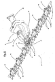
figure 6 is a schematic perspective view of a cutter bar provided with a supporting and transmission group equipped with a device according to the present invention; -
figure 7 is an enlarged, partially sectional, perspective view of the device according to the invention shown infigure 6 ; -
figure 8 is a perspective view of part of the device offigure 7 ; -
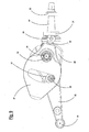
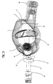
figures 9 and10 are plan views from below and above of the device offigure 8 ; -
figures 11, 12 and 13 are schematic views from below of operating phases of the previous device; -
figure 14 shows the route of trajectories of the elements shown infigures 9 and10 . - As previously specified, a
mower 11 carries thecutter bar 12 by means of a supporting and transmission group of themotion 20. - The
blade 17 is ultimately connected to thetransmission group 20 of the motion by means of a robust and adequately structured mechanical connection. - More specifically, as shown in
figures 6 and7 , the supporting and transmission group of themotion 20 of theblade 17 of thecutter bar 12 is constrained to the front part of themower 11 by means of asupport 45 positioned in correspondence with apower takeoff 46 produced by means of a rotating shaft. - The
support 45 is in fact hollow, it is coupled with acarter 40 for the whole device, and ahorizontal shaft 47 supported bybearings shaft 47 carries a joint 23 at its free end towards the interior, whereby it is rotated by thepower takeoff 46 of themower 11. - At the opposite end, the
shaft 47 comprises, on one of itsflanged ends 48, aneccentric pin 24 which is engaged in a hole 53 of acylindrical barrel cursor 25. Thecylindrical barrel cursor 25 is free to slide vertically in acylindrical seat 49 of aninternal crank 26. - The
internal crank 26 is engaged, through agrooved coupling 27, with a lower end of avertical shaft 28 supported bybearings carter 40, thus being able to oscillate around theshaft 28. Saidvertical shaft 28 is engaged at the upper end, through a secondgrooved coupling 31, with a first end of anouter crank 32, which can therefore also oscillate around theshaft 28 like theinternal crank 26. - At one of its second opposite ends, the
outer crank 32 carries ahinged roll 33, whereby it is connected to theblade 17 and is engaged in an articulateddevice 42 constrained above the same blade (figures 6-10 ). - This creates a transformation kinematic system of a rotating movement from the
power takeoff 46 to a motion of themovable blade 17 which is flat with an alternating movement, in a direction transversal to the advance direction of themower 11 and perpendicular to an axis of thepower takeoff 46. - Furthermore, according to the present invention, on the internal crank 26, there is a pass-through
hole 36, whose upper end has an enlarged diameter in which there is anadditional pin 34 which acts as a movable fulcrum. Theadditional pin 34 supports, by means of a pair ofbearings 35, a balancingmass 37 which is free to oscillate. Said balancingmass 37 has anextension 38 at the rear, which is inserted in acylindrical barrel cursor 39, which acts as a fixed fulcrum. Thecylindrical barrel cursor 39 is free to slide vertically and rotate in acylindrical seat 51 situated in thecarter 40. This coupling allows both angular and axial movements between the parts and creates a further kinematic system for the alternating movement of the balancingmass 37 in a direction opposite to that of themovable blade 17, wherein this latter kinematic system is associated with and moved by the above-mentioned first kinematic system. - In particular, the form of the balancing
mass 37 is such that the barycentre is as close as possible to theblade 17 of thecutter bar 12, indicated for example in 52. - As already mentioned, the whole mechanism of the device is enclosed inside the casting of the supporting
carter 40 which does not create any encumbrance. A possible encumbrance would in fact disturb the cutting and discharging of the grass, and the presence of thiscarter 40 maintains an indispensable lubrication and preserves the components from the action of contaminating agents. - To ensure the effectiveness of the present invention, the position of the balancing
mass 37 and the relative movement must satisfy some particular conditions. - The
mass 37 must be positioned as close as possible to theblade 17 so that the residual torque is minimum, due to the fact that the lines of action of the two forces of inertia are not perfecting coinciding. - The movement of the balancing
mass 37 must be as straight as possible, so as to generate a force of inertia as parallel as possible to the force of inertia due to theblade 17. - The product of the mass for the run of the balancing mass must be as close as possible to the value of the same product between the mass and run of the blade.
- These requirements are in contrast with the necessity of allowing the cut grass to be discharged immediately behind the
blade 17. If an excessively voluminous mass were positioned close to theblade 17, the cut grass could not be discharged and would accumulate very rapidly, creating an obstacle for the cutting. - The movement of the barycentre is advantageously not circular as it derives from the composition of two opposed circular movements and this directs the trajectory towards a straight movement that would be optimum without there being any further complications in the mechanism. The motion of the
barycentre 52 infigures 11 to 13 derives from the composition of two opposite arcs of circumference. - The analogous movement of the
additional pin 34, which acts as a movable fulcrum with an opposite concavity, superimposes the circular trajectory described, of theoscillating mass 37 around the fixed fulcrum defined by thecylindrical barrel cursor 39. In this way, the resulting trajectory is more similar to the straight trajectory of the blade. -
Figure 14 shows the path of the trajectories as referred to above. Saidfigure 14 provides a clearer illustration of the fixedfulcrum 39 of theoscillating mass 37 and themovable fulcrum 34 which entrains the same oscillatingmass 37. - C indicates a trajectory with an arc of circumference of the same
movable fulcrum 34. - The
barycentre 52 of theoscillating mass 37 would move around a line E (indicated by a dotted line) with a curved trajectory, if it were to simply oscillate around the fixedfulcrum 39. - Contrarily and advantageously, on the other hand, according to the present invention, the trajectory of the
barycentre 52 is indicated with the continuous line F created by the presence of the second kinematic system which is extremely close to an ideal straight trajectory indicated with G. - It can be clearly seen that, only by composing the movements, an oscillating
mass 37 is obtained, which moves constrained to the pins with an almost straight motion. - This increases its efficacy as the
blade 17 moves with an absolutely straight motion. - In order to allow this dual movement, the
rear extension 38 of the balancingmass 37 and the presence of thecylindrical barrel cursor 39, free to slide vertically in thecylindrical seat 51 situated in thecarter 40, allow to some extent both the rotation and translation of the balancingmass 37, which is all clearly illustrated in the functioning phases offigures 11 to 13 . - The
mass 37 oscillates around the fixedfulcrum 39 moved by themovable fulcrum 34 positioned on theinternal crank 26. The distance between the two fulcra is much less than that between the fulcrum 39 and the barycentre 52 and creates a lever effect. In this way, the movement of thebarycentre 52 is considerably amplified, as it can effect a significant increase in accelerations and consequently in the balancing inertial effect, even without using excessively high and encumberingmasses 37. - In a preferred optional embodiment, there can also be the presence of a
second balancing mass 54 which can be positioned on the first internal crank 26 which contributes even more to eliminating the vibrations that can arise due to the motion inversions, increasing the benefits of the balancingmass 37 mentioned above positioned on the additional kinematic system. - It can therefore be observed how, according to the invention, the strategy of neutralizing the vibrations from the source has been created for preventing the diffusion of the same vibrations.
- This avoids having to insulate some of the parts of the mower, which is particularly problematical as these vibrations are significant from the point of view of energy, but with a frequency which requires excessively extensive movements of the insulation devices. These movements can often be incompatible with the use of the machine or simply cannot be obtained with mechanical devices having an acceptable cost. They would in any case continue to disturb the remaining mechanical parts rigidly connected to the machine itself.
- The present invention has identified a device which neutralizes the force which creates the vibratory motion, as it arises. The effect has therefore been obtained by using a mass having an appropriate value, which is moved in an alternating motion in counter-phase against the blade with an amplitude calculated so that most of the alternating forces of inertia are cancelled.
- The vibratory level is thus reduced on the handlebars, structures and driving controls with a marked increase in the ergonomics and ease of use. As the vibratory forces are cancelled at the source, the vibrations are reduced in the whole machine, protecting the mechanical components from stress which can jeopardize their reliability.
- The supporting functions of the bar, blade drive and movement of the balancing masses are advantageously integrated and contained in a
single carter 40 having an adequate form with all the internal components in an oil bath. The resulting mechanism is suitable for professional use as it is airtight, insensitive to powder and contaminating agents typical of the environment of use. The constant lubrication improves the reliability of the mechanism and dissipation of the heat generated during functioning. - In addition, the annulment at the source of the phenomenon makes the device suitable for all machine configurations which can have different mass distributions. The device itself must only be dimensioned in relation to the cutter bar that it must activate and can be designed for being adapted to a vast range of widths of the bar and consequently blade mass.
- The objective indicated in the preamble of the description has therefore been achieved.
- The forms of the structure for the embodiment of a device of the invention, as also the materials and assembly modes, can obviously differ from those shown for purely illustrative and non-limiting purposes in the drawings.
- The protection scope of the invention is therefore delimited by the enclosed claims.
Claims (7)
- A device for abating vibrations in a cutter bar (12) with alternating motion coupled with a supporting and transmission group (20) connected to a power takeoff (46) of the mower (11), said supporting and transmission group (20) comprising a kinematic transformation system of a rotary motion coming from said power takeoff (46) into a motion of the movable blade (17) which is flat with an alternating movement, in a transversal direction with respect to the advance direction of the mower and perpendicular to an axis of the power takeoff (46), wherein said movable blade is kept in engagement on cutting elements (15) constrained to said supporting and transmission group (20), characterized in that a further second kinematic system is associated with said first kinematic transformation system of the rotary motion into a flat motion with an alternating movement of said movable blade (17), for the alternating backwards and forwards movement of a balancing mass (37) in an opposite direction to that of said movable blade (17), wherein said second further kinematic system is moved by said first kinematic system.
- The device according to claim 1, characterized in that both said first and second kinematic systems are contained in a single carter (40).
- The device according to claim 1 or 2, characterized in that said power takeoff (46) is connected by means of an eccentric pin (24) to a cylindrical seat (49) of a crank (26, 32) of which a free end is rotatingly connected (33, 42) to said movable blade (17), said oscillating mass (37) of said second kinematic system being hinged (in 34) in an intermediate position of said crank (26, 32) and constrained at one of its ends around a fixed fulcrum (39) of a containment carter (40).
- The device according to claim 3, characterized in that said fixed fulcrum comprises a cylindrical barrel cursor (39) which is free to slide vertically and rotate in a cylindrical seat (51) situated in said carter (40).
- The device according to claim 3, characterized in that said crank comprises an internal crank (26), which is engaged with a shaft (28) supported (in 29 and 30) inside said carter (40), and an outer crank (32) constrained on one side to said shaft (28) and on the other side connected by means of a roll (33) to an articulated device (42) constrained above said movable blade (17).
- The device according to one or more of the previous claims, characterized in that said balancing mass (37) has a form which is such as to have a barycentre (52) as close as possible to said movable blade (17) of the cutter bar (12).
- The device according to one or more of the previous claims, characterized in that a barycentre (52) of said balancing mass (37) during its oscillation follows an essentially straight trajectory.
Applications Claiming Priority (1)
| Application Number | Priority Date | Filing Date | Title |
|---|---|---|---|
| IT000969A ITMI20130969A1 (en) | 2013-06-13 | 2013-06-13 | DEVICE FOR FILLING VIBRATIONS IN AN ALTERNATED MOTORCYCLE BAR |
Publications (2)
| Publication Number | Publication Date |
|---|---|
| EP2813136A1 true EP2813136A1 (en) | 2014-12-17 |
| EP2813136B1 EP2813136B1 (en) | 2018-03-21 |
Family
ID=49000537
Family Applications (1)
| Application Number | Title | Priority Date | Filing Date |
|---|---|---|---|
| EP14170475.9A Not-in-force EP2813136B1 (en) | 2013-06-13 | 2014-05-29 | Device for abating vibrations in a cutter bar with alternating motion |
Country Status (3)
| Country | Link |
|---|---|
| EP (1) | EP2813136B1 (en) |
| CN (1) | CN104221576B (en) |
| IT (1) | ITMI20130969A1 (en) |
Families Citing this family (9)
| Publication number | Priority date | Publication date | Assignee | Title |
|---|---|---|---|---|
| CN104996063A (en) * | 2015-07-17 | 2015-10-28 | 重庆嘉木机械有限公司 | Grass mowing-mini-tilling dual-purpose machine scissors opening-closing driving structure |
| CN105052354A (en) * | 2015-07-17 | 2015-11-18 | 重庆嘉木机械有限公司 | Mechanism for driving scissors of agricultural multi-functional machine to open and close |
| CN106068893B (en) * | 2016-08-26 | 2018-03-02 | 浙江乐客来机械有限公司 | A kind of thick cutting mill device of row |
| CN106171256B (en) * | 2016-08-26 | 2018-03-13 | 浙江乐客来机械有限公司 | The thick cutting mill device of row |
| CN106171251B (en) * | 2016-08-26 | 2018-03-30 | 浙江乐客来机械有限公司 | A kind of thick cutting mill of row |
| CN106105544B (en) * | 2016-08-26 | 2018-03-02 | 浙江乐客来机械有限公司 | Thick cutting mill device |
| CN106385940A (en) * | 2016-11-04 | 2017-02-15 | 成都森钰泓绿化工程有限公司 | Handheld row type lawn mower |
| CN106385941A (en) * | 2016-11-04 | 2017-02-15 | 成都森钰泓绿化工程有限公司 | Hand-push row-type trimmer for trimming lawn for greening |
| CN117337999A (en) * | 2023-08-15 | 2024-01-05 | 潍坊市农业科学院(山东省农业科学院潍坊市分院) | Ginger juice pressing equipment and pressing method |
Citations (5)
| Publication number | Priority date | Publication date | Assignee | Title |
|---|---|---|---|---|
| US2769297A (en) * | 1953-08-13 | 1956-11-06 | Int Harvester Co | Balanced mower |
| US2808696A (en) * | 1954-10-26 | 1957-10-08 | Int Harvester Co | Counterbalanced drive mechanism for harvester sickles |
| US2819618A (en) * | 1953-05-04 | 1958-01-14 | Slusher Frank | Counterbalancing apparatus for reciprocating slide |
| US6314707B1 (en) * | 2000-01-06 | 2001-11-13 | Cyril A. Ryan | Balanced reciprocating, brush cutting, mower attachment |
| US8011272B1 (en) * | 2010-04-28 | 2011-09-06 | Cnh America Llc | Dual flywheel axially compact epicyclical drive |
Family Cites Families (5)
| Publication number | Priority date | Publication date | Assignee | Title |
|---|---|---|---|---|
| GB1447441A (en) * | 1974-01-02 | 1976-08-25 | Heath H C | Counterbalanced twin knife mower |
| IT1158620B (en) * | 1980-02-20 | 1987-02-18 | Ferrari Fernando Spa Off Mec | CONTROL UNIT FOR MOWING BARS IN GENERAL |
| AT403336B (en) * | 1996-07-18 | 1998-01-26 | Bauer & Co Gmbh Reform Werke | MANUAL, SELF-DRIVING WORKING MACHINE |
| CN2676593Y (en) * | 2003-10-24 | 2005-02-09 | 李晋全 | Semi-seated threshing roller combine |
| US7121074B1 (en) * | 2005-05-31 | 2006-10-17 | Acco Corporation | Balanced epicyclic sickle drive |
-
2013
- 2013-06-13 IT IT000969A patent/ITMI20130969A1/en unknown
-
2014
- 2014-05-29 EP EP14170475.9A patent/EP2813136B1/en not_active Not-in-force
- 2014-06-13 CN CN201410419053.7A patent/CN104221576B/en not_active Expired - Fee Related
Patent Citations (5)
| Publication number | Priority date | Publication date | Assignee | Title |
|---|---|---|---|---|
| US2819618A (en) * | 1953-05-04 | 1958-01-14 | Slusher Frank | Counterbalancing apparatus for reciprocating slide |
| US2769297A (en) * | 1953-08-13 | 1956-11-06 | Int Harvester Co | Balanced mower |
| US2808696A (en) * | 1954-10-26 | 1957-10-08 | Int Harvester Co | Counterbalanced drive mechanism for harvester sickles |
| US6314707B1 (en) * | 2000-01-06 | 2001-11-13 | Cyril A. Ryan | Balanced reciprocating, brush cutting, mower attachment |
| US8011272B1 (en) * | 2010-04-28 | 2011-09-06 | Cnh America Llc | Dual flywheel axially compact epicyclical drive |
Also Published As
| Publication number | Publication date |
|---|---|
| EP2813136B1 (en) | 2018-03-21 |
| CN104221576A (en) | 2014-12-24 |
| CN104221576B (en) | 2016-10-26 |
| ITMI20130969A1 (en) | 2014-12-14 |
Similar Documents
| Publication | Publication Date | Title |
|---|---|---|
| EP2813136B1 (en) | Device for abating vibrations in a cutter bar with alternating motion | |
| JP7610453B2 (en) | Garden trimmer | |
| EP3563656A1 (en) | Cutter blade and lawn mower | |
| JP6310646B2 (en) | Brush cutter blade | |
| US11490565B2 (en) | Cutter blade and mower | |
| US6314707B1 (en) | Balanced reciprocating, brush cutting, mower attachment | |
| CN107404841A (en) | The improved impact resistance of robot manipulating task instrument | |
| US20120198709A1 (en) | Oscillating blade improvement | |
| CN108055909B (en) | Walking type mower | |
| WO2005077144A1 (en) | A knife protect cover of weed cuter | |
| JP6918336B2 (en) | Mower | |
| WO2025089067A1 (en) | Reciprocating cutting blade device and cutting blade unit | |
| JP6612121B2 (en) | Walking type mower and mowing method | |
| JP5371861B2 (en) | Walking type work machine | |
| KR20130044064A (en) | A double-edged revolution is possible the brush cutter knife and knife operating method and knife operating device | |
| KR102612107B1 (en) | Weeding machine with rotation axis parallel to direction of travel | |
| US3436901A (en) | Cutting machine for stalk corps | |
| US20210161068A1 (en) | Finger-bar-type mower | |
| JP7169547B2 (en) | Lawn mower and cultivator | |
| KR100901844B1 (en) | Mowers | |
| JP3016184B2 (en) | Two-wheeled double-sided hemming machine | |
| EP2529611A1 (en) | A cutter | |
| KR101734658B1 (en) | A grass cutter | |
| JP2006141289A (en) | Grass mower | |
| EP3964044B1 (en) | Handheld working machine with reciprocating cutting blades |
Legal Events
| Date | Code | Title | Description |
|---|---|---|---|
| 17P | Request for examination filed |
Effective date: 20140529 |
|
| AK | Designated contracting states |
Kind code of ref document: A1 Designated state(s): AL AT BE BG CH CY CZ DE DK EE ES FI FR GB GR HR HU IE IS IT LI LT LU LV MC MK MT NL NO PL PT RO RS SE SI SK SM TR |
|
| AX | Request for extension of the european patent |
Extension state: BA ME |
|
| PUAI | Public reference made under article 153(3) epc to a published international application that has entered the european phase |
Free format text: ORIGINAL CODE: 0009012 |
|
| R17P | Request for examination filed (corrected) |
Effective date: 20150529 |
|
| RBV | Designated contracting states (corrected) |
Designated state(s): AL AT BE BG CH CY CZ DE DK EE ES FI FR GB GR HR HU IE IS IT LI LT LU LV MC MK MT NL NO PL PT RO RS SE SI SK SM TR |
|
| 17Q | First examination report despatched |
Effective date: 20170714 |
|
| GRAP | Despatch of communication of intention to grant a patent |
Free format text: ORIGINAL CODE: EPIDOSNIGR1 |
|
| INTG | Intention to grant announced |
Effective date: 20171110 |
|
| GRAS | Grant fee paid |
Free format text: ORIGINAL CODE: EPIDOSNIGR3 |
|
| GRAA | (expected) grant |
Free format text: ORIGINAL CODE: 0009210 |
|
| AK | Designated contracting states |
Kind code of ref document: B1 Designated state(s): AL AT BE BG CH CY CZ DE DK EE ES FI FR GB GR HR HU IE IS IT LI LT LU LV MC MK MT NL NO PL PT RO RS SE SI SK SM TR |
|
| REG | Reference to a national code |
Ref country code: GB Ref legal event code: FG4D |
|
| REG | Reference to a national code |
Ref country code: CH Ref legal event code: EP |
|
| REG | Reference to a national code |
Ref country code: AT Ref legal event code: REF Ref document number: 980074 Country of ref document: AT Kind code of ref document: T Effective date: 20180415 |
|
| REG | Reference to a national code |
Ref country code: IE Ref legal event code: FG4D |
|
| REG | Reference to a national code |
Ref country code: DE Ref legal event code: R096 Ref document number: 602014022506 Country of ref document: DE |
|
| REG | Reference to a national code |
Ref country code: NL Ref legal event code: MP Effective date: 20180321 |
|
| PG25 | Lapsed in a contracting state [announced via postgrant information from national office to epo] |
Ref country code: NO Free format text: LAPSE BECAUSE OF FAILURE TO SUBMIT A TRANSLATION OF THE DESCRIPTION OR TO PAY THE FEE WITHIN THE PRESCRIBED TIME-LIMIT Effective date: 20180621 Ref country code: FI Free format text: LAPSE BECAUSE OF FAILURE TO SUBMIT A TRANSLATION OF THE DESCRIPTION OR TO PAY THE FEE WITHIN THE PRESCRIBED TIME-LIMIT Effective date: 20180321 Ref country code: CY Free format text: LAPSE BECAUSE OF FAILURE TO SUBMIT A TRANSLATION OF THE DESCRIPTION OR TO PAY THE FEE WITHIN THE PRESCRIBED TIME-LIMIT Effective date: 20180321 Ref country code: HR Free format text: LAPSE BECAUSE OF FAILURE TO SUBMIT A TRANSLATION OF THE DESCRIPTION OR TO PAY THE FEE WITHIN THE PRESCRIBED TIME-LIMIT Effective date: 20180321 Ref country code: LT Free format text: LAPSE BECAUSE OF FAILURE TO SUBMIT A TRANSLATION OF THE DESCRIPTION OR TO PAY THE FEE WITHIN THE PRESCRIBED TIME-LIMIT Effective date: 20180321 |
|
| REG | Reference to a national code |
Ref country code: LT Ref legal event code: MG4D |
|
| REG | Reference to a national code |
Ref country code: AT Ref legal event code: MK05 Ref document number: 980074 Country of ref document: AT Kind code of ref document: T Effective date: 20180321 |
|
| PG25 | Lapsed in a contracting state [announced via postgrant information from national office to epo] |
Ref country code: RS Free format text: LAPSE BECAUSE OF FAILURE TO SUBMIT A TRANSLATION OF THE DESCRIPTION OR TO PAY THE FEE WITHIN THE PRESCRIBED TIME-LIMIT Effective date: 20180321 Ref country code: BG Free format text: LAPSE BECAUSE OF FAILURE TO SUBMIT A TRANSLATION OF THE DESCRIPTION OR TO PAY THE FEE WITHIN THE PRESCRIBED TIME-LIMIT Effective date: 20180621 Ref country code: LV Free format text: LAPSE BECAUSE OF FAILURE TO SUBMIT A TRANSLATION OF THE DESCRIPTION OR TO PAY THE FEE WITHIN THE PRESCRIBED TIME-LIMIT Effective date: 20180321 Ref country code: SE Free format text: LAPSE BECAUSE OF FAILURE TO SUBMIT A TRANSLATION OF THE DESCRIPTION OR TO PAY THE FEE WITHIN THE PRESCRIBED TIME-LIMIT Effective date: 20180321 Ref country code: GR Free format text: LAPSE BECAUSE OF FAILURE TO SUBMIT A TRANSLATION OF THE DESCRIPTION OR TO PAY THE FEE WITHIN THE PRESCRIBED TIME-LIMIT Effective date: 20180622 |
|
| PG25 | Lapsed in a contracting state [announced via postgrant information from national office to epo] |
Ref country code: EE Free format text: LAPSE BECAUSE OF FAILURE TO SUBMIT A TRANSLATION OF THE DESCRIPTION OR TO PAY THE FEE WITHIN THE PRESCRIBED TIME-LIMIT Effective date: 20180321 Ref country code: PL Free format text: LAPSE BECAUSE OF FAILURE TO SUBMIT A TRANSLATION OF THE DESCRIPTION OR TO PAY THE FEE WITHIN THE PRESCRIBED TIME-LIMIT Effective date: 20180321 Ref country code: ES Free format text: LAPSE BECAUSE OF FAILURE TO SUBMIT A TRANSLATION OF THE DESCRIPTION OR TO PAY THE FEE WITHIN THE PRESCRIBED TIME-LIMIT Effective date: 20180321 Ref country code: NL Free format text: LAPSE BECAUSE OF FAILURE TO SUBMIT A TRANSLATION OF THE DESCRIPTION OR TO PAY THE FEE WITHIN THE PRESCRIBED TIME-LIMIT Effective date: 20180321 Ref country code: RO Free format text: LAPSE BECAUSE OF FAILURE TO SUBMIT A TRANSLATION OF THE DESCRIPTION OR TO PAY THE FEE WITHIN THE PRESCRIBED TIME-LIMIT Effective date: 20180321 Ref country code: IT Free format text: LAPSE BECAUSE OF FAILURE TO SUBMIT A TRANSLATION OF THE DESCRIPTION OR TO PAY THE FEE WITHIN THE PRESCRIBED TIME-LIMIT Effective date: 20180321 Ref country code: AL Free format text: LAPSE BECAUSE OF FAILURE TO SUBMIT A TRANSLATION OF THE DESCRIPTION OR TO PAY THE FEE WITHIN THE PRESCRIBED TIME-LIMIT Effective date: 20180321 |
|
| PG25 | Lapsed in a contracting state [announced via postgrant information from national office to epo] |
Ref country code: CZ Free format text: LAPSE BECAUSE OF FAILURE TO SUBMIT A TRANSLATION OF THE DESCRIPTION OR TO PAY THE FEE WITHIN THE PRESCRIBED TIME-LIMIT Effective date: 20180321 Ref country code: SK Free format text: LAPSE BECAUSE OF FAILURE TO SUBMIT A TRANSLATION OF THE DESCRIPTION OR TO PAY THE FEE WITHIN THE PRESCRIBED TIME-LIMIT Effective date: 20180321 Ref country code: SM Free format text: LAPSE BECAUSE OF FAILURE TO SUBMIT A TRANSLATION OF THE DESCRIPTION OR TO PAY THE FEE WITHIN THE PRESCRIBED TIME-LIMIT Effective date: 20180321 Ref country code: AT Free format text: LAPSE BECAUSE OF FAILURE TO SUBMIT A TRANSLATION OF THE DESCRIPTION OR TO PAY THE FEE WITHIN THE PRESCRIBED TIME-LIMIT Effective date: 20180321 |
|
| REG | Reference to a national code |
Ref country code: DE Ref legal event code: R119 Ref document number: 602014022506 Country of ref document: DE |
|
| REG | Reference to a national code |
Ref country code: CH Ref legal event code: PL |
|
| PG25 | Lapsed in a contracting state [announced via postgrant information from national office to epo] |
Ref country code: PT Free format text: LAPSE BECAUSE OF FAILURE TO SUBMIT A TRANSLATION OF THE DESCRIPTION OR TO PAY THE FEE WITHIN THE PRESCRIBED TIME-LIMIT Effective date: 20180723 |
|
| PLBE | No opposition filed within time limit |
Free format text: ORIGINAL CODE: 0009261 |
|
| STAA | Information on the status of an ep patent application or granted ep patent |
Free format text: STATUS: NO OPPOSITION FILED WITHIN TIME LIMIT |
|
| REG | Reference to a national code |
Ref country code: BE Ref legal event code: MM Effective date: 20180531 |
|
| PG25 | Lapsed in a contracting state [announced via postgrant information from national office to epo] |
Ref country code: MC Free format text: LAPSE BECAUSE OF FAILURE TO SUBMIT A TRANSLATION OF THE DESCRIPTION OR TO PAY THE FEE WITHIN THE PRESCRIBED TIME-LIMIT Effective date: 20180321 Ref country code: DK Free format text: LAPSE BECAUSE OF FAILURE TO SUBMIT A TRANSLATION OF THE DESCRIPTION OR TO PAY THE FEE WITHIN THE PRESCRIBED TIME-LIMIT Effective date: 20180321 |
|
| REG | Reference to a national code |
Ref country code: IE Ref legal event code: MM4A |
|
| 26N | No opposition filed |
Effective date: 20190102 |
|
| GBPC | Gb: european patent ceased through non-payment of renewal fee |
Effective date: 20180621 |
|
| PG25 | Lapsed in a contracting state [announced via postgrant information from national office to epo] |
Ref country code: CH Free format text: LAPSE BECAUSE OF NON-PAYMENT OF DUE FEES Effective date: 20180531 Ref country code: LI Free format text: LAPSE BECAUSE OF NON-PAYMENT OF DUE FEES Effective date: 20180531 |
|
| PG25 | Lapsed in a contracting state [announced via postgrant information from national office to epo] |
Ref country code: LU Free format text: LAPSE BECAUSE OF NON-PAYMENT OF DUE FEES Effective date: 20180529 |
|
| PG25 | Lapsed in a contracting state [announced via postgrant information from national office to epo] |
Ref country code: GB Free format text: LAPSE BECAUSE OF NON-PAYMENT OF DUE FEES Effective date: 20180621 Ref country code: FR Free format text: LAPSE BECAUSE OF NON-PAYMENT OF DUE FEES Effective date: 20180531 Ref country code: DE Free format text: LAPSE BECAUSE OF NON-PAYMENT OF DUE FEES Effective date: 20181201 Ref country code: IE Free format text: LAPSE BECAUSE OF NON-PAYMENT OF DUE FEES Effective date: 20180529 |
|
| PG25 | Lapsed in a contracting state [announced via postgrant information from national office to epo] |
Ref country code: BE Free format text: LAPSE BECAUSE OF NON-PAYMENT OF DUE FEES Effective date: 20180531 Ref country code: SI Free format text: LAPSE BECAUSE OF FAILURE TO SUBMIT A TRANSLATION OF THE DESCRIPTION OR TO PAY THE FEE WITHIN THE PRESCRIBED TIME-LIMIT Effective date: 20180321 |
|
| PG25 | Lapsed in a contracting state [announced via postgrant information from national office to epo] |
Ref country code: MT Free format text: LAPSE BECAUSE OF NON-PAYMENT OF DUE FEES Effective date: 20180529 |
|
| PG25 | Lapsed in a contracting state [announced via postgrant information from national office to epo] |
Ref country code: TR Free format text: LAPSE BECAUSE OF FAILURE TO SUBMIT A TRANSLATION OF THE DESCRIPTION OR TO PAY THE FEE WITHIN THE PRESCRIBED TIME-LIMIT Effective date: 20180321 |
|
| PG25 | Lapsed in a contracting state [announced via postgrant information from national office to epo] |
Ref country code: HU Free format text: LAPSE BECAUSE OF FAILURE TO SUBMIT A TRANSLATION OF THE DESCRIPTION OR TO PAY THE FEE WITHIN THE PRESCRIBED TIME-LIMIT; INVALID AB INITIO Effective date: 20140529 |
|
| PG25 | Lapsed in a contracting state [announced via postgrant information from national office to epo] |
Ref country code: MK Free format text: LAPSE BECAUSE OF NON-PAYMENT OF DUE FEES Effective date: 20180321 |
|
| PG25 | Lapsed in a contracting state [announced via postgrant information from national office to epo] |
Ref country code: IS Free format text: LAPSE BECAUSE OF FAILURE TO SUBMIT A TRANSLATION OF THE DESCRIPTION OR TO PAY THE FEE WITHIN THE PRESCRIBED TIME-LIMIT Effective date: 20180721 |