EP2812610B1 - Vehicle starter and driving gear thereof - Google Patents
Vehicle starter and driving gear thereof Download PDFInfo
- Publication number
- EP2812610B1 EP2812610B1 EP13746597.7A EP13746597A EP2812610B1 EP 2812610 B1 EP2812610 B1 EP 2812610B1 EP 13746597 A EP13746597 A EP 13746597A EP 2812610 B1 EP2812610 B1 EP 2812610B1
- Authority
- EP
- European Patent Office
- Prior art keywords
- pinion
- tooth
- chamfer
- ring gear
- face
- Prior art date
- Legal status (The legal status is an assumption and is not a legal conclusion. Google has not performed a legal analysis and makes no representation as to the accuracy of the status listed.)
- Not-in-force
Links
Images

Classifications
-
- F—MECHANICAL ENGINEERING; LIGHTING; HEATING; WEAPONS; BLASTING
- F16—ENGINEERING ELEMENTS AND UNITS; GENERAL MEASURES FOR PRODUCING AND MAINTAINING EFFECTIVE FUNCTIONING OF MACHINES OR INSTALLATIONS; THERMAL INSULATION IN GENERAL
- F16H—GEARING
- F16H55/00—Elements with teeth or friction surfaces for conveying motion; Worms, pulleys or sheaves for gearing mechanisms
- F16H55/02—Toothed members; Worms
- F16H55/08—Profiling
- F16H55/0873—Profiling for improving axial engagement, e.g. a chamfer at the end of the tooth flank
-
- F—MECHANICAL ENGINEERING; LIGHTING; HEATING; WEAPONS; BLASTING
- F02—COMBUSTION ENGINES; HOT-GAS OR COMBUSTION-PRODUCT ENGINE PLANTS
- F02N—STARTING OF COMBUSTION ENGINES; STARTING AIDS FOR SUCH ENGINES, NOT OTHERWISE PROVIDED FOR
- F02N15/00—Other power-operated starting apparatus; Component parts, details, or accessories, not provided for in, or of interest apart from groups F02N5/00 - F02N13/00
- F02N15/02—Gearing between starting-engines and started engines; Engagement or disengagement thereof
- F02N15/04—Gearing between starting-engines and started engines; Engagement or disengagement thereof the gearing including disengaging toothed gears
- F02N15/06—Gearing between starting-engines and started engines; Engagement or disengagement thereof the gearing including disengaging toothed gears the toothed gears being moved by axial displacement
- F02N15/062—Starter drives
-
- F—MECHANICAL ENGINEERING; LIGHTING; HEATING; WEAPONS; BLASTING
- F02—COMBUSTION ENGINES; HOT-GAS OR COMBUSTION-PRODUCT ENGINE PLANTS
- F02N—STARTING OF COMBUSTION ENGINES; STARTING AIDS FOR SUCH ENGINES, NOT OTHERWISE PROVIDED FOR
- F02N11/00—Starting of engines by means of electric motors
-
- F—MECHANICAL ENGINEERING; LIGHTING; HEATING; WEAPONS; BLASTING
- F02—COMBUSTION ENGINES; HOT-GAS OR COMBUSTION-PRODUCT ENGINE PLANTS
- F02N—STARTING OF COMBUSTION ENGINES; STARTING AIDS FOR SUCH ENGINES, NOT OTHERWISE PROVIDED FOR
- F02N15/00—Other power-operated starting apparatus; Component parts, details, or accessories, not provided for in, or of interest apart from groups F02N5/00 - F02N13/00
Definitions
- the control device activates the motor 1, so that the output rotational movement of the motor 1 is transmitted to the pinion 30 via the speed reducing mechanism 2, the overrunning clutch 4, the spline 6 and the drive shaft 8 in sequence, so that the pinion 30 rotates with respect to the ring gear 20.
- some teeth of the pinion 30 slide into the slots of the ring gear 20 under the pushing force of the return spring 12, as a result of which, the pinion 30 and the ring gear 20 are meshed with each other.
- the pinion 30 drives the ring gear 20 to rotate, whereby the flywheel of the engine is driven to rotate, and thus the engine is started.
- the control device controls the lever 10 to move the drive shaft 8 backwards, so that the pinion 30 is disengaged from the ring gear 20.
- Figure 2 schematically shows a tooth 32 of the pinion 30.
- the tooth 32 is inserted, from its front end face 34, into a slot of the ring gear, and then drives a tooth of the ring gear in the direction indicated by the arrow shown in Figure 2 .
- the tooth 32 comprises the front end face 34 which is perpendicular to the central axis of the pinion, a top land 36 extending backwards from the front end face, and a driving flank 38 and a non-driving flank 40 formed on opposite sides of the top land respectively.
- stage (c) wherein the first and the second contacting areas have both been increased with respect to the previous stage.
- the invention is aimed at shortening the engaging-in time of the pinion.
- a basic solution of the invention is to modify the top chamfer and/or side chamfer of the pinion, so that in the engaging-in procedure of the pinion, the time at which the back tooth is allowed to slide in (rotational angle position) and the time at which the front tooth is allowed to slide in (rotational angle position) are as close to each other as possible, even are coincident with each other.
- the maximum rotational angle through which the whole pinion is allowed to be engaged in is reduced significantly (reduced by 6.5° in the above embodiment, or by a reducing rate of about 28%).
- the angle ⁇ formed between the side chamfer 44 and the front end face 34 it has nearly no effect on the maximum rotational angle necessary for engaging-in, but has effects on the inserting procedure after the teeth of the pinion are allowed to be engaged into the slots of the ring gear as well as effects on the strength of the front end of the pinion. Taking all the factors into consideration in balance, the value of the angle ⁇ is generally set in the range of 20 to 60°, preferably 30 to 50°.
Landscapes
- Engineering & Computer Science (AREA)
- General Engineering & Computer Science (AREA)
- Mechanical Engineering (AREA)
- Chemical & Material Sciences (AREA)
- Combustion & Propulsion (AREA)
- Gears, Cams (AREA)
- Gear Transmission (AREA)
Description
- The invention relates to a driving gear used in a vehicle starter and a vehicle starter comprising such a driving gear.
-
CN 202 017 755 U describes a driving gear used in a vehicle starter. -
JP 2001 248710 A -
US 2011/308490 A1 describes a starting device with a pinion which is displaceable axially on a pinion shaft between two stops. -
JP 2002 250428 A - Electric starters are generally used in current vehicles for starting the engines of the vehicles. A starter is such a component that converts the electricity stored in a battery of a vehicle into mechanical energy to drive the engine of the vehicle to operate, so that the engine is started.
- A starter generally comprises a DC motor, a transmission mechanism, a control device, etc. When the engine of the vehicle is to be started, the motor is energized by a direct current from the battery to generate a rotational torque. The rotational torque is transmitted by the transmission mechanism to a ring gear on a flywheel of the engine to drive a crank shaft of the engine to rotate. The transmission mechanism comprises a speed reducing mechanism coupled with an output shaft of the motor, an overrunning clutch coupled with the speed reducing mechanism, a drive shaft having a back end coupled with the overrunning clutch via a spline, and a pinion mounted to a front end of the drive shaft for driving the ring gear. The spline comprises an internal spline part formed in the overrunning clutch and an external spline part formed on the back end of the drive shaft, the external spline part being mating with the internal spline part and axially slidable with respect to it. The control device is able to control the operation of the motor, as well as to control the drive shaft to move axially so that the pinion is engaged with and disengaged from the ring gear.
- When the starter is actuated, the pinion is moved forwards together with the drive shaft, so that the teeth of the pinion abut against the teeth of the ring gear under a spring force. Then, the pinion is rotated together with the drive shaft, so that the teeth of the pinion slide into slots of the ring gear to effect the meshing of the pinion and the ring gear.
- If the pinion cannot be engaged quickly into the ring gear, they will collide with each other with their teeth for a long time, which has a negative effect on the starting speed of the engine. In addition, the teeth of the pinion have a hardness which is generally higher than that of the teeth of the ring gear, so that the material in the front ends of the teeth of the ring gear may be cut away by the teeth of the pinion (tooth milling phenomenon), which results in early damage of the ring gear.
- In order that the pinion and the ring gear may be engaged quickly, the teeth of the pinion and the ring gear are generally formed with top chamfers and side chamfers at the facing end surfaces of the pinion and the ring gear, by means of which chamfers, the teeth of the pinion are guided to slide along the teeth of the ring gear.
- However, according to the prior art, the pinion needs to run through a very large relative rotational angle before it is allowed to be engaged into the ring gear. Thus, it is desired to solve the problem found in the prior art, that is, the engaging-in time of the pinion is long.
- An object of the invention is to make improvement to the pinion (driving gear) used in the vehicle starter, so that it can be engaged into the ring gear quickly.
- The present invention provides a drinving gear of a vehicle starter according to
claim 1. - According to one aspect of the invention, there provides a driving gear of a vehicle starter, the driving gear comprising a plurality of teeth, and each tooth comprising a top chamfer formed between a top land and a front end face of the tooth and a side chamfer formed between a non-driving flank and the front end face of the tooth; wherein the distance from a radially inner most point of the top chamfer to the top land is in the range of 0.4 to 0.75 times the height of the tooth; wherein the angle formed between the intersection line between the top chamfer and the front end face and a longitudinal central line of the tooth is in the range of 125 to 155°; and wherein the angle between the top chamfer and the front end face is in the range of 15 to 32°.
- According to a preferred embodiment of the invention, the distance from the radially inner most point of the top chamfer to the top land is in the range of 0.5 to 0.7 times the height of the tooth.
- According to a preferred embodiment of the invention, the angle formed between the intersection line between the top chamfer and the front end face and the longitudinal central axis of the tooth is in the range of 135 to 150°.
- According to a preferred embodiment of the invention, the angle formed between the top chamfer and the front end face is in the range of 20 to 30°.
- According to a preferred embodiment of the invention, the lateral distance from the intersection line between the side chamfer and the front end face to the root of the driving flank is in the range of 0.3 to 0.65, preferably 0.35 to 0.5, times the thickness of the tooth.
- According to a preferred embodiment of the invention, at least one to all of the
intersection lines between any two of the top land, the driving flank, a non-driving flank which is opposite to the driving flank, the top chamfer and the side chamfer of a tooth are in the form of rounded edges. - According to a preferred embodiment of the invention, the angle formed between the side chamfer and the front end face is in the range of 20 to 60°, preferably 30 to 50°.
- According to of the invention another aspect, there provides a the vehicle starter, which comprises a motor; a speed reducing mechanism coupled with an output shaft of the motor; an overrunning clutch coupled with the speed reducing mechanism; a drive shaft coupled with the overrunning clutch via a spline; and a driving gear described above, carried by the drive shaft, for outputting a rotational movement.
- According to the invention, by optimizing the top chamfer and/or the side chamfer of each tooth of the driving gear, the maximum rotational angle required for engaging-in of the driving gear can be reduced. Thus, when the starter is actuated, the driving gear can be engaged into the ring gear on the flywheel of the engine in a short time, so that the engine can be started more quickly and more smoothly. In addition, the tooth milling action of the driving gear applied to the ring gear can be suppressed, which results in an increased life times the ring gear.
-
-
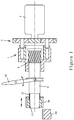
Figure 1 is a schematic view of a portion of a vehicle starter according to a preferred embodiment of the invention. -
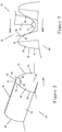
Figure 2 is an enlarged schematic view of a tooth of the pinion of the starter. -
Figure 3 is an enlarged schematic view showing a tooth of the pinion of the starter being engaged with the teeth of the ring gear. -
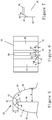
Figure 4 is an enlarged schematic view showing the stages for engaging the pinion of the starter with the ring gear. -
Figures 5 and 6 are schematic front and top views showing parameters of the chamfers of the tooth of the pinion. -
Figure 7 is a schematic view showing the inclination of the top chamfer of the tooth of the pinion. -
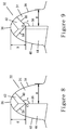
Figure 8 is a schematic front view for explaining the optimization of the top chamfer according to the principle of the invention. -
Figure 9 is a schematic front view for explaining the combined optimization of the top chamfer and the side chamfer according to the principle of the invention. - Now some preferred embodiments of the invention will be described with reference to the drawings.
-
Figure 1 shows a portion of a vehicle starter according to a preferred embodiment of the invention. The starter mainly comprises aDC motor 1, a transmission mechanism, a control device, etc. - The
motor 1 is mounted in a housing (not shown) of the starter. When the engine of the vehicle is to be started, the control device functions to supply themotor 1 with a DC electric current from a battery of the vehicle, so that themotor 1 runs to generate a rotational torque. The rotational torque is transmitted to aring gear 20 on a flywheel of the engine via the transmission mechanism to drive a crank shaft of the engine to rotate. - The transmission mechanism mainly comprises a
speed reducing mechanism 2 coupled with the output shaft of themotor 1, anoverrunning clutch 4 coupled with thespeed reducing mechanism 2, adrive shaft 8 having an back end (the end near the motor 1) coupled with theoverrunning clutch 4 via an axiallyslidable spline 6, and a pinion (the driving gear) 30 mounted to a front end (the end away from the motor 1) of thedrive shaft 8 for driving the ring gear (driven gear) 20. - The
speed reducing mechanism 2 may be any type of speed reducing mechanism, for example, the planetary gear type speed reducing mechanism shown inFigure 1 . Thespeed reducing mechanism 2 has an output end coupled with a driving part of theoverrunning clutch 4, and a driven part of theoverrunning clutch 4 transmits a rotational movement from thespeed reducing mechanism 2 to thedrive shaft 8 via thespline 6. - The
spline 6 is slidable in an axial direction to apply an axial displacement to thedrive shaft 8. Such an axial displacement is effected by alever 10 of the control device. Thelever 10 is able to pivot about a pivot shaft at its middle portion in opposite directions indicated by the curved arrows as shown inFigure 1 to drive thedrive shaft 8 to be axially displaced in opposite directions indicated by the straight arrows as shown inFigure 1 . - Further, the
pinion 30 is mounted to a front end segment of thedrive shaft 8 in a way of axially slidable with respect to thedrive shaft 8. Areturn spring 12 mounted around the front end segment of the drive shaft pushes forwards against thepinion 30. The drive shaft is provided with a stop element or structure, for example, aclamp ring 14 shown inFigure 1 , for retaining thepinion 30 in a front most position with respect to thedrive shaft 8 to prevent thepinion 30 from being further moved forwards. - When the
drive shaft 8 is in the axially back most position as shown inFigure 1 , thepinion 30 is disengaged from thering gear 20 on the flywheel of the engine. - When the starter is turned on, the control device controls the
lever 10 to pivot to drive thedrive shaft 8 to move forwards, and thepinion 30 is moved forwards with thedrive shaft 8. When thepinion 30 comes into contact with thering gear 20, the teeth of thepinion 30 generally cannot be engaged into the slots of thering gear 20 immediately. Rather, one or more teeth of thepinion 30 abut end-to-end against one or more teeth of thering gear 20. Now, thepinion 30 is stopped by thering gear 20 in the axial direction and cannot be moved forwards any further with thedrive shaft 8, so thereturn spring 12 is compressed. Then, the control device activates themotor 1, so that the output rotational movement of themotor 1 is transmitted to thepinion 30 via thespeed reducing mechanism 2, the overrunningclutch 4, thespline 6 and thedrive shaft 8 in sequence, so that thepinion 30 rotates with respect to thering gear 20. After a certain rotational angle has been rotated through, some teeth of thepinion 30 slide into the slots of thering gear 20 under the pushing force of thereturn spring 12, as a result of which, thepinion 30 and thering gear 20 are meshed with each other. In this way, thepinion 30 drives thering gear 20 to rotate, whereby the flywheel of the engine is driven to rotate, and thus the engine is started. Once the engine is started, the control device controls thelever 10 to move thedrive shaft 8 backwards, so that thepinion 30 is disengaged from thering gear 20. -
Figure 2 schematically shows atooth 32 of thepinion 30. Thetooth 32 is inserted, from itsfront end face 34, into a slot of the ring gear, and then drives a tooth of the ring gear in the direction indicated by the arrow shown inFigure 2 . Thetooth 32 comprises the front end face 34 which is perpendicular to the central axis of the pinion, atop land 36 extending backwards from the front end face, and a drivingflank 38 and anon-driving flank 40 formed on opposite sides of the top land respectively. - As can be understood from the discussion in the Background Art part of the present application, it is desired that the
pinion 30 can be engaged into the ring gear as quickly as possible. For this end, atop chamfer 42 and aside chamfer 44 are generally formed on the front end face 34 of eachtooth 32 of thepinion 30. - The
top chamfer 42 is formed between thetop land 36 and thefront end face 34, forming afirst intersection line 46 and asecond intersection line 48 with thetop land 36 and the front end face 34 respectively, and forming athird intersection line 50 and afourth intersection line 52 with the drivingflank 38 and thenon-driving flank 40 respectively. - The
side chamfer 44 is formed between thenon-driving flank 40 and thefront end face 34, forming afifth intersection line 54 and asixth intersection line 56 with thenon-driving flank 40 and the front end face 34 respectively. Further, aseventh intersection line 58 is formed between thetop chamfer 42 and theside chamfer 44. - The
second intersection line 48, thesixth intersection line 56 and theseventh intersection line 58 meet at an intersection point O, which is the radially inner most point of thetop chamfer 42. - It is appreciated that the above intersection lines may each be a straight line or a curved line.
- It should be noted that the
top chamfer 42 and theside chamfer 44 may each be in the form of a planar surface, as shown in the drawings. However, the invention also covers the embodiments in which thetop chamfer 42 and/or theside chamfer 44 is a curved surface. - As shown in
Figure 3 , eachtooth 22 of thering gear 20 comprises atop land 21, and a drivenflank 23 and anon-driven flank 25 formed on opposite sides of thetop land 21 respectively. When thepinion 30 drives thering gear 20, the drivingflank 38 of atooth 32 of thepinion 30 pushes against the drivenflank 23 of a correspondingtooth 22 of thering gear 20 to drive thering gear 20 to rotate. Thetooth 32 which is currently driving thetooth 22 of thering gear 20 is referred to as the main tooth which provides the maximum driving force. - The
tooth 22 is formed with aside chamfer 26, which is formed between thenon-driven flank 25 and the facing end face 27 (the end face facing towards the starter, which is facing away from the viewer who is looking atFigures 3 and4 ) of thetooth 22. Intersection lines are formed between theside chamfer 26 and corresponding faces of thetooth 22. It does not need to form top chamfers on the ring gear for achieving the engagement between the pinion and the ring gear. - It is appreciated that, although the intersection lines on the pinion and the ring gear are illustrated in the form of clear lines, at least one to all of the intersection lines may be machined to present rounded edges, so that the engaging of the pinion with the ring gear can be achieved more quickly and more smoothly. It is also appreciated that other edges or intersection lines between the pinion and the ring gear may also be machined to present rounded edges.
Figure 4 schematically shows the engaging procedure of thepinion 30 into thering gear 20 by stages (a) - (f) in sequence. In these stages, thepinion 30 rotates in the direction indicated by the arrow as illustrated, while thering gear 20 remains stationary. Two teeth of each of the pinion and the ring gear are depicted inFigure 4 for describing the engaging procedure. - Stage (a) represents an extreme initial engaging state. The
pinion 30 should be rotated through the maximum engaging-in angle from the initial engaging state stage (a) before it is allowed to be engaged with thering gear 20. Of course, according to the initial position of the pinion, the real initial engaging state of the pinion may be one of stages (b) - (f), in the condition of which, thepinion 30 can be engaged with thering gear 20 only after it is rotated through an engaging-in angle which is smaller than the maximum engaging-in angle, even a zero engaging-in angle. - In stage (a), the driving flank of the front tooth of the
pinion 30 is aligned with the driven flank of the front tooth of thering gear 20, while the back tooth of thepinion 30 is not reached at the back tooth of thering gear 20 yet. - Then, as the pinion rotates, it comes into stage (b). Now a first contacting area (the left shaded area) is formed between the front end face 34 of the front tooth of the
pinion 30 and the facing end face 27 of the front tooth of thering gear 20, and a second contacting area (the right shaded area) is formed between the front end face of the back tooth of thepinion 30 and the facing end face of the back tooth of thering gear 20. - Then, as the pinion rotates further, it comes into stage (c), wherein the first and the second contacting areas have both been increased with respect to the previous stage.
- Then, as the pinion rotates further, it comes into stage (d), wherein the first contacting area becomes to be reduced with respect to the previous stage, and the second contacting area continues increasing.
- Then, as the pinion rotates further, it comes into stage (e), wherein the first contacting area continues reducing, and the second contacting area becomes to be reduced with respect to the previous stage.
- Then, as the pinion rotates further, the first contacting area is reduced to zero first, and the second contacting area is reduced to zero later, so that it comes into stage (f). In this stage, both the first and second contacting areas disappear, the
side chamfer 44 of the front tooth of thepinion 30 slides onto theside chamfer 26 of the front tooth of thering gear 20 and is guided by it, and the side chamfer of the back tooth of thepinion 30 slides onto the side chamfer of the back tooth of thering gear 20 and is guided by it. From stage (f), the front and back teeth of thepinion 30 can slide respectively into the slots of thering gear 20 facing them. - It can be seen from the above description that the first contacting area between the front tooth of the pinion and the corresponding tooth of the ring gear disappears earlier than the second contacting area between the back tooth of the pinion and the corresponding tooth of the ring gear. Thus, when the front tooth comes into a state that it is allowed to slide into a slot, the back tooth is still be blocked from sliding into the next slot, which results in long engaging-in time of the pinion.
- The invention is aimed at shortening the engaging-in time of the pinion. For this end, a basic solution of the invention is to modify the top chamfer and/or side chamfer of the pinion, so that in the engaging-in procedure of the pinion, the time at which the back tooth is allowed to slide in (rotational angle position) and the time at which the front tooth is allowed to slide in (rotational angle position) are as close to each other as possible, even are coincident with each other.
- Some parameters related with the top chamfer and the side chamfer of the pinion will be defined before the embodiments of the invention are described in details.
- First, with reference to
Figure 5 which shows in a front view atooth 32 of the pinion in the axial direction of the pinion, the angle formed between thesecond intersection line 48 and the longitudinal central axis of the tooth (i.e., a line connecting the center of the pinion and the center of the top land, not shown) is represented by α, the vertical height measured from an intersection point O of thesecond intersection line 48, thesixth intersection line 56 and theseventh intersection line 58 to thetop land 36 is represented by H, and the lateral distance measured from thesixth intersection line 56 to the root of the drivingflank 38 is represented by W. - It should be noted that, in the illustrated embodiment, the
sixth intersection line 56 is parallel with the longitudinal central axis of the tooth, thus the angle α is marked between thesecond intersection line 48 and thesixth intersection line 56 for clear; it is appreciated that, however, thesixth intersection line 56 may not be parallel with the longitudinal central axis of the tooth in some embodiments. - Then, with reference to
Figure 6 which shows thetooth 32 of the pinion in a top view taken directly above it, the angle formed between theside chamfer 44 and thefront end face 34 is represented by β. The axial distance measured from the intersection point P of thefirst intersection line 46 and thethird intersection line 50 to thefront end face 34 is represented by e. - Then, with reference to
Figure 7 which is taken in a direction parallel with both thefront end face 34 and thetop chamfer 42, the angle formed between thefront end face 34 and thetop chamfer 42 is represented by γ. It can be seen that, with respect to thefront end face 34, thetop chamfer 42 is not only inclined in an axially backward direction, but also inclined towards the non-driving flank. The intersection point Q of thefirst intersection line 46 and theseventh intersection line 58 is located at an axial position which is backward from the axial position of the intersection point P of thefirst intersection line 46 and thethird intersection line 50. - According to an embodiment of the invention, optimization of the top chamfer is conducted, as shown in
Figure 8 , wherein parameters to be optimized include the above mentioned height H, angle α and angle γ, and the optimization target is that, in the engaging-in procedure, the contacting areas between (1) the front end faces of two teeth of the pinion which are neighbored with each other in the direction of rotation and are to be engaged into the ring gear and (2) the facing end faces of corresponding teeth of the ring gear can be reduced to zero at substantially the same as possible. - Specifically, after the pinion rotates from the extreme initial engaging state in stage (a) shown in
Figure 4 through a first angle, the front one of the two neighboring front and back teeth of the pinion that are to be engaged in comes into a ready-to-slide-in state. However, now the back tooth has not come into the ready-to-slide-in state. Then, after the pinion further rotates through an additional angle, the back tooth also comes into the ready-to-slide-in state. Thus, the maximum rotational angle through which the whole pinion is allowed to be engaged in is equals to the first angle plus the additional angle. - It should be noted that, the required rotational angle (the first angle) through which the front tooth reaches the ready-to-slide-in state mainly depends on the width of the side chamfer. By increasing the width of the side chamfer, the first angle can be reduced. However, taken into consideration of other aspects, the width of the side chamfer cannot be increased indefinitely. Thus, according to the invention, optimization of the top chamfer of the pinion is conducted first for reducing the value of the additional angle.
- Some main parameters related with the top chamfer and the side chamfer in an embodiment in which optimization is to be conducted to the top chamfer in the mating structure of the pinion and the ring gear are listed in the table below.
the pinion the ring gear Number of teeth 12 159 Normal module 3 3 Pressure angle 14.5° 15° Tooth width 23.5 mm 20 mm Addendum factor 1.000 1.066 Dedendum factor 1.197 1.134 Radius of the tooth fillet 0.6 mm 2.5 mm Addendum modification factor 0.780 -0.066 Helical angle 0° 0° - Main parameters before optimization:
H=2 mm, α=121°, γ=34°, W=3.1 mm, e=0.96 mm. - The maximum rotational angle required for engaging-in (i.e., the angle that the pinion should be rotated through from the extreme initial engaging state in stage (a) shown in
Figure 4 to stage (f) in which the pinion is allowed to be engaged into the ring gear) before optimization is 18.5°. - More specifically, when the pinion is rotated through the first angle of about 14° from the extreme initial engaging state in stage (a) shown in
Figure 4 , the front one of the two neighboring front and back teeth of the pinion that are to be engaged in comes into a ready-to-slide-in state. However, now the back tooth has not reached the ready-to-slide-in state yet. After the pinion is further rotated through the additional angle of 4°, the back tooth comes into the ready-to-slide-in state also. Thus, the maximum rotational angle through which the whole pinion is allowed to be engaged in is as large as 18.5°. By setting the optimization target as reducing the additional angle, the main parameters obtained after the optimization of the top chamfer are changed to:
H=4.5 mm, α=149°, γ=25°, W=3.1 mm, e=0.9 mm. - After the optimization of the top chamfer, the maximum rotational angle through which the whole pinion is allowed to be engaged in is about 14°.
- It can be seen that, by conducting optimization of the top chamfer, the required additional angle through which the back tooth comes into the ready-to-slide-in state is reduced to approximately zero, and thus the required rotational angles for the two tooth coming into the ready-to-slide-in state are nearly the same. In this way, the maximum rotational angle through which the whole pinion is allowed to be engaged in is reduced (reduced by 4.5° in the above embodiment, or by a reducing rate of about 19%).
- According to a further embodiment of the invention, optimization of the side chamfer is conducted, as shown in
Figure 9 , wherein optimization parameter is the above mentioned lateral distance W (essentially optimization of the width of the side chamfer), with the optimization target being that the contacting areas between (1) the
front end faces of the two neighboring front and back teeth of the pinion which are to be engaged in and (2) the facing end faces of the corresponding teeth of the ring gear is reduced to zero as quickly as possible. - An embodiment in which optimization of the side chamfer is further conducted on the basis of the embodiment where the optimization of the top chamfer as described above has been finished will be described now.
- Main parameters of the top chamfer and the side chamfer after the combined optimization include:
H=4.5 mm, α=149°, γ=25°, W=2.2 mm, e=1.2 mm. - By means of the combined optimization of the top chamfer and the side chamfer, the maximum rotational angle through which the whole pinion is allowed to be engaged in is about 12°.
- Thus, after the combined optimization of the top chamfer and the side chamfer, the maximum rotational angle through which the whole pinion is allowed to be engaged in is reduced significantly (reduced by 6.5° in the above embodiment, or by a reducing rate of about 28%).
- According to the invention, combined optimizations of the top chamfer and the side chamfer have been conducted based on the structure composed of the pinion and the ring gear which have varied parameters, so that general ranges of the values of the optimization parameters are set as listed below:
- Height H: 0.4 to 0.75 times, preferably 0.5 to 0.7 times, the height of the tooth.
- Angle α: 125 to 155°, preferably 135 to 150°.
- Angle γ: 15 to 32°, preferably 20 to 30°.
- Lateral distance W: 0.3 to 0.65 times, preferably 0.35 to 0.5 times, the thickness of the tooth.
- It is appreciated that, for different structures composed of the pinion and the ring gear, the ranges of the above parameters may be varied.
- Further, as to the angle β formed between the
side chamfer 44 and thefront end face 34, it has nearly no effect on the maximum rotational angle necessary for engaging-in, but has effects on the inserting procedure after the teeth of the pinion are allowed to be engaged into the slots of the ring gear as well as effects on the strength of the front end of the pinion. Taking all the factors into consideration in balance, the value of the angle β is generally set in the range of 20 to 60°, preferably 30 to 50°. - Those skilled in the art can understand that the above optimization can be carried out by various concrete computer programs for optimization.
- Further, in the above embodiments, the teeth of the pinion and the ring gear are all straight teeth; however, the invention is also applicable in the case where the teeth of the pinion and the ring gear are helical teeth.
- According to the invention, by conducting combined optimization to the top chamfer and the side chamfer of each tooth of the pinion, the maximum rotational angle required for engaging-in of the pinion can be reduced significantly. Thus, when the starter is actuated, the pinion can be engaged into the ring gear on the flywheel of the engine in a shortened time, so that the engine can be started more quickly and more smoothly. In addition, the tooth milling action of the pinion applied to the ring gear can be suppressed.
- The pinion in which combined optimization has conducted to the top chamfer and the side chamfer according to the invention is applicable in various vehicle starters, for example, starters for diesel vehicles.
- While certain embodiments have been described, these embodiments have been presented by way of example only. The attached claims are intended to cover all the modifications, substitutions and changes as would fall within the scope of the claims.
Claims (10)
- A driving gear (30) of a vehicle starter, comprising a plurality of teeth, each tooth (32) comprising a top chamfer (42) formed between a top land (36) and a front end face (34) of the tooth (32) and a side chamfer (44) formed between a non-driving flank (40) and the front end face (34) of the tooth (32); the driving gear being characterized in that the distance (H) from a radially inner most point of the top chamfer (42) to the top land (36) is in the range of 0.4 to 0.75 times the height of the tooth (32); the angle (α) formed between the intersection line between the top chamfer (42) and the front end face (34) and a longitudinal central axis of the tooth (32) is in the range of 125 to 155°; and the angle (γ) between the top chamfer (42) and the front end face (34) is in the range of 15 to 32°.
- The driving gear (30) of claim 1, wherein the distance (H) from the radially inner most point of the top chamfer (42) to the top land (36) is in the range of 0.5 to 0.7 times the height of the tooth (32).
- The driving gear (30) of claim 1 or 2, wherein the angle (α) formed between the intersection line between the top chamfer (42) and the front end face (34) and the longitudinal central axis of the tooth (32) is in the range of 135 to 150°.
- The driving gear (30) of claim 1 or 2, wherein the angle (γ) formed between the top chamfer (42) and the front end face (34) is in the range of 20 to 30°.
- The driving gear (30) of any one of claims 1 to 4, wherein the lateral distance (W) from the intersection line between the side chamfer (44) and the front end face (34) to the root of the driving flank (38) is in the range of 0.3 to 0.65 times the thickness of the tooth (32).
- The driving gear (30) of any one of claims 1 to 4, wherein the lateral distance (W) from the intersection line between the side chamfer (44) and the front end face (34) to the root of the driving flank (38) is in the range of 0.35 to 0.5 times the thickness of the tooth (32).
- The driving gear (30) of any one of claims 1 to 6, wherein at least one to all of the intersection lines between any two of the top land (36), the driving flank (38), a non-driving flank (40) which is opposite to the driving flank (38), the top chamfer (42) and the side chamfer (44) of a tooth (32) are in the form of rounded edges.
- The driving gear (30) of any one of claims 1 to 7, wherein the angle (β) formed between the side chamfer (44) and the front end face (34) is in the range of 20 to 60°.
- The driving gear (30) of any one of claims 1 to 8, wherein the angle (β) formed between the side chamfer (44) and the front end face (34) is in the range of 30 to 50°.
- A vehicle starter, comprising:a motor (1);a speed reducing mechanism (2) coupled with an output shaft of the motor;an overrunning clutch (4) coupled with the speed reducing mechanism (2);a drive shaft (8) coupled with the overrunning clutch (2) via a spline; anda driving gear (30) of any one of claims 1 to 9, carried by the drive shaft (8), for outputting a rotational movement.
Applications Claiming Priority (2)
| Application Number | Priority Date | Filing Date | Title |
|---|---|---|---|
| CN201210025312.9A CN103244640B (en) | 2012-02-06 | 2012-02-06 | Vehicle starter and driving gear thereof |
| PCT/CN2013/071463 WO2013117161A1 (en) | 2012-02-06 | 2013-02-06 | Vehicle starter and driving gear thereof |
Publications (3)
| Publication Number | Publication Date |
|---|---|
| EP2812610A1 EP2812610A1 (en) | 2014-12-17 |
| EP2812610A4 EP2812610A4 (en) | 2016-08-03 |
| EP2812610B1 true EP2812610B1 (en) | 2020-07-08 |
Family
ID=48924381
Family Applications (1)
| Application Number | Title | Priority Date | Filing Date |
|---|---|---|---|
| EP13746597.7A Not-in-force EP2812610B1 (en) | 2012-02-06 | 2013-02-06 | Vehicle starter and driving gear thereof |
Country Status (4)
| Country | Link |
|---|---|
| EP (1) | EP2812610B1 (en) |
| CN (1) | CN103244640B (en) |
| HU (1) | HUE050674T2 (en) |
| WO (1) | WO2013117161A1 (en) |
Families Citing this family (3)
| Publication number | Priority date | Publication date | Assignee | Title |
|---|---|---|---|---|
| DE102014217150A1 (en) * | 2014-08-28 | 2016-03-03 | Robert Bosch Gmbh | Starter pinion for a starter |
| FR3048734B1 (en) * | 2016-03-09 | 2019-07-05 | Valeo Equipements Electriques Moteur | MOTOR VEHICLE STARTER GEAR WITH IMPROVED ACOUSTIC PERFORMANCE |
| EP3428444A1 (en) | 2017-07-10 | 2019-01-16 | Mahle International GmbH | Starter motor for an internal combustion engine |
Family Cites Families (8)
| Publication number | Priority date | Publication date | Assignee | Title |
|---|---|---|---|---|
| JP2001248710A (en) * | 2000-03-02 | 2001-09-14 | Hitachi Ltd | Involute gear device and engine starting device using the same |
| JP2002250428A (en) | 2001-02-26 | 2002-09-06 | Hitachi Ltd | Involute gear unit, engine starting mechanism, and starter |
| JP2009236265A (en) * | 2008-03-28 | 2009-10-15 | Mitsuba Corp | Engine starter |
| KR20100063307A (en) * | 2008-12-03 | 2010-06-11 | 현대자동차주식회사 | Gear engaging performance determine lig apparatus and determine method thereof |
| DE102008054979A1 (en) | 2008-12-19 | 2010-06-24 | Robert Bosch Gmbh | Method and device for start-stop systems of internal combustion engines in motor vehicles |
| DE102010038443A1 (en) * | 2010-07-27 | 2012-02-02 | Robert Bosch Gmbh | Asymmetrical toothing |
| CN202017755U (en) * | 2011-04-27 | 2011-10-26 | 北京佩特来电器有限公司 | Driving gear and starting motor comprising same |
| CN202441836U (en) * | 2012-02-06 | 2012-09-19 | 博世汽车部件(长沙)有限公司 | Vehicle starter and driving gear thereof |
-
2012
- 2012-02-06 CN CN201210025312.9A patent/CN103244640B/en active Active
-
2013
- 2013-02-06 WO PCT/CN2013/071463 patent/WO2013117161A1/en not_active Ceased
- 2013-02-06 HU HUE13746597A patent/HUE050674T2/en unknown
- 2013-02-06 EP EP13746597.7A patent/EP2812610B1/en not_active Not-in-force
Non-Patent Citations (1)
| Title |
|---|
| None * |
Also Published As
| Publication number | Publication date |
|---|---|
| CN103244640B (en) | 2017-03-22 |
| HUE050674T2 (en) | 2020-12-28 |
| CN103244640A (en) | 2013-08-14 |
| EP2812610A1 (en) | 2014-12-17 |
| EP2812610A4 (en) | 2016-08-03 |
| WO2013117161A1 (en) | 2013-08-15 |
Similar Documents
| Publication | Publication Date | Title |
|---|---|---|
| US8708861B2 (en) | Electric power tool | |
| US10436169B2 (en) | Method and device for start-stop systems of internal combustion engines in motor vehicles | |
| WO2013117158A1 (en) | Vehicle starter and spline assembly thereof | |
| EP2812610B1 (en) | Vehicle starter and driving gear thereof | |
| JP6685768B2 (en) | Drive transmission | |
| US20130192419A1 (en) | Engine starting device | |
| US10415531B2 (en) | Engine starter with torque variator | |
| US9334845B2 (en) | Engine starting device | |
| JP2009168230A (en) | Pinion and starter using the same | |
| CN105680619A (en) | Motor assembly and vehicle starter | |
| JP6322229B2 (en) | Spur gear | |
| KR101501868B1 (en) | Engine starting device | |
| JP6012788B2 (en) | Engine starter | |
| JP5444503B2 (en) | Engine starter | |
| US20170234372A1 (en) | Synchronizer device and synchronization method | |
| EP1970560B1 (en) | Engine starter having improved helical spline structure for ensuring reliable engagement between output shaft and pinion gear | |
| CN202441836U (en) | Vehicle starter and driving gear thereof | |
| US9683534B2 (en) | Starter and engaging device thereof | |
| US2125526A (en) | Power transmission mechanism | |
| CN106715890B (en) | starting device | |
| CN209743413U (en) | Spline connection structure reaches starter including it | |
| US8987956B2 (en) | High speed clutch design with jaw tooth profile to reduce separating load | |
| CN202431421U (en) | Vehicle starter and spline device thereof | |
| CN211975706U (en) | Gear transmission assembly | |
| JP2016056723A (en) | Engine starter |
Legal Events
| Date | Code | Title | Description |
|---|---|---|---|
| PUAI | Public reference made under article 153(3) epc to a published international application that has entered the european phase |
Free format text: ORIGINAL CODE: 0009012 |
|
| 17P | Request for examination filed |
Effective date: 20140908 |
|
| AK | Designated contracting states |
Kind code of ref document: A1 Designated state(s): AL AT BE BG CH CY CZ DE DK EE ES FI FR GB GR HR HU IE IS IT LI LT LU LV MC MK MT NL NO PL PT RO RS SE SI SK SM TR |
|
| AX | Request for extension of the european patent |
Extension state: BA ME |
|
| DAX | Request for extension of the european patent (deleted) | ||
| RA4 | Supplementary search report drawn up and despatched (corrected) |
Effective date: 20160706 |
|
| RIC1 | Information provided on ipc code assigned before grant |
Ipc: F02N 15/00 20060101ALN20160630BHEP Ipc: H02K 7/10 20060101ALI20160630BHEP Ipc: F02N 15/06 20060101ALI20160630BHEP Ipc: F02N 11/00 20060101ALN20160630BHEP Ipc: F16H 55/17 20060101AFI20160630BHEP |
|
| RAP1 | Party data changed (applicant data changed or rights of an application transferred) |
Owner name: SEG AUTOMOTIVE GERMANY GMBH Owner name: BOSCH AUTOMOTIVE PRODUCTS (CHANGSHA) CO., LTD |
|
| RAP1 | Party data changed (applicant data changed or rights of an application transferred) |
Owner name: SEG AUTOMOTIVE GERMANY GMBH |
|
| REG | Reference to a national code |
Ref country code: DE Ref legal event code: R079 Ref document number: 602013070513 Country of ref document: DE Free format text: PREVIOUS MAIN CLASS: F16H0055170000 Ipc: H02K0007100000 |
|
| RIC1 | Information provided on ipc code assigned before grant |
Ipc: F02N 15/00 20060101ALN20191210BHEP Ipc: F16H 55/08 20060101ALI20191210BHEP Ipc: H02K 7/10 20060101AFI20191210BHEP Ipc: F02N 11/00 20060101ALN20191210BHEP Ipc: F02N 15/06 20060101ALI20191210BHEP |
|
| GRAP | Despatch of communication of intention to grant a patent |
Free format text: ORIGINAL CODE: EPIDOSNIGR1 |
|
| STAA | Information on the status of an ep patent application or granted ep patent |
Free format text: STATUS: GRANT OF PATENT IS INTENDED |
|
| INTG | Intention to grant announced |
Effective date: 20200121 |
|
| GRAS | Grant fee paid |
Free format text: ORIGINAL CODE: EPIDOSNIGR3 |
|
| GRAA | (expected) grant |
Free format text: ORIGINAL CODE: 0009210 |
|
| STAA | Information on the status of an ep patent application or granted ep patent |
Free format text: STATUS: THE PATENT HAS BEEN GRANTED |
|
| AK | Designated contracting states |
Kind code of ref document: B1 Designated state(s): AL AT BE BG CH CY CZ DE DK EE ES FI FR GB GR HR HU IE IS IT LI LT LU LV MC MK MT NL NO PL PT RO RS SE SI SK SM TR |
|
| REG | Reference to a national code |
Ref country code: GB Ref legal event code: FG4D |
|
| REG | Reference to a national code |
Ref country code: AT Ref legal event code: REF Ref document number: 1289527 Country of ref document: AT Kind code of ref document: T Effective date: 20200715 Ref country code: CH Ref legal event code: EP |
|
| REG | Reference to a national code |
Ref country code: DE Ref legal event code: R096 Ref document number: 602013070513 Country of ref document: DE |
|
| REG | Reference to a national code |
Ref country code: IE Ref legal event code: FG4D |
|
| REG | Reference to a national code |
Ref country code: LT Ref legal event code: MG4D |
|
| REG | Reference to a national code |
Ref country code: AT Ref legal event code: MK05 Ref document number: 1289527 Country of ref document: AT Kind code of ref document: T Effective date: 20200708 |
|
| REG | Reference to a national code |
Ref country code: NL Ref legal event code: MP Effective date: 20200708 |
|
| REG | Reference to a national code |
Ref country code: HU Ref legal event code: AG4A Ref document number: E050674 Country of ref document: HU |
|
| PG25 | Lapsed in a contracting state [announced via postgrant information from national office to epo] |
Ref country code: PT Free format text: LAPSE BECAUSE OF FAILURE TO SUBMIT A TRANSLATION OF THE DESCRIPTION OR TO PAY THE FEE WITHIN THE PRESCRIBED TIME-LIMIT Effective date: 20201109 Ref country code: AT Free format text: LAPSE BECAUSE OF FAILURE TO SUBMIT A TRANSLATION OF THE DESCRIPTION OR TO PAY THE FEE WITHIN THE PRESCRIBED TIME-LIMIT Effective date: 20200708 Ref country code: BG Free format text: LAPSE BECAUSE OF FAILURE TO SUBMIT A TRANSLATION OF THE DESCRIPTION OR TO PAY THE FEE WITHIN THE PRESCRIBED TIME-LIMIT Effective date: 20201008 Ref country code: HR Free format text: LAPSE BECAUSE OF FAILURE TO SUBMIT A TRANSLATION OF THE DESCRIPTION OR TO PAY THE FEE WITHIN THE PRESCRIBED TIME-LIMIT Effective date: 20200708 Ref country code: LT Free format text: LAPSE BECAUSE OF FAILURE TO SUBMIT A TRANSLATION OF THE DESCRIPTION OR TO PAY THE FEE WITHIN THE PRESCRIBED TIME-LIMIT Effective date: 20200708 Ref country code: FI Free format text: LAPSE BECAUSE OF FAILURE TO SUBMIT A TRANSLATION OF THE DESCRIPTION OR TO PAY THE FEE WITHIN THE PRESCRIBED TIME-LIMIT Effective date: 20200708 Ref country code: GR Free format text: LAPSE BECAUSE OF FAILURE TO SUBMIT A TRANSLATION OF THE DESCRIPTION OR TO PAY THE FEE WITHIN THE PRESCRIBED TIME-LIMIT Effective date: 20201009 Ref country code: SE Free format text: LAPSE BECAUSE OF FAILURE TO SUBMIT A TRANSLATION OF THE DESCRIPTION OR TO PAY THE FEE WITHIN THE PRESCRIBED TIME-LIMIT Effective date: 20200708 Ref country code: NO Free format text: LAPSE BECAUSE OF FAILURE TO SUBMIT A TRANSLATION OF THE DESCRIPTION OR TO PAY THE FEE WITHIN THE PRESCRIBED TIME-LIMIT Effective date: 20201008 Ref country code: ES Free format text: LAPSE BECAUSE OF FAILURE TO SUBMIT A TRANSLATION OF THE DESCRIPTION OR TO PAY THE FEE WITHIN THE PRESCRIBED TIME-LIMIT Effective date: 20200708 |
|
| PG25 | Lapsed in a contracting state [announced via postgrant information from national office to epo] |
Ref country code: IS Free format text: LAPSE BECAUSE OF FAILURE TO SUBMIT A TRANSLATION OF THE DESCRIPTION OR TO PAY THE FEE WITHIN THE PRESCRIBED TIME-LIMIT Effective date: 20201108 Ref country code: LV Free format text: LAPSE BECAUSE OF FAILURE TO SUBMIT A TRANSLATION OF THE DESCRIPTION OR TO PAY THE FEE WITHIN THE PRESCRIBED TIME-LIMIT Effective date: 20200708 Ref country code: RS Free format text: LAPSE BECAUSE OF FAILURE TO SUBMIT A TRANSLATION OF THE DESCRIPTION OR TO PAY THE FEE WITHIN THE PRESCRIBED TIME-LIMIT Effective date: 20200708 Ref country code: PL Free format text: LAPSE BECAUSE OF FAILURE TO SUBMIT A TRANSLATION OF THE DESCRIPTION OR TO PAY THE FEE WITHIN THE PRESCRIBED TIME-LIMIT Effective date: 20200708 |
|
| PG25 | Lapsed in a contracting state [announced via postgrant information from national office to epo] |
Ref country code: NL Free format text: LAPSE BECAUSE OF FAILURE TO SUBMIT A TRANSLATION OF THE DESCRIPTION OR TO PAY THE FEE WITHIN THE PRESCRIBED TIME-LIMIT Effective date: 20200708 |
|
| REG | Reference to a national code |
Ref country code: DE Ref legal event code: R097 Ref document number: 602013070513 Country of ref document: DE |
|
| PG25 | Lapsed in a contracting state [announced via postgrant information from national office to epo] |
Ref country code: SM Free format text: LAPSE BECAUSE OF FAILURE TO SUBMIT A TRANSLATION OF THE DESCRIPTION OR TO PAY THE FEE WITHIN THE PRESCRIBED TIME-LIMIT Effective date: 20200708 Ref country code: RO Free format text: LAPSE BECAUSE OF FAILURE TO SUBMIT A TRANSLATION OF THE DESCRIPTION OR TO PAY THE FEE WITHIN THE PRESCRIBED TIME-LIMIT Effective date: 20200708 Ref country code: IT Free format text: LAPSE BECAUSE OF FAILURE TO SUBMIT A TRANSLATION OF THE DESCRIPTION OR TO PAY THE FEE WITHIN THE PRESCRIBED TIME-LIMIT Effective date: 20200708 Ref country code: EE Free format text: LAPSE BECAUSE OF FAILURE TO SUBMIT A TRANSLATION OF THE DESCRIPTION OR TO PAY THE FEE WITHIN THE PRESCRIBED TIME-LIMIT Effective date: 20200708 Ref country code: DK Free format text: LAPSE BECAUSE OF FAILURE TO SUBMIT A TRANSLATION OF THE DESCRIPTION OR TO PAY THE FEE WITHIN THE PRESCRIBED TIME-LIMIT Effective date: 20200708 Ref country code: CZ Free format text: LAPSE BECAUSE OF FAILURE TO SUBMIT A TRANSLATION OF THE DESCRIPTION OR TO PAY THE FEE WITHIN THE PRESCRIBED TIME-LIMIT Effective date: 20200708 |
|
| PLBE | No opposition filed within time limit |
Free format text: ORIGINAL CODE: 0009261 |
|
| STAA | Information on the status of an ep patent application or granted ep patent |
Free format text: STATUS: NO OPPOSITION FILED WITHIN TIME LIMIT |
|
| PG25 | Lapsed in a contracting state [announced via postgrant information from national office to epo] |
Ref country code: AL Free format text: LAPSE BECAUSE OF FAILURE TO SUBMIT A TRANSLATION OF THE DESCRIPTION OR TO PAY THE FEE WITHIN THE PRESCRIBED TIME-LIMIT Effective date: 20200708 |
|
| 26N | No opposition filed |
Effective date: 20210409 |
|
| PG25 | Lapsed in a contracting state [announced via postgrant information from national office to epo] |
Ref country code: SK Free format text: LAPSE BECAUSE OF FAILURE TO SUBMIT A TRANSLATION OF THE DESCRIPTION OR TO PAY THE FEE WITHIN THE PRESCRIBED TIME-LIMIT Effective date: 20200708 |
|
| PG25 | Lapsed in a contracting state [announced via postgrant information from national office to epo] |
Ref country code: SI Free format text: LAPSE BECAUSE OF FAILURE TO SUBMIT A TRANSLATION OF THE DESCRIPTION OR TO PAY THE FEE WITHIN THE PRESCRIBED TIME-LIMIT Effective date: 20200708 |
|
| PG25 | Lapsed in a contracting state [announced via postgrant information from national office to epo] |
Ref country code: MC Free format text: LAPSE BECAUSE OF FAILURE TO SUBMIT A TRANSLATION OF THE DESCRIPTION OR TO PAY THE FEE WITHIN THE PRESCRIBED TIME-LIMIT Effective date: 20200708 |
|
| GBPC | Gb: european patent ceased through non-payment of renewal fee |
Effective date: 20210206 |
|
| REG | Reference to a national code |
Ref country code: BE Ref legal event code: MM Effective date: 20210228 |
|
| PG25 | Lapsed in a contracting state [announced via postgrant information from national office to epo] |
Ref country code: LI Free format text: LAPSE BECAUSE OF NON-PAYMENT OF DUE FEES Effective date: 20210228 Ref country code: LU Free format text: LAPSE BECAUSE OF NON-PAYMENT OF DUE FEES Effective date: 20210206 Ref country code: CH Free format text: LAPSE BECAUSE OF NON-PAYMENT OF DUE FEES Effective date: 20210228 |
|
| REG | Reference to a national code |
Ref country code: DE Ref legal event code: R082 Ref document number: 602013070513 Country of ref document: DE Representative=s name: DEHNSGERMANY PARTNERSCHAFT VON PATENTANWAELTEN, DE Ref country code: DE Ref legal event code: R082 Ref document number: 602013070513 Country of ref document: DE Representative=s name: DEHNS GERMANY PARTNERSCHAFT MBB, DE |
|
| PG25 | Lapsed in a contracting state [announced via postgrant information from national office to epo] |
Ref country code: GB Free format text: LAPSE BECAUSE OF NON-PAYMENT OF DUE FEES Effective date: 20210206 Ref country code: IE Free format text: LAPSE BECAUSE OF NON-PAYMENT OF DUE FEES Effective date: 20210206 |
|
| PGFP | Annual fee paid to national office [announced via postgrant information from national office to epo] |
Ref country code: FR Payment date: 20220215 Year of fee payment: 10 |
|
| PG25 | Lapsed in a contracting state [announced via postgrant information from national office to epo] |
Ref country code: BE Free format text: LAPSE BECAUSE OF NON-PAYMENT OF DUE FEES Effective date: 20210228 |
|
| PGFP | Annual fee paid to national office [announced via postgrant information from national office to epo] |
Ref country code: HU Payment date: 20230126 Year of fee payment: 11 Ref country code: DE Payment date: 20220623 Year of fee payment: 11 |
|
| PG25 | Lapsed in a contracting state [announced via postgrant information from national office to epo] |
Ref country code: CY Free format text: LAPSE BECAUSE OF FAILURE TO SUBMIT A TRANSLATION OF THE DESCRIPTION OR TO PAY THE FEE WITHIN THE PRESCRIBED TIME-LIMIT Effective date: 20200708 |
|
| PG25 | Lapsed in a contracting state [announced via postgrant information from national office to epo] |
Ref country code: FR Free format text: LAPSE BECAUSE OF NON-PAYMENT OF DUE FEES Effective date: 20230228 |
|
| PG25 | Lapsed in a contracting state [announced via postgrant information from national office to epo] |
Ref country code: MK Free format text: LAPSE BECAUSE OF FAILURE TO SUBMIT A TRANSLATION OF THE DESCRIPTION OR TO PAY THE FEE WITHIN THE PRESCRIBED TIME-LIMIT Effective date: 20200708 |
|
| REG | Reference to a national code |
Ref country code: DE Ref legal event code: R119 Ref document number: 602013070513 Country of ref document: DE |
|
| PG25 | Lapsed in a contracting state [announced via postgrant information from national office to epo] |
Ref country code: MT Free format text: LAPSE BECAUSE OF FAILURE TO SUBMIT A TRANSLATION OF THE DESCRIPTION OR TO PAY THE FEE WITHIN THE PRESCRIBED TIME-LIMIT Effective date: 20200708 |
|
| PG25 | Lapsed in a contracting state [announced via postgrant information from national office to epo] |
Ref country code: HU Free format text: LAPSE BECAUSE OF NON-PAYMENT OF DUE FEES Effective date: 20240207 |
|
| PG25 | Lapsed in a contracting state [announced via postgrant information from national office to epo] |
Ref country code: HU Free format text: LAPSE BECAUSE OF NON-PAYMENT OF DUE FEES Effective date: 20240207 |
|
| PG25 | Lapsed in a contracting state [announced via postgrant information from national office to epo] |
Ref country code: DE Free format text: LAPSE BECAUSE OF NON-PAYMENT OF DUE FEES Effective date: 20240903 |
|
| PG25 | Lapsed in a contracting state [announced via postgrant information from national office to epo] |
Ref country code: DE Free format text: LAPSE BECAUSE OF NON-PAYMENT OF DUE FEES Effective date: 20240903 |
|
| PG25 | Lapsed in a contracting state [announced via postgrant information from national office to epo] |
Ref country code: TR Free format text: LAPSE BECAUSE OF FAILURE TO SUBMIT A TRANSLATION OF THE DESCRIPTION OR TO PAY THE FEE WITHIN THE PRESCRIBED TIME-LIMIT Effective date: 20200708 |